Embed Size (px)
Citation preview

Networks ∙ Services ∙ People www.geant.org
Guy Roberts
DFN-Forum Kommunikationstechnologien
State of the art and application in R&E networksOptical and DWDM technology
Lübeck, 8 June 2015
Transport Network Architect, GÉANT

Networks ∙ Services ∙ People www.geant.orgObjectives
• Today’s optical technology• The pre-coherent era
• Super-channels and photonic integration
• GÉANT network update in 2012• Alien Wave field trial update
• The future – the next generation of optical technology
Contents

Networks ∙ Services ∙ People www.geant.org
Optical Technology

Networks ∙ Services ∙ People www.geant.org
Wavelength Division MultiplexingScaling Fiber Capacity
DWDM Multiplexing -
Combining wavelengths
DWDM De-multiplexing -
Separating wavelengths
PreAmplifier

Networks ∙ Services ∙ People www.geant.org 5
Dense wavelength division multiplexingC band and ITU grid – before coherent technology
• Dense wavelength division multiplexing (DWDM)
• First used the 1525–1565 nm band (C band) to make use of erbium doped fibre amplifiers (EDFAs)
• Each wave carries a 10Gbps NRZ modulated signal
• Approx. 80 waves per fibre on C band 50GHz ITU-T grid
• Early systems used only fixed multiplexers• Reconfigurable Add Drop Multiplexers (ROADMs) allow
wavelengths to be switched and add/dropped under network management control

Networks ∙ Services ∙ People www.geant.org
Fiber impairmentsCompensating for fibre effects
AttenuationThe power of the signal is absorbed
as it passes along the fiber
DispersionThe signal pulse is “smeared out”
as it passes along the fiber
Chromatic Dispersion
Modal Dispersion
Polarization Mode Dispersion
Advances in optical transmission are driven by new techniques to remove
impairments
Non-LinearEffects

Networks ∙ Services ∙ People www.geant.org
A History of DWDM Capacity x Distance InnovationsEvolution up to 2006
Laser technology evolves to fiber/EDFA
“sweet spot”
EDFA innovation enables WDM –multiple waves
in a fiber
Chromatic Dispersion Management enables 2.5G to 10G evolution Forward Error
Correction directly increases Cap*Dist
Addition of L-Band could double fiber capacity*
Raman amplification gives excellent distance boost
Emmanuel B. Desurvire. “Capacity Demand and Technology Challenges for Lightwave Systems in the Next Two Decades”JOURNAL OF LIGHTWAVE TECHNOLOGY, VOL. 24, NO. 12, DECEMBER 2006
1

Networks ∙ Services ∙ People www.geant.org
• From intensity modulation to phase modulation• Polarization muxing
• Roughly 2x increase in Capacity * Reach• Increasing modulation order (BPSK, 3QAM, QPSK)
• Increasing the “bits per symbol”
• Coherent detection• Increased detector sensitivity• Linear detector, enables electronic CD and PMD compensation• >10x increase in Capacity * Reach
• Soft Decision Forward Error Correction (SD-FEC)• Roughly 2x increase in Capacity * Reach vs HD-FEC
The First Coherent EraInnovations are in production today
More bits/symbol allows the bit rate to be increased without increasing the symbol rate
2

Networks ∙ Services ∙ People www.geant.org
• Widespread adoption of photonic integrated circuits (PICs)*1• Introduction of transmitter-based signal processing• The move to higher order modulation (eg. 8QAM, 16QAM)• The move away from fixed DWDM grids to flexible grids• The ubiquitous use of super-channels
• An acceptance that we may be approaching capacity*reach product limits for optical transmission over existing fiber types
3
The Second Coherent EraWhat does the future hold?
*1 Infinera is the market leader in PIC technology today

Networks ∙ Services ∙ People www.geant.org
The Pre-Coherent Era
Networks ∙ Services ∙ People www.geant.org
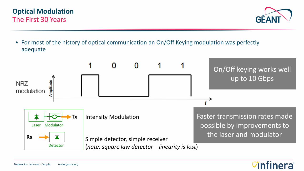
Optical ModulationThe First 30 Years
Laser Modulator
Detector
Tx
Rx
Intensity Modulation
Simple detector, simple receiver(note: square law detector – linearity is lost)
• For most of the history of optical communication an On/Off Keying modulation was perfectly adequate
On/Off keying works well up to 10 Gbps
Faster transmission rates made possible by improvements to
the laser and modulator

Networks ∙ Services ∙ People www.geant.org
What can we do about it?In the pre-coherent era
Attenuation
Modal dispersion
Chromatic Dispersion
PMD
Non-linear effects
Amplify the signal
Single mode fiber
Narrow line width lasers and dispersion Compensating Fiber
Too small to worry about up to 10Gb/s
Limit the power of the signal at any point in the fiber
Huge compute power of DSP can be harnessed to remove fibre impairments, but it requires a linear receiver….
Laser Modulator
Detector
Tx
Rx
Coherent detection

Networks ∙ Services ∙ People www.geant.org
The First Coherent EraApprox. 2010 – 2015
*These dates are open to interpretation, but I am using commercially available product as a benchmark

Networks ∙ Services ∙ People www.geant.org
…waves have a speed, wavelength and frequency
What does “coherent” mean?
Wavelength
Tx• More bits per symbol (eg. QPSK)• More tolerant to fiber impairments
Rx• Mix received signal with a local oscillator• Linear detector (allows use of DSP)
Use phase changes to encode data
Adapting radio modulation techniques

Networks ∙ Services ∙ People www.geant.org
Pol-Mux QPSK ModulationQPSK - 2 bits per symbol
Im{Ex}
Re{Ex}This structure called a “Super Mach Zehnder”
Laser
QuadraturePhaseShiftKeying
Q
I
90
S1
S2 Signalinputs
Shows one of the two polarizations

Networks ∙ Services ∙ People www.geant.org
QPSK Encoding + polarizationPM-QPSK, 4 bits per symbol
Q
I
X-Pol
Y-Pol
Q
I
X Polarization
Y Polarization
PM-QPSK carries 4 bits per “symbol”(A symbol is now the X and Y polarizations)

Networks ∙ Services ∙ People www.geant.org
Coherent WDM Detection
LO
The incoming signal that uses a phase-basedmodulation technique is sent into the mixer
This means there’s a “reference laser” in the receiver
Coherent Detector
PD Photodetector
ADC Analog to Digital Converter
DSP Digital Signal Processor
LOLocal Oscillator
It’s mixed with a reference signal from the local oscillator that is tuned to the
wavelength we would like to detect
ADC DSPPDMixer
Green SignalDetectedRed SignalDetected

Networks ∙ Services ∙ People www.geant.org
• Very low noise amplifier• Phase-based technique
• More robust in the face of fiber impairments• Allows us to use more complex phase constellations to cram more bits into a modulation symbol
• Polarization can be used as a modulation variable• Highly compatible with a parallel processing approach• Linear detector
• Enables us to use sophisticated signal processing for linear impairments
Key Advantages of Coherent Detection

Networks ∙ Services ∙ People www.geant.org
Coherent Detector In More DetailOne wavelength
Incoming carrier(2 polarizations, each with 4 phase states)
ADC A/D ConverterAMZ Adjustable Mach ZehnderDSP Digital Signal ProcessorLO Local OscillatorPD Photo DetectorPBS Polarization Beam Splitter LO
PD
PD
PD
PD
ADC
ADC
ADC
ADC
DSP
AMZ
AMZ
AMZ
AMZ
Optical Circuit Electronic Circuit
PBS
PBS

Networks ∙ Services ∙ People www.geant.org
LO
PD
PD
PD
PD
ADC
ADC
ADC
ADC
DSP
AMZ
AMZ
AMZ
AMZ
Optical Circuit Electronic Circuit
PBS
PBS
1
Step 1: Separate the X and Y polarizations
Incoming carrier(2 polarizations, each with 4 phase states)
ADC A/D ConverterAMZ Adjustable Mach ZehnderDSP Digital Signal ProcessorLO Local OscillatorPD Photo DetectorPBS Polarization Beam Splitter
Coherent Detector In More DetailOne wavelength

Networks ∙ Services ∙ People www.geant.org
LO
PD
PD
PD
PD
ADC
ADC
ADC
ADC
DSP
AMZ
AMZ
AMZ
AMZ
Optical Circuit Electronic Circuit
PBS
PBS
2
Step 2: Mix the two optical sources – signal and local oscillator
Incoming carrier(2 polarizations, each with 4 phase states)
ADC A/D ConverterAMZ Adjustable Mach ZehnderDSP Digital Signal ProcessorLO Local OscillatorPD Photo DetectorPBS Polarization Beam Splitter
Coherent Detector In More DetailOne wavelength

Networks ∙ Services ∙ People www.geant.org
LO
PD
PD
PD
PD
ADC
ADC
ADC
ADC
DSP
AMZ
AMZ
AMZ
AMZ
Optical Circuit Electronic Circuit
PBS
PBS
3
Step 3: Extract interference patterns in the AMZ array
Incoming carrier(2 polarizations, each with 4 phase states)
ADC A/D ConverterAMZ Adjustable Mach ZehnderDSP Digital Signal ProcessorLO Local OscillatorPD Photo DetectorPBS Polarization Beam Splitter
Coherent Detector In More DetailOne wavelength

Networks ∙ Services ∙ People www.geant.org
LO
PD
PD
PD
PD
ADC
ADC
ADC
ADC
DSP
AMZ
AMZ
AMZ
AMZ
Optical Circuit Electronic Circuit
PBS
PBS
4
Step 4: Convert optical signals to analog electronic signals
Coherent Detector In More Detail: One wavelength
Incoming carrier(2 polarizations, each with 4 phase states)
ADC A/D ConverterAMZ Adjustable Mach ZehnderDSP Digital Signal ProcessorLO Local OscillatorPD Photo DetectorPBS Polarization Beam Splitter

Networks ∙ Services ∙ People www.geant.org
LO
PD
PD
PD
PD
ADC
ADC
ADC
ADC
DSP
AMZ
AMZ
AMZ
AMZ
Optical Circuit Electronic Circuit
PBS
PBS
5
Step 5: ADC converts analog to digital and DSP will process
Incoming carrier(2 polarizations, each with 4 phase states)
ADC A/D ConverterAMZ Adjustable Mach ZehnderDSP Digital Signal ProcessorLO Local OscillatorPD Photo DetectorPBS Polarization Beam Splitter
Coherent Detector In More DetailOne wavelength

Networks ∙ Services ∙ People www.geant.org
Digital Signal ProcessingAt the core of coherent technology
CD C
omp.
CD C
omp.
Clock Recovery
PMD
Com
pens
atio
n
SD-F
EC
Cloc
k Re
cove
ryCl
ock
Reco
very
Deci
sion
and
Soft
Met
ricDe
cisio
n an
d So
ft M
etric
ADC1Ix
ADC2Qx
ADC3Iy
ADC4Qy
X-Pol Signal
Y-Pol Signal
I
Q
I
Q
21 3 4
1. CD compensation2. PMD compensation3. Intradyne clock recovery4. Soft Decision FEC

Networks ∙ Services ∙ People www.geant.org
Digital Signal ProcessingCompensating for chromatic dispersion
Tx Rx
1 or 0?If an optical pulse had an
ideal infinitely narrow
spectrum
But in practice real lasers have a
finite linewidth
This decision is much harder!
One pulse may actually merge
into the preceding and
following pulses
Reversal of this “smearing” of the signal is done with equalization using digital filters in the time and/or
frequency domain

Networks ∙ Services ∙ People www.geant.org
• Rapid changes in polarization need to be tracked• 2 polarizations are split into 4 linear equalizers• Peak PMD tolerance to 500ps• Tolerant to PMD transients of 10,000 rad/s
Digital Signal Processing, PMD CompensationInfinera PIC-Based, FlexCoherent Super-Channel Solution
Linear transversal equalizer. Taps are summed and weighted using algorithms:- adaptive least mean square (LMS) - constant modulus algorithms (CMA) equalization.
Rahn, J.; Sun, H.; Wu, K.T.; Basch, B.E. IEEE Journal of Lightwave Technology, 2012, Issue 99: Real-Time PMD Tolerance Measurements of a PIC Based 500Gb/s Coherent Optical Modem

Networks ∙ Services ∙ People www.geant.org
Hard and Soft Decision FEC Evolution
log (BER)(Lower is better)
Optical Signal to Noise Ratio (OSNR)
Impact of better FEC is to drive down OSNR for a given BER
No FEC
1
Without FEC, a high OSNR is needed to ensure a low Bit Error Rate (BER)1
HD-FEC
2
HD-FEC e.g Reed Solomon code, delivers >9dB of NCG 2
1st GenSD-FEC
3
1st Gen SD-FEC e.g convolution codes such as Viterbi, delivers >11dB of NCG
3
2nd GenSD-FEC
4
2nd Gen SD-FEC targeting 12dB of NCG4
DWDM vendor’s proprietary FEC solutions differentiate their
products from other vendors
Further FEC gains are getting harder and harder to achieve… “saturation” at about 12dB NCG

Networks ∙ Services ∙ People www.geant.org
Super-Channels andPhotonic Integration

Networks ∙ Services ∙ People www.geant.org
Can single wavelengths scale to higher data rates?Serial Electronics Performance Limitations
Transistors(000)
Clock Speed(MHz)
Performance
10M
100K
1K
10
1970 2010
Moore’s Law is still valid (# transistors on chip still scaling), but serial
processing rates have flat-lined
QPSK Data Rate per wavelength
Serial processing rate
100Gb/s 32GBaud
200Gb/s 64GBaud
400Gb/s 128GBaud
1.2Tb/s 384GBaud
For single wavelength transponders
Higher order modulation can help – but only with significant
reductions in reach

Networks ∙ Services ∙ People www.geant.org
Scaling the DWDM Layer to >100G
A Super-channel implements multiple carriers in a single line cardSingle operational cycle, Single unit of capacity
600 Optical Functions Integrated250 Fiber Connectors Eliminated
Power/Space ReducedReliability Enhanced
PIC makes it practical
500Gbps Line Card (1.2Tbps+ Future)
Super-Channel

Networks ∙ Services ∙ People www.geant.org
500Gb/s in a single line card
AOFX-1000-T8-1-C8
FC 1-4/1-6/1-8
Large Scale PICs Optimal for Super-Channels
500G RX PIC
500G TX PIC
10 channels of Tx
10 channels of Rx

Networks ∙ Services ∙ People www.geant.org
• Coherent has made it possible to break the “10Gb/s Barrier”
• The state of the market today (PM-QPSK) is:
A Review of First Generation Coherent Transmission
100Gb/s per wavelength
4,500kmreach
9.5Tb/sper fiber
Coherent super-channels add operational scale to these capabilities

Networks ∙ Services ∙ People www.geant.org
GÉANT network upgrade

Networks ∙ Services ∙ People www.geant.orgObjectives
• DTN-X solution from Infinera
Why Infinera?
• Photonic integration• Large pools of “virtualised” bandwidth
500G super channels
• Ease of use
• Excellent service wrap
For the optical layer GÉANT selected…

Networks ∙ Services ∙ People www.geant.orgObjectives
Convergence
ZONE
Backbone Network ArchitectureA major upgrade & rationalisation
Fibre Leased Circuits
GRBE TR ILEE LV LTSK
HR SI
UK
NL
DE
FR
ES DK
CZ
AT
IT
HU
CH
RO BG
PL
IE
MT CY
“Fully featured POPs” Off fibre netPOPs
IP/MPLS only POPs NREN POPs
(RouterlessPOPs)
Circuitsover GÉANT Leased
circuits
MK RS
ME
DWDM
TDM (SDH)
IP/MPLS
Packet Transport (IP/MPLS)PT LU
RU
Off fibre POPs
FRITDE
Hamburg AAP Marseille AAP
Milan (GARR) AAP
Converged Packet Transport Platform Leasedcircuits

Networks ∙ Services ∙ People www.geant.orgObjectives
• In GN3 the GÉANT dark fibre footprint has been re-procured.
• On most routes DANTE was able to negotiate a temporary second fibre pair to support migration.
• The fibre footprint update provide the opportunity to remove some shared-risk points in the network.
• A new flexibility point has been added to the network in Marseilles
• An AAP has been added in Hamburg and Milan.
• Significant improvements have been made to diversity around Geneva.
The shared risks have now been removed from both the east and west routes out of Geneva.
Re-procurement in GÉANT3Dark Fibre and Additional Access Points (AAPs)
New GÉANT day-1DF footprint
Out fromGeneva
New diversity east of Geneva
Improved diversitytowards NL & DKImproved Frankfurt diversity
Networks ∙ Services ∙ People www.geant.org
Alien Waves

Networks ∙ Services ∙ People www.geant.org
Field Trial
• GÉANT has made use of SURFnet’s dark fibre to carry GÉANT DWDM trunks.• Field trial is now complete and showed excellent results
• Production grade service is now planned
39
Alien WavesDo aliens and lasers mix?
Alien Waves
• ‘Alien’ refers to data transmission laser light from 3rd party equipment• An alien wave system multiplexes alien light together with local signals
using Dense Wavelength Division Multiplex (DWDM) technology.

Networks ∙ Services ∙ People www.geant.org 40
Alien WavesEconomic theory
• Economics textbook theory shows that a system with fixed and variable costs has a break-even point.
• At a fixed price, low volumes result in a loss.

Networks ∙ Services ∙ People www.geant.org 41
• Alien waves allow multiple providers to share one common fibre infrastructure
• This means that there will be more services on the fibre, and the fixed cost are shared across many services, reducing the overall cost.
• The collaboration model agreed between Surfnet and GÉANT is for the fixed costs to be shared equally between each of the providers using the common fibre infrastructure.
• In the case of Amsterdam to Hamburg this is Surfnet, Nordunet and GÉANT. In future this may also include PSNC.
• Common costs are reduced by 2/3s compared to GÉANT only fibre.
• Solution also retains GMPLS control plane and ability to rapidly turn up new services.
• TeleGeography: “huge demand (for alien waves) from nontraditional operators”
Alien WavesEconomics in practice

Networks ∙ Services ∙ People www.geant.org 42
Alien WavesAmsterdam-Copenhagen-Hamburg-Frankfurt fibre
• Two stretches of TeliaSonera fibre
• Ams-Cop• Fra-Cop
• Telia Sonera fibre expires 2015.
• Decision not to renew the contract.
• Copenhagen PoP will close
• Need are new solution for Amsterdam to Hamburg

Networks ∙ Services ∙ People www.geant.org 43
Alien WavesEliminating redundant fibre infrastructure
• R&E community has two parallel fibre systems between Amsterdam and Hamburg.
• Yellow cable is Surfnet.• Green cable is GÉANT.
• Duplication of infrastructure dilutes utilization.
• Objective 1: remove one fibre system and share remaining fibre
• Objective 2: retain GMPLS control plane
• Solution: alien waves

Networks ∙ Services ∙ People www.geant.org
Phase I
• Will test the technology and operational procedures.• Objective is to understand if GÉANT can make use of SURFnet’s dark fibre to carry our DWDM trunks.
Fixed Filters
• Phase I has used fixed filters to insert alien waves• Convenient for fast trial, but does not scale well
• After successful competition of trail, a production solution will use ROADMs
• ROADMs allow waves to be remotely turned up and reduces inter-site fibres
44
Alien WavesField trial setup

Networks ∙ Services ∙ People www.geant.org
AOLX-500
AOLM-500
AOLX-500
OTC OTC
DANTE Amsterdam
DANTEHamburg
DTN-X
AOLX-500
AOLX-500
SURFnetAmsterdam
6500 CPL6500 CPL
SURFnetHamburg
AOLM-500
Pair of loan AOLMs in the blue spectrum
(OCG 2)
Existing DANTE fibre
Switch Matrix
ATC ATC
N x amps
N x amps
SURFnet/Cienaline system
Pair of loan ATCs with OLA and OFM-4-D
Existing AOLX on OCG 7
AOLX-500
Switch Matrix
DTN-X
Alien WavesField Trial Connectivity

Networks ∙ Services ∙ People www.geant.org 46
1,00E-07
1,00E-06
1,00E-05
1,00E-04
1,00E-03
1,00E-02
-30 -25 -20 -15 -10
pre-
FEC
BER
channel Rx power (dBm)
AOLM-500-T4-1-C5 Hamburg Pre-FEC sensitiviy
Ham 1556.56nm
Ham 1554.94nm
• Receive sensitivity measured on two wavelengths in each direction
• Better than 10 dB receive margin in both directions – i.e power into Rx can fall by 10dB before errors are seen
1,00E-07
1,00E-06
1,00E-05
1,00E-04
1,00E-03
1,00E-02
-30 -25 -20 -15 -10pr
e-FE
C BE
RChannel Rx power (dBm)
AOLM-500-T4-1-C5 Amsterdam re-FEC sensitiviy
Ams 1556.56nm
Ams 1554.94nm
Alien WavesTest results – excellent receive margin

Networks ∙ Services ∙ People www.geant.org 47
Infinera pre-FEC Q out of range alarm
Infinera Loss of Frame alarm
Alarms and notification aid debugging: four types signal deterioration can be distinguished1. If there is a loss of fidelity of the signal, this can be detected using pre-FEC threshold crossing notification2. If the alien wave becomes so degraded that the Q-factor drops below 10, Infinera will raise a pre-FEC Q
out of range alarm3. A cut in the SURFnet fibre results in a Loss of Frame (LOF) alarm, some signal from the optical amplifiers
leaks through, so there will not be a Loss of Signal (LOS) alarm.4. If the local patching between GÉANT and SURFnet sites is broken, then a Loss of Signal (LOS) alarm is
raised.
Alien Waves Test results – Infinera alarms allow debugging of alien wave

Networks ∙ Services ∙ People www.geant.org
Alien WavesIn production - flexible solution uses ROADM technology
• GÉANT has signed a contract with SURFnet for alien waves from Amsterdam to Hamburg.
• SURFnet ROADMs have been upgraded to colourless add-drop.
• Now multiplexed set of 10 x 50Gbps waves from the Infinera PIC can be injected straight into the Ciena ROADM
• Reduces the number of optical patch cords between GÉANT and SURFnet racks.

Networks ∙ Services ∙ People www.geant.org
The future

Networks ∙ Services ∙ People www.geant.org
• First generation coherent focused the Digital Signal Processing on the Receiver
• Next goals for coherent technology:1. Is there a way to achieve higher spectral efficiency?
Including more flexible use of fiber spectrum2. Can we manage Chromatic Dispersion even more than today?3. Non-linear effects are now the dominant impairment
• Is there a way to combat these effects?
• Fundamental difference is the addition of Digital Signal Processing in the Transmitter
What are the problems we’re trying to solve?

Networks ∙ Services ∙ People www.geant.org
Evolving Transmitter Technology
S1
S2
90
• Today: 100Gb/s PM-QPSK• 16-35GBaud symbol rate• 4,500km reach
Soon: 200Gb/s PM-16QAM 16-35GBaud symbol rate 700km reach (real world)
DAC
DSP
LaserNote that serial symbol rates are not increasing
Showing one wavelength for simplicity

Networks ∙ Services ∙ People www.geant.org
What Functions do the DSP and DAC perform?
S1
S2
90
DAC
DSP
Laser
4 Important functions1: High order modulation
2: Pulse Shaping
3: Pre-dispersion
4: Non-linear compensation

Networks ∙ Services ∙ People www.geant.org
Adding Even More Bits Per Symbol
How wide is the peak?
50GHz
PM-QPSK: 100Gb/sPM-16QAM: 200Gb/s
QPSK 16QAM2 bits 4 bits
Double this up for Pol-MuxingPM-QPSK
4 bitsPM-16QAM
8 bits

Networks ∙ Services ∙ People www.geant.org
QPSK 16QAM2 bits 4 bits
Modulation order
PMBPSK
PMQPSK
PM8QAM
PM16QAM
C-Band Capacity (Tb/s)
5
10
15
20
Typi
cal R
each
( ,0
00 k
m)
5
10
Adding Even More Bits Per Symbol
You don’t get something for nothing!
Double this up for Pol-MuxingPM-QPSK
4 bitsPM-16QAM
8 bits

Networks ∙ Services ∙ People www.geant.org
BPSK 1 bit per symbol
FlexCoherent™ Line CardsNote: All modulations are polarization muxed (PM)
QPSK 2 bits per symbol
16QAM 4 bit per symbol 16QAM
QPSK
BPSK
Fiber CapacityReach
3QAM 8QAM
3QAM
8QAM
“Intermediate modulations” can have unusually high efficiency value
over the installed base of fiber

Networks ∙ Services ∙ People www.geant.org
Without DSP and DAC
Intelligent Pulse Shaping
With DSP and DAC: signal from the side lobes has been intelligently incorporated
into the main pulse
We can decrease channel spacing, and increase total fiber capacity, without a reach penaltyICI
Too close a channel spacing will result in a reach penalty

Networks ∙ Services ∙ People www.geant.org
Pulse-ShapedQPSK Spectrum
• Using a DAC, driven by a DSP in the transmitter it’s possible to “shape” the pulse intelligently
• Pulses can be spaced “at the Baud rate”• Eg: 32GBaud signal could be spaced at just over 32GHz• The additional spacing is known as the alpha, and the
practical limit for alpha is 3-4% before OSNR penalties are incurred50GHz
Nyquist DWDM
Laser Mod
DSP DAC
Transmitter
Alpha

Networks ∙ Services ∙ People www.geant.org
• Increase fiber capacity by removing guard bands
• Removal of channel filters is made possible by coherent receivers.
• Creates a trade off between fiber capacity and routable elements
FlexGrid Line SystemsFewer guard bands
1.2 Tb/s462.5 GHz
Multi-CarrierSuper-Channel
12 x 100G Waves
Conventional Per-Channel DWDM Filtering
1.2 Tb/s600 GHz
12 x 100G Waves

Networks ∙ Services ∙ People www.geant.org
FlexGrid Line SystemsHow many carriers?
• Closer packing of wavelengths possible today
• Modulation schemes with higher bit rates will require advances in silicon

Networks ∙ Services ∙ People www.geant.org
Pre-dispersion
Tx Rx
1 or 0?We know a signal will be dispersed as it travels along the fiber
Using DSP and DAC we can apply negative direction of
dispersion before transmission
Dispersion behavior can be tightly
controlled
In reality we would divide up the job of dispersion compensation
between Tx and Rx

Networks ∙ Services ∙ People www.geant.org
• Promising demonstrations of NL Compensation gains of >1dB OSNR improvements• An array of complex algorithms:
• NPCC: Nonlinear Polarization Crosstalk Correction• AFCPR: Adaptive Fee-Forward Carrier Phase Recovery• RF Pilot waves• DBP: Digital Back Propagation• Tx Pulse Pre-dispersion (aka pre-compensation, pre-emphasis)
Non-Linear Compensation
Expect to see commercial implementation over the next
few years

Networks ∙ Services ∙ People www.geant.org
Next Generation CoherentThe End Result
Extended C-Band capacity increases from 9.5Tb/s to 12Tb/s using PM-QPSK. PM-8QAM delivers 18Tb/s, and PM-16QAM delivers
24Tb/s.Tx Pulse Shaping
Most applicable on submarine links, but allows for a 5X increase in Chromatic Dispersion compensation.
Dispersion management
Algorithms are still evolving. Longer term expectation is to deliver around a 1dB OSNR improvement.
Non-linear compensation

Networks ∙ Services ∙ People www.geant.org
Thank You!
Networks ∙ Services ∙ People www.geant.org
63