Embed Size (px)
Citation preview
Optical Directional Coupler Basedon Si-Wire Waveguides
Jeong-Min Lee([email protected])
High-Speed Circuits and Systems Lab.
Paper Preview
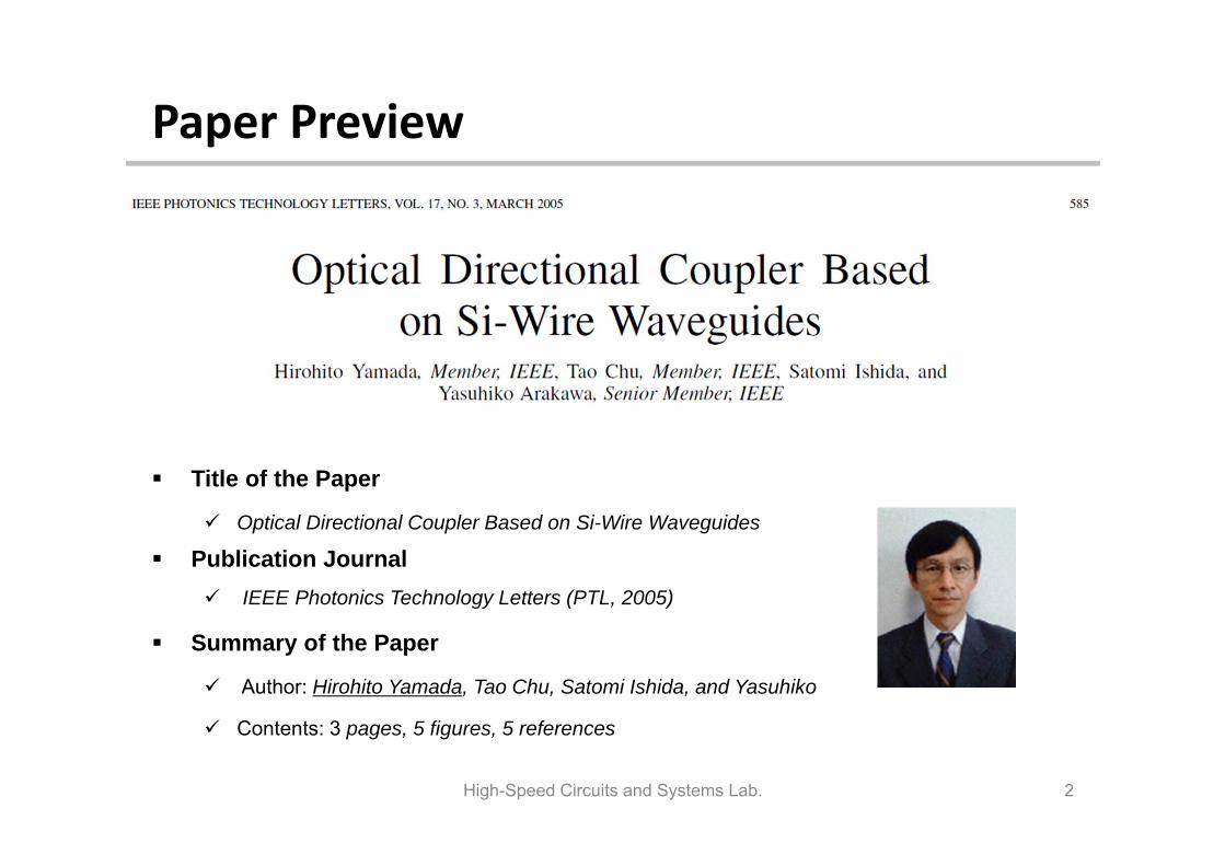
Title of the Paper
Optical Directional Coupler Based on Si-Wire Waveguides
Publication Journal IEEE Photonics Technology Letters (PTL, 2005)
Summary of the Paper
Author: Hirohito Yamada, Tao Chu, Satomi Ishida, and Yasuhiko
Contents: 3 pages, 5 figures, 5 references
High-Speed Circuits and Systems Lab. 2
Contents
1. Introduction1) Concept of Directional Couplers (DCs)2) Theorem of Directional Couplers (DCs)
2. Structure and Fabrication
3. Characteristics1) Simulation Results2) Measurement Results
4. Conclusion
5. References
High-Speed Circuits and Systems Lab. 3
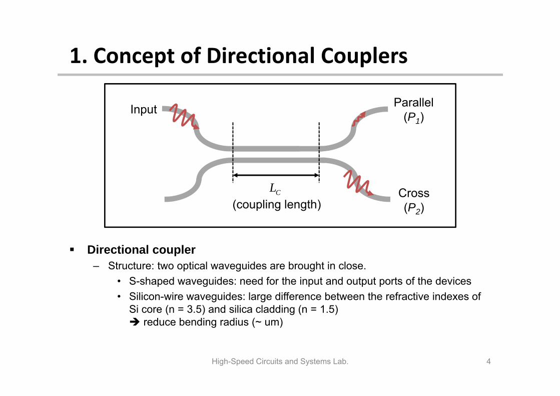
1. Concept of Directional Couplers
Directional coupler– Structure: two optical waveguides are brought in close.
• S-shaped waveguides: need for the input and output ports of the devices• Silicon-wire waveguides: large difference between the refractive indexes of
Si core (n = 3.5) and silica cladding (n = 1.5) reduce bending radius (~ um)
High-Speed Circuits and Systems Lab. 4
Input
CL Cross(P2)
Parallel(P1)
(coupling length)
1. Theorem of Directional Couplers
High-Speed Circuits and Systems Lab. 5
Input
Cross(P2)
Parallel(P1)
Ce o
L
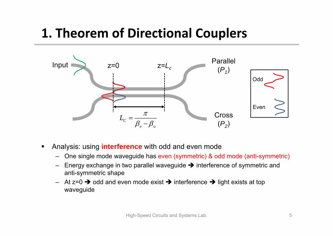
Analysis: using interference with odd and even mode– One single mode waveguide has even (symmetric) & odd mode (anti-symmetric)– Energy exchange in two parallel waveguide interference of symmetric and
anti-symmetric shape– At z=0 odd and even mode exist interference light exists at top
waveguide
Odd
Even
z=0 z=Lc
1. Theorem of Directional Couplers
High-Speed Circuits and Systems Lab. 6
Input
Cross(P2)
Parallel(P1)
Ce o
L
Odd
Even
z=0 z=Lc
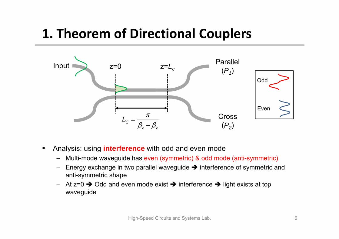
Analysis: using interference with odd and even mode– Multi-mode waveguide has even (symmetric) & odd mode (anti-symmetric)– Energy exchange in two parallel waveguide interference of symmetric and
anti-symmetric shape– At z=0 Odd and even mode exist interference light exists at top
waveguide
1. Theorem of Directional Couplers
High-Speed Circuits and Systems Lab. 7
Input
Cross(P2)
Parallel(P1)
Ce o
L
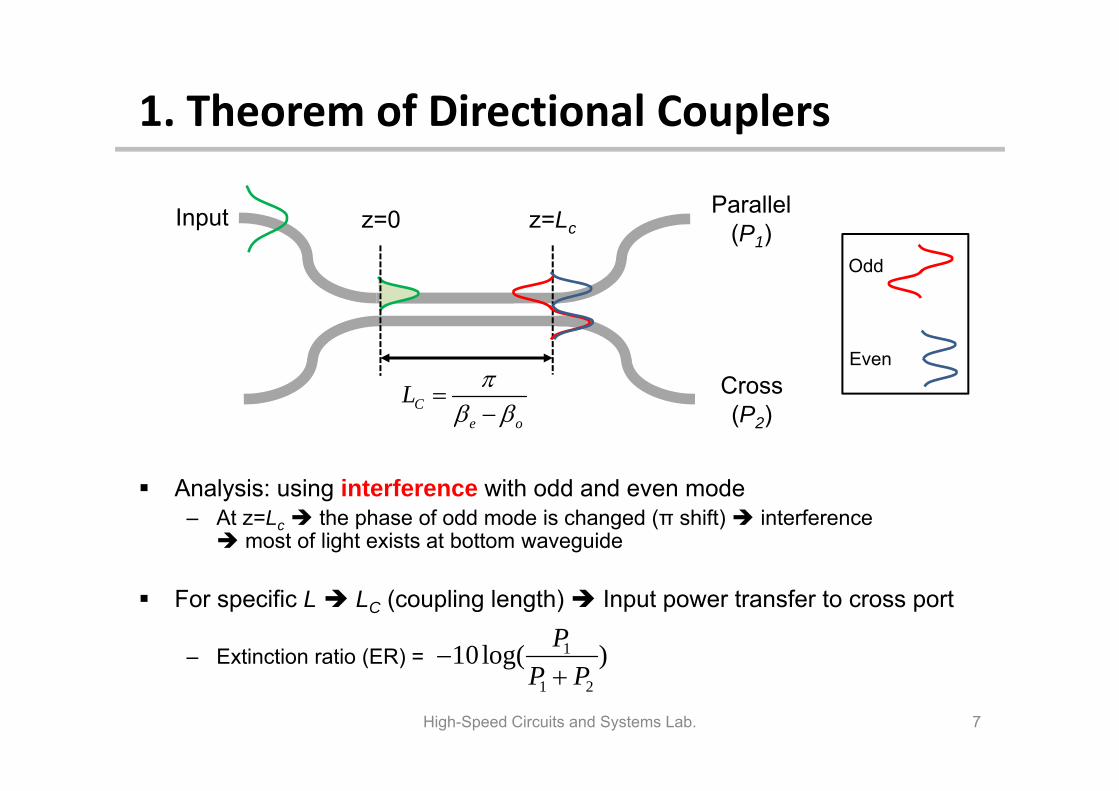
Analysis: using interference with odd and even mode– At z=Lc the phase of odd mode is changed (π shift) interference most of light exists at bottom waveguide
For specific L LC (coupling length) Input power transfer to cross port
– Extinction ratio (ER) =
Odd
Even
1
1 2
10 log( )PP P
z=0 z=Lc
1. Theorem of Directional Couplers
High-Speed Circuits and Systems Lab. 8
Input
Cross(P2)
Parallel(P1)
Ce o
L
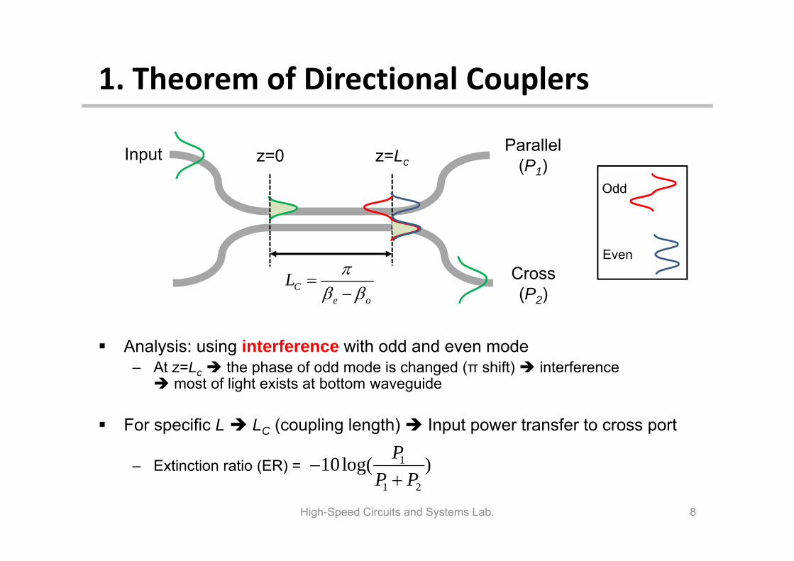
Analysis: using interference with odd and even mode– At z=Lc the phase of odd mode is changed (π shift) interference most of light exists at bottom waveguide
For specific L LC (coupling length) Input power transfer to cross port
– Extinction ratio (ER) =
Odd
Even
1
1 2
10 log( )PP P
z=0 z=Lc
1. Introduction
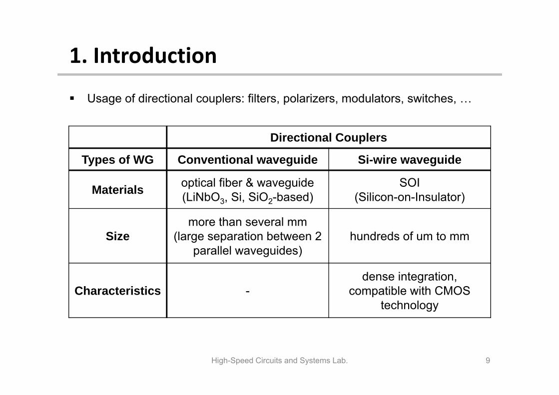
Usage of directional couplers: filters, polarizers, modulators, switches, …
High-Speed Circuits and Systems Lab. 9
Directional Couplers
Types of WG Conventional waveguide Si-wire waveguide
Materials optical fiber & waveguide (LiNbO3, Si, SiO2-based)
SOI (Silicon-on-Insulator)
Sizemore than several mm
(large separation between 2 parallel waveguides)
hundreds of um to mm
Characteristics -dense integration,
compatible with CMOS technology
1. Introduction
Detailed studies on directional couplers with Si-wire waveguides have not yet been reported
In this paper,– Present optical DCs based on Si-wire waveguides– Discuss their characteristics– Describe structure, the fabrication process, calculated and measured results
High-Speed Circuits and Systems Lab. 10
2. Structure and Fabrication
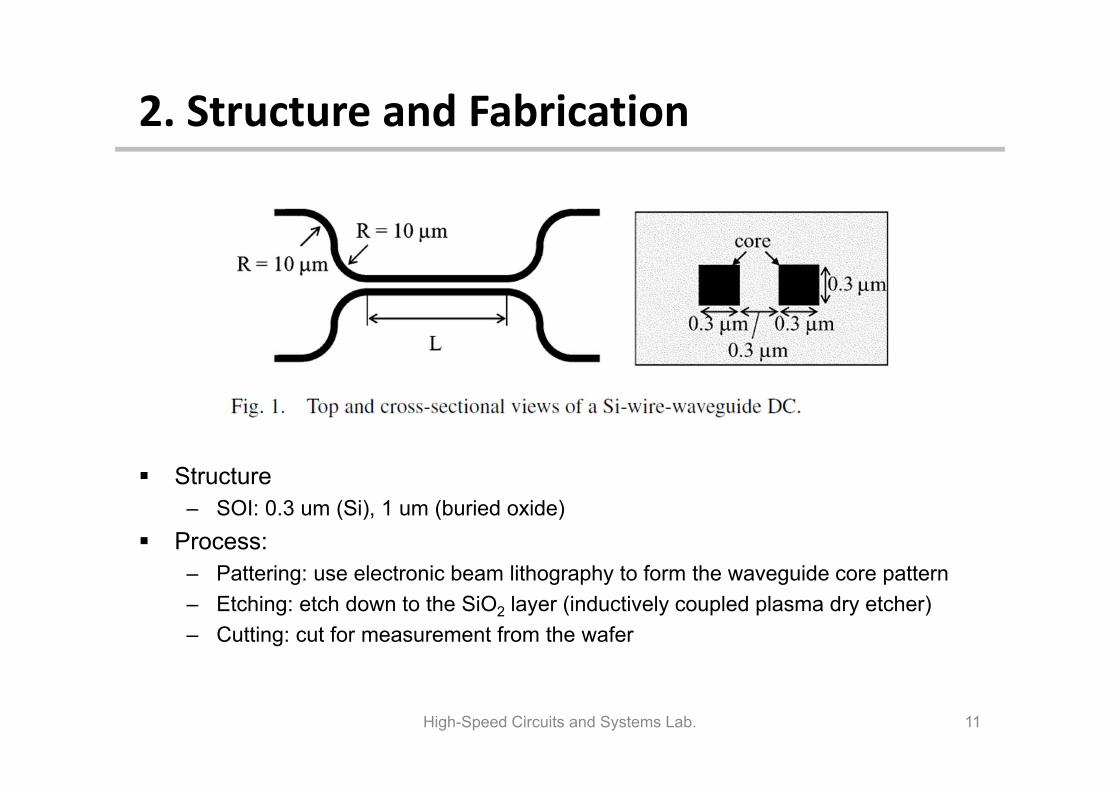
Structure– SOI: 0.3 um (Si), 1 um (buried oxide)
Process:– Pattering: use electronic beam lithography to form the waveguide core pattern– Etching: etch down to the SiO2 layer (inductively coupled plasma dry etcher)– Cutting: cut for measurement from the wafer
High-Speed Circuits and Systems Lab. 11
3. Simulation Results
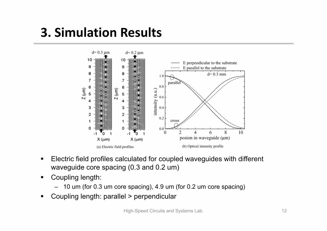
Electric field profiles calculated for coupled waveguides with different waveguide core spacing (0.3 and 0.2 um)
Coupling length: – 10 um (for 0.3 um core spacing), 4.9 um (for 0.2 um core spacing)
Coupling length: parallel > perpendicular
High-Speed Circuits and Systems Lab. 12
3. Measurement Results
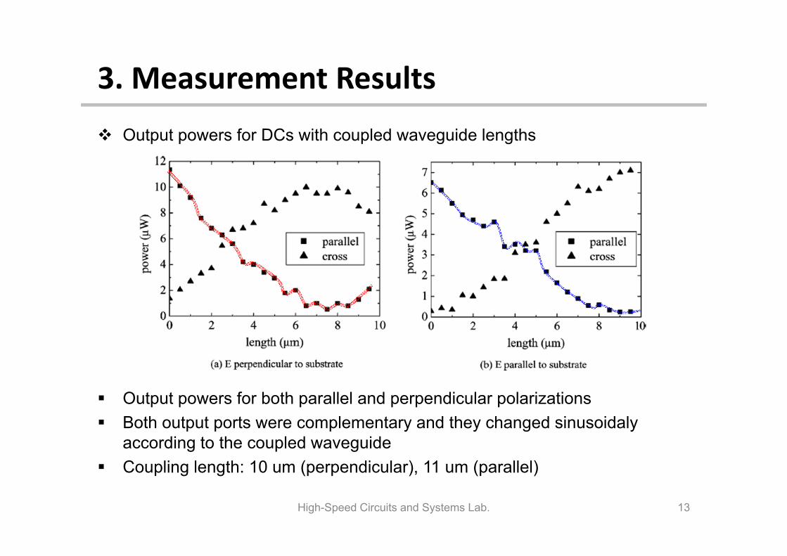
Output powers for both parallel and perpendicular polarizations Both output ports were complementary and they changed sinusoidaly
according to the coupled waveguide Coupling length: 10 um (perpendicular), 11 um (parallel)
High-Speed Circuits and Systems Lab. 13
Output powers for DCs with coupled waveguide lengths
3. Measurement Results
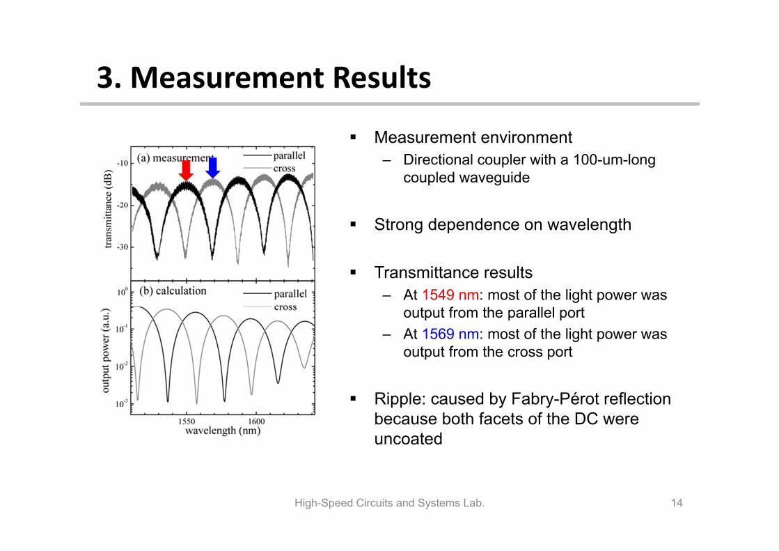
Measurement environment– Directional coupler with a 100-um-long
coupled waveguide
Strong dependence on wavelength
Transmittance results– At 1549 nm: most of the light power was
output from the parallel port– At 1569 nm: most of the light power was
output from the cross port
Ripple: caused by Fabry-Pérot reflection because both facets of the DC were uncoated
High-Speed Circuits and Systems Lab. 14
3. Measurement Results
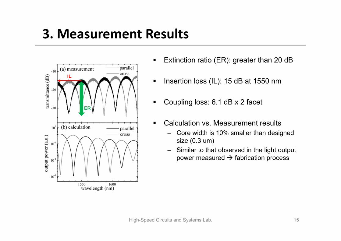
Extinction ratio (ER): greater than 20 dB
Insertion loss (IL): 15 dB at 1550 nm
Coupling loss: 6.1 dB x 2 facet
Calculation vs. Measurement results – Core width is 10% smaller than designed
size (0.3 um)– Similar to that observed in the light output
power measured fabrication process
High-Speed Circuits and Systems Lab. 15
ER
IL
3. Measurement Results
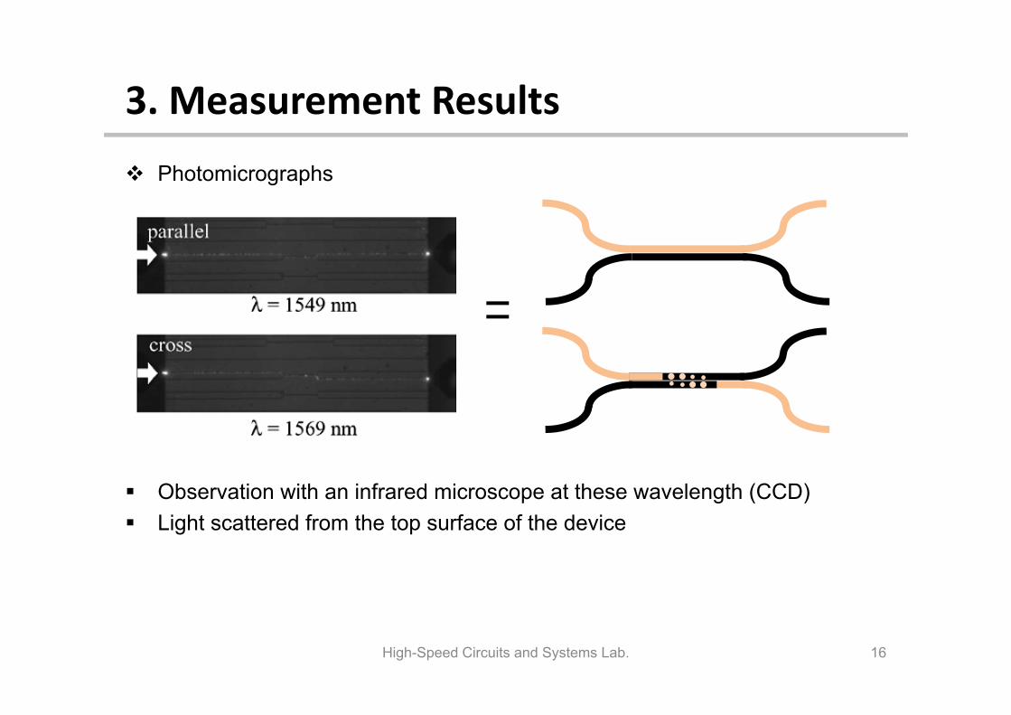
Observation with an infrared microscope at these wavelength (CCD) Light scattered from the top surface of the device
High-Speed Circuits and Systems Lab. 16
Photomicrographs
3. Measurement Results
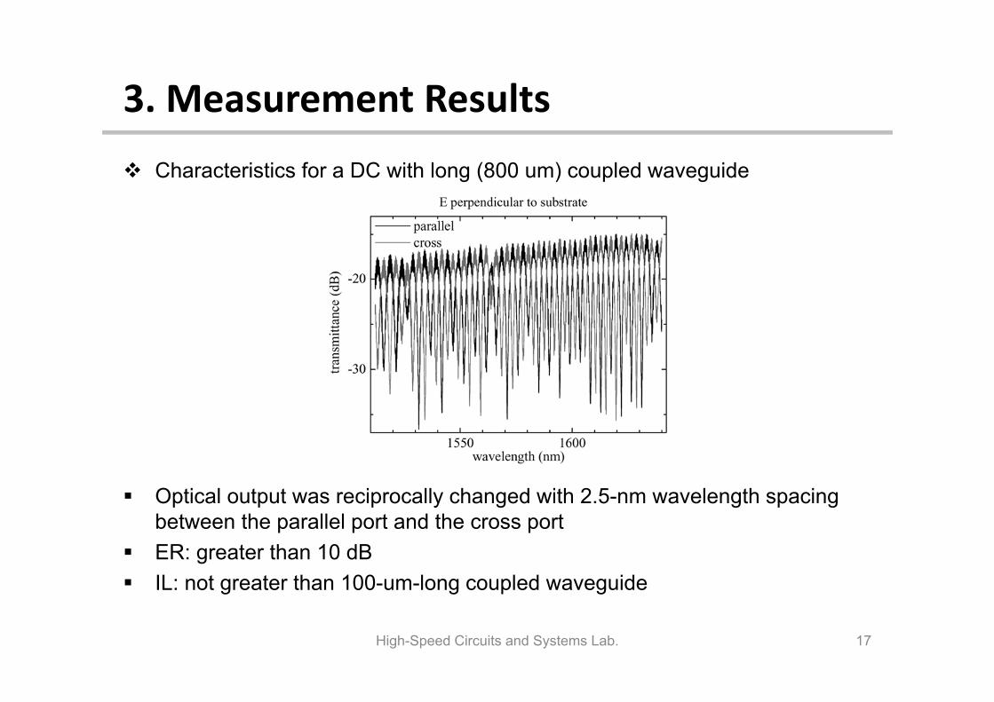
Optical output was reciprocally changed with 2.5-nm wavelength spacing between the parallel port and the cross port
ER: greater than 10 dB IL: not greater than 100-um-long coupled waveguide
High-Speed Circuits and Systems Lab. 17
Characteristics for a DC with long (800 um) coupled waveguide
4. Conclusion
Fabricated optical directional couplers with Si-wire waveguide and evaluated their fundamental characteristics.
Found extremely short coupling lengths (10 um), which means that they can be used as compact power dividers or combiners.
Demonstrated wavelength-selective characteristics of light output from long directional couplers.
Optical outputs from the parallel and cross ports of an 800-um-long device changed reciprocally with a 2.5-nm wavelength periodicity. indicates this device might be used as a wavelength multiplexer-demultiplexer in wavelength-division-multiplexing (WDM) systems.
High-Speed Circuits and Systems Lab. 18
5. References
[1] N. Ofusa, “An optical add-drop multiplexer with a grating-loaded directional coupler in silica waveguides”, IEICE Trans. Commun., vol. E82-B, pp. 1248-1251, 1999
[2] H. Kogelnik, “Switched directional couplers with alternating ∆β”, IEEE J. Quantum Electron, vol. QE-12, no. 7, pp. 396-401, 1976
[3] B. E. Little, “Ultra-compact Si-SiO microring resonator optical channel dropping filters”, IEEE Photon. Technol. Lett., vol. 10, no. 4, pp. 549–551, 1998
[4] A. Sakai, “Propagation characteristics of ultrahigh-∆ optical waveguide on silicon-on-insulator substrate”, Jpn. J. Appl. Phys., vol. 40, pp. L383–L385, 2001.
[5] K. Yamada, “Silicon-wire based ultra small lattice filters with wide free spectral ranges”, Opt. Lett., vol. 28, pp. 1663–1664, 2003.
High-Speed Circuits and Systems Lab. 19
Thank you for listening!
Q & AJeong-Min Lee
High-Speed Circuits and Systems Lab. 20