Embed Size (px)
Citation preview
Optics and Photonics Journal, 2013, 3, 240-249 http://dx.doi.org/10.4236/opj.2013.33039 Published Online July 2013 (http://www.scirp.org/journal/opj)
Optical Image Compression Using a Real Fourier Plane
Abdulsalam G. Alkholidi Faculty of Engineering, Electrical Engineering Department, Sanaa University, Sanaa, Yemen
Email: [email protected]
Received April 7, 2013; revised May 7, 2013; accepted May 17, 2013
Copyright © 2013 Abdulsalam G. Alkholidi. This is an open access article distributed under the Creative Commons Attribution Li-cense, which permits unrestricted use, distribution, and reproduction in any medium, provided the original work is properly cited.
ABSTRACT
Hastening transmission by efficiently providing compression is our goal in this work. Image compression consists in reducing information size representing an image. Elimination of redundancies and non-pertinent information enables memory space minimization and thus fast data transmission. Optics can offer an alternative choice to overcome the limitation of numerical compression algorithms. In this paper, we propose real-time optical image compression using a real Fourier plane to save time required for compression by using the principles of coherent optics. Digital and optical simulation results are presented and analyzed. An optical compression decompression setup is demonstrated using two different SLMs (SEIKO and DisplayTech). The purpose of this method is to simplify our earlier method, improve the quality of reconstructed image, and avoid the disadvantages of numerical algorithms. Keywords: FT; Optical Compression; a Real Fourier Plane; Hologram; SLM
1. Introduction
In recent years, there has been much interest in image compression algorithms which are proposed in this paper. Our algorithm is oriented towards large size images. The goal of this work is to minimize the time required for compression with high compression ratio (Cr). One of the current technological challenges in image compression is to achieve real-time imaging rates with a minimal sacri- fice in signal-to-noise ratio (SNR) [1]. We propose a no- vel technique of image compression using a real Fourier- plane capable of real-time image compression. In the frame of the present work our objective is to simplify our earlier optical image compression algorithm using the JPEG and optical JPEG standards [2]. We intend to eliminate the most complex part in the synoptic diagrams of the set up implementation compression and decom- pression described in [2,3].
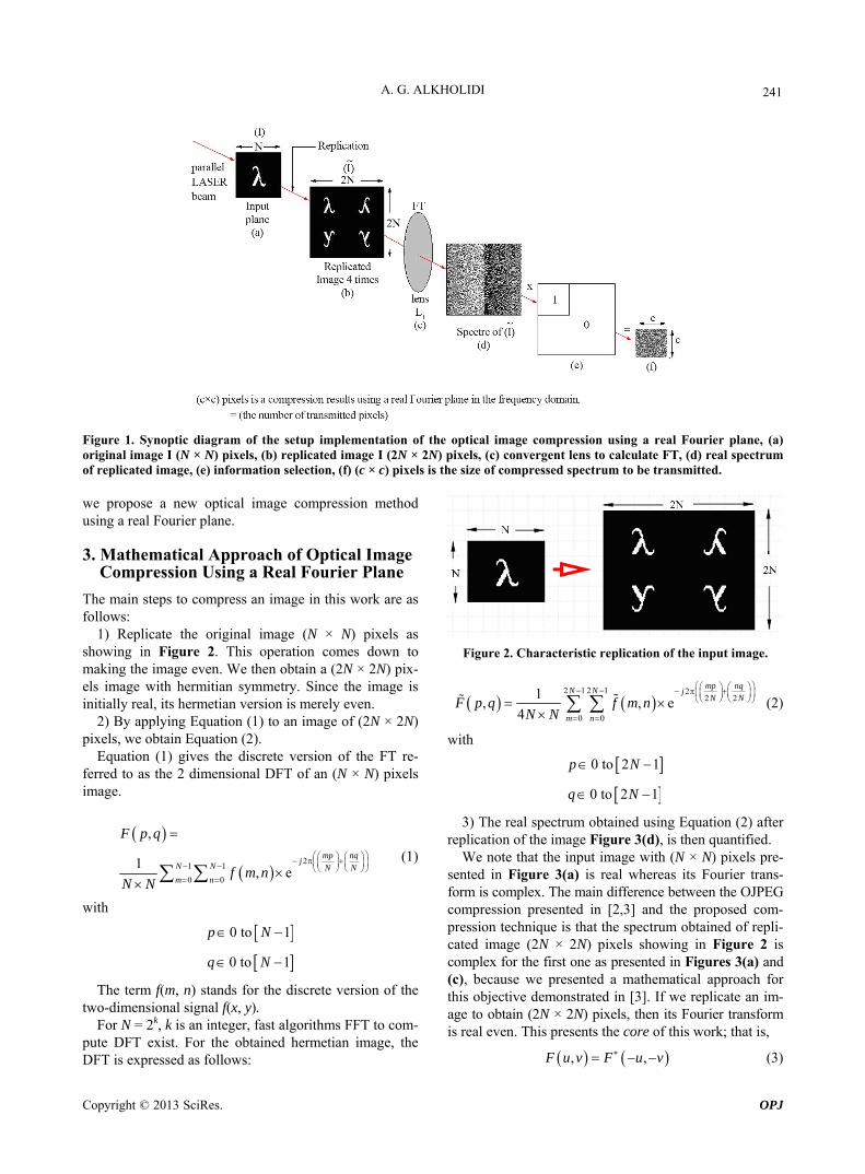
To digitally decompress large images, they should be first transmitted to a calculator to enable applying one or several digital compression methods. The real-life appli- cation of this technique; consists first in optically com- pressing these images. Starting from an image, with size (N × N) pixels (Figure 1(a)), we obtain a compressed version of only (c × c) pixels as pointed out by Figure 1(f). This results in a decrease of the volume of informa- tion to be transmitted to the calculator. The latter may provide additional compression, by applying digital me- thods. In this paper, we provide a detailed technical de-
scription of the proposed architecture. This exposition is interested to serve as a reader-friendly starting point for those interested in learning about optical JPEG com- pression. Although many details are included in our pre- sentation, some details were necessarily omitted to focus on the main subject that is compression. The reader should, therefore, refer to standards of optical JPEG compression [2,3] before attempting an implementation. Indeed, much work has been done toward developing compression methods, most techniques reported, such as presented in [4-8].
The remainder of this paper is structured as follows: Section 2 provides a brief overview of the optical JPEG standards. This is followed, in Section 3, by a detailed description of mathematical approach of the proposed algorithm. In Section 4, optical architecture of compres- sion/decompression is presented. Section 5, an optical setup of image compression/decompression of proposed method is presented and the results are presented in Sec- tion 6. Finally, we conclude with some closing remarks in Section 7.
2. Optical JPEG Compression
By using the principle of coherent optics, optical JPEG (OJPEG) compression and decompression; process the whole image at once and do not divide it into blocks. The disadvantage of OJPEG is the fact that its optical imple- mentation is complicated [2,3]. To relax this constraint,
Copyright © 2013 SciRes. OPJ
A. G. ALKHOLIDI 241
Figure 1. Synoptic diagram of the setup implementation of the optical image compression using a real Fourier plane, (a) original image I (N × N) pixels, (b) replicated image I (2N × 2N) pixels, (c) convergent lens to calculate FT, (d) real spectrum of replicated image, (e) information selection, (f) (c × c) pixels is the size of compressed spectrum to be transmitted. we propose a new optical image compression method using a real Fourier plane.
3. Mathematical Approach of Optical Image Compression Using a Real Fourier Plane
The main steps to compress an image in this work are as follows:
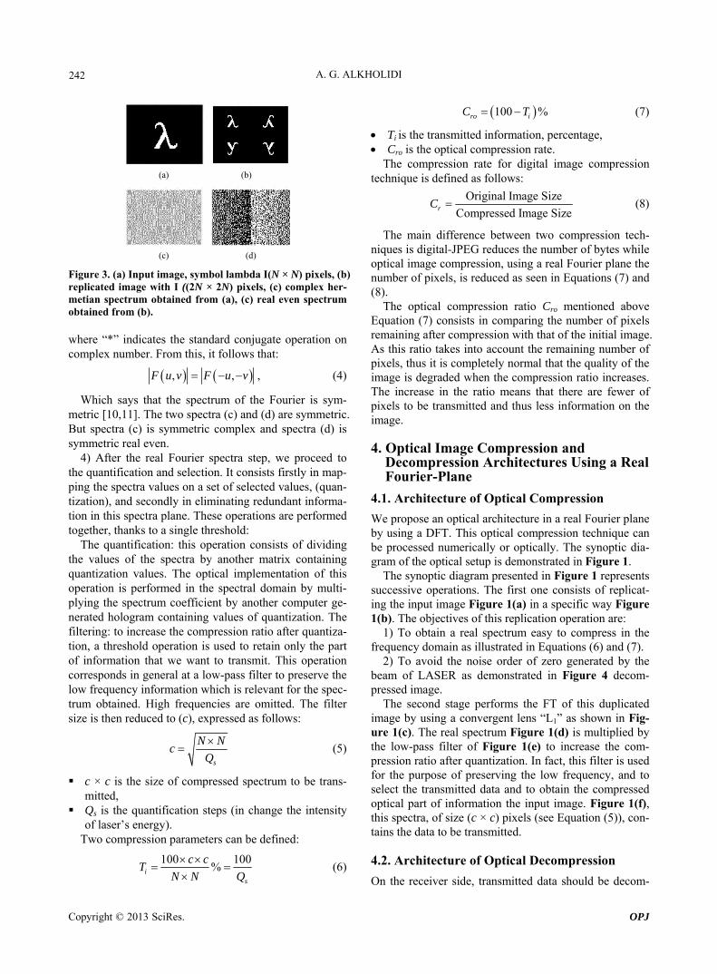
1) Replicate the original image (N × N) pixels as showing in Figure 2. This operation comes down to making the image even. We then obtain a (2N × 2N) pix- els image with hermitian symmetry. Since the image is initially real, its hermetian version is merely even.
2) By applying Equation (1) to an image of (2N × 2N) pixels, we obtain Equation (2).
Equation (1) gives the discrete version of the FT re- ferred to as the 2 dimensional DFT of an (N × N) pixels image.
2
1 1
0 0
,
1, e
mp nqj
N N N N
m n
F p q
f m nN N
(1)
with
0 to 1p N
0 to 1q N
The term f(m, n) stands for the discrete version of the two-dimensional signal f(x, y).
For N = 2k, k is an integer, fast algorithms FFT to com- pute DFT exist. For the obtained hermetian image, the DFT is expressed as follows:
Figure 2. Characteristic replication of the input image.
2 1 2 1 2
2 2
0 0
1, , e
4
mp nqN N jN N
m n
F p q f m nN N
(2)
with
0 to 2 1p N
0 to 2 1q N
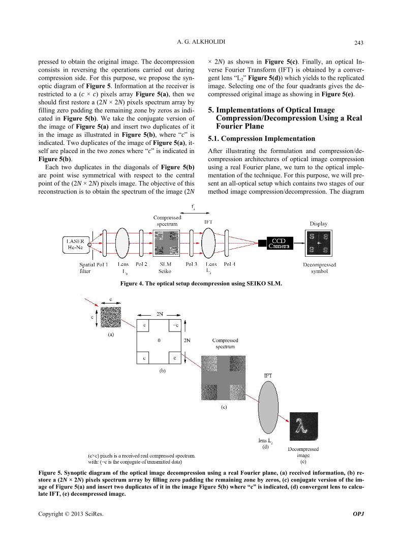
3) The real spectrum obtained using Equation (2) after replication of the image Figure 3(d), is then quantified.
We note that the input image with (N × N) pixels pre- sented in Figure 3(a) is real whereas its Fourier trans- form is complex. The main difference between the OJPEG compression presented in [2,3] and the proposed com- pression technique is that the spectrum obtained of repli- cated image (2N × 2N) pixels showing in Figure 2 is complex for the first one as presented in Figures 3(a) and (c), because we presented a mathematical approach for this objective demonstrated in [3]. If we replicate an im- age to obtain (2N × 2N) pixels, then its Fourier transform is real even. This presents the core of this work; that is,
, ,F u v F u v (3)
Copyright © 2013 SciRes. OPJ
A. G. ALKHOLIDI 242
(a) (b)
(c) (d)
Figure 3. (a) Input image, symbol lambda I(N × N) pixels, (b) replicated image with I ((2N × 2N) pixels, (c) complex her-metian spectrum obtained from (a), (c) real even spectrum obtained from (b). where “*” indicates the standard conjugate operation on complex number. From this, it follows that:
, ,F u v F u v , (4)
Which says that the spectrum of the Fourier is sym-metric [10,11]. The two spectra (c) and (d) are symmetric. But spectra (c) is symmetric complex and spectra (d) is symmetric real even.
4) After the real Fourier spectra step, we proceed to the quantification and selection. It consists firstly in map- ping the spectra values on a set of selected values, (quan- tization), and secondly in eliminating redundant informa- tion in this spectra plane. These operations are performed together, thanks to a single threshold:
The quantification: this operation consists of dividing the values of the spectra by another matrix containing quantization values. The optical implementation of this operation is performed in the spectral domain by multi- plying the spectrum coefficient by another computer ge- nerated hologram containing values of quantization. The filtering: to increase the compression ratio after quantiza- tion, a threshold operation is used to retain only the part of information that we want to transmit. This operation corresponds in general at a low-pass filter to preserve the low frequency information which is relevant for the spec- trum obtained. High frequencies are omitted. The filter size is then reduced to (c), expressed as follows:
s
N Nc
Q
(5)
c × c is the size of compressed spectrum to be trans-mitted,
Qs is the quantification steps (in change the intensity of laser’s energy).
Two compression parameters can be defined:
100 100%i
s
c cT
N N Q
100 %ro iC T (7)
Ti is the transmitted information, percentage, Cro is the optical compression rate.
The compression rate for digital image compression technique is defined as follows:
Original Image Size
Compressed Image SizerC (8)
The main difference between two compression tech-niques is digital-JPEG reduces the number of bytes while optical image compression, using a real Fourier plane the number of pixels, is reduced as seen in Equations (7) and (8).
The optical compression ratio Cro mentioned above Equation (7) consists in comparing the number of pixels remaining after compression with that of the initial image. As this ratio takes into account the remaining number of pixels, thus it is completely normal that the quality of the image is degraded when the compression ratio increases. The increase in the ratio means that there are fewer of pixels to be transmitted and thus less information on the image.
4. Optical Image Compression and Decompression Architectures Using a Real Fourier-Plane
4.1. Architecture of Optical Compression
We propose an optical architecture in a real Fourier plane by using a DFT. This optical compression technique can be processed numerically or optically. The synoptic dia- gram of the optical setup is demonstrated in Figure 1.
The synoptic diagram presented in Figure 1 represents successive operations. The first one consists of replicat- ing the input image Figure 1(a) in a specific way Figure 1(b). The objectives of this replication operation are:
1) To obtain a real spectrum easy to compress in the frequency domain as illustrated in Equations (6) and (7).
2) To avoid the noise order of zero generated by the beam of LASER as demonstrated in Figure 4 decom-pressed image.
The second stage performs the FT of this duplicated image by using a convergent lens “L1” as shown in Fig- ure 1(c). The real spectrum Figure 1(d) is multiplied by the low-pass filter of Figure 1(e) to increase the com- pression ratio after quantization. In fact, this filter is used for the purpose of preserving the low frequency, and to select the transmitted data and to obtain the compressed optical part of information the input image. Figure 1(f), this spectra, of size (c × c) pixels (see Equation (5)), con- tains the data to be transmitted.
4.2. Architecture of Optical Decompression (6) On the receiver side, transmitted data should be decom-
Copyright © 2013 SciRes. OPJ
A. G. ALKHOLIDI
Copyright © 2013 SciRes. OPJ
243
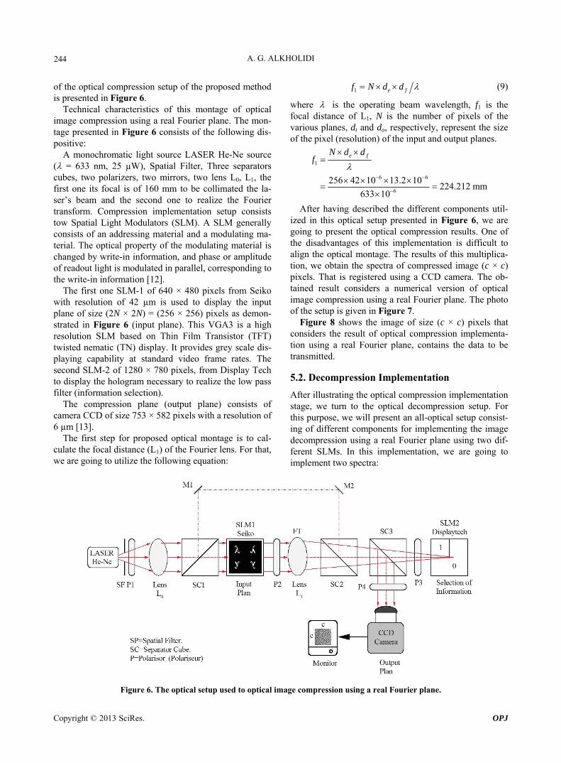
pressed to obtain the original image. The decompression consists in reversing the operations carried out during compression side. For this purpose, we propose the syn- optic diagram of Figure 5. Information at the receiver is restricted to a (c × c) pixels array Figure 5(a), then we should first restore a (2N × 2N) pixels spectrum array by filling zero padding the remaining zone by zeros as indi- cated in Figure 5(b). We take the conjugate version of the image of Figure 5(a) and insert two duplicates of it in the image as illustrated in Figure 5(b), where “c” is indicated. Two duplicates of the image of Figure 5(a), it- self are placed in the two zones where “c” is indicated in Figure 5(b).
Each two duplicates in the diagonals of Figure 5(b) are point wise symmetrical with respect to the central point of the (2N × 2N) pixels image. The objective of this reconstruction is to obtain the spectrum of the image (2N
× 2N) as shown in Figure 5(c). Finally, an optical In-verse Fourier Transform (IFT) is obtained by a conver-gent lens “L2” Figure 5(d)) which yields to the replicated image. Selecting one of the four quadrants gives the de-compressed original image as showing in Figure 5(e).
5. Implementations of Optical Image Compression/Decompression Using a Real Fourier Plane
5.1. Compression Implementation
After illustrating the formulation and compression/de- compression architectures of optical image compression using a real Fourier plane, we turn to the optical imple- mentation of the technique. For this purpose, we will pre- sent an all-optical setup which contains two stages of our method image compression/decompression. The diagram
Figure 4. The optical setup decompression using SEIKO SLM.
Figure 5. Synoptic diagram of the optical image decompression using a real Fourier plane, (a) received information, (b) re-store a (2N × 2N) pixels spectrum array by filling zero padding the remaining zone by zeros, (c) conjugate version of the im-age of Figure 5(a) and insert two duplicates of it in the image Figure 5(b) where “c” is indicated, (d) convergent lens to calcu-late IFT, (e) decompressed image.
A. G. ALKHOLIDI 244
of the optical compression setup of the proposed method is presented in Figure 6.
Technical characteristics of this montage of optical image compression using a real Fourier plane. The mon- tage presented in Figure 6 consists of the following dis- positive:
A monochromatic light source LASER He-Ne source ( = 633 nm, 25 µW), Spatial Filter, Three separators cubes, two polarizers, two mirrors, two lens L0, L1, the first one its focal is of 160 mm to be collimated the la- ser’s beam and the second one to realize the Fourier transform. Compression implementation setup consists tow Spatial Light Modulators (SLM). A SLM generally consists of an addressing material and a modulating ma- terial. The optical property of the modulating material is changed by write-in information, and phase or amplitude of readout light is modulated in parallel, corresponding to the write-in information [12].
The first one SLM-1 of 640 × 480 pixels from Seiko with resolution of 42 µm is used to display the input plane of size (2N × 2N) = (256 × 256) pixels as demon- strated in Figure 6 (input plane). This VGA3 is a high resolution SLM based on Thin Film Transistor (TFT) twisted nematic (TN) display. It provides grey scale dis- playing capability at standard video frame rates. The second SLM-2 of 1280 × 780 pixels, from Display Tech to display the hologram necessary to realize the low pass filter (information selection).
The compression plane (output plane) consists of camera CCD of size 753 × 582 pixels with a resolution of 6 µm [13].
The first step for proposed optical montage is to cal- culate the focal distance (L1) of the Fourier lens. For that, we are going to utilize the following equation:
1 e ff N d d (9)
where is the operating beam wavelength, f1 is the focal distance of L1, N is the number of pixels of the various planes, di and do, respectively, represent the size of the pixel (resolution) of the input and output planes.
1
6 6
6
256 42 10 13.2 10224.212 mm
633 10
e fN d df
After having described the different components util- ized in this optical setup presented in Figure 6, we are going to present the optical compression results. One of the disadvantages of this implementation is difficult to align the optical montage. The results of this multiplica- tion, we obtain the spectra of compressed image (c × c) pixels. That is registered using a CCD camera. The ob- tained result considers a numerical version of optical image compression using a real Fourier plane. The photo of the setup is given in Figure 7.
Figure 8 shows the image of size (c × c) pixels that considers the result of optical compression implementa- tion using a real Fourier plane, contains the data to be transmitted.
5.2. Decompression Implementation
After illustrating the optical compression implementation stage, we turn to the optical decompression setup. For this purpose, we will present an all-optical setup consist- ing of different components for implementing the image decompression using a real Fourier plane using two dif- ferent SLMs. In this implementation, we are going to implement two spectra:
Figure 6. The optical setup used to optical image compression using a real Fourier plane.
Copyright © 2013 SciRes. OPJ

A. G. ALKHOLIDI 245
Figure 7. A photo of the setup used for the optical compression stage.
c
c
Figure 8. The result of optical compression implementation using a real Fourier plane. - Compressed spectrum in grey level as demonstrated
in Figure 4, where, we used SLM SEIKO. - Binary compressed spectrum as demonstrated in Fig-
ure 9, where, we used DisplayTech SLM. We used two SLM with different technical character-
istics to compare the decompressed images. In fact, firstly we used the modulator SEIKO permits to display an image with several levels of grey, but with a weak- level of quality of reconstructed image. Secondly, we used DesplayTech binary modulator that displays reve- nue so important, but it does not permits to the display of the specters with several levels of grey. For this purpose, we propose the synoptic diagram of Figure 4. Informa- tion at the receiver is restricted to (c × c) pixels. Two polarizers are placed before and after the SLM in order to operate in phase. A mask is used to isolate only the addi- tive share of the SLM. The modulator is used to display the hologram that includes (c × c) pixels representing the compressed spectrum of the image obtained digitally (Figures 10(a) and (b)).
6. Results of Optical Implementation
To validate the principle of proposed compression/de- compression method of a real Fourier plane, we have considered several images as shown in Figure 11.
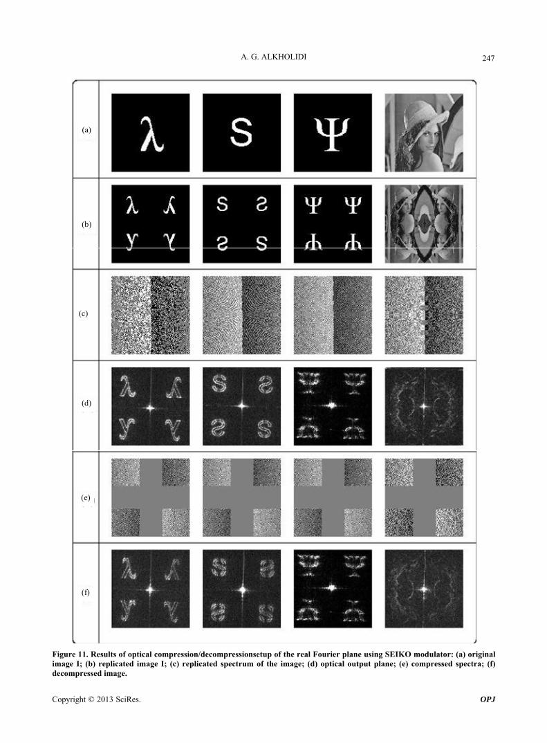
In column (a), we see the different symbols and an image used to validate our optical implementation of compression/decompression stages. Four images are con- sidered including three binary letters images, namely “”, “S”, and “Ψ” and, a gray level image, namely the famous “Lena”. Each input image extends over 128 × 128 pixels. In column (b), we have replicated each input image four times. Indeed, each image is mirrored horizontally, ver- tically and obliquely. In column (c), the calculated Opti- cal Fourier Transform (OFT) of the different replicas is shown. We have optically implemented the IFT of these various spectra. These are used as references. The results are given in column (d). In column (e), we see the dif- ferent compressed spectra with our proposed method. Finally, in column (f) the optically reconstructed versions of decompressed images are shown. The results, shown in column “f”, validate the principle of our implementa- tion method of the optical image compression/decom- pression using a real Fourier plane.
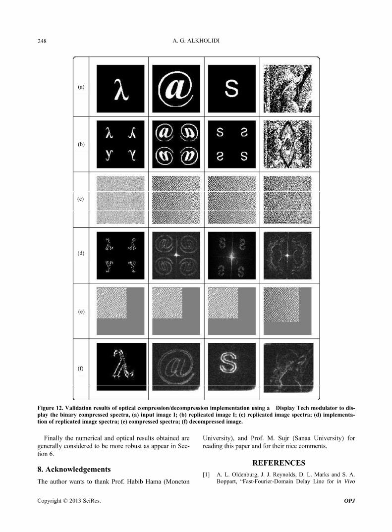
Figure 12 shows the optical implementation of the compression/decompression of proposed method. The in- put plane of this setup consists of a binary modulator DisplayTech to display the binary compressed spectra as demonstrated in Figure 12(e), (a) original image; (b) replicated image; (c) replicated image spectra; (d) optical output plane of the replicated image spectra; (e) com- pressed spectra; (f) decompressed image. Finally, we
Copyright © 2013 SciRes. OPJ

A. G. ALKHOLIDI 246
Figure 9. The optical setup decompression using DisplyTech SLM.
(a) (b)
(c) (d)
Figure 10. An examples of compressed spectra calculated numerically by applying our method, compressed spectra in grey level, (b) binary compressed spectra (c) decompressed symbol (λ) optically for (a), (d) decompressed binary sym- bol of (λ) for (b). note that all optical setups had been realized in depart-ment of optoelectronic, ISEN-Brest, France.
7. Conclusions
In this paper, we have presented a novel method of opti- cal image compression/decompression using a real Fou- rier plane. This optical compression technique processes the image in whole image at once and does not divide it into blocks, thanks to coherent optics. We successively
simplified our earlier optical image compression method OJPEG. The proposed method has shown to be a good compression alternative for all types of images. In the practical part, we proposed two optical architectures: one for compression and another one for decompression. In- deed, we meet several difficulties with set up alignments of laser beam for assuring a multiplication between input plan (displayed over an SLM SEIKO) with low-pass fil- ter whose select the pertinent information displayed over another SLM DisplayTech). In fact, decompressing an image is easy to implement optically where only one SLM is required as demonstrated in Figures 4 and 9. Ac- cording to the above considerations, we successfully proof this novel optical compression/decompression me- thod, reduced the information volume representing an image in pixels. Proposed method has several advantages compared to other algorithms. We can list the main fea- tures of proposed method according to obtained results: - Minimize the time required for compression/decom-
pression by using the principle of coherent optics. - Gain on space memory. - Improve the quality of reconstructed image numeri-
cally and optically. - Avoid the problem that characterized digital JPEG as
(mosaic effect). - Simplify our earlier compression method optical
JPEG. - Apply this method in combination between numerical
and optical (optical compression and numerical de-compression), we can go ahead for all optics.
Copyright © 2013 SciRes. OPJ
A. G. ALKHOLIDI 247
(a)
(c)
(b)
(d)
(e)
(f)
Figure 11. Results of optical compression/decompressionsetup of the real Fourier plane using SEIKO modulator: (a) original image I; (b) replicated image I; (c) replicated spectrum of the image; (d) optical output plane; (e) compressed spectra; (f) decompressed image.
Copyright © 2013 SciRes. OPJ
A. G. ALKHOLIDI 248
(a)
(c)
(b)
(d)
(e)
(f)
Figure 12. Validation results of optical compression/decompression implementation using a Display Tech modulator to dis-play the binary compressed spectra, (a) input image I; (b) replicated image I; (c) replicated image spectra; (d) implementa-tion of replicated image spectra; (e) compressed spectra; (f) decompressed image.
Finally the numerical and optical results obtained are
generally considered to be more robust as appear in Sec- tion 6.
8. Acknowledgements
The author wants to thank Prof. Habib Hama (Moncton
University), and Prof. M. Sujr (Sanaa University) for reading this paper and for their nice comments.
REFERENCES
[1] A. L. Oldenburg, J. J. Reynolds, D. L. Marks and S. A. Boppart, “Fast-Fourier-Domain Delay Line for in Vivo
Copyright © 2013 SciRes. OPJ
A. G. ALKHOLIDI 249
Optical Coherence Tomography with a Polygonal Scan-ner,” Applied Optics, Vol. 42, No. 22, 2003, pp. 4606- 4611.
[2] A. Alkholidi, A. Alfalou and H. Hamam, “A New Ap- proach for Optical Colored Image Compression Using the JPEG Standards,” Signal Processing, Vol. 87, 2007, pp. 569-583.
[3] A. Alkholidi, “Analyse and Implementation of Compres- sion/Decompression Processors Based on JPEG and JPEG 2000 Standards,” Ph.D. Thesis, Université de Bretagne Ocedentale (UBO), Brest, 2007.
[4] A. Alkholidi, A. Cottour, A. Al falou, H. Hamam and G. Keryer, “Real Time Optical 2-D Wavelet Transform Based of the JPEG2000 Standards,” European Physical Journal (EPJ), Applied Physics, Vol. 44, 2008, pp. 261- 272.
[5] A. Alfalou, et al., “Assessing the Performance of a Me- thod of Simultaneous Compression and Encryption of Multiple Images and Its Resistance against Various At-tacks,” Optics Express, Vol. 21, No. 7, 2013, pp. 8025- 8043. doi:10.1364/OE.21.008025
[6] A. E. Shortt, T. J. Naughton and B. Javidi, “Compression of Optically Encrypted Digital Holograms Using Artifi- cial Neural Networks,” Journal of Display Technology,
Vol. 2, No. 4, 2006, pp. 401-410.
[7] C.-H. Chuang and Y.-L. Chen, “Steganographic Optical Image Encryption System Based on Reversible Data Hi- ding and Double Random Phase Encoding,” Optical En- gineering, Vol. 52, No. 2, 2013, Article ID: 028201.
[8] X. Q. Zhou, et al., “Spatial-Frequency-Compression Scheme for Diffuse Tomography with Dataset,” Applied Optics, Vol. 52, No. 9, 2013, pp. 1779-1792.
[9] H. Wang, S. S. Han and M. Kolobov, “Quantum Limits in Compressed Sensing of Optical Images,” Quantum Elec- tronics and Laser Science Conference, San Jose, 6 May 2012.
[10] R. C. Gonzalez and R. E. Woods, “Digital Image Com- pression,” Prentice Hall, 2009.
[11] W. Goodman, “Introduction to Fourier Optics,” MacGraw- Hill, New York, 1968.
[12] Y. Suzuki, “Spatial Light Modulators for Phase-Only Modulation,” IEEE, 1999, pp. 1312-1313.
[13] G. Ntogari, et al., “A Numerical Study of Optical Swit- ches and Modulators Based on Ferroelectronic Liquid Crystals,” Journal of Optics A: Pure and Applied Optics, Vol. 7, 2004, pp. 82-87.
Copyright © 2013 SciRes. OPJ


![light.ece.illinois.edulight.ece.illinois.edu/ECE460/PDF/Microscopy_notes.docx · Web viewfocal plane the Fourier transform of the field distribution at its front focal plane [1, 2]](https://img.pdfslide.net/doc/110x75/5e458c6f0191c127344b7773/lightece-web-view-focal-plane-the-fourier-transform-of-the-field-distribution.jpg)


![Focal plane array detector-based micro-Fourier-transform ......[47,57] Spectroscopic techniques like Raman spectroscopy[22,27,46,58] and especially Fourier-transform infrared (FTIR)](https://img.pdfslide.net/doc/110x75/5f6fffd1a1b87878030738c3/focal-plane-array-detector-based-micro-fourier-transform-4757-spectroscopic.jpg)