Embed Size (px)
Citation preview

1
ECE/OPTI 531 – Image Processing Lab for Remote Sensing Fall 2005
Optical Radiation Models
Reading: Chapter 2
Fall 2005Optical Radiation Models 2
Optical Radiation Models
• Energy Sources• VSWIR Modeling• MWIR-LWIR Modeling

2
Fall 2005Optical Radiation Models 3
Quantifying Radiation
• Radiant energy (Q in joules) is a measure of the capacityof an EM wave to do work by moving an object, heating,or changing its state.
• Radiant flux (Φ in watts) is the time rate (flow) of energypassing through a certain location.
• Radiant flux density (watts/m2) is the flux intercepted bya planar surface of unit area.– Irradiance (E) is flux density incident upon a surface.– Exitance (M) or emittance is flux density leaving a surface.
• The solid angle (Ω in steradians) subtended by an area Aon a spherical surface of radius r is A/r2.– Radiant intensity (I in watts/sr) is the flux per unit solid
angle in a given direction.– Radiance (L in watts/m2/sr) is the intensity per unit
projected area.• Radiance from source to object is conserved!
Fall 2005Optical Radiation Models 4
0
500
1000
1500
2000
2500
0.4 0.8 1.2 1.6 2 2.4
5900K BB at earth-sun distance
MODTRAN
irra
dia
nce
(W
-m-2
-µm
-1)
wavelength (µm)
solar spectrum and blackbody approximation
Spectral Radiant Exitance• Spectral distribution of radiation flux• Planck’s equation (Eq. 2–1) for perfect radiator
(blackbody)
– T is the blackbody’s temperature in Kelvin (K),T=5900K for sun, 300K for Earth,
• Mλ is a function of both wavelength of radiationand temperature of the source– usually plotted as function of wavelength, for given
temperature

3
Fall 2005Optical Radiation Models 5
Three Spectral Regions
• VSWIR (Visible-ShortWave IR, 0.4 to 2.4µm, 400to 2400nm)– Solar radiation dominates
• MWIR (MidWave IR, 3 to 5µm, 3000 to 5000nm)– Mixture of solar and thermal radiation
• LWIR (LongWave IR, 8 to 14µm, 8000 to14000nm)– Thermal radiation dominates– Emitted by objects on Earth’s surface as a function of
their temperature and emissivity
Fall 2005Optical Radiation Models 6
Optical Radiation Models
• Energy Sources• VSWIR Modeling• MWIR-LWIR Modeling

4
Fall 2005Optical Radiation Models 7
sensor
!
IFOV
!
L"sp
E"
L"su
L"sd
nadir
E"0
down-scatteredunscattered path-scattered
surface-reflected
direct skylightpath
radiance
Top-Of-the-Atmosphere (TOA)
VSWIR Modeling
• Three components reach sensor– Direct component is unscattered from source– Skylight is scattered down onto the target (Why are
shadows not black?)– Path radiance is scattered along path up into the
sensor
Fall 2005Optical Radiation Models 8
Direct Component
• Related to the signal of interest, i.e. surface reflectance• Top-Of-the-Atmosphere (TOA) irradiance modified by
atmospheric transmittance along solar path
• Earth surface irradiance depends on the angleof incidence, which in-turn, depends on solar angle andtopography
0
0.2
0.4
0.6
0.8
1
0.4 0.8 1.2 1.6 2 2.4
tran
smit
tance
wavelength (µm)
CO2
H2O
H2O
H2O
H2O
CO2
CO2
CO2,
H2O
CO2,
Normal to solar path:
Earth surface:

5
Fall 2005Optical Radiation Models 9
irradiance at earth surface
view vector (to sensor)
(x,y)
incident irradiance does not depend on the view angle, φ
surface normal vector
solar vector (to sun)
solar elevation angle α
flux density normal to solar path
flux density at earth surfaceflux is spread over
larger area at earth surface
solar incident angle θ
view angle φ
Fall 2005Optical Radiation Models 10
Example: Shaded Relief
• Solar incident angle– solar elevation– local topography
(slope, aspect)• Simulate incident
angle effect onirradiance– calculate cos[θ(x,y)]
for every pixel at(x,y) using solarelevation angle fromTM image and DEM —>“shaded-relief” image
digital elevation model (DEM) shaded-relief image
TM image contrast-stretched TM image

6
Fall 2005Optical Radiation Models 11
self-shadowed pixels projected shadows
total shadowed area = union(self-shadowed area, projected shadow area)
Shadowing
• Another incident geometry effect
Fall 2005Optical Radiation Models 12
Temporal Changes
October 20, 1980June 11, 1981
shading and shadowing 5 months apartLandsat MSS image of Grand Canyon, AZ
7
Fall 2005Optical Radiation Models 13
View Path
• Incident irradiance reflects at Earth surface tobecome surface radiance
• Surface radiance modified by atmospherictransmittance along sensor view path tobecome at-sensor radiance
Earth surface:
At-sensor:
Fall 2005Optical Radiation Models 14
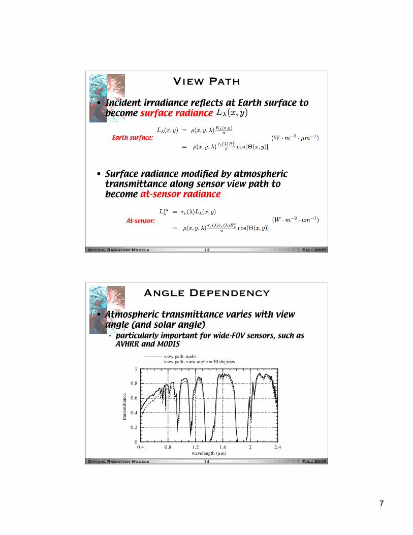
Angle Dependency
• Atmospheric transmittance varies with viewangle (and solar angle)– particularly important for wide-FOV sensors, such as
AVHRR and MODIS
0
0.2
0.4
0.6
0.8
1
0.4 0.8 1.2 1.6 2 2.4
view path, nadirview path, view angle = 40 degrees
tran
smit
tance
wavelength (µm)

8
Fall 2005Optical Radiation Models 15
Direct Component Summary
sensor
Earth surface irradiance
surface radiance
at-sensor radiance
Fall 2005Optical Radiation Models 16
Indirect Components
• Skylight component– secondary signal component
– where F is the fraction of sky visible at a given earthsurface point
• Path radiance component– assumed independent of (x,y) here– atmospheric scattering (“haze”)
• Rayleigh scattering for a clear atmosphere (moleculesonly)
• Mie scattering for an atmosphere with aerosols (watervapor) or particulates (dust, smoke)
• real atmospheres exhibit both Rayleigh and Mie scattering
At-sensor:
At-sensor:

9
Fall 2005Optical Radiation Models 17
Total At-Sensor Radiance
: surface diffuse reflectance (unitless): view path atmospheric transmittance (unitless): solar path atmospheric transmittance (unitless): incident, exo-atmospheric spectral irradiance (W·m-2·µm-1): cosine of angle between solar vector and surface normal: fraction of sky hemisphere visible from surface point: downwelling atmospheric spectral irradiance (W·m-2·µm-1): upwelling atmospheric path spectral radiance
(W·m-2·µm-1 ·sr-1)
Fall 2005Optical Radiation Models 18
MODTRAN Simulation
0
500
1000
1500
2000
2500
0
50
100
150
200
250
400 800 1200 1600 2000 2400
AVIRIS DN
MODTRAN radiance
AV
IRIS
DN
MO
DT
RA
N rad
iance (W
-m-2-sr
-1-µm
-1)
wavelength (nm)
0
20
40
60
80
100
120
0.4 0.8 1.2 1.6 2 2.4
path-scattered
ground-reflected
radia
nce
(W
-m-2
-sr-1
-µm
-1)
wavelength (µm)
10
Fall 2005Optical Radiation Models 19
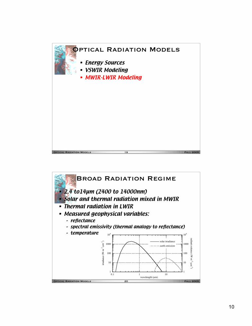
Optical Radiation Models
• Energy Sources• VSWIR Modeling• MWIR-LWIR Modeling
Fall 2005Optical Radiation Models 20
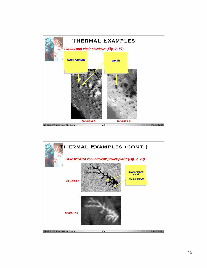
Broad Radiation Regime
• 2.4 to14µm (2400 to 14000nm)• Solar and thermal radiation mixed in MWIR• Thermal radiation in LWIR• Measured geophysical variables:
– reflectance– spectral emissivity (thermal analogy to reflectance)– temperature
1
10
100
1000
104
1
10
100
1000
104
0.1 1 10
solar irradiance
earth emission
irra
dia
nce
(W
-m-2
-µm
-1)
radian
t exitan
ce (W-m
-2-µm
-1)
wavelength (µm)

11
Fall 2005Optical Radiation Models 21
Thermal Radiation
• Perfect radiator– “blackbody”– emissivity = 1 (ratio of spectral radiant exitance of
given object to that of a blackbody at the sametemperature)
– obeys Planck’s Law• Imperfect radiator
– “graybody”– emissivity ≤ 1 (radiates less efficiently than a
blackbody)– obeys scaled Planck’s Law
• Need to separate emissivity effects (surfaceproperty) from temperature effects (bulkproperty) – not easy!– usually assume one or the other is constant for all
objects in the scene
Fall 2005Optical Radiation Models 22
LWIR Radiation Components
: spectral emissivity (unitless): downwelling atmospheric-emitted spectral radiance (W·m-2·µm-1
·sr-1): upwelling atmospheric-emitted path spectral radiance
(W·m-2·µm-1 ·sr-1): linear approximation to spectral radiance for blackbody
temperature T (W·m-2·µm-1 ·sr-1)
L!ed
L!eu
T ",
L!ep
surface-emitted down-emitted path-emitted
#
MWIR:
LWIR:
12
Fall 2005Optical Radiation Models 23
Thermal Examples
TM band 4 TM band 6
cloud shadow clouds
Clouds and their shadows (Fig. 2–19)
Fall 2005Optical Radiation Models 24
Thermal Examples (cont.)
MSS band 4
HCMM LWIR
nuclear power plant
cooling ponds
Lake used to cool nuclear power plant (Fig. 2–20)

13
Fall 2005Optical Radiation Models 25
Thermal Examples (cont.)
TM band 2
TM band 6
city park
Mississippi River
New Orleans, LA, an example of a urban “heat island”(Fig. 2–21)