Embed Size (px)
Citation preview
AISI/DOE Technology Roadmap Program
Final Report
Optical Sensors for Post Combustion Control in Electric Arc Furnace Steelmaking
By
Sarah W. Allendorf, David K. Ottesen, Robert W. Green, Donald R. Hardesty of Sandia National Laboratories
Robert Kolarik of The Timken Company
Howard Goodfellow, Euan Evenson, Marshall Khan, Ovidiu Negru
of Stantec Global Technologies LTD
Michel Bonin, Soren Jensen of Process Metrix Corporation
December 31, 2003
Work Performed under Cooperative Agreement
No. DE-FC36-97ID13554 Prepared for
U.S. Department of Energy
Prepared by American Iron and Steel Institute
Technology Roadmap Program Office Pittsburgh, PA 15220

DISCLAIMER
“This report was prepared as an account of work sponsored by an Agency of the United States Government. Neither the United States Government nor any agency thereof, nor any of their employees, makes any warranty, express or implied, or assumes any legal liability or responsibility for the accuracy, completeness or usefulness of any information, apparatus, product, or process disclosed, or represents that it’s use would not infringe privately owned rights. Reference herein to any specific commercial product, process, or service by trade name, trademark, manufacturer, or otherwise, does not necessarily constitute or imply endorsement, recommendation, or favoring by the United States Government or any agency thereof. The views and opinions of authors expressed herein do not necessarily state or reflect those of the United States Government or any agency thereof.” “This report has been reproduced from the best available copy. Available in paper copy and microfiche.”
Number of pages in this report: 47 DOE and DOE contractors can obtain copies of this report FROM: Office of Scientific and Technical Information, P. O. Box 62, Oak Ridge, TN 37831. (615) 576-8401. This report is publicly available from the Department of
Commerce, National Technical Information Service, 5285 Port Royal Road, Springfield, VA 22161. (703) 487-4650.

DOE F 241.3
(2-01) p.1 of 2 UNITED STATES DEPARTMENT OF ENERGY (DOE) OMB CONTROL NO.
Announcement of Scientific and Technical Information (STI) 1910-1400 (For Use By Financial Assistance Recipients and Non-M&O/M&I Contractors)
PART I: STI PRODUCT DESCRIPTION (To be completed by Recipient/Contractor)
A. STI Product Identifiers 1. REPORT/PRODUCT NUMBER(s) None 2. DOE AWARD/CONTRACT NUMBER(s) DE-FC36-97ID13557 3. OTHER IDENTIFYING NUMBER(s) None B. Recipient/Contractor SANDIA NATIONAL LABORATORIES, MS 9055, PO Box 969 Livermore, CA 94551-0969
C. STI Product Title Optical Sensors for Post Combustion Control in Electric Arc Furnace Steelmaking
D. Author(s) Allendorf, Sarah W. E-mail Address(es): [email protected] E. STI Product Issue Date/Date of Publication
F. STI Product Type (Select only one) X 1. TECHNICAL REPORT X Final Other (specify)
2. CONFERENCE PAPER/PROCEEDINGS Conference Information (title, location, dates)
3. JOURNAL ARTICLE
a. TYPE: Announcement Citation Only Preprint Postprint b. JOURNAL NAME c. VOLUME d. ISSUE e. SERIAL IDENTIFIER (e.g. ISSN or CODEN)
4. OTHER, SPECIFY
G. STI Product Reporting Period Thru
H. Sponsoring DOE Program Office Office of Industrial Technologies (OIT)(EE20) I. Subject Categories (list primary one first) 32 Energy Conservation, Consumption and Utilization Keywords: Optical Sensors; TDL; EAF; Post Combustion Control; Off-gas chemistry, Off-gas temperature; Process Control
J. Description/Abstract Sandia National Laboratories constructed and evaluated a novel, laser-based off-gas sensor. The sensor is based on a mid-infrared tunable diode laser (TDL). Two sets of field tests were performed at Timken’s EAF shop, and the tests confirm the TDL sensor’s operation and applicability for EAF steel making. The sensor measures real-time, in situ line-of-sight carbon monoxide (CO) concentrations between 5% and 35% CO, and measures off-gas temperature in the range of 1400° to 1900° K. In order to achieve commercial-ready status, future work is required to extend the sensor for simultaneous CO and CO2 concentration measurements.
K. Intellectual Property/Distribution Limitations (must select at least one; if uncertain contact your Contracting Officer (CO)) X 1. UNLIMITED ANNOUNCEMENT (available to U.S. and non-U.S. public; the Government assumes no liability for disclosure of such data)
2. COPYRIGHTED MATERIAL: Are there any restrictions based on copyright? Yes No. If yes, list the restrictions as contained in your award document
3. PATENTABLE MATERIAL: THERE IS PATENTABLE
MATERIAL IN THE DOCUMENT. INENTION DISCLOSURE SUBMITTED TO DOE: DOE Docket Number: S- (Sections are marked as restricted distribution pursuant to 35 USC 205)
4. PROTECTED DATA: CRADA Other, specify Release date (required) no more than 5 years from date listed in Part I.E. above
5. SMALL BUSINESS INNOVATION RESEARCH (SBIR) DATA Release date (required) no more than 4 years from date listed in Part I.E. above
6. SMALL BUSINESS TECHNOLOGY TRANSFER RESEARCH (STTR) DATA Release date (required) no more than 4 years from date listed in Part I.E. above
7. OFFICE OF NUCLEAR ENERGY APPLICED TECHNOLOGY L. Recipient/Contract Point of Contact Contact for additional information (contact or organization name To be included in published citations and who would Receive any external questions about the content of the STI Product or the research contained herein) Sarah W. Allendorf – Principal Investigator, Name and/or Position [email protected] (925) 294-3379 E-mail Phone Combustion Chemistry Dept., Sandia National Laboratory, CA Organization
M M D D Y Y Y Y
M M D D Y Y Y Y
M M D D Y Y Y Y
12 31 2002 M M D D Y Y Y Y
01 26 2000 M M D D Y Y Y Y
02 04 2004 M M D D Y Y Y Y

DOE F 241.3
(2-01) p.2 of 2 UNITED STATES DEPARTMENT OF ENERGY (DOE) OMB CONTROL NO.
Announcement of Scientific and Technical Information (STI) 1910-1400 (For Use By Financial Assistance Recipients and Non-M&O/M&I Contractors)
PART II: STI PRODUCT MEDIA/FORMAT and LOCATION/TRANSMISSION
(To be completed by Recipient/Contractor)
A. Media/Format Information: 1. MEDIUM OF STI PRODUCT IS: X Electronic Document Computer Medium Audiovisual Material XPaper No Full-text 2. SIZE OF STI PRODUCT 43 pages (CD - 565 KB) 3. SPECIFY FILE FORMAT OF ELECTRONIC DOCUMENT BEING TRANSMITTED, INDICATE: SGML HTML XML X PDF Normal PDF Image TIFFG4 WP-indicate Version (5.0 or greater) Platform/operation system MS-indicate Version (5.0 or greater) Platform/operation system Postscript 4. IF COMPUTER MEDIUM OR AUDIOVISUAL MATERIAL: a. Quantity/type (specify) b. Machine compatibility (specify) c. Other information about product format a user needs to know: B. Transmission Information: 1. STI PRODUCT IS BEING TRANSMITTED: a. Electronically via E-Link X b. Via mail or shipment to address indicated in award document (Paper product, CD-ROM, diskettes, video cassettes, etc.) 2. INFORMATION PRODUCT FILE NAME X (of transmitted electronic format) EditedTRP9851FinalReport.
PART III: STI PRODUCT REVIEW/RELEASE INFORMATION
(To be completed by DOE)
A. STI Product Reporting Requirements Review. 1. THIS DELIVERABLE COMPLETES ALL REQUIRED DELIVERABLES FOR THIS AWARD 2. THIS DELIVERABLE FULFILLS A TECHNICAL INFORMATION REPORTING REQUIREMENT, BUT SHOULD NOT BE DISSEMINATED BEYOND DOE. B. Award Office Is the Source of STI Product Availability THE STI PRODUCT IS NOT AVAILABLE IN AN ELECTRONIC MEDIUM. THE AWARDING OFFICE WILL SERVE AS THE INTERIM SOURCE OF AVAILABILITY. C. DOE Releasing Official 1. I VERIFY THAT ALL NECESSARY REVIEWS HAVE BEEN COMPLETED AS DESCRIBED IN DOE G 241.1-1A, PART II, SECTION 3.0 AND THAT THE STI PRODUCT SHOULD BE RELEASED IN ACCORDANCE WITH THE INTELLECTUAL PROPERTY/DISTRIBUTION LIMITATION ABOVE. Release by (name) Date E-Mail Phone
M M D D Y Y Y Y

Report Documentation Page Information
Title: Technology Roadmap Program: Optical Sensors for Post Combustion Control in Electric Arc Furnace Steelmaking Authors: Sarah W. Allendorf – Combustion Chemistry Department Performing Organization Names, Addresses: Sandia National Laboratories PO Box 969 Livermore, CA 94551-0969 Abstract: Working in collaboration with Stantec Global Technologies, Process Metrix Corporation, and The Timken Company, Sandia National Laboratories constructed and evaluated a novel, laser-based off-gas sensor at the electric arc furnace facility of Timken’s Faircrest Steel Plant (Canton, Ohio). The sensor is based on a mid- infrared tunable diode laser (TDL), and measures the concentration and temperature of specific gas species present in the off-gas emanating from the EAF. The laser beam is transmitted through the gas stream at the fourth hole of the EAF, and provides a real-time, in situ measurement that can be used for process optimization. Two sets of field tests were performed in parallel with Stantec’s extractive probe off-gas system, and the tests confirm the TDL sensor’s operation and applicability for electric steel making. The sensor measures real-time, in situ line-of-sight carbon monoxide (CO) concentrations between 5% and 35% CO, and measures off-gas temperature in the range of 1400° to 1900° K. In order to achieve commercial-ready status, future work is required to extend the sensor for simultaneous CO and CO2 concentration measurements. In addition, long-term endurance tests including process optimization must be completed.

1
Printed December 2003
Optical Sensors for Post Combustion Control in Electric Arc Furnace
Steelmaking
Final Report
January 1, 2000—December 31, 2002 Work performed under Cooperative Agreement No. DE-FC36-97ID13554
Sarah W. Allendorf, David K. Ottesen, Robert W. Green, Donald R. Hardesty
Combustion Research Facility Mail Stop 9055
Sandia National Laboratories PO Box 969
Livermore, CA 94551-0969 Abstract Working in collaboration with Stantec Global Technologies, Process Metrix Corporation, and the Timken Company, Sandia National Laboratories constructed and evaluated a novel, laser-based offgas sensor at Timken’s Faircrest (Canton, Ohio) electric arc furnace facility. The sensor is based on a mid-infrared tunable diode laser (TDL), and measures the concentration and temperature of specific gas species present in the offgas emanating from the EAF. The laser beam is transmitted through the gas stream at the fourth hole of the EAF, and provides a real-time, in situ measurement that can be used for process optimization. Two sets of field tests were performed in parallel with Stantec’s extractive probe offgas system, and the tests confirm the TDL sensor’s operation and applicability for electric steelmaking. The sensor measures real-time, in situ line-of-sight carbon monoxide (CO) concentrations between 5% and 35% CO, and measures offgas temperature in the range of 1400 to 1900K. In order to achieve commercial-ready status, future work is required to extend the sensor for simultaneous CO and carbon dioxide concentration measurements. In addition, long-term endurance tests including process optimization must be completed.

2
Contents Page 1. Executive Summary....................................................................................................................6 2. Introduction...............................................................................................................................8
2.1. Previous work with the US Steel Industry...........................................................................8 2.2. Tunable diode laser absorption sensor ................................................................................9
3. Off-Gas Trials at Timken’s Faircrest shop: October 2000.........................................................11 3.1 Preliminary field tests: Summer 2000 ................................................................................12 3.2 TDL sensor preparation...................................................................................................14 3.3 Installation of TDL sensor at Timken................................................................................15 3.4 Results of October 2000 tests ..........................................................................................17
3.4.1 Stantec off-gas chemistry assessment........................................................................17 3.4.2 TDL results..............................................................................................................18 3.4.3 Comparison of TDL results with Stantec’s probe measurements................................21
4. November 2001 field trial ........................................................................................................25 4.1 Prototype sensor instrument design...................................................................................25 4.2 TDL installation................................................................................................................26 4.3 Data analysis....................................................................................................................26 4.4 TDL results......................................................................................................................30
5. August 2002 field trial..............................................................................................................32 6. Conclusions and Recommendations..........................................................................................33 7. Appendices (Proprietary) .........................................................................................................36 8. Acknowledgments ...................................................................................................................36 9. References...............................................................................................................................36 10. Specified Distribution...........................................................................................................38 11. Industry Perspective.............................................................................................................40
11.1 History............................................................................................................................40 11.2 Introduction.....................................................................................................................41 11.3 Results.............................................................................................................................41 11.4 Summary.........................................................................................................................42 11.5 Recommendations............................................................................................................43

3
Figures Page
Figure 1. Hardware placement for TDL tests at Timken.................................................................11
Figure 2. Hardware placement for survey trial, Summer 2000........................................................13
Figure 3. The transmitter module sits on a table with the electronics module directly in front. ...........16
Figure 4. The turning mirror module (white unit at center) redirects the laser beam into the receiver module (covered by a black welders’ blanket). Lines have been electronically added to the photograph to indicate the laser beam path. ....................................................................16
Figure 5. Typical off-gas chemistry profile during October, 2000 trials, measured by Stantec’s extractive probe.............................................................................................................18
Figure 6. Relative transmittance (lower, solid curve) and greybody emission (upper, dashed curve) for Timken Heat L5059. The shaded areas indicate periods when the furnace electrodes were not powered. .................................................................................................................19
Figure 7. Laser signals at 481 seconds into melt, Heat L5059........................................................22
Figure 8. Laser signals for melt L5059, at 2107 seconds. ..............................................................22
Figure 9. Comparison of TDL CO signal (black curve) and extractively-measured CO signal (red curve)............................................................................................................................24
Figure 10. Comparison of TDL CO2 signal (black curve) and extractively measured CO2 signal (red curve)............................................................................................................................24
Figure 11. Statistics of data availability. ...........................................................................................27
Figure 12. Typical offgas temperature and CO concentration time history.........................................27
Figure 13. A comparison of the CO concentrations determined from the TDL sensor (upper curve) and by the Stantec extractive probe (lower curve)...........................................................29
Figure 14. A data correlation plot of the two CO concentration histories displayed in Figure 13........29
Figure 15. The correlation coefficient of the data correlation between the TDL sensor and the extractive probe data for the first bucket interval. ............................................................30
Figure 16. The correlation coefficient of the data correlation between the TDL sensor and the extractive probe data for the second bucket interval. .......................................................31
Figure 17. A summary of the data correlation between the TDL sensor and the extractive probe data for all of the bucket intervals as well as the 10-minute segments within each bucket interval.32

4

5
Tables Table 1. Upstream off-gas concentrations, Stantec extractive probe..................................................17
Proprietary Appendices Section 7 Appendices (Proprietary)
7.1 Sensor Hardware 7.2 Microprocessor system 7.3 High-temperature spectroscopy of CO 7.4 High-temperature spectroscopy of CO2 7.5 Analysis of experimental data for CO and CO2
Extractive Off-Gas Chemistry Analysis at Timken Using Goodfellow EFSOPTM
Marshall Khan, Stantec Global Technologies Ltd., November 2002 TDL Sensor Technology – An Analysis of Achievable Benefits
Marshall Khan, Stantec Global Technologies Ltd., January 2003

6
1. Executive Summary Working in collaboration with Stantec Global Technologies, Process Metrix Corporation, and the Timken Company, Sandia National Laboratories constructed and evaluated a novel, laser-based offgas sensor at Timken’s Faircrest (Canton, Ohio) electric arc furnace facility. The sensor is based on a mid-infrared tunable diode laser (TDL), and measures the concentration and temperature of specific gas species present in the offgas emanating from the EAF. The laser beam is transmitted through the gas stream at the fourth-hole of the EAF, and provides a real-time, in situ measurement that can be used for process optimization. The research prototype evaluated at Timken comprises several modules. The laser is housed in a transmitter module, which is close-coupled to an electronics module. The laser beam passes through the gas stream, is reflected off a mirror mounted inside a turning mirror module, then is directed onto the infrared detector inside a receiver module. Data acquisition, analysis, and system monitoring occurs at the data station that is located remote from the sensor modules. At Timken, the data station is positioned in the control room, and signal cables connect it to the various modules. The TDL offgas sensor produced a suite of data during the November/December 2001 field trial that demonstrated its ability to measure the line-of-sight CO concentration and temperature of the offgas at the gap between the EAF roof exit duct and the exhaust duct. Concurrent with the TDL-sensor measurements, a Stantec extractive probe/gas analyzer system was installed and acquired data immediately downstream of the EAF-roof/exhaust duct gap where the TDL measurements were taken. The Stantec probe measured CO, CO2, H2, and O2, and was used to benchmark the TDL CO concentration data. There was no independent evaluation of the offgas temperature along the line-of-sight probed by the laser beam; however, the TDL-determined temperature was reasonable for the apparent conditions of the offgas. In order to assess the sensor, a cross-correlation was performed of the two data histories (laser and extractively-sampled CO) for specific temporal intervals during the melts. Analysis of the cross-correlation of the CO concentrations occurred during the minutes following the first scrap bucket, the second bucket, and, when appropriate, the third. The agreement between the two techniques is indicated by the mean correlation coefficient: 0.83, 0.90, and 0.92 for the temporal intervals of the first, second, and third buckets of scrap. Thus, the agreement between the techniques clearly improves as the heat progresses. The poorer agreement observed immediately after a bucket of scrap is added to the EAF is due to the decreased laser transmittance caused by the heavy particulate loading in the offgas stream; an adaptive gain control strategy could be deployed to enhance the sensitivity during these critical, scrap-melting periods. In the current configuration, the sensor reports good information for CO concentrations between 5% and 35% CO. The sensor also measures CO temperatures in the range of 1400 to 1900K, however, there is no independent verification of this in the EAF environment. Expectations were to be able to

7
quantify CO2 as well, but the laser modes available during the 2001 field test were not sufficiently sensitive to CO2 to allow for quantification.
Summary of Project Tasks and Results Phase 1: Preliminary Assessments Summer 2000
• field measurements for TDL sensor • 70 heats measured with EFSOP • off-gas profile characterized
October 2000
• successful TDL tests demonstrated good qualitative agreement • 76 heats measured with EFSOP • off-gas profile characterized
Phase 2: Extended TDL/EFSOP Trials July to September 2001
• no data collected with TDL • 682 heats measured with EFSOP
November 2001 to January 2002
• 166 heats collected with TDL • 984 heats measured with EFSOP with 96% measurement reliability • CO measurements with TDL and EFSOP favorably correlated • TDL temperature measurements were consistent with expectations
August to October 2002
• 1248 heats measured with EFSOP with 96% measurement reliability • no data collected with TDL
Phase 3: Process Optimization with EFSOP September 2002
• demonstrated savings of 5 kwh/ct and $0.44/ct

8
2. Introduction This final report summarizes research and development efforts on optical sensors for gas-phase composition and temperature in electric arc furnace steelmaking operations by Sandia National Laboratories (Sandia), Process Metrix Corporation (PMC), Stantec Global Technologies, and the Timken Company over the 2000 – 2002 time period. After discussions of the sensor hardware and spectroscopic analysis method, the results of the several field trials are presented in a chronological fashion in order to preserve a reasonable level of detail. This report focuses on the efforts of Sandia and PMC; a separate report by Stantec is also available [Khan, 2002].
2.1. Previous work with the US Steel Industry During a previous activity supported by DOE and the American Iron and Steel Institute’s Advanced Process Control (APC) Program, an optical sensor for basic oxygen furnace (BOF) off-gas composition and temperature was developed. The sensor simultaneously detects an infrared tunable diode laser (TDL) beam transmitted through the process off-gas directly above the furnace mouth, and the infrared greybody emission from the particulate-laden off-gas stream. The sensor prototype was successfully tested in four long-term field trials at Bethlehem Steel’s Sparrows Point plant in Baltimore, MD. A detailed report on this activity is available from the American Iron and Steel Institute [Allendorf, 2002]. Based on the results of this successful research project, it was concluded that a fruitful application for the laser-based sensor is for real-time, post-combustion control in the electric arc furnace (EAF) steelmaking process. The rapidly changing off-gas in that process is very amenable to a dynamic control system for optimizing energy and reducing CO emissions. Indeed, the industry’s recently updated Steel Industry Technology Roadmap [AISI, 2001] specifically calls out the need for “instant steel bath and off-gas chemistry” in order to optimize and control electrical energy input. In addition, environmental concerns have led to the identification of the need for on-line off-gas chemistry for EAF process optimization: The successful EAF operations of the future will be based on real-time measurements of off-gas chemistry to control both the EAF steelmaking process and EAF fume control system. [AISI 2001, p. 101] The current project, supported by DOE and the AISI, is applying the TDL sensor for dynamic post-combustion control in EAF steelmaking. Accurate real-time measurement of off-gas chemistry to dynamically control the EAF is very difficult due to the highly dusty, hot and moist steelmaking environment. To date only extractive based systems

9
with rugged water-cooled probes and sophisticated sample conditioning systems have demonstrated reliable off-gas chemistry measurement for dynamic process control. Furthermore, spectrally-resolved measurements of CO and CO2 absorption or emission line intensities can be used to derive a line-of-sight average gas-phase temperature in the off-gas. This measurement can be used to control the carbon monoxide post-combustion processes. This project was envisioned as a follow-on activity to the APC project. The application of TDL spectroscopy to EAF steelmaking was expected to be a relatively straightforward extension of the work in the BOF environment. The project was designed to include parallel measurements of the off-gas chemistry, and recruited Stantec Global Technologies Inc. to join the project. Stantec has developed a proprietary process called the Goodfellow Expert Furnace System Optimization Process (Goodfellow EFSOP), which is capable of process optimization based on continuous analysis of off-gases from the EAF. While developing and demonstrating their EFSOP system, Stantec has acquired substantial experience in the EAF environment. The project plan was as follows: (1) Sandia performs simple survey tests in the Timken Faircrest EAF facility to quantify the environment (Preliminary Test); (2) Stantec installs their portable EFSOP extractive probe and analysis hardware at Faircrest; (3) After minimal modifications Sandia and PMC install the same TDL sensor hardware used in the BOF tests to prove the validity of TDL measurements in the EAF off-gas (First Field Test); (4) Sandia and PMC construct a prototype TDL sensor specifically for the EAF; (5) The first fielding of the TDL-based EAF sensor is to confirm sensor performance and identify any sensor modifications required for successful long-term operation in the EAF environment. These tests are run in parallel with EFSOP measurements (Second Field Test); (6) After required modifications are performed, a second long-term endurance trial collects a large body of data for sensor validation, in parallel with EFSOP measurements (Third Field Test). PMC’s role as commercialization partner throughout the project is to work closely with Sandia in all activities, so as to ensure a smooth handoff once the technology is deemed ready for commercialization.
2.2. Tunable diode laser absorption sensor The development of a real-time optical sensor for EAF off-gas measurements was greatly facilitated by the multi-year cooperative project involving Sandia, Bethlehem Steel, and the AISI prior to the inception of the current project. The experience gained by fielding optical sensors in a commercial steelmaking environment was invaluable. Early work at Bethlehem Steel’s Homer Research Laboratory’s pilot-scale BOF demonstrated conclusively that sensors based on light transmission through that furnace’s off-gas would not be successful for wavelengths shorter than about 2 µm [Ottesen, 1992]. Laser beam transmission losses are due largely to absorption and scattering of the beam by particles in the off-gas, and depend inversely on the first power, at least, of the wavelength of the light. The particulate is predominantly FeO with a size distribution 99% < 1 µm diameter [Stelts, 1994]. The transmission losses in a full-scale BOF are estimated to be about 4 orders of magnitude (for a 12-feet furnace opening). This loss mechanism greatly favors the use of infrared light as a probe for the hot, particle-laden off-gas, and the BOF project was formulated around measurements in the 4.5 to 5.5 µm
10
wavelength range in the mid-infrared spectral region. In addition to the greater penetrating capability of infrared light relative to near-infrared and visible wavelengths, molecules of CO, CO2 and H2O all possess characteristic absorption (and emission) features in this wavelength range. These absorptions arise from transitions between molecular vibration-rotation energy levels, and can be quantitatively analyzed to infer both molecular concentrations and temperatures averaged along the optical line-of-sight through the furnace off-gas. Many of the arguments in favor of mid-infrared lasers in the BOF apply directly to monitoring the off-gas emanating from an EAF as well. Dustloading in the EAF is usually 9-18 kg (20-40 lbs) per ton of scrap melted [AISE, 1998], which is very similar to the dustloading reported for a BOF. Improved laser transmittance was expected due to the smaller mass of steel produced per heat. However, more serious transmission problems were fully expected very early in the melt when there is a great deal of cold scrap in the vessel. It is during this early period that the biggest gain through the optimal use of post-combustion is expected, so it was believed to be prudent to continue to deploy mid-infrared TDLs, rather than TDLs whose emission is in the near-infrared portion of the spectrum. In order to determine the CO concentration and temperature in the EAF off-gas stream, a sensor based on infrared-laser absorption spectroscopy is used. The sensor is configured with a transmitter consisting of a laser that generates a beam of light that is directed through the off-gas stream. This light is collected in a receiver module containing a detector that is the main component of a computer-based data acquisition system. During project planning, team members agreed it would be risky to install the receiver module near the air gap in a direct line-of-sight from the laser transmitter. This location is exposed to transient flames and particles ejected from the furnace during scrap charging, as well as being adjacent to the route traveled by the scrap bucket. Instead a turning mirror was installed at this location to redirect the laser beam toward the dropout chamber, as shown in Figure 1. Thus the more robust and inexpensive mirror module could be easily replaced if damaged during testing. The laser-absorption off-gas sensor uses a mid-infrared TDL as the source of the infrared optical probe beam. A sensor based on the laser-absorption method is attractive for several reasons: (1) absorption spectra are directly quantifiable in terms of molecular concentrations and temperature; (2) modulation of the laser source permits sensitive detection and discrimination against signal loss by particle scattering; and (3) the tunable laser source allows a simple, inexpensive detector to be used. Drawbacks to the laser-absorption method include the following: (1) the sensor is double-ended, consisting of transmitter and receiver components that must be maintained in optical alignment; (2) currently available TDLs in the 4.5 - 5.5 µm range possess low output powers thus yielding very low signal levels after beam attenuation by dust entrained in the furnace off-gas and beam-steering by the turbulent reacting flow of the furnace effluent; and (3) currently available mid-infrared TDLs require cooling to cryogenic temperatures (near 77 K) for operation. The last requirement does add substantially to the size and cost of a commercial product due to the need for a dewar to contain the cryogenic material.

11
The output wavelength of the laser beam is modulated so the laser continuously scans through a narrow interval of the mid-infrared spectrum near 2100 cm-1 (4.76 microns), which is the spectral region of the CO fundamental vibration-rotation band. Since the output bandwidth of the laser is very small, the spectral profiles of the absorption features within the spectral interval scanned by the laser can be directly measured without being convolved with the output bandwidth of the laser. In the dynamic, particle-laden EAF off-gas environment, it is difficult to measure the gas-phase transmittance spectrum directly, from which average line-of-sight gas temperatures and concentrations can be calculated. Thus, in addition to a low-frequency scan of the laser output, the wavelength at a high frequency was also modulated and a phase-sensitive lock-in amplifier was used to retrieve the first or second harmonic of the highly attenuated laser energy transmitted through the off-gas. [Boise, 1992] Under these conditions, the well-understood absorption line profiles are converted by the lock-in amplifier into shapes resembling mathematical first derivatives. This technique improves the signal-to-noise ratio allowing high quality data to be obtained in a very noisy environment. In addition, the lock-in technique is particularly effective at discriminating against a rapidly-varying background signal, such as occurs in the highly-turbulent gas emanating from the EAF.
3. Off-Gas Trials at Timken’s Faircrest shop: October 2000
Figure 1. Hardware placement for TDL tests at Timken.

12
Three field trials using the TDL system were held at Timken’s Faircrest Plant, in October 2000, and November 2001, and August 2002. The purpose of the tests was to evaluate the TDL-based sensor concept in a full-scale, commercial EAF off-gas stream. As part of the initial kick-off meeting the Faircrest shop was toured in order to view the environment and to make an initial assessment of where to place the equipment. All parties agreed to sampling the EAF off-gas at the gap between the fourth hole and the dropout chamber. This provides a five-foot sample length. Timken and Sandia personnel agreed upon a suitable location for the placement of the transmitter and receiving modules. Platforms were then constructed to hold each of these items, and all necessary utilities were also provided for each installation. Because of the arrangement of the furnace, roof, and off-gas handling hardware within the EAF shop, the laser beam is about 25 feet off of the floor, so a mounting platform was constructed to hold a table for the transmitter module. A schematic of the equipment placement is in Figure 1.
3.1 Preliminary field tests: Summer 2000 Once the receiver shelves were in place, Sandia personnel returned to characterize the melt shop environment. A major challenge for measuring laser absorption in the furnace off-gas is due to the small gap (10 cm) between the dropout chamber and the furnace elbow. Optical misalignment over the 150-cm diameter of the off-gas flow may partially or completely block the sensor’s infrared laser beam. Thus, the accurate placement of the transmitter and receiver modules is crucial for the success of the TDL sensor tests. A preliminary field test was conducted at Timken’s Faircrest plant in Canton, Ohio, during June 2000. In addition to gaining experience in the EAF shop, the objectives for this initial test were to: (1) measure the infrared emission intensity from the hot furnace off-gas along a line of sight between the exhaust-gas elbow and the drop-out chamber; (2) evaluate the levels of electrical and mechanical interference present in the EAF environment; (3) confirm the laser line-of-sight between the transmitter and receiver modules; (4) evaluate the pointing stability of the receiver platform; and (5) determine optimal cable pathways and lengths required for our first TDL trial. A previously constructed receiver module was modified for this test. The optics in the receiver module direct incoming light onto a liquid-nitrogen cooled, indium antimonide (InSb) detector, which is sensitive to infrared wavelengths of light. For these measurements the InSb detector was combined with a narrowband filter that transmits radiation near 2050 cm-1 wavenumbers (4.83-µm wavelength). This particular receiver has the added capability of an internally mounted laser whose output beam can be overlapped with the optical axis of the InSb detector. This allows the line-of-sight of the detector to be independently determined. The module was installed on a Timken-provided platform at the top of the North steps, as seen in Figure 2. Installation was performed during Timken’s June 7, 12-hour downturn period. The resulting line-of-sight of the detector was approximately 30 cm above the middle of the entrance to the drop-out chamber, but may have intersected the corner of the dropout chamber due to the placement of the mounting platform (see below).

13
Measurements were made of the off-gas infrared emission at the fourth hole (in the gap between the furnace elbow and the drop-out chamber) over the course of 4 heats. The light levels detected varied only a small amount during the heats. It was believed that emission from the off-gas was not actually being imaged onto the detector, and that the field of view intersected the corner of the dropout chamber. Attempts were made to reposition the receiver after the first heat, but were limited by the location of the mounting platform relative to the dropout chamber. There was not enough time between heats to accurately evaluate the module placement by visual inspection or by using the internal alignment laser to indicate the optical axis. As a result, the off-gas emission intensity was not measured during this initial test, and it is believed that the detected emission during the remaining three heats originated from the furnace elbow. During the course of this survey trial, the electrical noise on the detector signal was evaluated by performing a fast Fourier transform of that signal with a digital oscilloscope. As expected, strong signals were detected at 60 Hz and harmonics thereof. No significant interference was detected at frequencies above 1 kHz, with the possible exception of a weak signal at 300 kHz. These results were very encouraging and suggested the expected critical modulation frequencies for TDL sensor (50 and 100 kHz) would be free from interference. In addition, a function generator was used to produce a 40-Hz triangular ramp similar to the waveform used to scan the tunable diode laser wavelength. As expected, the waveform was significantly distorted in the EAF shop after transmission through 20 meters of singly shielded coaxial cable. These results were anticipated and suggest that only small modifications to the sensor hardware (e.g., close-coupling of the waveform source to the TDL sensor) would be required to successfully operate the TDL experiment in the EAF environment.
Figure 2. Hardware placement for survey trial, Summer 2000.

14
Since the transmitter platform hardware was not available for this first test, the TDL line of sight was not completely established. However, the pointing stability of the receiver platform was characterized by mounting a low-power visible laser and directing the beam onto a pier approximately 20 meters away. The short-term jitter in the laser beam position at this distance was ± 1.5 cm. In between heats, some thermal flexing of the platform occurred, resulting in beam displacements of 1.5 to 2.5 cm at 20-meters distance. These measurements implied a very small angular drift that was deemed acceptable for the receiver module’s mounting platform. The jitter and thermal flexing of the transmitter platform was expected to be significantly less since the platform is located on the opposite side of a wall from the furnace and would not experience dramatic temperature swings. The transmitter platform was also going to be firmly attached to the building structure with a greater resultant mechanical stability. Finally, discussions were held with plant personnel about the placement of our signal and control cables. For the planned TDL trials, it was planned to place our data station inside the EAF pulpit, with cables connecting the data station to both the transmitter and receiver modules. The team decided that the cables would be run in conduit under the charging floor. Two Sandians returned to Timken in August 2000, during a scheduled 12-hour downturn. The objectives for this visit were to verify the optical line-of-sight for the upcoming TDL sensor field trial, evaluate the stability and location of the laser transmitter platform, and resolve several remaining details in preparation for upcoming tests. The transmitter platform had been recently installed on the south side of a sheet-metal wall on the south side (tap side) of the furnace. A red diode-laser level was used to verify the line of sight from the transmitter location, through an access hole in the sheet-metal wall, through the air gap between the elbow and the dropout chamber, to the target height above the turning-mirror mounting platform. After the line of sight was determined, a test mirror was mounted on the mirror platform to direct the laser beam to the proposed receiver location next to the drop-out chamber. The position and orientation of the laser beam, the turning-mirror and receiver module were carefully measured and documented to ease installation of the TDL sensor at the next field test. Following the resumption of furnace operation, the stability of the transmitter platform was evaluated during the course of several heats. The vibration of a laser beam directed from the transmitter platform was measured to be less than 6 mm at a distance of 26 meters. No significant beam walk was observed between melts. This level of stability was expected to be acceptable for the TDL sensor. The electrical conduit requirements for Sandia’s signal cables were discussed with Timken personnel. The conduits had been installed for most of the required distance between the transmitter and receiver modules and the furnace pulpit, and the anticipated lengths of the final cable runs were provided to Sandia. Completion of the conduit runs and pulling the cable through the conduits would be performed during a furnace downturn. In addition, a short list of real-time plant signals, to be provided to Sandia, was discussed and agreed upon.
3.2 TDL sensor preparation

15
The TDL sensor hardware, developed under the AISI/DOE APC Program, had been previously deployed in April 1998, at Bethlehem Steel’s Sparrows Point BOF facility. In preparation for the first round of testing at Timken, the modules were cleaned, components replaced as necessary, and the optics realigned for multiple TDL sources. The stable wavelength operating ranges of all of our existing diode lasers was characterized. Using computer codes developed during the APC program, CO spectral features were calculated for the EAF offgas based on duct size and anticipated temperature and concentration ranges. Since the thermal environment of the EAF offgas differs significantly from that of the BOF, calculations were performed over a wide range of temperatures and used as a basis to select TDLs for installation in the transmitter module. The electronics were slightly modified for these tests by moving the 40-Hz function generator from the computer data station to the transmitter module, in order to avoid transmitting the 40-Hz modified-sawtooth waveform over a long distance in the EAF shop. A high-pass filter was added at the transmitter in order to clean up the high-frequency (50-kHz) sine-wave modulation prior to injection into the TDL controller. Both of these modifications avoided interference on the TDL injection current due to the strong 60-Hz electromagnetic field associated with the furnace electrodes. The other major modification to the BOF hardware was the addition of a turning-mirror module. The mirror in this module redirected the laser beam to the receiver module, which was placed in a less-vulnerable location next to the dropout chamber as shown in Figure 1.
3.3 Installation of TDL sensor at Timken Upon arrival at Timken, the Sandia TDL equipment was checked for proper operation after shipment, and only a minor realignment of the red guide- and infrared sensor-laser beams was necessary. After this, the installation of the TDL equipment was very straightforward. The assistance of Timken personnel during both day and swing shifts enabled us to assemble and check the sensor system prior to installation during the brief, 30-hour downturn. Faircrest maintenance personnel transported the laser and electronics modules to the transmitter platform located 25 feet above the floor on the south side of the furnace (see Figure 3), and the computer rack was moved to the furnace pulpit. The receiver and mirror modules were located on the north side, adjacent to the furnace (see Figure 1 and Figure 4.) Thus, these units could only be installed during the 30-hour downturn. Timken provided assistance by hoisting the receiver module into place and providing necessary utilities for operating the two units. The infrared laser beam was aligned through the air-gap to the turning mirror and receiver modules. Laser beam alignment went very smoothly due to the quality of work done by Timken in the platform installation, and the advance work on system alignment, including careful documentation, by Sandia. Final alignment of the laser beam was done from the data-acquisition system in the furnace pulpit. Final system checks were performed, and the Sandia sensor system was ready to go several hours before other furnace maintenance activities were completed.

16
The data station was located in the furnace operating pulpit. This location was very helpful, since it allowed simultaneous data recording, while learning the “ins and outs” of EAF steelmaking. The biggest challenge in operating the sensor system was the lack of access to the equipment mounted immediately adjacent to the furnace. It was not possible to approach either the turning mirror module or receiver module during melts, and there is normally no opportunity between melts for maintenance activities. The
Figure 3. The transmitter module sits on a table with the electronics module directly in front.
Figure 4. The turning mirror module (white unit at center) redirects the laser beam into the receiver module (covered by a black welders’ blanket). Lines have been electronically added to the photograph to indicate the laser beam path.

17
furnace operators, however, did provide a brief (5-minute) pause between melts each morning to change windows in the turning mirror module and receiver modules and refill the laser and detector dewars with liquid nitrogen (LN2).
3.4 Results of October 2000 tests The goals of the October 2000, TDL Sensor test were the following: (1) Evaluate the existing TDL hardware (optimized for BOF operation) in the EAF shop, while gaining experience in Timken’s Faircrest plant; (2) Survey the spectroscopy of the EAF off-gas over a period of 60 heats; and (3) Make measurements concurrent with extractive probe measurements by Stantec. Each of these goals was met.
3.4.1 Stantec off-gas chemistry assessment Stantec performed several series of off-gas measurements using an extractive probe concurrent with the TDL measurements. The probe intake was centered in the dropout chamber, about 1-meter downstream of the air gap where our optical measurements were made. Over the course of the August 2000 visit, the off-gas chemistry and process information for 70 heats were logged, while 76 heats were logged during their October 2000 visit. The data from selected heats during November (considered to be the most representative for Timken’s Faircrest Plant operation) were averaged to produce typical profiles of both off-gas chemistry and key process parameters. Figure 5 shows the typical off-gas concentration profiles for CO2, CO, H2, and O2 as a function of elapsed time during the EAF melt. Further detail is presented in Stantec’s report [Khan, 2002]. The averages of the measured components of the off-gas are presented in Table 1 as they were measured at the fourth hole of the furnace during the October trial.
Table 1. Upstream off-gas concentrations, Stantec extractive probe
Gases CO2 % CO % H2 %
Average Melting 12.93 18.02 14.79
Average Refining 14.55 17.95 6.43
Heat Average 13.37 17.52 11.34

18
3.4.2 TDL results The TDL hardware, which was designed for operation in a BOF shop, was found to perform quite well at Timken. The most significant modification of the hardware, the addition of the turning mirror module, was successful: the turning-mirror module performed very well during these tests. The mirror module was occasionally engulfed in flames during the second furnace charging. The interior temperature of the mirror module rose approximately 5 °F during these events, but quickly reverted to the previous operating temperature. No significant beamsteering was detected due to the presence of this additional optical element. Sensor data for the furnace off-gas were acquired over a significant infrared-laser wavelength tuning range for more than 60 melts. Several configurations of the data-acquisition equipment were also tested to help determine the susceptibility of the sensor system to various noise sources and to evaluate the possibility of making measurements in a simpler, “direct-absorption” mode, in contrast to the high-frequency modulation method developed for BOF applications. As expected, the laser transmittance and greybody emission vary a great deal during a melt. Figure 6 shows the laser transmittance (solid, lower curve) and the greybody emission (upper, dashed curve) during a typical melt. The shaded areas indicate times when the furnace electrodes were not powered, for example during mid-melt scrap-charging periods at 1300 and 2200 seconds. In general, it was found that the laser transmittance was relatively low during scrap melting, and substantially higher during flat-bath periods. More surprising was the heat-to-heat variation in the laser transmittance. One possible cause for this variation is changes in moisture or oil-content in the scrap.
Time (minutes)
0 10 20 30 40 50 60 70
Che
mis
try(%
byvo
l)
0%
5%
10%
15%
20%
25%
30%
35%
40%
45%COH
2
O2
CO2
Figure 5. Typical off-gas chemistry profile during October, 2000 trials, measured by
Stantec’s extractive probe.

19
All detected light (both the laser radiation and the emission from the furnace off-gas) passes through a narrow-band optical filter prior to the detector. Two factors can lead to an increase in the detected greybody emission signal: an increased number of particles in the sensor’s field-of-view, or an increase in the temperature of the particles and/or gas-phase molecules. In general, it was expected (and observed) that the emission intensity and laser transmittance change in opposite directions. However, there are times, such as between 2000 and 2300 seconds in Figure 6, when the emission continues to increase, while the laser transmittance is fairly stable or increases slightly. This is likely a time when the particle loading is fairly constant, while the off-gas temperature is increasing. The general plan for data acquisition during this field trial was to record absorption spectra during the course of the melts at a series of wavelength ranges. The TDL device is precisely controlled over a temperature range (80 – 120 K) above LN2 temperatures (77 K). Since the laser emits radiation at a different wavelength as a function of temperature, the device temperature is fixed and the diode injection-current is varied to “fine-tune” (or scan) the laser wavelength through a particular laser “mode”. TDLs have the general feature that the laser power increases as the injection current is increased.
1.0
0.8
0.6
0.4
0.2
0.0
40003000200010000
Time (Seconds)
4
3
2
1
Laser transmittance
Greybody emission
Figure 6. Relative transmittance (lower, solid curve) and greybody emission (upper, dashed curve) for Timken Heat L5059. The shaded areas indicate periods when the furnace electrodes were not powered.

20
For these measurements, a 40-Hz ramp was applied to the laser current in order to scan the laser wavelength across the chosen laser mode. The increase in diode injection current results in a corresponding 40-Hz ramp in output laser power. An additional, high-frequency (50 kHz) sine-wave modulation was superimposed on the laser injection current. This, combined with lock-in amplification, greatly enhances the sensitivity of the laser measurement, particularly at times when the laser transmittance is very low. The enhanced sensitivity is demonstrated in Figure 7 and Figure 8. The spectrum in Figure 7 was recorded 481 seconds into melt L5059, when the relative transmittance was very low (see Figure 6). The lower curve in Figure 7 is the raw detector signal (0f), which shows no evidence of the “laser ramp,” or molecular absorptions. However, by using the dual modulation technique, portions of the detector signal are selectively amplified due to molecular absorption. The upper curve in Figure 7, which is the second harmonic output of the lock-in amplifier (the so-called “2f” signal), clearly indicates that there are at least 3 detectable absorption features, indicated as “A”, “C”, and “E”. Figure 8 presents a spectrum recorded at 2107 seconds in L5059, when the laser transmittance was much greater. The lower curve in Figure 8 clearly shows an absorption spectrum with at least four large absorption features superimposed on a upward-sloping background with an off-set of 2.7 volts due to greybody emission. The upper curve in Figure 8 shows a complex, 2f spectrum with multiple peaks. Letters have been placed to indicate the peak center wavenumber in the lower half of Figure 8. Some of the absorption features overlap each other (A and B), and this may limit their usefulness in process monitoring. Since the second-harmonic lock-in amplifier output signals resemble mathematical second-derivatives, strongly saturated absorption lines (C) are not observed at line-center. The most important requirement for a successful laser-based sensor is adequate laser transmittance through the off-gas. Figures 7 and 8 demonstrate that molecular signals are observed during periods of both low and high transmittance. It was understood that laser signals are desired throughout the entire melt for adequate process control. Careful examination of L5059 indicates acceptable laser transmittance throughout the melt, with the exception of the period from roughly 650 to 850 seconds. During this time, there is essentially no molecular signal from the sensor, due to inadequate laser transmittance. While these data are from a single melt, it was found that these results were fairly typical. While recording the data, many melts were observed in which good laser transmittance was obtained throughout the entire melt. When the transmittance is low (Figure 7), wavelength modulation/demodulation, using lock-in amplification techniques, greatly enhances the sensitivity of the measurement. But when the transmittance is higher (Figure 8), the lock-in 2f signal is complex and may be less useful for quantifying the line-of-sight temperature and concentration. The spectra were carefully analyzed in order to appropriately design the signal-processing electronics for the prototype instrument. During these tests, measurements were made for all laser modes between 2060 and 2120 cm-1. Analysis of the off-gas temperature indicated a very wide range of off-gas temperatures. In addition, a wide variation in the off-gas CO concentration during each melt was found. Both the variation in gas concentration and temperature require new analytical methods for real-time process control. Previous algorithms developed for BOF steelmaking were not satisfactory since that process is much less dynamic in nature. Development and testing of new data analysis algorithms were an important part of the second series of TDL measurements.

21
3.4.3 Comparison of TDL results with Stantec’s probe measurements Using a post-processing approach, the TDL signals for heat L5059 were analyzed and the relative CO and CO2 concentrations are reported in Figure 9 and Figure 10. In each of these figures, the red curve presents the CO or CO2 concentration as measured by Stantec’s extractive sampling probe, while the black curve presents the relative CO or CO2 TDL signal strength. This quantity has been derived by measuring the peak intensity for a non-overlapped CO or CO2 2f feature. The 2f peak intensity is then normalized by the instantaneous laser transmittance. Absolute gas concentrations are not reported; the TDL and extractive measurements have been plotted on scales that have been matched by eye. Time-averaging was applied to the laser signals in order to reduce scatter due to variations in both the laser transmittance and the real instantaneous changes in gas concentrations. Since 40 complete laser scans are obtained in each second, this still provides an optical sensor signal with excellent time resolution (< 5 seconds). The slower time-response of the extractive method is clear. The CO signals are in qualitative agreement for most of the time during the melt during which laser transmittance was adequate to record a spectrum. Between 650 and 850 seconds, insufficient laser transmittance existed to extract a signal for CO. Prior to 650 seconds, the Stantec data indicate that there was very little CO in the off-gas stream. The main discrepancy between the two CO signals occurs between the second and third scrap charges (between 1400 and 2300 seconds). The extractive measurement reports a very high concentration of CO around 1900 seconds. The TDL sensor does report an excursion at that time, but the signals return to lower levels much more quickly. Similarly, the CO2 signals in Figure 10 share similar trends: relatively higher before the second scrap charge at 1250 seconds, a sharp drop then a slow increase from 1400 seconds until the end of the melt (with the expected interruption during the third scrap charge at 2300 seconds.) While Stantec’s extractive probe was physically close to the laser line of sight, it is possible that the results will not agree quantitatively for the following reasons: (1) The extractive probe samples at a single point while the laser-based sensor averages across a 150-cm line-of-sight; (2) There may be additional reactions occurring in the sampling line between the probe sampling point and the analytical instrumentation; (3) The analysis of the complicated TDL spectra may be inaccurate; (4) There may be additional postcombustion that occurs between the air gap and the probe sampling point.

22
0.06
0.04
0.02
0.00
-0.02
-0.04
2f S
igna
l (V
)
2083.02082.52082.02081.52081.02080.5
Wavenumber (cm-1
)
3.0
2.5
2.0
1.5
0f S
igna
l (V
)CA E
Raw detector signal (0f)
Demodulated (2f) signal
Figure 7. Laser signals at 481 seconds into melt, Heat L5059.
10
8
6
4
2
0
-2
-4
2f S
igna
l [V
]
3.02.52.01.51.00.50.0
Relative wavenumber (cm-1
)
3.0
2.5
2.0
1.5
0F S
igna
l (V
)
C DBA E
2f signal
0f signal
Figure 8. Laser signals for melt L5059, at 2107 seconds.

23
Specifically, it is possible that the plant air entrained into the offgas stream at the gap between the roof and the exhaust duct affects the extractive probe’s gas concentration measurements. This could lead to discrepancies between the concentration measurements inside the duct and across the air gap. Indeed, at the high turbulent-Reynolds numbers of the exiting offgas in the exhaust duct, eddies characterized by large turbulent length scales are generated by the shear-flow conditions at the gap created by the high velocity influx of plant air entering the offgas flow in the duct. These eddies will be comprised of both offgas and plant air and could lead to a diluted sample entering the extractive probe. These conditions are exacerbated by the very strong acoustic perturbations in the flow that are driven by the huge amount of energy released in the electrical arc. However, although the air entrainment velocity is high, that velocity is much smaller than the velocity of gases leaving the furnace. Additionally, the annular introduction of plant air into the offgas flow actually decreases the mixing velocity and the penetration of the air into the core of the combustibles leaving the furnace. Stantec has done computational fluid dynamics modeling of the volume between the air gap and the probe sampling point. They find the combustion gap does not efficiently introduce combustion air and promote mixing. They have also made measurements in the furnace elbow and did not see a major difference between the elbow results and fixed duct results [Evenson, 2003]. Thus, the fourth possibility as an explanation for differences between the two sensors is discounted. The final comment to be made is to realize that these figures represent the analysis of only a single molecular absorption peak. While for CO, a peak that is known to be “relatively” independent of off-gas temperature was chosn, the temperature dependence of the CO2 peak is unknown. It is therefore possible that some of the differences between the two techniques in measuring CO2 are a result of temperature variation, rather than a change in CO2 concentration. For example, the TDL CO2 measurement reports a larger increase in CO2 signal strength between 1500 and 3800 seconds than seen by the extractive probe. This issue was to be resolved by completely characterizing the high-temperature spectroscopy of CO2. The results of this activity are discussed in the Appendix: it was not possible to uniquely assign the very high temperature absorption spectrum of CO2 due to its complexity and the resulting overlapping absorption lines. In summary, the principal conclusions and understanding gained from this first full-scale TDL test are as follows. The fundamental configuration of the TDL hardware and software was successful and operated well in the EAF environment. The spectroscopy of multiple laser modes in the spectral region between 2060 and 2120 cm-1 was examined in detail. Finally, post-processing of TDL data and comparison with extractively-measured CO and CO2 concentrations demonstrated good qualitative agreement between the two techniques.

24
40003000200010000
Time (seconds)
60
50
40
30
20
10
0
40
30
20
10
0
CO (TDL) CO (Extractive)
Figure 9. Comparison of TDL CO signal (black curve) and extractively-measured CO signal (red curve).
40003000200010000
Time (seconds)
10
8
6
4
2
0
50
40
30
20
10
0
CO2 (TDL) CO2 (Extractive)
Figure 10. Comparison of TDL CO2 signal (black curve) and extractively measured CO2 signal (red curve).

25
4. November 2001 field trial
4.1 Prototype sensor instrument design Using the information acquired during the successful October 2000, field trials, a prototype sensor instrument was designed. Multiple meetings were held with PMC to discuss various design options in detail. Since this prototype sensor was expected to reside permanently with Timken, completely new modules were designed and constructed. There were a number of opportunities to incorporate new technologies that had become commercially available since the original BOF sensor was constructed in 1996. The various options were reviewed using conservative criteria that were based on the experience from the October tests. For example, it was learned that the data acquisition system performed well; therefore changes solely to make it more compact and “commercial-like” were not done since they would require significant development risk with little overall system performance improvement. Alternatively, a TDL system that is cooled to cryogenic temperatures using a closed-cycle refrigerant (“Cryotiger”) system instead of LN2 was purchased. Thermoelectrically-cooled, mid-infrared detectors were also purchased. These two changes removed the requirement for LN2 and the need to periodically refill dewars, but were not anticipated to jeopardize overall system performance. One change that was not made was to replace the TDLs with new quantum cascade lasers (QCL). Previously, it was anticipated that it might prove beneficial to move to QCLs. These devices were developed at Lucent, and had recently become commercially available for a small selection of laser tuning ranges. These sources are extremely promising for applications such as steelmaking due to their much higher output powers as compared to tunable lead-salt diode lasers. They can also be operated near room temperature, which obviates the need for cryogens such as LN2. Unfortunately, the reported (Winter 2001) wavelength tunability was poor and their long-term behavior was not known. In addition, incorporating a QCL would require an additional investment of time and resources to develop controller electronics for the EAF steelmaking application. It was decided that the risks and costs associated with changing from TDLs to QCLs were not justified by the potential advantages at that time. The new transmitter module could be modified at a later date to incorporate a QCL, if and when that change became appropriate. A number of spectroscopic approaches have now been demonstrated for monitoring and quantification of several trace gases, for example, direct absorption, wavelength modulation, and cavity enhanced and cavity ringdown spectroscopies. [Kosterev, 2002] An additional modification to the system was the incorporation of a network of microprocessors, designed and implemented by PMC. In order to monitor and control the multiple components of the TDL system, a network of cables was required. Installation of these cables delayed our initial tests, and should a cable fail, it would be costly to replace. During the design and construction of the EAF-dedicated TDL system, a system of Rabbit® microcontroller I/O (Input/Output) boards was implemented. This system is described in more detail in the Appendix. In preparation for the second field trial, the Timken Company made minor modifications to the Faircrest Melt Shop. Modifications included raising the height of the receiver platform, verifying the integrity of the

26
existing communication lines, and adding a communication line for remote access by Sandia to the TDL Sensor using a dial-up modem.
4.2 TDL installation The TDL system was installed at Timken during the week of November 5-10, 2001, and data collection was begun and continued until the Thanksgiving shutdown, November 16. Installation was slower than expected because a small vacuum leak was discovered in the laser dewar upon arrival at Timken. This leak prevented the Cryotiger system from cooling the laser down to operational temperatures. Optical alignment proceeded rapidly once the laser was cooled down. Additional, automated shutters were incorporated to protect the windows on all modules during bucket charging, and this greatly improved the cleanliness of the windows. The equipment was “mothballed” and heaters were installed on the cooling lines in order to prevent freezing of those lines during the Thanksgiving shutdown. The equipment was restarted November 26 and continued recording data until the Christmas shutdown, December 14. While it was planned that automated data collection would be resumed in the New Year, no usable TDL data was collected after this holiday. The main reason was a loss of system alignment: when the entire plant cooled down, the alignment shifted slightly. Timken personnel attempted to recover the alignment as the plant heated up, but one of the axes on the remote-controlled turning mirror in the transmitter had failed so system realignment was extremely difficult. The entire sensor was removed from Timken in mid-April, 2002. Timken made 395 heats between the sensor installation and the Christmas shutdown. The sensor was available for 166 heats. Of these heats, data from 122 heats were judged to be “good” during post-test analysis. The relative proportion of failure modes is presented in Figure 11. There were several principal reasons why good data were acquired for only a third of the heats. First, whenever the SNL personnel were working with either the optical hardware or computer software during an ongoing heat, the data for that heat was either corrupted or lost. Second, the data acquisition system/computer was plagued by a problem that caused a random cessation of the data collection that required a ‘manual restart’. Because of this problem, data was not retrieved for the heats during the period that the computer was down until someone recognized the situation and restarted the program. Finally, the laser dewar continued to experience a vacuum leak that periodically lead to a temperature-control problem and an inability of the laser to continue to operate at the required output wavelength. This, on several occasions, lead to a significant loss of data.
4.3 Data analysis

27
For the following reasons, this data set required a new approach to data analysis. The work at the BOF focused on endpoint prediction, rather than real-time, on-line concentration and temperature measurements. The EAF offgas spectra were congested with numerous molecular absorptions, so it was difficult to consistently measure the laser transmittance. In many spectral regions the spectrum was optically thick, with no laser radiation traveling all the way through the offgas. Technical difficulties were experienced, resulting in TDL damage, just prior to shipping the equipment so the inventory of available TDLs (and therefore the available spectral regions) was limited. The new approach to data analysis is described in detail in the Appendix, and the results follow. The data from the 122 melts that produced usable data was post-processed. The data analysis applied to the data from these heats included the following:
1. Determine the CO concentration history; 2. Determine the offgas temperature history; 3. Extract an emission signal that does not include radiation from the laser; 4. Determine the proper “temporal phasing” between TDL sensor and Stantec extractive
measurements and compare the CO concentrations determined by the two measurements; and 5. Statistically analyze the comparison performed in #4 to determine how well the two
measurement techniques relate to each other.
Details of these steps are found in the Appendix. Figure 12 presents the results after analyzing the CO concentration and temperature during a typical melt. The time behavior of the CO concentrations
software crashed
19%
Leaking Dewar39%
Good TDL data32%
fragmented files4%
Bad data2%
Maintenance4%
Figure 11. Statistics of data availability.
35
30
25
20
15
10
5
CO
Con
cent
ratio
n (%
)
6050403020100
Time During Heat (min)
5040302010
x103
43210
1200800
4000
12080
40
x103
2000
1800
1600
1400
1200
1000
800
600
Tem
perature (K)Heat no. 627
8 December 2001 CO_tdl, Scaled CO_Stan Temp
kWh roof/tap Carbon Door_O2 Temp
Figure 12. Typical offgas temperature and CO concentration time history.

28
measured by the TDL sensor and the Stantec extractive probe show a strong self-similarity during most of, and in some cases all of, the melt. However, in some heats the absolute magnitude of the reported CO concentrations varies significantly. For example, in some heats (such as in Figure 12) the two measurements demonstrate excellent agreement, both in terms of magnitude and temporal variation. In other heats, the CO concentration histories from the two probes are quite similar, but the magnitudes differ by 50%. Another important aspect of the TDL-sensor results is that the CO concentration determined early in the first bucket can be of questionable validity. This is due to low laser transmittance and signal level, along with the inability of the current analysis algorithm to correctly account for the low transmittance. The basis of the statistical analysis (step #5 above) lies in a temporal correlation of the two sets of data that are being compared. The analysis was configured so that it would be possible to assess the quality of the comparison even when the magnitude discrepancy was large due to instrumentation problems, for example, during the few heats when the extractive probe was leaking. In addition, an appraisal and quantification of this magnitude discrepancy is included. In the approach, XY-correlation plots of the two data histories (TDL CO concentration versus Stantec’s extractive probe CO concentration) were produced, then the slope and offset were evaluated. If the two probes measure exactly the same concentration throughout a heat, the slope will be 1.0 and the offset is 0.0. If the two measurements have identical time histories but the magnitudes are off by an additive factor (COTDL=10+COExtractive), then the slope of the XY-correlation is 1.0, while the line intercepts the X-axis at 10 concentration units. Alternately, if the two measurements have identical time histories but the magnitudes are off by a multiplicative factor (COTDL=3*COExtractive), the line intercepts the X-axis at the origin, but has a slope of 0.33 =1/3. Finally, if the data sets are completely uncorrelated, then the slope is not 1.0, the offset is not 0.0, and the XY-correlation points do not lie on a line (and are likely a scatter plot). This technique provides a powerful method to perform a statistical comparison of the 122 heats of valid data during the 2001 tests. As an example of this analysis, consider the data for Heat 351 obtained on 12 Nov. 2001 (shown in Figure 13.) Even a casual examination of these CO concentration histories reveals their strong self-similarity, although though the magnitude of the Stantec data is about a factor of two lower than that of the TDL sensor because these data were obtained during a period when the extractive probe was leaking, resulting in a diluted sample. These data histories provide an excellent example for demonstrating our procedure for comparing these kinds of results. In Figure 14 the individual points on the plot represent the correlation between the two data sets. The quality of the correlation can be evaluated by performing a straight-line fit of the data-correlation points on the plot and examining the characteristics of the fit. A fit of the data correlated in Figure 14 is indicated by the solid line in the plot, and is characterized by a correlation coefficient of 0.921, which confirms the self-similar behavior the two data histories. The straight-line fit has an intercept on the ordinate of 0.4 and a slope of 2.27, which means that the amplitude difference between the two data histories was a very small linear offset, but a much larger linear scaling. More specifically, the CO concentration determined by the TDL sensor was 2.27 times higher than that measured by the Stantec probe.

29
50
40
30
20
10
0
CO
Con
cent
ratio
n (%
)
Time During Heat (au)
COTDL
COStantec
Heat 351 12Nov. 2001
Figure 13. A comparison of the CO concentrations determined from the TDL sensor (upper curve) and by the Stantec extractive probe (lower curve).
40
30
20
10
0
CO
TD
L
403020100
CO Stantec
Data Correlation Plot Heat #351, 12 Nov. 2001Correlation Coeff. = 0.921Linear Offset = 0.4Linear Scaling Factor = 2.27
CO TDL vs CO Stantec
Linear Curve Fit
Figure 14. A data correlation plot of the two CO concentration histories displayed in Figure 13.

30
4.4 TDL results In order to provide a more comprehensive evaluation of the comparison between the CO concentration measured by the TDL sensor and the Stantec extractive probe, the statistical analysis described above was applied to all 122 melts that yielded valid data during the Nov/Dec 2001 field trials. The data was parsed from each melt into segments representing the intervals between the dumping of scrap buckets. Most of the melts used two buckets of scrap, while a few melts had three buckets of scrap. Each bucket interval was further parsed into 10-minute segments in order to evaluate the data comparison between the TDL sensor and the extractive probe as a function of time-during-the-heat. Further, each bucket interval was divided into 3-minute segments. However this refinement did not provide additional insight beyond the 10-minute segmentation, so it is not reported. Figure 15 illustrates the results of the correlation for the first-bucket data. In this plot, the abscissa can be considered as a chronological progression of the heats (i.e., early November is on the left and mid-December is on the right.) The data from all 122 heats are included in the plot. The correlation coefficient was determined for: 1) the whole bucket interval; 2) the first 10 minutes of the bucket interval; 3) the second 10 minutes of the bucket interval; and 4) the third 10 minutes of the bucket interval. The straight lines in the plot represent the mean value of the correlation coefficient for the full bucket interval, and each of the 10-minute intervals during the first bucket. These mean values were computed from only those data where the correlation coefficient was greater than 0.5 – data correlations having a coefficient less than 0.5 were considered to be essentially uncorrelated. In the legend of the plot, the mean values and their respective standard deviations are listed. Also included is
1.0
0.8
0.6
0.4
0.2
0.0
Cor
rela
tion
Coe
ffici
ent
Bucket 1
Full Bucket Interval 0.828±0.099 (104/120) First 10 Minutes 0.806±0.108 (86/120) Second 10 Minutes 0.882±0.101 (100/117) Third 10 Minutes 0.915±0.152 (43/50)
Figure 15. The correlation coefficient of the data correlation between the TDL sensor and the extractive probe data for the first bucket interval.
Cor
rela
tion
Coe
ffic
ient

31
the number of valid data points that were used in the mean value computation and the total points available (e.g. for the case of the full bucket interval, 104 data points out of 120 were used to determine the mean value). The important message conveyed by Figure 15 is that the quality of the data correlation between the TDL sensor and the extractive probe improves as the heat progresses. The mean value of the correlation coefficient monotonically increases during the heat from a value of 0.806 during the first 10-minute interval, to a value of 0.915 during the third 10-minute interval. The same conclusion is provided by the correlation data for the Bucket 2 (see Figure 16) and Bucket 3 data, respectively. More importantly, the correlation of the data clearly improves, from bucket to bucket, as the heat progresses. The results for all three bucket intervals and 10 minute segments are summarized in Figure 17. In summary, this field test demonstrated that: (1) the TDL sensor is capable of measuring CO concentrations that correlate very favorably with the Stantec extractive probe data; (2) the TDL sensor measured line-of-sight temperatures that are consistent with the chemical processes occurring in the EAF. Unlike the CO concentration, the measured temperatures cannot be validated without fairly intrusive measurements (for example, a thermocouple tree installed at the same place as the TDL line of sight). Finally, CO2 and H2O concentrations are not reported. In all cases, results were not provided in real-time to the EAF operators, so the potential value of the TDL information for process control could not be assessed. The key question to be answered is, do real-time, in situ CO and off-gas temperature
1.0
0.8
0.6
0.4
0.2
0.0
Cor
rela
tion
Coe
ffici
ent
Bucket 2
Full Bucket Interval 0.902±0.094 (115/121) First 10 Minutes 0.885±0.095 (111/119) Second 10 Minutes 0.935±0.105 (92/100) Third 10 Minutes 0.940±0.108 (87/89)
Figure 16. The correlation coefficient of the data correlation between the TDL sensor and the extractive probe data for the second bucket interval.
Cor
rela
tion
Coe
ffic
ient

32
measurements provide enough operating information to impact EAF energy efficiency processing conditions. It was agreed at the April 2002 Datafest to answer this question by further evaluating the TDL and Stantec probes in parallel during an extended, three-month trial.
5. August 2002 field trial The TDL sensor was disassembled from Timken in April 2002, and shipped back to Sandia, where a thorough assessment was performed. The TDL dewar leak, which made it impossible to keep vacuum in the laser dewar, was determined to have been caused by a chipped window and a leaking, non-vacuum-rated valve installed by the dewar manufacturer. These components were replaced, and other hardware improvements were also implemented. Software changes were also implemented, including updating the operating system to Windows 2000, in order to decrease the opportunities for software bugs halting the data acquisition system. Unfortunately, the laser mode that performed so well during the 2001 tests was no longer attainable. It was found that the TDLs age in a somewhat unpredictable manner. It becomes necessary to increase the current applied to the laser in order for it to lase over the desired wavelength range. However, there are always mode hops that occur, and sometimes a mode hop will occur just at the wavelength range of interest. Such a change occurred in this TDL. It was judged there was insufficient time to purchase a new TDL laser, so all options were evaluated, and the best alternate laser mode was selected.
1.00
0.95
0.90
0.85
0.80
0.75
0.70
Cor
rela
tion
Coe
ffici
ent
4321010 Minute Interval
Bucket 1 Bucket 2 Bucket 3
—— Whole Bucket
Figure 17. A summary of the data correlation between the TDL sensor and the extractive probe data for all of the bucket intervals as well as the 10-minute segments within each bucket interval.
Cor
rela
tion
Coe
ffic
ient

33
The system was installed at Faircrest during the week of August 5, 2002. Although all components functioned as expected in California, and all components tested out after shipping to Ohio, no actual sensor data was ever acquired. Sadly, a series of failures and operational glitches made this an unsuccessful field trial. Numerous mechanical problems were discovered over the multiple-month test. First, the laser power transmitted across the furnace was only 50% the expected power, and the power could not be recovered through careful realignment of the laser into the receiver module. Second, the receiver-side chiller did not function properly: it would only run for a short period of time, then revert to its default mode, which turns off the compressor and circulates uncooled facility water through the cooling loop. This reduced cooling resulted in increased internal temperatures in both the mirror and receiver modules, particularly at the high ambient summer temperatures in Ohio. Ultimately the chiller was replaced. Third, the receiver detector began to intermittently malfunction, and the fuse for the detector preamplifier blew. Evidently there was a short circuit that ultimately caused both the preamp and the line driver to fail. By the end of the tests it was discovered that the infrared detector itself was also damaged. Finally, the laser dewar needed to be evacuated after several months in Ohio. The system was left with the vacuum pump attached and evacuating the system overnight, but unfortunately the power (110 VAC) to the vacuum pump was lost during the night. After the pump was restarted the next morning, it was not possible to obtain a vacuum better than 5 x 10⁻³ Torr, which is two orders of magnitude higher than required for proper laser operation. Likely there was substantial backstreaming of pump oil and moisture into either or both the turbomolecular pump and the laser dewar.
6. Conclusions and Recommendations The TDL offgas sensor installed at the Timken Faircrest EAF Facility produced a suite of data during the November/December 2001 field trial that demonstrated its ability to measure a spatially-averaged CO concentration and temperature of the offgas at the gap between the EAF-roof exit duct and the exhaust duct. While the results of the measurements during these field trials were determined by post-processing following the data acquisition, the system can be operated in a manner that will provide essentially real-time output of the required quantities. During the period from Nov. 9, 2001, when the sensor was put into operation following its installation, until Dec. 14, 2001 when it was shut down for the Christmas break, the Timken EAF produced a total of 386 heats of metal; the TDL offgas sensor acquired usable data for 122 of these heats. Unavailability was caused by the follow factors: 1. Loss of vacuum in the laser dewar; 2.Computer glitches leading to pauses in the computer data acquisition system; and 3. Sensor maintenance, either remotely from California or by Sandia/Timken personnel on site. It is believed that each of these problems is resolvable with reasonable effort, time and cost. The CO concentration and temperature measured in the offgas during the heats when the data acquisition was successful were compiled and evaluated. There is no convenient way to assess the quality of the temperature measurement, since there is not an independent measurement being made at the plant. However, a rudimentary examination of our results reveals that the temperature measurements
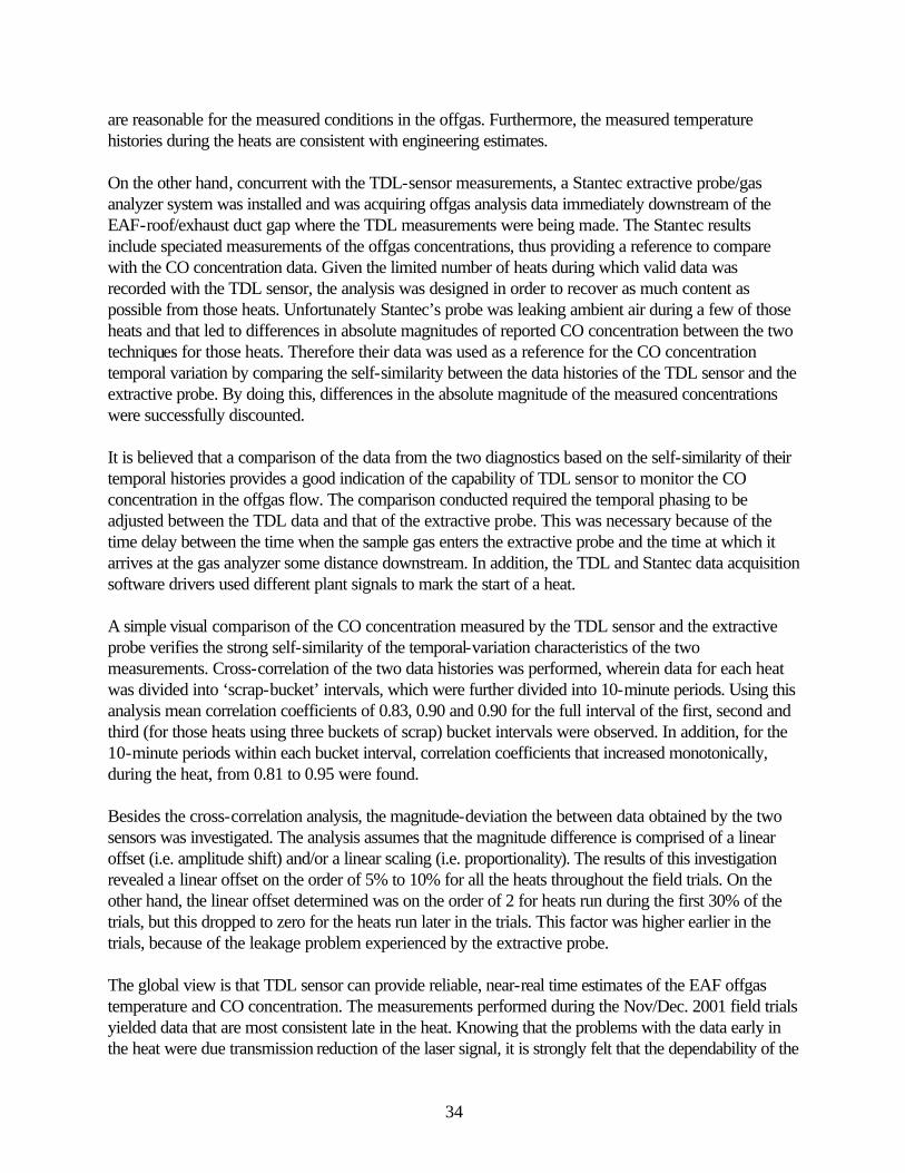
34
are reasonable for the measured conditions in the offgas. Furthermore, the measured temperature histories during the heats are consistent with engineering estimates. On the other hand, concurrent with the TDL-sensor measurements, a Stantec extractive probe/gas analyzer system was installed and was acquiring offgas analysis data immediately downstream of the EAF-roof/exhaust duct gap where the TDL measurements were being made. The Stantec results include speciated measurements of the offgas concentrations, thus providing a reference to compare with the CO concentration data. Given the limited number of heats during which valid data was recorded with the TDL sensor, the analysis was designed in order to recover as much content as possible from those heats. Unfortunately Stantec’s probe was leaking ambient air during a few of those heats and that led to differences in absolute magnitudes of reported CO concentration between the two techniques for those heats. Therefore their data was used as a reference for the CO concentration temporal variation by comparing the self-similarity between the data histories of the TDL sensor and the extractive probe. By doing this, differences in the absolute magnitude of the measured concentrations were successfully discounted. It is believed that a comparison of the data from the two diagnostics based on the self-similarity of their temporal histories provides a good indication of the capability of TDL sensor to monitor the CO concentration in the offgas flow. The comparison conducted required the temporal phasing to be adjusted between the TDL data and that of the extractive probe. This was necessary because of the time delay between the time when the sample gas enters the extractive probe and the time at which it arrives at the gas analyzer some distance downstream. In addition, the TDL and Stantec data acquisition software drivers used different plant signals to mark the start of a heat. A simple visual comparison of the CO concentration measured by the TDL sensor and the extractive probe verifies the strong self-similarity of the temporal-variation characteristics of the two measurements. Cross-correlation of the two data histories was performed, wherein data for each heat was divided into ‘scrap-bucket’ intervals, which were further divided into 10-minute periods. Using this analysis mean correlation coefficients of 0.83, 0.90 and 0.90 for the full interval of the first, second and third (for those heats using three buckets of scrap) bucket intervals were observed. In addition, for the 10-minute periods within each bucket interval, correlation coefficients that increased monotonically, during the heat, from 0.81 to 0.95 were found. Besides the cross-correlation analysis, the magnitude-deviation the between data obtained by the two sensors was investigated. The analysis assumes that the magnitude difference is comprised of a linear offset (i.e. amplitude shift) and/or a linear scaling (i.e. proportionality). The results of this investigation revealed a linear offset on the order of 5% to 10% for all the heats throughout the field trials. On the other hand, the linear offset determined was on the order of 2 for heats run during the first 30% of the trials, but this dropped to zero for the heats run later in the trials. This factor was higher earlier in the trials, because of the leakage problem experienced by the extractive probe. The global view is that TDL sensor can provide reliable, near-real time estimates of the EAF offgas temperature and CO concentration. The measurements performed during the Nov/Dec. 2001 field trials yielded data that are most consistent late in the heat. Knowing that the problems with the data early in the heat were due transmission reduction of the laser signal, it is strongly felt that the dependability of the
35
data acquired early in the heat can be significantly improved by using an adaptive gain control strategy for the lock-in amplifier, along with a more robust data-validation algorithm. Significantly, following the unsuccessful 2002 TDL tests, Stantec performed an analysis of the potential energy savings associated with deploying the current Sandia offgas measurement technology (reporting CO and offgas temperature throughout each melt) as well as an enhanced system (adding capability for CO2 and H2O). [Khan, 2003]. Their analysis predicts substantial energy savings will derive from the combined use of both the offgas sensor and their extractive probe in order to measure CO, CO2, H2, H2O, O2, and temperature during each melt. These results support further development of the TDL-based offgas system, in conjunction with the extractive probe and Stantec’s EFSOP analysis, in order to achieve the energy savings for the electric steelmaking community. Certainly, future work should explore the use of alternate mid-infrared lasers, for example quantum cascade lasers, as the radiation source for a laser-based offgas system for high-temperature, particle-laden flows such as found in commercial steelmaking.

36
7. Appendices (Proprietary)
8. Acknowledgments We specifically wish to acknowledge the critical support of our industrial partner, The Timken Company. In addition, the strong program management of the American Iron and Steel Institute’s Advance Process Control Program helped keep us focused on industry needs. Finally, it has been a pleasure to work with many talented individuals over the course of this project. In particular, the critical (and occasionally heroic) Gary Hubbard (Hubbard Associates) and Ben Chorpening (former postdoc, now at NETL) must be highlighted. We list here other major participants and thank them for their important contributions: AISI: Joe Vehec, Larry Kavanagh Process Metrix Inc.: Soren Jensen, Michel Bonin Sandia National Laboratories: Ben Chorpening, Doug Scott, Allen Salmi, Shane Sickafoose. Stantec Global Technologies, Ltd.: Howard Goodfellow, Euan Evenson, Ovidiu Negru, Marshall Khan. The Timken Company: Robert Kolarik, Tom Webb, Joe Volpe, Bill Wachsman. Sandia is a multiprogram laboratory operated by Sandia Corporation, a Lockheed Martin Company, for the United States Department of Energy’s National Nuclear Security Administration under contract DE-AC04-94AL85000.
9. References Allendorf, Sarah, Ottesen, David, and Hardesty, Donald (2002), “Optical Sensors and Controls for Improved Basic Oxygen Furnace Operations,” SAND2001-8521. AISE (1998), “The Making, Shaping and Treating of Steel, 11th Edition, Steelmaking and Refining Volume,” AISI Steel Foundation, 1998. AISI (2001), “Steel Industry Technology Roadmap,” Eds. Mark Atkinson and Robert Kolarik, American Iron and Steel Institute, 2001. Bomse, David S., Stanton, Alan C., and Silver, Joel A. (1992), “Frequency Modulation and Wavelength Modulation Spectroscopies: Comparison of Experimental Methods Using a Lead-Salt Diode Laser,” Appl. Opt. 31, 718-731 (1992). Evenson, E. (2003), Stantec Global Technologies, private communication. Farrenq, R., Guelachvili, G., Sauval, A.J., Grevesse, N., and Farmer, C.B., “Improved Dunham Coefficients for CO from Infared Solar Lines of High Rotational Excitation,” J. Molec. Spectr. 149, 375-390 (1991).

37
Khan, M. (2002), “Extractive Off-Gas Chemistry Analysis at TIMKEN using Goodfellow EFSOP : Stantec Project Report for the American Iron and Steel Institute,” November 2002. Khan, M. (2003), “TDL Sensor Technology-An Analysis of Achievable Benefits,” Stantec Project Report for The American Iron and Steel Institute, Stantec Global Technologies, January 2003. Kosterev, A.A. and Tittel, F.K., “Chemical Sensors Based on Quantum Cascade Lasers,” IEEE J. Quant. Electr. 38, 582-591 (2002). Nikkari, J.J., Di Iorio, J.M., and Thomson, M.J., (2002), “In Situ Combustion Measurements of CO, H2O, and Temperature With a 1.58-µm Diode Laser and Two-Tone Frequency Modulation,” Appl. Opt. 41 446-452 (2002). Ottesen, D.K., Hurt, R.H., and Hardesty, D.R., “Real-Time optical Diagnostics for the Basic Oxygen Steelmaking Process,” Presented at Western States Section/The Combustion institute 1992 Fall Meeting, Berkeley, CA, October 14, 1992; SAND93-8409. Ottesen, D.K., Allendorf, S.W., Hubbard, G.L., and Rosenberg, E.D., “Method and Apparatus for Off-Gas Composition Sensing,” U.S. Patent 5,984,998, Nov. 16, 1999. Sharon, 1997: “Method and Apparatus to Determine and Control the Carbon Content of Steel in a BOF Vessel,” U.S. Patent 5,603,746, Feb. 18, 1997. Pierluissi, J.H., Vanderwood, P.C., and Gomez, R.B., “Fast Calculational Algorithm for the Voigt Profile,” J. Quant. Spectrosc. Radiat. Transfer 18, 555-558 (1977). Sharon, A., “Light Sensors for BOF Carbon Control in Low Carbon Heat,” Proc. 81st Steelmaking Conference of the ISS 1998, 337. Stelts, Phillip, 1994, Private Communication, Bethlehem Steel Corporation.

38
10. Specified Distribution American Iron and Steel Institute Mr. Joseph Vehec (2 copies) 680 Andersen Drive Pittsburgh, PA 15220-2700 The Timken Company Dr. Robert V. Kolarik (3 copies) Mail Code GNW-07 1835 Dueber Avenue P.O. Box 6932 Canton, OH 44706-0932 Process Metrix, Inc. (2 copies) Dr. Michel Bonin 2110 Omega Road, Suite D San Ramon, CA 94583-1295 Stantec Global Technologies (3 copies) Dr. Howard Goodfellow Mr. Euan Evenson 170-7070 Mississauga Road Mississauga, Ontario L5N 7G2 Canada Dr. Robert Green 30 Los Alamos Court Alamo, California 94507 Dr. David Ottesen 210 Salida Del Sol Arroyo Grande, CA 93420
MS 9054 W. McLean, 8300 MS 9054 D. Hardesty, 8360 (2 copies) MS 9054 R. Carling, 8350 MS 9055 S. Allendorf, 8353 (2 copies) MS 9052 A. Salmi, 8361 MS 9052 C. Shaddix, 8361 MS 9053 G. Hubbard, 8362 MS 9404 J. Wang, 8723 MS 9403 S. Sickafoose, 8723 MS 9018 Central Technical Files, 8945-1 MS 0899 Technical Library, 9616

39
MS 9021 Classification Office, 8511/Technical Library, MS 0899, 9616
40
11. Industry Perspective The comments contained in this section of the report reflect the viewpoints of The Timken Company who hosted all of the field trials of the electric arc furnace off-gas sensor. The intent of this section is to provide the reader with an industry perspective as to the benefits and concerns of this project as well as some thoughts on the state of the technology and how it may benefit the industry in the future.
11.1 History The Steel Industry Roadmap has identified reliable monitoring of off-gas chemistry as an important step forward for energy conservation and process control in high intensity EAF steel making. Often only 50% of energy input to the EAF effectively goes into melting the scrap and heating the bath. In addition, energy losses to the off-gas system are increasing as more chemical energy is used. As a result, the steel making process and the operation of the off-gas system are becoming increasingly interrelated. It is becoming increasingly important to adopt a holistic approach to process optimization and control. Being able to control the process based on off-gas chemistry is critical to minimize these energy losses. Continuous off-gas measurement is a necessity as the chemistry of the off-gas can change dramatically on a heat-to-heat basis. The EAF Off-gas Sensor project was undertaken by a consortium of electric arc furnace steel makers as a collaborative project under the American Iron and Steel Institute’s Technology Roadmap Program (Project #9851). The TRP projects were co-funded by the U.S. Department of Energy under Award #DE-FC36-97ID13554. The EAF project was a logical follow-on to the AISI’s Advanced Process Control program, which included a project to develop laser-based spectroscopy for the basic oxygen furnace. The BOF project proved that the technology was capable of signaling the impending endpoint of the carbon blow in the BOF process. While the tunable diode laser (TDL) sensor did well in determining the state of the carbon reaction, it did not meet the predictability hoped for in determining bath temperature. Technology representatives at Timken urged the AISI to continue the BOF project turning to the EAF application. Optimization of the chemical inputs in EAF steel making holds the potential for great energy savings. The benefits were estimated to be $0.32 per ton derived from a replacement of more expensive electrical energy with less expensive chemical energy (added oxygen) and from a potential reduction in heat times. The expectation was that the project would prove the applicability of the technology in an EAF environment where the sensor would likely be in a more vulnerable location than at the top of a BOF and in a more turbulent, particulate-laden environment. In addition to CO and CO2, the H2O and temperature would be required to determine the completeness of combustion. The hope was that a sensor would be developed that could supply complete combustion information to a process control

41
system which would support efforts to improve the performance of the EAF. The steel maker could use the control system to meet current needs whether operating for efficiency, productivity or economy. The BOF project’s principal investigators from Sandia National Laboratory prepared a proposal outlining the development of an optical sensor to measure CO and CO2. After nearly a year delay, sufficient steel companies (Timken, Georgetown Steel, IPSCO and North Star Steel) were found to support the project. Goodfellow Technologies Inc. (now a part of Stantec Global Technologies Ltd) was added as a project partner. The Stantec interest was to determine if an optical sensor could replace the extractive sampling as the input to their EFSOPTM process control software. By operating the optical sensor in parallel during the project, the accuracy relative to the extractive method could be evaluated and the capability of the control software could be assessed.
11.2 Introduction The past few years have presented difficult economic conditions to domestic steel makers. Energy costs and raw material costs have risen dramatically. The challenges with rising energy costs alone have caused many steel companies to take a hard look at energy efficiencies and what can be done to improve them. As evidenced by The Timken Company’s involvement and willingness to host the field trials, Timken is committed to reducing cost through energy efficiency and is willing to apply advanced technologies, such as the TDL sensor. All of the field trials took place at the Timken’s Faircrest Steel Plant. Faircrest produces a wide range of quality alloy steel bars ranging in size from 5 to 12-inch squares and 5 to 12-inch rounds from bottom-poured ingots. Scrap is melted in a 170 ton Krupp designed EAF with a submerged tap hole, 120 MVA transformer and a direct evacuation system. The Faircrest EAF utilizes four oxy-fuel burners, two oxygen lances and carbon injection capabilities to aid in the melting process. Timken entered into this project with the intent to obtain a useable TDL sensor in which to accurately measure off-gas chemistry. The hope was to use this information along with the expertise of Stantec to help improve the chemical energy efficiency of the EAF. Steel making management directed that the process control system not be allowed to control the EAF. The skepticism was based on the lack of maturity of the control algorithm and the lack of inclusion of other important operating conditions, such as slag condition. The decision was made to use the system to support the operator’s decision making. In addition, Timken’s management agreed to practice oxygen addition for post combustion only on a limited basis, siting risks or over-temperature in the ductwork and concerns over reduced yield because of oxidation of the bath.
11.3 Results

42
As previously mentioned the TDL successfully provided CO and temperature data. These data alone did not provide a complete picture of the chemical energy utilization, but they did provide useful insight about how brief periods of incomplete combustion could be minimized. Prior to the August 2002 field trial, the TDL sensor system was not capable of providing meaningful real time data directly back to the EAF operators for process improvement. Therefore, no attempt was made to utilize the data while it was being collected. Sadly, when a program was developed that made this information readily available to the operators, the TDL sensor no longer worked properly. As noted elsewhere in this report, some difficulty was encountered in obtaining useful data at the beginning of a heat or whenever the furnace was recharged with scrap. During these time periods, the upper part of the EAF is filled with cold scrap. This is an optimal time to drive various exothermic reactions, such as CO to CO2, to completion, as complete combustion can provide additional energy for melting scrap. Comprised of relatively “delicate” technology, installing and maintaining a TDL sensor in an EAF environment proved to be a difficult task. The design of the TDL sensor system appears to have the potential to minimize daily and weekly maintenance to a point where the system could easily become part of a regular preventative maintenance plan. However, the robustness and long-viability of this equipment in such an environment remains unproven and from an industry perspective, is an area to be addressed in any for future work. A number of process changes were suggested by Stantec based on their EAF models. Plans were made to evaluate alternatives during the period when the extractive system was in place, but the TDL was unavailable. Preliminary trials indicated that projected savings may be possible. However, the decision was made to terminate the project before any definitive results could be gained from long duration trials. In the end, no changes were made to the EAF operating practices based on the sensor or control system studies. Initially, the extractive technique proved incapable of surviving the environment of the EAF exhaust system. However, through joint efforts by Timken and Stantec, the probe system was modified and demonstrated 95% availability from one maintenance period to the next.
11.4 Summary Overall, from The Timken Company’s industry perspective, the project was moderately successful. The cause of developing a new sensor was advanced and experience was gained with an expert control system. The benefits of combining the sensor and process control technologies remain apparent. A sensor was demonstrated to work in the EAF application, overcoming issues of mechanical abuse, flames and high temperature in a dusty environment and heavily particle-laden exhaust stream. The TDL data showed reasonable agreement with CO measurements by the extractive method after accounting for time lag due to the difference in measurement position. Reasonable temperature measurements

43
were also produced. While limited, the data could be used to improve the effective use of chemical energy by limiting practices that result in partial combustion of reactants. The hopes of the industry for EAF Off-gas Sensor project, i.e., delivery of a robust sensor capable of measuring all species required to assess and control combustion, were not achieved. Adequate solutions have been identified, but not implemented, to overcome the cooling and mechanical and alignment issues that plagued the TDL.
11.5 Recommendations The use of new laser technology, including quantum cascade lasers, or alternate wavelengths is a possible solution for measuring other species. The robustness of the communications and mechanical system must be achieved for survival of a rather expensive system in the steel plant. Further work is needed in those areas to deliver a sensor that the steel industry can use to advance its efforts in the area of cost reduction and energy efficiency. Stantec’s expertise in off-gas measurement and analysis experience proved valuable in better understanding the melting process. They should continue to be involved in efforts to refine the sensor to couple with their control algorithms to give the industry a better process control tool.