Embed Size (px)
Citation preview
Optical Trapping, Manipulation, and 3D Imaging ofDisclinations in Liquid Crystals and Measurementof their Line Tension
Ivan I. SmalyukhBohdan I. SenyukSergij V. ShiyanovskiiOleg D. LavrentovichThe Liquid Crystal Institute and Chemical Physics InterdisciplinaryProgram, Kent State University, Kent, Ohio
Andrey N. KuzminAlexander V. KachynskiParas N. PrasadThe Institute for Lasers, Photonics, and Biophotonics, University atBuffalo, The State University of New York, Buffalo, New York
We demonstrate optical trapping and manipulation of defects and transparentmicrospheres in nematic liquid crystals (LCs). The three-dimensional directorfields and positions of the particles are visualized using the Fluorescence ConfocalPolarizing Microscopy. We show that the disclinations of both half-integer andinteger strengths can be manipulated by either using optically trapped colloidalparticles or directly by tightly-focused laser beams. We employ this effect to mea-sure the line tensions of disclinations; the measured line tension is in a good agree-ment with theoretical predictions. The laser trapping of colloidal particles anddefects opens new possibilities for the fundamental studies of LCs.
Keywords: disclination; fluorescence confocal polarizing microscopy; laser tweezers;liquid crystal; optical manipulation
I.I.S., B.I.S., S.V.S., and O.D.L. acknowledge support of the NSF, Grant DMR-0315523. I.I.S. acknowledges the grant of the International Institute of Complex andAdaptive Matter (I2CAM) to support his participation in the 8th European Conferenceon Liquid Crystals in Sesto, Italy, and also the 2005 Fellowship of the Institute of Com-plex and Adaptive Matter. The research at Buffalo was supported by an AFOSRDURINT grant, number F496200110358. We thank Dr. L. Longa and Dr. Yu. Nastishinfor discussions.
Address correspondence to Ivan I. Smalyukh, The Liquid Crystal Institute andChemical Physics Interdisciplinary Program, Kent State University, Kent, OH 44242-0001. E-mail: [email protected]
Mol. Cryst. Liq. Cryst., Vol. 450, pp. 79=[279]–95=[295], 2006
Copyright # Taylor & Francis Group, LLC
ISSN: 1542-1406 print=1563-5287 online
DOI: 10.1080/15421400600587787
79=[279]
1. INTRODUCTION
The study of topological defects is important for understanding defect-mediated phase transitions in condensed matter [1–5]; it is also of agreat current interest in cosmology [6–9]. The nematic liquid crystals(LCs) are convenient model systems for the study of defects and can beuseful even for the ‘‘cosmology in laboratory’’ experiments [6–9]. Long-range orientational order in nematic LCs is usually described by thedirector field bnnð~rr Þ¼�bnnð~rr Þ representing the average spatial orien-tation of the LC molecules [1]. This order can be locally broken (so thatthe director field bnnð~rr Þ can not be defined) on a point, along a line, oralong a wall, giving rise to defects. The line defects in nematics arecalled disclinations; they are classified according to their strength mthat is defined as a number of revolutions by 2p that the directorbnnð~rr Þ makes around the defect core when one circumnavigates the coreonce [1]. While the half-integer defect lines are topologically stable, theinteger-strength disclinations are not and usually relax into nonsingu-lar configurations of bnnð~rr Þ. Disclinations can be obtained by a rapidquench from high-symmetry isotropic to the lower-symmetry nematicphase; it is much more difficult to spatially control (manipulate)them, a capability that would be desired for the topological studyand ‘‘cosmology-in-laboratory’’ experiments [1–9]. The field-inducedpropagation [2] and deformation [3] dynamics of disclinations allowone for a limited spatial manipulation of these defects but only atcertain boundary conditions; more robust approaches to manipulatedefects are in a great demand.
Since the pioneering experiments of Ashkin [10], the laser tweezerswere shown to be capable of trapping and manipulation of differenttransparent objects (particles) in the bulk of different isotropic media.Optical trapping became a valuable tool in physics and biology[11–15]. Laser tweezers allow one to measure pico-Newton forces asso-ciated with colloidal interactions [11] and unfolding of biopolymermolecules (by pulling a bead attached to one of the ends of the mol-ecule) [12]. Optical trapping is often described in terms of competitionof the scattering force, FScat, arising from backscattering of photonsand pushing the object along the optical axis, and the gradient force,FGrad, which pulls the object in the direction of increasing intensityof the beam, Figure 1(a) [14,15], provided that the refractive indexof the particle is larger than the refractive index of the surroundingmedium. In a laser beam tightly focused by a high numerical apertureobjective, there are substantial intensity gradients both perpendicularto the beam axis and along this axis which are pulling the beadtowards the focus with the highest laser intensity, Figure 1(a). When
80=[280] I. I. Smalyukh et al.
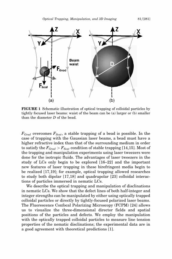
FGrad overcomes FScat, a stable trapping of a bead is possible. In thecase of trapping with the Gaussian laser beams, a bead must have ahigher refractive index than that of the surrounding medium in orderto satisfy the FGrad > FScat condition of stable trapping [14,15]. Most ofthe trapping and manipulation experiments using laser tweezers weredone for the isotropic fluids. The advantages of laser tweezers in thestudy of LCs only begin to be explored [16–22] and the importantnew features of laser trapping in these birefringent media begin tobe realized [17,19]; for example, optical trapping allowed researchesto study both dipolar [17,18] and quadrupolar [23] colloidal interac-tions of particles immersed in nematic LCs.
We describe the optical trapping and manipulation of disclinationsin nematic LCs. We show that the defect lines of both half-integer andinteger strengths can be manipulated by either using optically trappedcolloidal particles or directly by tightly-focused polarized laser beams.The Fluorescence Confocal Polarizing Microscopy (FCPM) [24] allowsus to visualize the three-dimensional director fields and spatialpositions of the particles and defects. We employ the manipulationwith the optically trapped colloidal particles to measure line tensionproperties of the nematic disclinations; the experimental data are ina good agreement with theoretical predictions [1].
FIGURE 1 Schematic illustration of optical trapping of colloidal particles bytightly focused laser beams: waist of the beam can be (a) larger or (b) smallerthan the diameter D of the bead.
Optical Trapping, Manipulation, and 3D Imaging 81=[281]
2. EXPERIMENT
2.1. Materials and Cell Preparation
We used the nematic LC mixtures ZLI2806 with small birefringenceDn�0:04 and average refractive index nLC¼
ffiffiffiffiffiffiffiffiffiffiffiffiffiffiffiffiffiffiffiffiffiffiffiffiffiffiffiffið2n2
o þ n2e Þ=3
p� 1:49
(no¼1:48 and ne¼1:52 are ordinary and extraordinary refractive indi-ces, respectively) and E7 with a comparably large birefringenceDn�0:23; nLC�1:6 (both materials were obtained from EM Chemi-cals). The LCs were doped with 0.01 wt% of fluorescent dyen,n0-bis(2,5-di-tert-butylphenyl)-3,4,9,10-perylenedicarboximide (BTBP)for the FCPM studies [24]. We used Melamine Resin (MR) sphericalparticles (purchased from Aldrich) of refractive index nMR�1:68 anddiameters D¼3mm and D¼4 mm and polystyrene (PS) microspheres(obtained from Duke Scientific) with nPS�1:6 and D¼1 mm. The MRmicrospheres were tagged with the Rhodamine B dye (maximum ofsingle-photon absorption at �540 nm) which fluoresced when excitedby the k¼568 nm Kr-laser in the FCPM experiment, and also whentrapped by k¼1064 nm laser tweezers (the later due to two-photonabsorption). Both LCs and polymer particles are transparent at thewavelength of optical trapping (k¼1064 nm), as needed to avoid heat-ing of the samples.
The cells were constructed from glass plates of small thickness(150 mm) and sealed using UV-curable glue; the cell gap was set eitherby Mylar spacers at the cell edges or using comparably big (tens ofmicrons) glass particles dispersed within the cell area. The cell gapwas varied within the range 20�100mm. Surfaces of some of the sub-strates were coated with thin polyimide layers to set the direction ofthe easy axes at the LC-glass interfaces. The LC containing small con-centration (<0.02% by weight) of well-separated polymer particles (weused sonication) was introduced into the cells by capillary forces.
We obtain disclinations of different strengths by cooling the cellsfrom the isotropic phase. The defect lines of opposite strengths quicklyannihilate with time soon after the LC is cooled below the isotropic-nematic transition. Some of the defects are trapped on spacers andirregularities or stabilized by boundary conditions at the confiningsurfaces; these disclinations will be a subject of our study.
2.2. Fluorescence Confocal Polarizing Microscopy
Using the two-channel FCPM [24], we determine the director config-urations in the cell (through the fluorescence of BTBP detected in thespectral range 510–550 nm, channel #1) as well as the positionsof the MR particles (detecting fluorescence from Rhodamine B dye
82=[282] I. I. Smalyukh et al.
embedded in the spheres in the spectral range 585–650 nm, channel#2). We used Olympus Fluoview BX-50 confocal microscope, modifiedby a linear polarizer bPP that sets polarization bPPekbPP of the excitationbeam and the polarization bPPf kbPP of the detected fluorescent light. Theexcitation beams of a 488 nm Ar laser and a 568 Kr laser are focusedby a high NA objective into a small (<1 mm3) volume in the LC cell.The fluorescent light from this volume is detected by two photomulti-plier tubes that collect light in the spectral ranges 510–550 nm forchannel #1 and 585–650 nm for channel #2 as selected by the inter-ference filters. A 100 mm wide pinhole discriminates against the regionsabove and below the selected volume, which allows for the diffraction-limited resolution along the optical axis of the microscope. The strongorientation dependence of measured fluorescence signal allows us todecipher the 3D orientation pattern from the FCPM observations.The resolution of the FCPM is �1 mm in both radial (in plane of theLC cell) and axial (along the cell normal bZZ) directions.
2.3. Laser Tweezers
We use a dual beam laser trapping system consisting of an opticalmanipulator (Solar-TII, LM-2), a TEM00 CW Nd: YAG laser (COHER-ENT, Compass 1064-2000) with k¼1064 nm, and a modified invertedmicroscope (NIKON, TE-200) [13,17]. An optical trap is formed by a100�microscope objective (NA ¼ 1.3); this trap is used for 3D position-ing of particles within the cell. The submicron waist size of the focusedlight beam (�0:8 mm) is smaller than diameters of the used polymermicrospheres, which allows us to avoid reorientation of LC moleculesunder the intense laser radiation and its influence on the results of theline tension measurements. Before each measurement, we performforce calibration in the studied sample and at the particular depth oftrapping. The focused beam is steered in the horizontal plane (planeof the cell) by a computer-controlled galvano-mirror pair; the verticalcoordinate of the trap is controlled by a piezo-stage with the accuracy0.1 mm.
3. RESULTS
3.1. Optical Trapping and Manipulation of Particlesin Liquid Crystals
Laser tweezers experiments in anisotropic fluids (such as LCs) requiresome additional care because (a) the refractive index differencebetween the particle and the host medium depends on the local LC
Optical Trapping, Manipulation, and 3D Imaging 83=[283]
director field bnnð~rrÞ and light polarization, (b) birefringence of LC resultsin light defocusing, and (c) the focused light beam can reorient thelocal bnnð~rrÞ as demonstrated for the nematic LC in flat slabs [20] andspherical droplets [22]. These problems are intrinsic when applyinglaser tweezers for the study of anisotropic media; they can be miti-gated by using LCs with small birefringence Dn and colloidal particleslarger than the waist of the laser beam, Figure 1(b), as we will showbelow.
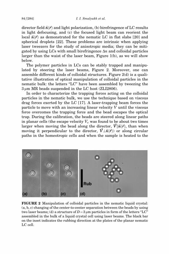
The polymer particles in LCs can be stably trapped and manipu-lated by steering the laser beams, Figure 2. Moreover, one canassemble different kinds of colloidal structures. Figure 2(d) is a quali-tative illustration of optical manipulation of colloidal particles in thenematic bulk: the letters ‘‘LC’’ have been assembled by tweezing the3mm MR beads suspended in the LC host (ZLI2806).
In order to characterize the trapping forces acting on the colloidalparticles in the nematic bulk, we use the technique based on viscousdrag forces exerted by the LC [17]. A laser-trapping beam forces theparticle to move with an increasing linear velocity V until the viscousforce overcomes the trapping force and the bead escapes the opticaltrap. During the calibration, the beads are steered along linear pathsin planar cells (the escape velocity Ve was found to be about two timeslarger when moving the bead along the director, ~VVkbnnð~rrÞ, than whenmoving it perpendicular to the director, ~VV?bnnð~rrÞ) or along circularpaths in the homeotropic cells and when the sample is heated to the
FIGURE 2 Manipulation of colloidal particles in the nematic liquid crystal:(a, b, c) changing of the center-to-center separation between the beads by usingtwo laser beams; (d) a structure of D¼3mm particles in form of the letters ‘‘LC’’assembled in the bulk of a liquid crystal cell using laser beams. The black baron the inset indicates the rubbing direction at the plates of the planar nematicLC cell.
84=[284] I. I. Smalyukh et al.
isotropic phase. The trapping force Ft is calculated using the Stoke’slaw Ft¼3pDa4Ve, where Ve is average escape velocity, and the effec-tive viscosity of the LC is approximated by the Leslie coefficient a4
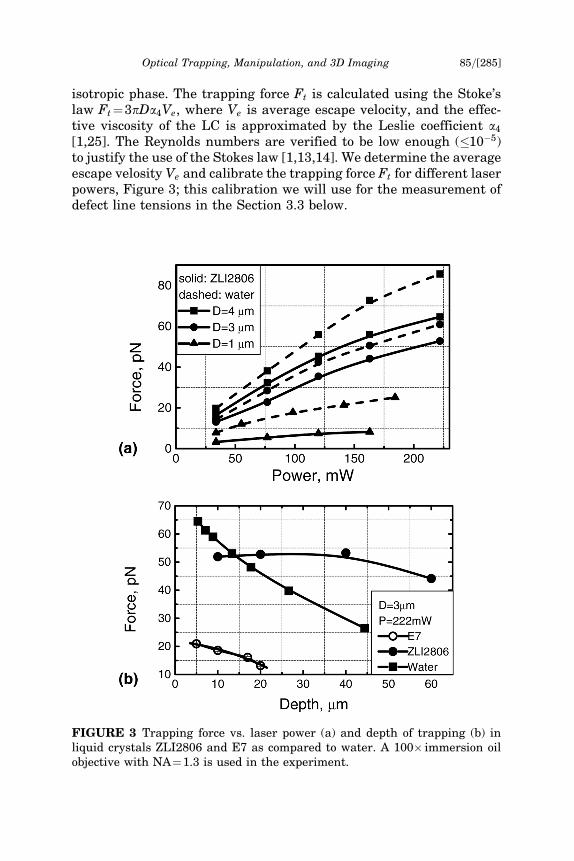
[1,25]. The Reynolds numbers are verified to be low enough (�10�5)to justify the use of the Stokes law [1,13,14]. We determine the averageescape velosity Ve and calibrate the trapping force Ft for different laserpowers, Figure 3; this calibration we will use for the measurement ofdefect line tensions in the Section 3.3 below.
FIGURE 3 Trapping force vs. laser power (a) and depth of trapping (b) inliquid crystals ZLI2806 and E7 as compared to water. A 100� immersion oilobjective with NA¼1.3 is used in the experiment.
Optical Trapping, Manipulation, and 3D Imaging 85=[285]
Similarly to the case of isotropic fluids, the optical trapping forces inLCs increase with the laser power, Figure 3(a). These forces inZLI2806 are weaker than for the same particles dispersed in water(which is natural as the difference between the refractive index ofthe particle and the surrounding medium is larger in the case ofwater) but still sufficiently strong to enable laser manipulation. Thespherical aberrations that often arise due to the refractive index mis-match at the coverslip-sample interfaces can considerably weaken thetrapping forces, especially if one uses the oil immersion objectives fortrapping in the low-refractive-index fluids such as water [15]. Becauseof the spherical aberrations, the spatial size of the focused light spotincreases with the depth of trapping and the originally sharp intensitydistribution is blurred. The spherical aberration effect on the trappingin the LC is small as the average refractive index of LCs is close to thatof a silica glass, �1:5. The efficiency of trapping in ZLI2806 with asmall birefringence Dn does not decrease much when the depth ofscanning increases, contrary to the case of water, Figure 3(b). The par-ticles suspended in ZLI2806 could be trapped even at a depth of 80 mm.However, if Dn is significant, as in the case of E7 with high birefrin-gence Dn�0:23, then substantial light defocusing weakens the trap-ping forces, Figure 3(b). When the trapping depth reaches about20 mm, optical manipulation in E7 becomes practically impossible,Figure 3(b). This result is natural, as in the birefringent media lightdefocusing (and the spatial dimensions of the optical trap) increaseswith the depth of focusing and with birefringence Dnj j of the LC [24].
The trapping forces can also depend on the director field along thepath of light if the beads are manipulated in the E7 cells; practically nosuch dependence is observed if the host medium is ZLI2806 with smallbirefringence. In general, high Dn makes quantitative measurement ofcolloidal interaction in the LC such as E7 very difficult even thoughtrapping and manipulation of beads in these media is often still poss-ible (if the depth of trapping is not too large). However, low Dn materi-als such as ZLI2806 are perfectly suited for optical trapping and can beeven used to study colloidal interactions and parameters of topologicaldefects in the nematic phase, as we demonstrate below.
3.2. 3D Imaging, Trapping, and Manipulation of Defectsin Liquid Crystals
Nematic disclinations of opposite charges have similar appearanceunder a microscope and, especially if they are parallel to the planeof observations, it is often difficult to distinguish the m¼�1=2 fromm¼1=2 as well as the m¼�1 from m¼1 defect lines. We use the
86=[286] I. I. Smalyukh et al.
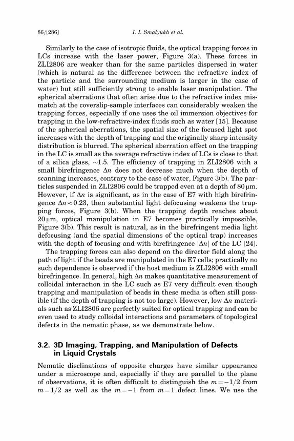
FIGURE 4 Vertical FCPM cross-sections with the fluorescent signal from(a) BTBP-doped LC and (b) Rhodamine B labeled particle (gray) and (c) sche-matic drawing of the director field with the bead in the vicinity of a disclina-tion. The color-coded FCPM fluorescence intensity scale is shown in (d). Thepolarization of the FCPM probing light is marked by ‘‘P’’ and a white bar in(a). The BTBP dye in the LC was excited with a 488 nm Ar-laser and the flu-orescent light was detected in the spectral region 510–550 nm; the RhodamineB dye incorporated in MR microspheres was excited using the 568 nm Kr-laserand the respective fluorescence signal was detected in the spectral range
Optical Trapping, Manipulation, and 3D Imaging 87=[287]
585–650 nm.
FCPM technique to map the 3D director around the disclination whichallows us to determine the strengths of defect lines. Imaging of thedirector field associated with disclination is illustrated on the exampleof a straight disclination with its ends pinned at two spacers that wereused to set the cell thickness, Figure 4. FCPM vertical cross-sectionobtained with linearly polarized probing light, Figure 4(a), revealsthe director reorientation by p around the disclination as one circum-navigates the core once, Figure 4(a). This director configuration isassisted by the type of anchoring in the cell, which was tangentialdegenerate at the top plate and homeotropic at the bottom plate. Asit is revealed by the two-channel FCPM imaging, both the disclinationand the colloidal particle that can be used to manipulate the defect lineare located in the nematic bulk, Figure 4(a–c). The co-localization ofthe fluorescent signals from the dye-doped LC (Fig. 4a, representedusing a color-coded intensity scale) and the Rhodamine B stainedMR particle (Fig. 4b) shows that the particle is located in the closevicinity of the defect core, Figure 4(c). The defect lines studied below,Figures 5–8, look similar under the polarizing microscope; the visibledifference which is usually used to distinguish them is that thehalf-integer disclinations, Figures 7 and 8 are thinner than theinteger-strength disclinations, Figures 5 and 6 (compare the thicknessof the defect lines to the diameter of the 3mm beads). Using the FCPMtechnique and mapping bnnð~rrÞ around a defect as described above, wedetermined not only the absolute value of the disclination strengthm but also its sign (the strengths of disclinations are marked inFigures 5–8).
The strong director distortions and the associated gradients of theeffective refractive index in the vicinity of the disclination cores allowfor trapping and manipulation of these defects using laser tweezers.To illustrate this we use a straight horizontal m¼1 disclination thatjoins two glass spacers in a flat cell, Figure 5. The disclination canbe stretched by manipulating the laser beam focused at the disclina-tion midway between the spacers, Figure 5. The local directorbnnð~rrÞ in the center of the m¼1 disclination is along the defect line,Figure 5(d), (e), making the defect core non-singular, i.e., escaped intothe 3rd dimension. For a laser beam polarized along the disclination,the effective refractive index in the center of the defect line isneff ;core�ne, which is larger than the effective refractive index of the sur-rounding LC�no (here no¼1:48 and ne¼1:52 are ordinary and extra-ordinary refractive indices of the used ZLI2806, respectively). Therefractive index difference between the core of the m¼1 disclinationand the LC around it is close to LC birefringence, Dn�0:04, and is suf-ficient for manipulation of the disclination using laser tweezers, Figure 5.
88=[288] I. I. Smalyukh et al.

As one can expect, the disclination is trapped when the laser beam ispolarized along the defect line, Figure 5; the defect is repelled from thefocused laser spot if the laser beam is polarized orthogonally to thedisclination as in this case the effective refractive index differencebetween the defect core and surrounding LC becomes negative. In asimilar way, the effective refractive index difference between thedefect core and surrounding LC allows one to optically trap andmanipulate other types of disclinations using tightly focused laserbeams. We note that in addition to the mechanism of disclination trap-ping described above, the trapping and manipulation of disclinationsmight be also influenced by the LC realignment under the intenselaser radiation. If laser power exceeds some critical value (about30–50 mW in the case of ZLI2806) and the direction of linear lightpolarization differs from the local director bnnð~rrÞ, we notice spots ofrealigned LC at the place of focused infrared laser beam, similar to
FIGURE 5 Trapping and manipulation of a m ¼ 1 disclination that has anonsingular core escaped into the 3rd dimension: (a, b, c) polarizing micro-scopy images of the disclination manipulated by the infrared (the laser spotis not visible on the images) laser beam and (d, e) schematic illustration ofthe director field in the vicinity of the disclination and its trapping by afocused laser beam.
Optical Trapping, Manipulation, and 3D Imaging 89=[289]
those observed in Ref. [19]. The effect of light-induced LC realignmenton the manipulation of disclinations increases with laser power.Because of the nonlinear optical effects such as LC reorientation atlaser irradiation, quantitative characterization of laser trapping ofdisclinations with high-power laser tweezers is difficult.
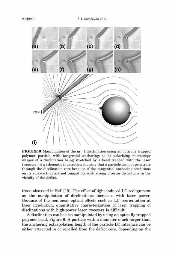
A disclination can be also manipulated by using an optically trappedpolymer bead, Figure 6. A particle with a diameter much larger thanthe anchoring extrapolation length of the particle-LC interface can beeither attracted to or repelled from the defect core, depending on the
FIGURE 6 Manipulation of the m¼1 disclination using an optically trappedpolymer particle with tangential anchoring: (a–h) polarizing microscopyimages of a disclination being stretched by a bead trapped with the lasertweezers; (i) a schematic illustration showing that a particle can not penetratethrough the disclination core because of the tangential anchoring conditionson its surface that are not compatible with strong director distortions in thevicinity of the defect.
90=[290] I. I. Smalyukh et al.
type of disclination and surface anchoring conditions at the particle’ssurface. For example, pulling the MR spherical particle with thetangential anchoring conditions into the defect core of the m¼1disclination with a nonsingular defect core would require strong
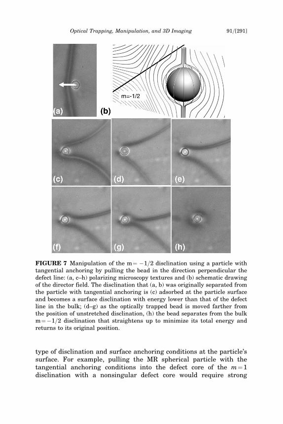
FIGURE 7 Manipulation of the m¼ �1=2 disclination using a particle withtangential anchoring by pulling the bead in the direction perpendicular thedefect line: (a, c–h) polarizing microscopy textures and (b) schematic drawingof the director field. The disclination that (a, b) was originally separated fromthe particle with tangential anchoring is (c) adsorbed at the particle surfaceand becomes a surface disclination with energy lower than that of the defectline in the bulk; (d–g) as the optically trapped bead is moved farther fromthe position of unstretched disclination, (h) the bead separates from the bulkm¼�1=2 disclination that straightens up to minimize its total energy andreturns to its original position.
Optical Trapping, Manipulation, and 3D Imaging 91=[291]
director transformation, Figure 6(i); this is associated with an ener-getic barrier and explains why the optically trapped bead can not easilypenetrate through the m¼1 defect line. One might wonder why thedisclination does not leave the particle and passes over the top=bottombottom of the bead. The most plausible reason is pinning at the surface.Similar effect of pinning of disclination ends has been demonstrated inthe experiments of Ref. [5] in which the disclinations joined two platesthat were rotated with respect to each other. Despite the fact that thealignment at the plates was tangentially degenerate, the ends movedwith the plates (thus stretching the disclinations themselves) demon-strating the effect of pinning [5]. By manipulating a particle, the discli-nation with its ends pinned at glass spacers can be stretched similarlyto the case of an elastic string, Figure 5. When laser light is switchedoff, the disclination straightens up and pushes the bead. This is naturalas the energy of a straight disclination is proportional to its length and,in first approximation, also the energy of the curved defect line isproportional to its length [1]. Therefore, a curved defect line has atendency to straighten, in order to decrease its length and total elasticenergy. This tendency can be described in the terms of a line tension,defined as a ratio of the variation of elastic energy to the variation inlength [1], which will be studied in Section 3.3.
An optically trapped MR particle also allows us to manipulate ahalf-integer m¼�1=2 disclination, Figure 7. The bulk half-integer dis-clination has a singular core of the size rc close to the molecular size(or somewhat larger), of the order of (1–10) nm for a typical nematicthermotropic material such as E7 and ZLI2806, see also [27]. The sur-face disclination can have a much wider core, of the order of the ratio
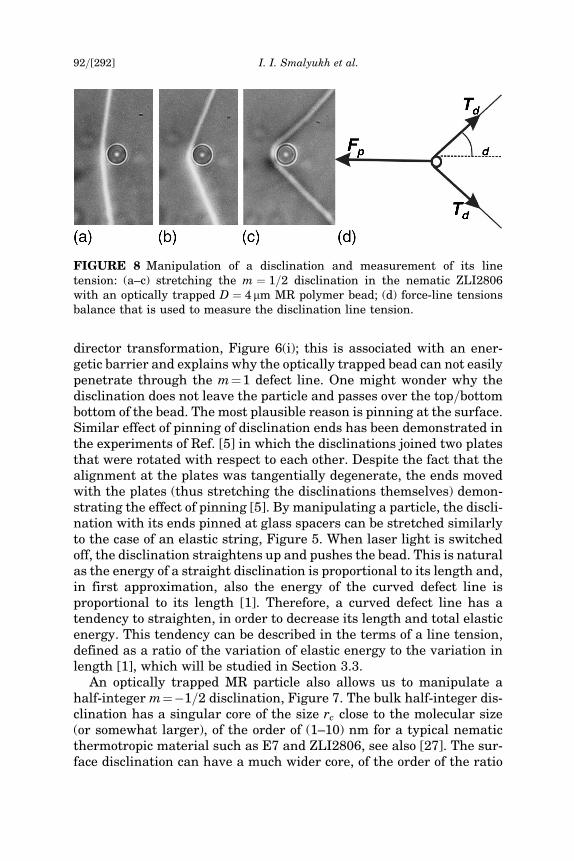
FIGURE 8 Manipulation of a disclination and measurement of its linetension: (a–c) stretching the m ¼ 1=2 disclination in the nematic ZLI2806with an optically trapped D ¼ 4 mm MR polymer bead; (d) force-line tensionsbalance that is used to measure the disclination line tension.
92=[292] I. I. Smalyukh et al.
of the bulk elastic constant K and the surface anchoring coefficientW; l ¼ K=W, which is normally in the range 0:1�1 mm [1,28]. Theenergy of the disclination at the surface of the particle can be lowerthan the energy of a disclination in the bulk, as discussed by R. B.Meyer [28]. The disclination located sufficiently close to the surfaceof a particle might transform into the surface disclination, i.e., intothe line which core is located at the surface and is thus of the sizel >> rc. In the end of this manipulation process the particle andm¼�1=2 disclination separate; the defect line quickly straightensup and returns to its original location.
3.3. Measurements of the Disclination Line Tension
Since the elastic constants in most nematics are �10 pN, the opticaltrapping approach [17] is also well suited for the quantitative studyof line tension of defects. This we demonstrate below on an exampleof a m¼1=2 disclination. Neglecting the difference in the values ofFrank elastic constants, the line tension of the topologically-stablehalf-integer disclination is approximated as [1]:
Td ¼p4
K lnL
rcþ Tc; ð1Þ
where K is the average elastic constant, L is the characteristic size ofthe system (sample thickness in our case), rc and Tc are the radius andenergy of the defect core. In the model of an isotropic (melted) core [1],Tc�pK=4 and rc�10 nm. With the average elastic constant for ZLI2806K�12 pN and L¼10�100 mm, Eq. (1) predicts Td¼ 65�85 pN.
By moving the particle with the laser tweezers, Figure 8(a–c), thedisclination can be pulled similarly to an elastic string. When the beadis released from the optical trap, the disclination straightens up inorder to minimize its length and thus the total elastic energy, Eq. (1).Displacing the particle by some distance and gradually decreasing thelaser power, we find the magnitude of the pulling force Fp (equal tothe optical trapping force Ft) for which Fp¼2Td � cos hd, where hd
is the angle defined in Figure 8(d). For hd in the range 90�45�, we findthe line tension of disclination Td¼74� 4 pN, close to the estimateobtained from Eq. (1) and to the data obtained by observations of ther-mal fluctuations of the defect line [29].
4. CONCLUSIONS
We demonstrated that the laser tweezers can be used to trap andmanipulate defects in the nematic phase of thermotropic liquid
Optical Trapping, Manipulation, and 3D Imaging 93=[293]
crystals. We measured the disclination line tension which is found tobe in a good agreement with the theoretical predictions. Laser trap-ping and manipulation of defects opens new possibilities for the funda-mental studies of liquid crystals as well as defects in general. Inparticular, optical manipulation and disclination line tension mea-surements might be very useful tools to study defects in biaxialnematic LCs [30–32], properties of which are much less understoodas compared to the case of uniaxial nematics.
REFERENCES
[1] Kleman, M. & Lavrentovich, O. D. (2003). Soft Matter Physics: An Introduction,Springer-Verlag: New York.
[2] Cladis, P. E., van Saarloos, W., Finn, P. L., & Kortan, R. (1987). Phys. Rev. Lett., 58,222.
[3] Vella, A., Intartaglia, R., Blanc, C., Smalyukh, I. I., Lavrentovich, O. D., & Nobili, M.(2005). Phys. Rev. E., 71, 061705.
[4] Smalyukh, I. I. & Lavrentovich, O. D. (2003). Phys. Rev. Let., 90, 085503.[5] Ishikawa, T. & Lavrentovich, O. D. (1998). Europhys. Lett., 41, 171.[6] Durrer, R., Kunz, M., & Melchiorri, A. (2002). Phys. Rep., 364, 1–81.[7] Kibble, T. W. B. (2003). In: Symmetry Breaking and Defects, Arodz, H. et al. (Eds.),
Kluwer Academic Publishers: Netherlands, Chapter 1, 3–36.[8] Chuang, I., Durrer, R., Turok, N., & Yurke, B. (1991). Science, 251, 1336.[9] Bowick, M. J., Chandar, L., Schiff, E. A., & Srivastava, A. M. (1994). Science, 263,
943.[10] Ashkin, A. (1970). Phys. Rev. Lett., 24, 156; Ashkin, A., Dziedzic, J. M., Bjorkholm,
J. E., & Chu, S. (1986). Opt. Lett., 11, 288.[11] Onoa, B., Dumont, S., Liphardt, J., Smith, S., Tinoco, I., & Bustamante, C. (2003).
Science, 229, 1892.[12] Larsen, A. E. & Grier, D. G. (1997). Nature, 385, 230.[13] Kachynski, A. V., Kuzmin, A. N., Pudavar, H. E, Kaputa, D. S., Cartwright, A. N., &
Prasad, P. N. (2003). Opt. Lett., 28, 2288.[14] Prasad, P. N. (2003). Introduction to Biophotonics, Wiley: New York.[15] Neuman, K. C. & Block, S. M. (2004). Rev. Sci. Instr., 75, 2787.[16] Ivashita, Y. & Tanaka, H. (2003). Phys. Rev. Lett., 90, 045501.[17] Smalyukh, I. I., Kuzmin, A. N., Kachynskii, A. V., Prasad, P. N., & Lavrentovich,
O. D. (2005). Appl. Phys. Lett., 86, 021913.[18] Yada, M., Yamamoto, J., & Yokoyama, H. (2004). Phys. Rev. Lett., 92, 185501.[19] Mu�ssevic, I., �sskarabot, M., Babic, D., Osterman, N., Poberaj, I., Nazarenko, V., &
Nych, A. (2004). Phys. Rev. Lett., 93, 187801.[20] Hotta, J., Sasaki, K., & Masuhara, H. (1997). Appl. Phys. Lett., 71, 2085.[21] Juodkazis, S., Matsuo, S., Murazawa, N., Hasegawa, I., & Misawa, H. (2003). Appl.
Phys. Lett., 82, 4657.[22] Wood, T., Gleeson, H. F., Dickinson, M., & Wright, A. J. (2004). Appl. Phys. Lett.,
84, 4292.[23] Smalyukh, I. I., Lavrentovich, O. D., Kuzmin, A. N., Kachynski, A. V., & Prasad,
P. N. (2005). Appl. Phys. Lett., 86, 021913.[24] Smalyukh, I. I., Shiyanovskii, S. V., & Lavrentovich, O. D. (2001). Chem. Phys.
Lett., 336, 88.
94=[294] I. I. Smalyukh et al.

[25] Poulin, Ph., Cabuil, V., & Weitz, D. A. (1997). Phys. Rev. Lett., 79, 4862.[26] Lyuksyutov, I. F. (1978). Zh. Exp. Teor. Fiz., 75, 358; Sov. Phys. JETP, 48, 178.[27] Meyer, R. B. (1973). Solid State Communications, 12, 585.[28] Mertelj, A. & Copic, M. (2004). Phys. Rev. E, 69, 021711.[29] Madsen, L. A., Dingemans, T. J., Nakata, M., & Samulski, E. T. (2004). Phys. Rev.
Lett., 92, 145505.[30] Acharya, B. R., Primak, A., & Kumar, S. (2004). Phys. Rev. Lett., 92, 145506.[31] Chiccoli, C., Feruli, I., Lavrentovich, O. D., Pasini, P., Shiyanovskii, S. V., &
Zannoni, C. (2002). Phys. Rev. E, 66, 030701.
Optical Trapping, Manipulation, and 3D Imaging 95=[295]