Embed Size (px)
Citation preview
OpticsTotal Internal Reflection
Image formation from Mirrors
Lana Sheridan
De Anza College
June 9, 2020
Last time
• refraction
• dispersion
Overview
• dispersion
• total internal reflection
• ray diagrams and terminology
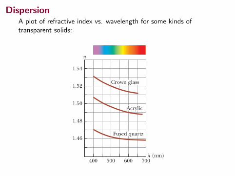
DispersionA plot of refractive index vs. wavelength for some kinds oftransparent solids:
1072 Chapter 35 The Nature of Light and the Principles of Ray Optics
same time, the wave at B emits a Huygens wavelet (the light brown circular arc passing through C) with the incident light making an angle g with the surface. Figure 35.19 shows these wavelets after a time interval Dt, after which ray 2 strikes the surface. Because both rays 1 and 2 move with the same speed, we must have AD 5 BC 5 c Dt. The remainder of our analysis depends on geometry. Notice that the two tri-angles ABC and ADC are congruent because they have the same hypotenuse AC and because AD 5 BC. Figure 35.19 shows that
cos g 5BCAC and cos g r 5
ADAC
where g 5 90° 2 u1 and g9 5 90° 2 u91. Because AD 5 BC,
cos g 5 cos g9
Therefore,
g 5 g9
90° 2 u1 5 90° 2 u91
and
u1 5 u91
which is the law of reflection. Now let’s use Huygens’s principle to derive Snell’s law of refraction. We focus our attention on the instant ray 1 strikes the surface and the subsequent time interval until ray 2 strikes the surface as in Figure 35.20. During this time interval, the wave at A sends out a Huygens wavelet (the light brown arc passing through D) and the light refracts into the material, making an angle u2 with the normal to the surface. In the same time interval, the wave at B sends out a Huygens wavelet (the light brown arc passing through C) and the light continues to propagate in the same direction. Because these two wavelets travel through different media, the radii of the wavelets are different. The radius of the wavelet from A is AD 5 v2 Dt, where v2 is the wave speed in the second medium. The radius of the wavelet from B is BC 5 v1 Dt, where v1 is the wave speed in the original medium. From triangles ABC and ADC, we find that
sin u1 5BCAC
5v1 DtAC
and sin u2 5ADAC
5v2 DtAC
Dividing the first equation by the second gives
sin u1
sin u25
v1
v2
From Equation 35.4, however, we know that v1 5 c/n1 and v2 5 c/n2. Therefore,
sin u1
sin u25
c/n 1
c/n 25
n 2
n1
and
n1 sin u1 5 n2 sin u2
which is Snell’s law of refraction.
35.7 DispersionAn important property of the index of refraction n is that, for a given material, the index varies with the wavelength of the light passing through the material as Figure 35.21 shows. This behavior is called dispersion. Because n is a function of wavelength, Snell’s law of refraction indicates that light of different wavelengths is refracted at different angles when incident on a material.
1.52
1.50
1.48
1.46
400 500 600 700
n
l (nm)
Acrylic
Crown glass
Fused quartz
1.54
Figure 35.21 Variation of index of refraction with vacuum wave-length for three materials.
C
B
1
2
A
D
u1
u1
u2
This wavelet was sent out by wave 1 from point A.
This wavelet was sent out at the same time by wave 2 from point B.
u2
Figure 35.20 Huygens’s con-struction for proving Snell’s law of refraction.
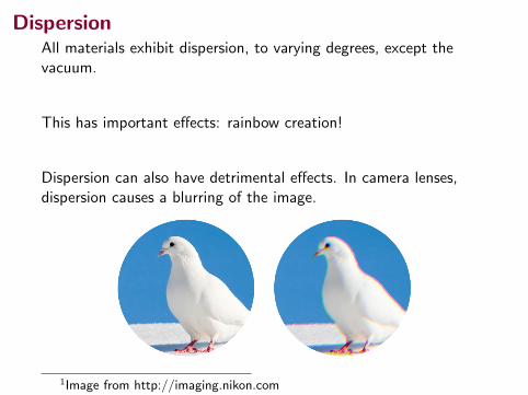
DispersionAll materials exhibit dispersion, to varying degrees, except thevacuum.
This has important effects: rainbow creation!
Dispersion can also have detrimental effects. In camera lenses,dispersion causes a blurring of the image.
1Image from http://imaging.nikon.com
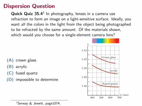
Dispersion QuestionQuick Quiz 35.41 In photography, lenses in a camera userefraction to form an image on a light-sensitive surface. Ideally, youwant all the colors in the light from the object being photographedto be refracted by the same amount. Of the materials shown,which would you choose for a single-element camera lens?
(A) crown glass
(B) acrylic
(C) fused quartz
(D) impossible to determine
1072 Chapter 35 The Nature of Light and the Principles of Ray Optics
same time, the wave at B emits a Huygens wavelet (the light brown circular arc passing through C) with the incident light making an angle g with the surface. Figure 35.19 shows these wavelets after a time interval Dt, after which ray 2 strikes the surface. Because both rays 1 and 2 move with the same speed, we must have AD 5 BC 5 c Dt. The remainder of our analysis depends on geometry. Notice that the two tri-angles ABC and ADC are congruent because they have the same hypotenuse AC and because AD 5 BC. Figure 35.19 shows that
cos g 5BCAC and cos g r 5
ADAC
where g 5 90° 2 u1 and g9 5 90° 2 u91. Because AD 5 BC,
cos g 5 cos g9
Therefore,
g 5 g9
90° 2 u1 5 90° 2 u91
and
u1 5 u91
which is the law of reflection. Now let’s use Huygens’s principle to derive Snell’s law of refraction. We focus our attention on the instant ray 1 strikes the surface and the subsequent time interval until ray 2 strikes the surface as in Figure 35.20. During this time interval, the wave at A sends out a Huygens wavelet (the light brown arc passing through D) and the light refracts into the material, making an angle u2 with the normal to the surface. In the same time interval, the wave at B sends out a Huygens wavelet (the light brown arc passing through C) and the light continues to propagate in the same direction. Because these two wavelets travel through different media, the radii of the wavelets are different. The radius of the wavelet from A is AD 5 v2 Dt, where v2 is the wave speed in the second medium. The radius of the wavelet from B is BC 5 v1 Dt, where v1 is the wave speed in the original medium. From triangles ABC and ADC, we find that
sin u1 5BCAC
5v1 DtAC
and sin u2 5ADAC
5v2 DtAC
Dividing the first equation by the second gives
sin u1
sin u25
v1
v2
From Equation 35.4, however, we know that v1 5 c/n1 and v2 5 c/n2. Therefore,
sin u1
sin u25
c/n 1
c/n 25
n 2
n1
and
n1 sin u1 5 n2 sin u2
which is Snell’s law of refraction.
35.7 DispersionAn important property of the index of refraction n is that, for a given material, the index varies with the wavelength of the light passing through the material as Figure 35.21 shows. This behavior is called dispersion. Because n is a function of wavelength, Snell’s law of refraction indicates that light of different wavelengths is refracted at different angles when incident on a material.
1.52
1.50
1.48
1.46
400 500 600 700
n
l (nm)
Acrylic
Crown glass
Fused quartz
1.54
Figure 35.21 Variation of index of refraction with vacuum wave-length for three materials.
C
B
1
2
A
D
u1
u1
u2
This wavelet was sent out by wave 1 from point A.
This wavelet was sent out at the same time by wave 2 from point B.
u2
Figure 35.20 Huygens’s con-struction for proving Snell’s law of refraction.
1Serway & Jewett, page1074.
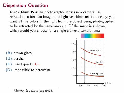
Dispersion QuestionQuick Quiz 35.41 In photography, lenses in a camera userefraction to form an image on a light-sensitive surface. Ideally, youwant all the colors in the light from the object being photographedto be refracted by the same amount. Of the materials shown,which would you choose for a single-element camera lens?
(A) crown glass
(B) acrylic
(C) fused quartz←(D) impossible to determine
1072 Chapter 35 The Nature of Light and the Principles of Ray Optics
same time, the wave at B emits a Huygens wavelet (the light brown circular arc passing through C) with the incident light making an angle g with the surface. Figure 35.19 shows these wavelets after a time interval Dt, after which ray 2 strikes the surface. Because both rays 1 and 2 move with the same speed, we must have AD 5 BC 5 c Dt. The remainder of our analysis depends on geometry. Notice that the two tri-angles ABC and ADC are congruent because they have the same hypotenuse AC and because AD 5 BC. Figure 35.19 shows that
cos g 5BCAC and cos g r 5
ADAC
where g 5 90° 2 u1 and g9 5 90° 2 u91. Because AD 5 BC,
cos g 5 cos g9
Therefore,
g 5 g9
90° 2 u1 5 90° 2 u91
and
u1 5 u91
which is the law of reflection. Now let’s use Huygens’s principle to derive Snell’s law of refraction. We focus our attention on the instant ray 1 strikes the surface and the subsequent time interval until ray 2 strikes the surface as in Figure 35.20. During this time interval, the wave at A sends out a Huygens wavelet (the light brown arc passing through D) and the light refracts into the material, making an angle u2 with the normal to the surface. In the same time interval, the wave at B sends out a Huygens wavelet (the light brown arc passing through C) and the light continues to propagate in the same direction. Because these two wavelets travel through different media, the radii of the wavelets are different. The radius of the wavelet from A is AD 5 v2 Dt, where v2 is the wave speed in the second medium. The radius of the wavelet from B is BC 5 v1 Dt, where v1 is the wave speed in the original medium. From triangles ABC and ADC, we find that
sin u1 5BCAC
5v1 DtAC
and sin u2 5ADAC
5v2 DtAC
Dividing the first equation by the second gives
sin u1
sin u25
v1
v2
From Equation 35.4, however, we know that v1 5 c/n1 and v2 5 c/n2. Therefore,
sin u1
sin u25
c/n 1
c/n 25
n 2
n1
and
n1 sin u1 5 n2 sin u2
which is Snell’s law of refraction.
35.7 DispersionAn important property of the index of refraction n is that, for a given material, the index varies with the wavelength of the light passing through the material as Figure 35.21 shows. This behavior is called dispersion. Because n is a function of wavelength, Snell’s law of refraction indicates that light of different wavelengths is refracted at different angles when incident on a material.
1.52
1.50
1.48
1.46
400 500 600 700
n
l (nm)
Acrylic
Crown glass
Fused quartz
1.54
Figure 35.21 Variation of index of refraction with vacuum wave-length for three materials.
C
B
1
2
A
D
u1
u1
u2
This wavelet was sent out by wave 1 from point A.
This wavelet was sent out at the same time by wave 2 from point B.
u2
Figure 35.20 Huygens’s con-struction for proving Snell’s law of refraction.
1Serway & Jewett, page1074.
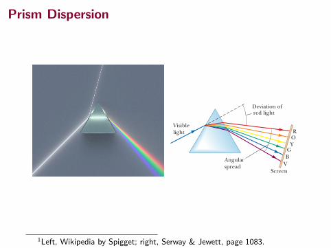
Prism Dispersion
Problems 1083
the middle of the container’s bottom as shown in Fig-ure P35.32b. (a) Show that the ratio h/d is given by
hd
5 Ån2 2 14 2 n2
(b) Assuming the container has a width of 8.00 cm and is filled with water, use the expression above to find the height of the container. (c) For what range of val-ues of n will the center of the coin not be visible for any values of h and d?
33. A laser beam is incident on a 45°–45°–90° prism perpendicular to one of its faces as shown in Fig-ure P35.33. The trans-mitted beam that exits the hypotenuse of the prism makes an angle of u 5 15.0° with the direc-tion of the incident beam. Find the index of refraction of the prism.
34. A submarine is 300 m horizontally from the shore of a freshwater lake and 100 m beneath the surface of the water. A laser beam is sent from the submarine so that the beam strikes the surface of the water 210 m from the shore. A building stands on the shore, and the laser beam hits a target at the top of the building. The goal is to find the height of the target above sea level. (a) Draw a diagram of the situation, identifying the two triangles that are important in finding the solution. (b) Find the angle of incidence of the beam striking the water–air interface. (c) Find the angle of refraction. (d) What angle does the refracted beam make with the horizontal? (e) Find the height of the target above sea level.
35. A beam of light both reflects and refracts at the surface between air and glass as shown in Figure P35.35. If the refractive index of the glass is ng , find the angle of incidence u1 in the air that would result in the reflected ray and the refracted ray being per-pendicular to each other.
Section 35.6 Huygens’s PrincipleSection 35.7 Dispersion 36. The index of refraction for red light in water is 1.331
and that for blue light is 1.340. If a ray of white light enters the water at an angle of incidence of 83.0°, what are the underwater angles of refraction for the (a) red and (b) blue components of the light?
37. A light beam containing red and violet wavelengths is incident on a slab of quartz at an angle of incidence of 50.0°. The index of refraction of quartz is 1.455 at 600 nm (red light), and its index of refraction is 1.468 at 410 nm (violet light). Find the dispersion of the slab, which is defined as the difference in the angles of refraction for the two wavelengths.
45.0°
u
Figure P35.33
GP
ng
1θ
Figure P35.35
S
38. The speed of a water wave is described by v 5 !gd , where d is the water depth, assumed to be small com-pared to the wavelength. Because their speed changes, water waves refract when moving into a region of dif-ferent depth. (a) Sketch a map of an ocean beach on the eastern side of a landmass. Show contour lines of constant depth under water, assuming a reasonably uniform slope. (b) Suppose waves approach the coast from a storm far away to the north–northeast. Dem-onstrate that the waves move nearly perpendicular to the shoreline when they reach the beach. (c) Sketch a map of a coastline with alternating bays and headlands as suggested in Figure P35.38. Again make a reason-able guess about the shape of contour lines of constant depth. (d) Suppose waves approach the coast, carrying energy with uniform density along originally straight wave fronts. Show that the energy reaching the coast is concentrated at the headlands and has lower intensity in the bays.
Figure P35.38
Andy
Rya
n/St
one/
Gett
y Im
ages
39. The index of refraction for violet light in silica flint glass is 1.66, and that for red light is 1.62. What is the angular spread of visible light passing through a prism of apex angle 60.0° if the angle of incidence is 50.0°? See Figure P35.39.
Visible light
Angular spread
Deviation ofred light
Screen
ROY
GB
V
Figure P35.39 Problems 39 and 40.
40. The index of refraction for violet light in silica flint glass is nV , and that for red light is nR. What is the angular spread of visible light passing through a prism of apex angle F if the angle of incidence is u? See Figure P35.39.
Section 35.8 Total Internal Reflection 41. A glass optical fiber (n 5 1.50) is submerged in water
(n 5 1.33). What is the critical angle for light to stay inside the fiber?
M
S
1Left, Wikipedia by Spigget; right, Serway & Jewett, page 1083.
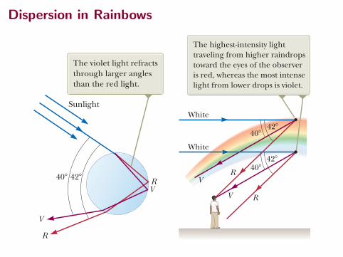
Dispersion in Rainbows 35.7 Dispersion 1073
Figure 35.21 shows that the index of refraction generally decreases with increas-ing wavelength. For example, violet light refracts more than red light does when passing into a material. Now suppose a beam of white light (a combination of all visible wavelengths) is incident on a prism as illustrated in Figure 35.22. Clearly, the angle of deviation d depends on wavelength. The rays that emerge spread out in a series of colors known as the visible spectrum. These colors, in order of decreasing wavelength, are red, orange, yellow, green, blue, and violet. Newton showed that each color has a particular angle of deviation and that the colors can be recombined to form the original white light. The dispersion of light into a spectrum is demonstrated most vividly in nature by the formation of a rainbow, which is often seen by an observer positioned between the Sun and a rain shower. To understand how a rainbow is formed, consider Fig-ure 35.23. We will need to apply both the wave under reflection and wave under refraction models. A ray of sunlight (which is white light) passing overhead strikes a drop of water in the atmosphere and is refracted and reflected as follows. It is first refracted at the front surface of the drop, with the violet light deviating the most and the red light the least. At the back surface of the drop, the light is reflected and returns to the front surface, where it again undergoes refraction as it moves from water into air. The rays leave the drop such that the angle between the incident white light and the most intense returning violet ray is 40° and the angle between the incident white light and the most intense returning red ray is 42°. This small angular difference between the returning rays causes us to see a colored bow. Now suppose an observer is viewing a rainbow as shown in Figure 35.24. If a rain-drop high in the sky is being observed, the most intense red light returning from the drop reaches the observer because it is deviated the least; the most intense vio-let light, however, passes over the observer because it is deviated the most. Hence, the observer sees red light coming from this drop. Similarly, a drop lower in the sky directs the most intense violet light toward the observer and appears violet to the observer. (The most intense red light from this drop passes below the observer’s eye and is not seen.) The most intense light from other colors of the spectrum reaches the observer from raindrops lying between these two extreme positions. Figure 35.25 (page 1074) shows a double rainbow. The secondary rainbow is fainter than the primary rainbow, and the colors are reversed. The secondary rainbow arises from light that makes two reflections from the interior surface before exiting
The colors in the refracted beam are separated because dispersion in the prism causes different wavelengths of light to be refracted through different angles.
Figure 35.22 White light enters a glass prism at the upper left.
Davi
d Pa
rker
/Sci
ence
Pho
to L
ibra
ry/P
hoto
Res
earc
hers
, Inc
.
The violet light refracts through larger angles than the red light.
Sunlight
40! 42!
V
R
RV
Figure 35.23 Path of sunlight through a spherical raindrop. Light following this path contrib-utes to the visible rainbow.
Pitfall Prevention 35.5A Rainbow of Many Light Rays Pictorial representations such as Figure 35.23 are subject to misin-terpretation. The figure shows one ray of light entering the raindrop and undergoing reflection and refraction, exiting the raindrop in a range of 40° to 42° from the entering ray. This illustration might be interpreted incorrectly as meaning that all light entering the raindrop exits in this small range of angles. In reality, light exits the raindrop over a much larger range of angles, from 0° to 42°. A care-ful analysis of the reflection and refraction from the spherical rain-drop shows that the range of 40° to 42° is where the highest-intensity light exits the raindrop.
White
42!40!
42!40!
White
The highest-intensity light traveling from higher raindrops toward the eyes of the observer is red, whereas the most intense light from lower drops is violet.
R
R
V
V
Figure 35.24 The formation of a rainbow seen by an observer stand-ing with the Sun behind his back.
35.7 Dispersion 1073
Figure 35.21 shows that the index of refraction generally decreases with increas-ing wavelength. For example, violet light refracts more than red light does when passing into a material. Now suppose a beam of white light (a combination of all visible wavelengths) is incident on a prism as illustrated in Figure 35.22. Clearly, the angle of deviation d depends on wavelength. The rays that emerge spread out in a series of colors known as the visible spectrum. These colors, in order of decreasing wavelength, are red, orange, yellow, green, blue, and violet. Newton showed that each color has a particular angle of deviation and that the colors can be recombined to form the original white light. The dispersion of light into a spectrum is demonstrated most vividly in nature by the formation of a rainbow, which is often seen by an observer positioned between the Sun and a rain shower. To understand how a rainbow is formed, consider Fig-ure 35.23. We will need to apply both the wave under reflection and wave under refraction models. A ray of sunlight (which is white light) passing overhead strikes a drop of water in the atmosphere and is refracted and reflected as follows. It is first refracted at the front surface of the drop, with the violet light deviating the most and the red light the least. At the back surface of the drop, the light is reflected and returns to the front surface, where it again undergoes refraction as it moves from water into air. The rays leave the drop such that the angle between the incident white light and the most intense returning violet ray is 40° and the angle between the incident white light and the most intense returning red ray is 42°. This small angular difference between the returning rays causes us to see a colored bow. Now suppose an observer is viewing a rainbow as shown in Figure 35.24. If a rain-drop high in the sky is being observed, the most intense red light returning from the drop reaches the observer because it is deviated the least; the most intense vio-let light, however, passes over the observer because it is deviated the most. Hence, the observer sees red light coming from this drop. Similarly, a drop lower in the sky directs the most intense violet light toward the observer and appears violet to the observer. (The most intense red light from this drop passes below the observer’s eye and is not seen.) The most intense light from other colors of the spectrum reaches the observer from raindrops lying between these two extreme positions. Figure 35.25 (page 1074) shows a double rainbow. The secondary rainbow is fainter than the primary rainbow, and the colors are reversed. The secondary rainbow arises from light that makes two reflections from the interior surface before exiting
The colors in the refracted beam are separated because dispersion in the prism causes different wavelengths of light to be refracted through different angles.
Figure 35.22 White light enters a glass prism at the upper left.
Davi
d Pa
rker
/Sci
ence
Pho
to L
ibra
ry/P
hoto
Res
earc
hers
, Inc
.
The violet light refracts through larger angles than the red light.
Sunlight
40! 42!
V
R
RV
Figure 35.23 Path of sunlight through a spherical raindrop. Light following this path contrib-utes to the visible rainbow.
Pitfall Prevention 35.5A Rainbow of Many Light Rays Pictorial representations such as Figure 35.23 are subject to misin-terpretation. The figure shows one ray of light entering the raindrop and undergoing reflection and refraction, exiting the raindrop in a range of 40° to 42° from the entering ray. This illustration might be interpreted incorrectly as meaning that all light entering the raindrop exits in this small range of angles. In reality, light exits the raindrop over a much larger range of angles, from 0° to 42°. A care-ful analysis of the reflection and refraction from the spherical rain-drop shows that the range of 40° to 42° is where the highest-intensity light exits the raindrop.
White
42!40!
42!40!
White
The highest-intensity light traveling from higher raindrops toward the eyes of the observer is red, whereas the most intense light from lower drops is violet.
R
R
V
V
Figure 35.24 The formation of a rainbow seen by an observer stand-ing with the Sun behind his back.
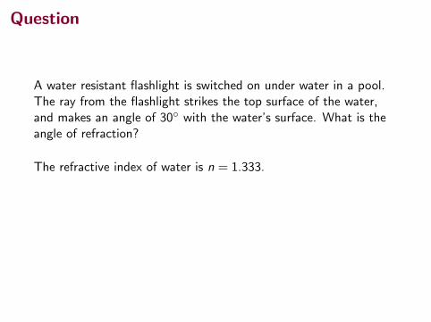
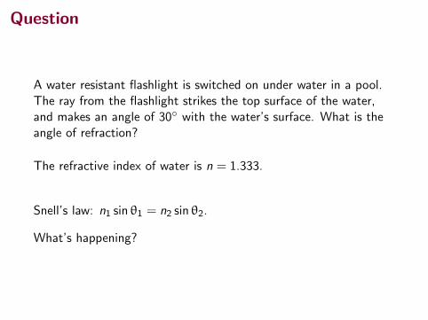
Question
A water resistant flashlight is switched on under water in a pool.The ray from the flashlight strikes the top surface of the water,and makes an angle of 30◦ with the water’s surface. What is theangle of refraction?
The refractive index of water is n = 1.333.
Snell’s law: n1 sin θ1 = n2 sin θ2.
What’s happening?
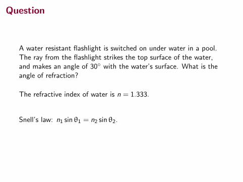
Total Internal Reflection
When a light ray travels from a medium with a higher refractiveindex to one with a lower refractive index, and it strikes theinterface at a sufficiently large incident angle, there is no validsolution for the refracted ray.
In fact, in this case we don’t see one! All of the light is reflected atthe boundary.
This is called total internal reflection.
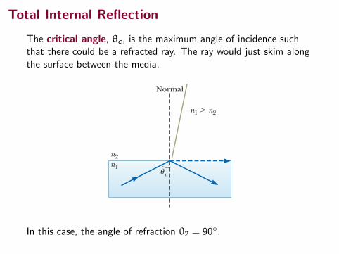
Total Internal Reflection
The critical angle, θc , is the maximum angle of incidence suchthat there could be a refracted ray. The ray would just skim alongthe surface between the media.
1074 Chapter 35 The Nature of Light and the Principles of Ray Optics
the raindrop. In the laboratory, rainbows have been observed in which the light makes more than 30 reflections before exiting the water drop. Because each reflec-tion involves some loss of light due to refraction of part of the incident light out of the water drop, the intensity of these higher-order rainbows is small compared with that of the primary rainbow.
Q uick Quiz 35.4 In photography, lenses in a camera use refraction to form an image on a light-sensitive surface. Ideally, you want all the colors in the light from the object being photographed to be refracted by the same amount. Of the mate-rials shown in Figure 35.21, which would you choose for a single- element camera lens? (a) crown glass (b) acrylic (c) fused quartz (d) impossible to determine
35.8 Total Internal ReflectionAn interesting effect called total internal reflection can occur when light is directed from a medium having a given index of refraction toward one having a lower index of refraction. Consider Figure 35.26a, in which a light ray travels in medium 1 and meets the boundary between medium 1 and medium 2, where n1 is greater than n2. In the figure, labels 1 through 5 indicate various possible direc-tions of the ray consistent with the wave under refraction model. The refracted rays are bent away from the normal because n1 is greater than n 2. At some particular angle of incidence uc , called the critical angle, the refracted light ray moves parallel to the boundary so that u2 5 90° (Fig. 35.26b). For angles of incidence greater than uc , the ray is entirely reflected at the boundary as shown by ray 5 in Figure 35.26a. We can use Snell’s law of refraction to find the critical angle. When u1 5 uc , u2 5 90° and Equation 35.8 gives
n1 sin uc 5 n2 sin 90° 5 n2
sin uc 5n 2
n 1 1 for n 1 . n 2 2 (35.10)
This equation can be used only when n1 is greater than n 2. That is, total internal reflection occurs only when light is directed from a medium of a given index of refraction toward a medium of lower index of refraction. If n1 were less than n2,
Critical angle for total Xinternal reflection
Figure 35.25 This photograph of a rainbow shows a distinct secondary rainbow with the colors reversed.
Mar
k D. P
hilli
ps/P
hoto
Res
earc
hers
, Inc
.
Figure 35.26 (a) Rays travel from a medium of index of refrac-tion n1 into a medium of index of refraction n2, where n2 , n1. (b) Ray 4 is singled out.
As the angle of incidence u1 increases, the angle of refraction u2 increases until u2 is 90! (ray 4). The dashed line indicates that no energy actually propagates in this direction.
The angle of incidence producing an angle of refraction equal to 90! is the critical angle uc . For angles greater than uc, all the energy of the incident light is reflected.
For even larger angles of incidence, total internal reflection occurs (ray 5).
3
Normal Normal
2
4
5
1
u2
u1 uc
n2n1
n2n1
n1 " n2 n1 " n2
a b
In this case, the angle of refraction θ2 = 90◦.

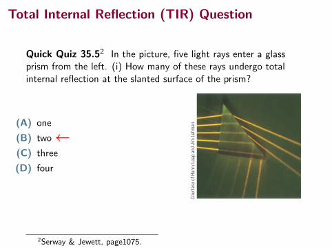
Total Internal Reflection (TIR) Question
Quick Quiz 35.52 In the picture, five light rays enter a glassprism from the left. (i) How many of these rays undergo totalinternal reflection at the slanted surface of the prism?
(A) one
(B) two
(C) three
(D) four
35.8 Total Internal Reflection 1075
Equation 35.10 would give sin uc . 1, which is a meaningless result because the sine of an angle can never be greater than unity. The critical angle for total internal reflection is small when n1 is considerably greater than n2. For example, the critical angle for a diamond in air is 24°. Any ray inside the diamond that approaches the surface at an angle greater than 24° is com-pletely reflected back into the crystal. This property, combined with proper faceting, causes diamonds to sparkle. The angles of the facets are cut so that light is “caught” inside the crystal through multiple internal reflections. These multiple reflections give the light a long path through the medium, and substantial dispersion of colors occurs. By the time the light exits through the top surface of the crystal, the rays associated with different colors have been fairly widely separated from one another. Cubic zirconia also has a high index of refraction and can be made to sparkle very much like a diamond. If a suspect jewel is immersed in corn syrup, the difference in n for the cubic zirconia and that for the corn syrup is small and the critical angle is therefore great. Hence, more rays escape sooner; as a result, the sparkle completely disappears. A real diamond does not lose all its sparkle when placed in corn syrup.
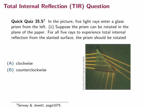
Q uick Quiz 35.5 In Figure 35.27, five light rays enter a glass prism from the left. (i) How many of these rays undergo total internal reflection at the slanted sur-face of the prism? (a) one (b) two (c) three (d) four (e) five (ii) Suppose the prism in Figure 35.27 can be rotated in the plane of the paper. For all five rays to experience total internal reflection from the slanted surface, should the prism be rotated (a) clockwise or (b) counterclockwise?
Figure 35.27 (Quick Quiz 35.5) Five nonparallel light rays enter a glass prism from the left.
Cour
tesy
of H
enry
Lea
p an
d Ji
m L
ehm
an
Example 35.6 A View from the Fish’s Eye
Find the critical angle for an air–water boundary. (Assume the index of refraction of water is 1.33.)
Conceptualize Study Figure 35.26 to understand the concept of total internal reflection and the significance of the critical angle.
Categorize We use concepts developed in this section, so we categorize this example as a substitution problem.
S O L U T I O N
Apply Equation 35.10 to the air–water interface:
sin uc 5n 2
n 15
1.001.33
5 0.752
uc 5 48.88
What if a fish in a still pond looks upward toward the water’s surface at different angles relative to the surface as in Figure 35.28? What does it see?
Answer Because the path of a light ray is reversible, light traveling from medium 2 into medium 1 in Figure 35.26a follows the paths shown, but in the opposite direction. A fish looking upward toward the water surface as in Figure 35.28 can see out of the water if it looks toward the surface at an angle less than the critical angle. Therefore, when the fish’s line of vision makes an angle of u 5 40° with the normal to the surface, for example, light from above the water reaches the fish’s eye. At u 5 48.8°, the critical angle for water, the light has to skim along the water’s surface before being refracted to the fish’s eye; at this angle, the fish can, in principle, see the entire shore of the pond. At angles greater than the critical angle, the light reaching the fish comes by means of total internal reflection at the surface. Therefore, at u 5 60°, the fish sees a reflection of the bottom of the pond.
WHAT IF ?
u
Figure 35.28 (Example 35.6) What If? A fish looks upward toward the water surface.
Optical FibersAnother interesting application of total internal reflection is the use of glass or trans-parent plastic rods to “pipe” light from one place to another. As indicated in Figure 35.29 (page 1076), light is confined to traveling within a rod, even around curves, as the result of successive total internal reflections. Such a light pipe is flexible
2Serway & Jewett, page1075.
Total Internal Reflection (TIR) Question
Quick Quiz 35.52 In the picture, five light rays enter a glassprism from the left. (i) How many of these rays undergo totalinternal reflection at the slanted surface of the prism?
(A) one
(B) two←(C) three
(D) four
35.8 Total Internal Reflection 1075
Equation 35.10 would give sin uc . 1, which is a meaningless result because the sine of an angle can never be greater than unity. The critical angle for total internal reflection is small when n1 is considerably greater than n2. For example, the critical angle for a diamond in air is 24°. Any ray inside the diamond that approaches the surface at an angle greater than 24° is com-pletely reflected back into the crystal. This property, combined with proper faceting, causes diamonds to sparkle. The angles of the facets are cut so that light is “caught” inside the crystal through multiple internal reflections. These multiple reflections give the light a long path through the medium, and substantial dispersion of colors occurs. By the time the light exits through the top surface of the crystal, the rays associated with different colors have been fairly widely separated from one another. Cubic zirconia also has a high index of refraction and can be made to sparkle very much like a diamond. If a suspect jewel is immersed in corn syrup, the difference in n for the cubic zirconia and that for the corn syrup is small and the critical angle is therefore great. Hence, more rays escape sooner; as a result, the sparkle completely disappears. A real diamond does not lose all its sparkle when placed in corn syrup.
Q uick Quiz 35.5 In Figure 35.27, five light rays enter a glass prism from the left. (i) How many of these rays undergo total internal reflection at the slanted sur-face of the prism? (a) one (b) two (c) three (d) four (e) five (ii) Suppose the prism in Figure 35.27 can be rotated in the plane of the paper. For all five rays to experience total internal reflection from the slanted surface, should the prism be rotated (a) clockwise or (b) counterclockwise?
Figure 35.27 (Quick Quiz 35.5) Five nonparallel light rays enter a glass prism from the left.
Cour
tesy
of H
enry
Lea
p an
d Ji
m L
ehm
an
Example 35.6 A View from the Fish’s Eye
Find the critical angle for an air–water boundary. (Assume the index of refraction of water is 1.33.)
Conceptualize Study Figure 35.26 to understand the concept of total internal reflection and the significance of the critical angle.
Categorize We use concepts developed in this section, so we categorize this example as a substitution problem.
S O L U T I O N
Apply Equation 35.10 to the air–water interface:
sin uc 5n 2
n 15
1.001.33
5 0.752
uc 5 48.88
What if a fish in a still pond looks upward toward the water’s surface at different angles relative to the surface as in Figure 35.28? What does it see?
Answer Because the path of a light ray is reversible, light traveling from medium 2 into medium 1 in Figure 35.26a follows the paths shown, but in the opposite direction. A fish looking upward toward the water surface as in Figure 35.28 can see out of the water if it looks toward the surface at an angle less than the critical angle. Therefore, when the fish’s line of vision makes an angle of u 5 40° with the normal to the surface, for example, light from above the water reaches the fish’s eye. At u 5 48.8°, the critical angle for water, the light has to skim along the water’s surface before being refracted to the fish’s eye; at this angle, the fish can, in principle, see the entire shore of the pond. At angles greater than the critical angle, the light reaching the fish comes by means of total internal reflection at the surface. Therefore, at u 5 60°, the fish sees a reflection of the bottom of the pond.
WHAT IF ?
u
Figure 35.28 (Example 35.6) What If? A fish looks upward toward the water surface.
Optical FibersAnother interesting application of total internal reflection is the use of glass or trans-parent plastic rods to “pipe” light from one place to another. As indicated in Figure 35.29 (page 1076), light is confined to traveling within a rod, even around curves, as the result of successive total internal reflections. Such a light pipe is flexible
2Serway & Jewett, page1075.
Total Internal Reflection (TIR) Question
Quick Quiz 35.53 In the picture, five light rays enter a glassprism from the left. (ii) Suppose the prism can be rotated in theplane of the paper. For all five rays to experience total internalreflection from the slanted surface, the prism should be rotated
(A) clockwise
(B) counterclockwise
35.8 Total Internal Reflection 1075
Equation 35.10 would give sin uc . 1, which is a meaningless result because the sine of an angle can never be greater than unity. The critical angle for total internal reflection is small when n1 is considerably greater than n2. For example, the critical angle for a diamond in air is 24°. Any ray inside the diamond that approaches the surface at an angle greater than 24° is com-pletely reflected back into the crystal. This property, combined with proper faceting, causes diamonds to sparkle. The angles of the facets are cut so that light is “caught” inside the crystal through multiple internal reflections. These multiple reflections give the light a long path through the medium, and substantial dispersion of colors occurs. By the time the light exits through the top surface of the crystal, the rays associated with different colors have been fairly widely separated from one another. Cubic zirconia also has a high index of refraction and can be made to sparkle very much like a diamond. If a suspect jewel is immersed in corn syrup, the difference in n for the cubic zirconia and that for the corn syrup is small and the critical angle is therefore great. Hence, more rays escape sooner; as a result, the sparkle completely disappears. A real diamond does not lose all its sparkle when placed in corn syrup.
Q uick Quiz 35.5 In Figure 35.27, five light rays enter a glass prism from the left. (i) How many of these rays undergo total internal reflection at the slanted sur-face of the prism? (a) one (b) two (c) three (d) four (e) five (ii) Suppose the prism in Figure 35.27 can be rotated in the plane of the paper. For all five rays to experience total internal reflection from the slanted surface, should the prism be rotated (a) clockwise or (b) counterclockwise?
Figure 35.27 (Quick Quiz 35.5) Five nonparallel light rays enter a glass prism from the left.
Cour
tesy
of H
enry
Lea
p an
d Ji
m L
ehm
an
Example 35.6 A View from the Fish’s Eye
Find the critical angle for an air–water boundary. (Assume the index of refraction of water is 1.33.)
Conceptualize Study Figure 35.26 to understand the concept of total internal reflection and the significance of the critical angle.
Categorize We use concepts developed in this section, so we categorize this example as a substitution problem.
S O L U T I O N
Apply Equation 35.10 to the air–water interface:
sin uc 5n 2
n 15
1.001.33
5 0.752
uc 5 48.88
What if a fish in a still pond looks upward toward the water’s surface at different angles relative to the surface as in Figure 35.28? What does it see?
Answer Because the path of a light ray is reversible, light traveling from medium 2 into medium 1 in Figure 35.26a follows the paths shown, but in the opposite direction. A fish looking upward toward the water surface as in Figure 35.28 can see out of the water if it looks toward the surface at an angle less than the critical angle. Therefore, when the fish’s line of vision makes an angle of u 5 40° with the normal to the surface, for example, light from above the water reaches the fish’s eye. At u 5 48.8°, the critical angle for water, the light has to skim along the water’s surface before being refracted to the fish’s eye; at this angle, the fish can, in principle, see the entire shore of the pond. At angles greater than the critical angle, the light reaching the fish comes by means of total internal reflection at the surface. Therefore, at u 5 60°, the fish sees a reflection of the bottom of the pond.
WHAT IF ?
u
Figure 35.28 (Example 35.6) What If? A fish looks upward toward the water surface.
Optical FibersAnother interesting application of total internal reflection is the use of glass or trans-parent plastic rods to “pipe” light from one place to another. As indicated in Figure 35.29 (page 1076), light is confined to traveling within a rod, even around curves, as the result of successive total internal reflections. Such a light pipe is flexible
3Serway & Jewett, page1075.

Total Internal Reflection (TIR) Question
Quick Quiz 35.53 In the picture, five light rays enter a glassprism from the left. (ii) Suppose the prism can be rotated in theplane of the paper. For all five rays to experience total internalreflection from the slanted surface, the prism should be rotated
(A) clockwise
(B) counterclockwise←
35.8 Total Internal Reflection 1075
Equation 35.10 would give sin uc . 1, which is a meaningless result because the sine of an angle can never be greater than unity. The critical angle for total internal reflection is small when n1 is considerably greater than n2. For example, the critical angle for a diamond in air is 24°. Any ray inside the diamond that approaches the surface at an angle greater than 24° is com-pletely reflected back into the crystal. This property, combined with proper faceting, causes diamonds to sparkle. The angles of the facets are cut so that light is “caught” inside the crystal through multiple internal reflections. These multiple reflections give the light a long path through the medium, and substantial dispersion of colors occurs. By the time the light exits through the top surface of the crystal, the rays associated with different colors have been fairly widely separated from one another. Cubic zirconia also has a high index of refraction and can be made to sparkle very much like a diamond. If a suspect jewel is immersed in corn syrup, the difference in n for the cubic zirconia and that for the corn syrup is small and the critical angle is therefore great. Hence, more rays escape sooner; as a result, the sparkle completely disappears. A real diamond does not lose all its sparkle when placed in corn syrup.
Q uick Quiz 35.5 In Figure 35.27, five light rays enter a glass prism from the left. (i) How many of these rays undergo total internal reflection at the slanted sur-face of the prism? (a) one (b) two (c) three (d) four (e) five (ii) Suppose the prism in Figure 35.27 can be rotated in the plane of the paper. For all five rays to experience total internal reflection from the slanted surface, should the prism be rotated (a) clockwise or (b) counterclockwise?
Figure 35.27 (Quick Quiz 35.5) Five nonparallel light rays enter a glass prism from the left.
Cour
tesy
of H
enry
Lea
p an
d Ji
m L
ehm
an
Example 35.6 A View from the Fish’s Eye
Find the critical angle for an air–water boundary. (Assume the index of refraction of water is 1.33.)
Conceptualize Study Figure 35.26 to understand the concept of total internal reflection and the significance of the critical angle.
Categorize We use concepts developed in this section, so we categorize this example as a substitution problem.
S O L U T I O N
Apply Equation 35.10 to the air–water interface:
sin uc 5n 2
n 15
1.001.33
5 0.752
uc 5 48.88
What if a fish in a still pond looks upward toward the water’s surface at different angles relative to the surface as in Figure 35.28? What does it see?
Answer Because the path of a light ray is reversible, light traveling from medium 2 into medium 1 in Figure 35.26a follows the paths shown, but in the opposite direction. A fish looking upward toward the water surface as in Figure 35.28 can see out of the water if it looks toward the surface at an angle less than the critical angle. Therefore, when the fish’s line of vision makes an angle of u 5 40° with the normal to the surface, for example, light from above the water reaches the fish’s eye. At u 5 48.8°, the critical angle for water, the light has to skim along the water’s surface before being refracted to the fish’s eye; at this angle, the fish can, in principle, see the entire shore of the pond. At angles greater than the critical angle, the light reaching the fish comes by means of total internal reflection at the surface. Therefore, at u 5 60°, the fish sees a reflection of the bottom of the pond.
WHAT IF ?
u
Figure 35.28 (Example 35.6) What If? A fish looks upward toward the water surface.
Optical FibersAnother interesting application of total internal reflection is the use of glass or trans-parent plastic rods to “pipe” light from one place to another. As indicated in Figure 35.29 (page 1076), light is confined to traveling within a rod, even around curves, as the result of successive total internal reflections. Such a light pipe is flexible
3Serway & Jewett, page1075.
Application of TIR: Optical Fibers
1076 Chapter 35 The Nature of Light and the Principles of Ray Optics
Figure 35.31 (a) Strands of glass optical fibers are used to carry voice, video, and data signals in telecommunication networks. (b) A bundle of optical fibers is illuminated by a laser.
Denn
is O’
Clai
r/Ge
tty I
mag
es
a b
Hank
Mor
gan/
Phot
o Re
sear
cher
s, In
c.
Figure 35.29 Light travels in a curved transparent rod by mul-tiple internal reflections.
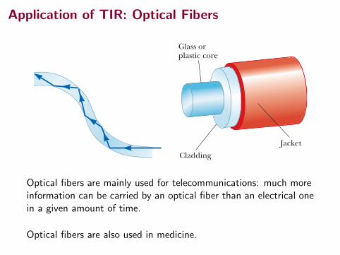
Glass orplastic core
CladdingJacket
Figure 35.30 The construction of an optical fiber. Light travels in the core, which is surrounded by a cladding and a protective jacket.
if thin fibers are used rather than thick rods. A flexible light pipe is called an opti-cal fiber. If a bundle of parallel fibers is used to construct an optical transmission line, images can be transferred from one point to another. Part of the 2009 Nobel Prize in Physics was awarded to Charles K. Kao (b. 1933) for his discovery of how to transmit light signals over long distances through thin glass fibers. This discovery has led to the development of a sizable industry known as fiber optics. A practical optical fiber consists of a transparent core surrounded by a cladding, a material that has a lower index of refraction than the core. The combination may be surrounded by a plastic jacket to prevent mechanical damage. Figure 35.30 shows a cutaway view of this construction. Because the index of refraction of the cladding is less than that of the core, light traveling in the core experiences total internal reflection if it arrives at the interface between the core and the cladding at an angle of incidence that exceeds the critical angle. In this case, light “bounces” along the core of the optical fiber, losing very little of its intensity as it travels. Any loss in intensity in an optical fiber is essentially due to reflections from the two ends and absorption by the fiber material. Optical fiber devices are particularly useful for viewing an object at an inaccessible location. For example, physicians often use such devices to examine internal organs of the body or to perform surgery with-out making large incisions. Optical fiber cables are replacing copper wiring and coaxial cables for telecommunications because the fibers can carry a much greater volume of telephone calls or other forms of communication than electrical wires can. Figure 35.31a shows a bundle of optical fibers gathered into an optical cable that can be used to carry communication signals. Figure 35.31b shows laser light follow-ing the curves of a coiled bundle by total internal reflection. Many computers and other electronic equipment now have optical ports as well as electrical ports for transferring information.
Definition
The index of refraction n of a medium is defined by the ratio
n ;cv
(35.4)
where c is the speed of light in vacuum and v is the speed of light in the medium.
Summary
1076 Chapter 35 The Nature of Light and the Principles of Ray Optics
Figure 35.31 (a) Strands of glass optical fibers are used to carry voice, video, and data signals in telecommunication networks. (b) A bundle of optical fibers is illuminated by a laser.
Denn
is O’
Clai
r/Ge
tty I
mag
es
a b
Hank
Mor
gan/
Phot
o Re
sear
cher
s, In
c.
Figure 35.29 Light travels in a curved transparent rod by mul-tiple internal reflections.
Glass orplastic core
CladdingJacket
Figure 35.30 The construction of an optical fiber. Light travels in the core, which is surrounded by a cladding and a protective jacket.
if thin fibers are used rather than thick rods. A flexible light pipe is called an opti-cal fiber. If a bundle of parallel fibers is used to construct an optical transmission line, images can be transferred from one point to another. Part of the 2009 Nobel Prize in Physics was awarded to Charles K. Kao (b. 1933) for his discovery of how to transmit light signals over long distances through thin glass fibers. This discovery has led to the development of a sizable industry known as fiber optics. A practical optical fiber consists of a transparent core surrounded by a cladding, a material that has a lower index of refraction than the core. The combination may be surrounded by a plastic jacket to prevent mechanical damage. Figure 35.30 shows a cutaway view of this construction. Because the index of refraction of the cladding is less than that of the core, light traveling in the core experiences total internal reflection if it arrives at the interface between the core and the cladding at an angle of incidence that exceeds the critical angle. In this case, light “bounces” along the core of the optical fiber, losing very little of its intensity as it travels. Any loss in intensity in an optical fiber is essentially due to reflections from the two ends and absorption by the fiber material. Optical fiber devices are particularly useful for viewing an object at an inaccessible location. For example, physicians often use such devices to examine internal organs of the body or to perform surgery with-out making large incisions. Optical fiber cables are replacing copper wiring and coaxial cables for telecommunications because the fibers can carry a much greater volume of telephone calls or other forms of communication than electrical wires can. Figure 35.31a shows a bundle of optical fibers gathered into an optical cable that can be used to carry communication signals. Figure 35.31b shows laser light follow-ing the curves of a coiled bundle by total internal reflection. Many computers and other electronic equipment now have optical ports as well as electrical ports for transferring information.
Definition
The index of refraction n of a medium is defined by the ratio
n ;cv
(35.4)
where c is the speed of light in vacuum and v is the speed of light in the medium.
Summary
Optical fibers are mainly used for telecommunications: much moreinformation can be carried by an optical fiber than an electrical onein a given amount of time.
Optical fibers are also used in medicine.
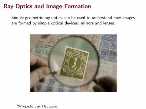
Ray Optics and Image Formation
Simple geometric ray optics can be used to understand how imagesare formed by simple optical devices: mirrors and lenses.
1Wikipedia user Heptagon.
Images Formed by Flat Mirrors
When we see an object “in the mirror”, we are not actually seeingsomething that is behind the mirror.
We are seeing an image of an object that is placed in front of themirror.
The image seems to be the same distance behind the mirror as theobject is in front of it.
The image seems to be the same size as the object.
This is not true for all optical devices, but we can work out thingsabout how the image will form for many different optical devices.
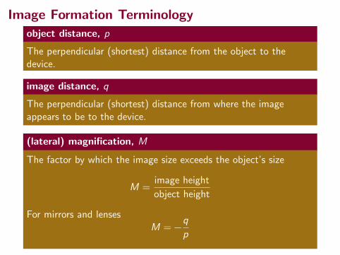
Image Formation Terminology
object distance, p
The perpendicular (shortest) distance from the object to thedevice.
image distance, q
The perpendicular (shortest) distance from where the imageappears to be to the device.
(lateral) magnification, M
The factor by which the image size exceeds the object’s size
M =image height
object height
For mirrors and lensesM = −
q
p
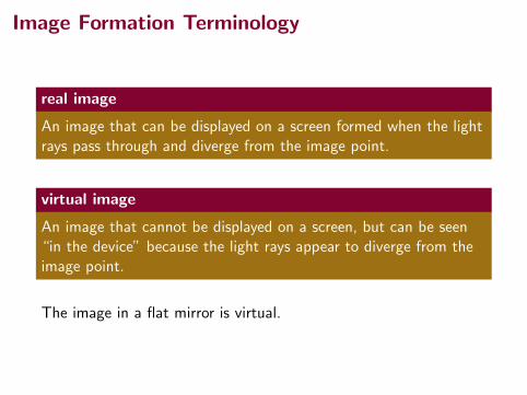
Image Formation Terminology
real image
An image that can be displayed on a screen formed when the lightrays pass through and diverge from the image point.
virtual image
An image that cannot be displayed on a screen, but can be seen“in the device” because the light rays appear to diverge from theimage point.
The image in a flat mirror is virtual.
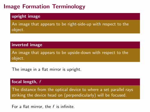
Image Formation Terminology
upright image
An image that appears to be right-side-up with respect to theobject.
inverted image
An image that appears to be upside-down with respect to theobject.
The image in a flat mirror is upright.
focal length, f
The distance from the optical device to where a set parallel raysstriking the device head on (perpendicularly) will be focused.
For a flat mirror, the f is infinite.
Summary
• dispersion
• total internal reflection
• image terminology
Homework Serway & Jewett:
• Carefully read Chapter 36. (over the next few days)
• Ch 36, onward from page 1123. OQs: 13