Embed Size (px)
Citation preview

Optimal Heat Exchanger Network Synthesis Including the Heat Transfer Equipment Design Proceedings of European Congress of Chemical Engineering (ECCE-6) Copenhagen, 16-20 September 2007
Optimal Heat Exchanger Network Synthesis Including Heat Transfer Equipment Design
M. A. S. S. Ravagnani,a J. A. Caballerob
aDepartment of Chemical Engineering, State University of Maringá,87020-900, Maringá – PR - Brazil bDepartment of Chemical Engineering, University of Alicante, 03690, Alicante, Spain
Abstract This paper presents an optimisation model for the synthesis of heat exchanger networks (HEN) including the detailed design of the equipments formulated as a decomposition method. Shell and tube pressure drops and fouling are considered, as well as mechanical aspects, like shell and tube bundle diameters, internal and external diameter of tubes, number of tubes, number of baffles, number of shells, tube length, tube arrangement and the fluid allocation in the heat exchanger. The optimisation model is based on area, energy and pumping costs. The algorithm combines two distinct models, in a decomposition method, a Mixed Integer Non-Linear Programming (MINLP) superstructure simultaneous optimisation model for the heat exchanger network synthesis considering stream splitting, assuming isothermal mixing and a MINLP model for the detailed equipment design, following rigorously the standards of the TEMA. Two examples from the literature are used to test the algorithm developed, and the results confirm the achievement of the optimum HEN configuration with the detailed heat exchangers design, following the TEMA standards.
Keywords: Optimisation, heat exchanger network synthesis, heat exchanger design, Mixed Integer Non Linear Programming, Mathematical Programming. Introduction Heat exchanger network (HEN) synthesis has been a well studied subject over the last 40 years. As a research theme, numerous papers have been published focusing distinct methods and techniques of synthesis. Heat recovery systems were always subject of interest in synthesis studies. After the first energy crisis, during the seventies, which can be considered as the driving force of the heat exchanger network synthesis study, as a research area, a considerable increase occurred in the number of papers related to the subject. Industries, universities and research centres became to find solutions to minimize the use of thermal energy from the burn of combustibles, like crude oil.

Ravagnani and Caballero 2
Many studies and methodologies were proposed to make possible the energy recovery between process streams, minimizing the utilities consumption, the number of heat transfer equipment and the gaseous and liquid pollutant emissions from the combustible burn and water usage. Gundersen and Naess (1988) and Furman and Sahinidis (2002) published complete reviews on HEN synthesis. Important research lines have being proposed, like Pinch Analysis and Mathematical Programming. Pinch Analysis uses thermodynamic concepts and heuristics, as can be seen in the works of Linnhoff and Flower (1978), Linnhoff et al. (1979, 1982), Linnhoff and Hindmarsh (1983) and Linnhoff (1993, 1994). In Mathematical Programming the HEN synthesis is treated as an optimisation problem. According to Grossmann et al. (2000), a gradual evolution has occurred relative to Mathematical Programming method utilization, from the sequential approaches, where one aims to obtain the problem solution step by step, as can be seen in the papers of Cerda and Westerberg (1983), Papoulias and Grossmann (1983), Floudas et al. (1986), Colberg and Morari (1990) and Gundersen and Grossmann (1990), to the works using simultaneous optimisation, where all of the variables are optimised simultaneously, as can be seen in Yee and Grossmann (1990), Ciric and Floudas (1991), Quesada and Grossmann (1993), Zamora and Grossmann (1998) and Bjork and Westerlund (2002). The HEN synthesis MINLP problem formulations are highly non-linear, and some papers, as Daichendt and Grossmann (1994), Quesada and Grossmann (1993) and Zamora and Grossmann (1998) were published using global optimisation, trying to avoid local minima. Although conventional MINLP methods are based integrally on algebraic discrete/continuous optimisation problems, a model using Generalized Disjunctive Programming (Raman and Grossmann, 1994, Turkay and Grossmann, 1996 and Lee and Grossmann, 2000) can combine logical and algebraic equations, to represent discrete decisions. Nevertheless, the majority of published papers in HEN synthesis consider constant heat transfer coefficients. This consideration can achieve solutions very far from the point of view of industrial application. A few papers incorporate the design of the heat exchangers in the HEN synthesis. In the works of Polley et al (1990), Panjeh Shahi (1992) and Polley and Panjeh Shahi (1992), a relationship between the pressure drop and the individual heat transfer coefficients was proposed using the methods of Kern (1950) and Bell Delaware (Taborek, 1983). Ravagnani et al. (2003) presented a methodology for the synthesis of HEN including the thermo-hydraulic design of the heat exchangers. The HEN synthesis is accomplished by using Pinch Analysis. The network is evolved by identification and loop breaking. After the evolution, the heat exchangers of the network are designed considering pressure drops and fouling with the Bell-Delaware for the shell side.
Frausto-Hernandez et al. (2003) presented a MINLP model to the synthesis of HEN considering pressure drop effects. Heat transfer coefficients are calculated based on the fixed pressure drops, using the equations proposed by Panjeh Shahi (1992), Polley and Panjeh Shahi (1992) and Polley et al. (1990).
Mizutani et al. (2003a) presented a model of Mathematical Programming to the design of shell and tube heat exchangers. The model is based on the Generalized Disjunctive Programming (GDP) with a MINLP formulation and uses the Bell-

Optimal Heat Exchanger Network Synthesis Including the Heat Transfer Equipment Design 3
Delaware equations to calculate heat transfer and pressure drop at the shell side. The objective function consists of the area and pumping costs. Based on this work, Mizutani et al. (2003b) developed a model for the synthesis of HEN based on the heat exchanger design model (Mizutani et al., 2003a). To the network synthesis, the logic based outer approximation method of Turkay and Grossmann (1996) was used.
Ravagnani and Caballero (2007a) proposed a mathematical model to find the best shell-and-tube heat exchanger configuration, using the Bell-Delaware method for the shell side thermal calculation and following rigorously the standards of the Tubular Exchangers Manufacturers Association (TEMA). A tube counting table was used in the optimisation model in a GDP proposition. Some variables are obtained by using the proposition of Mizutani et al. (2003a), but, alternatively, pressure drops and fouling limits are considered in the model as inequalities constraints. Also, some heat exchanger parameters are considered as optimisation variables, as the tube length, number of shells and baffle spacing.
In the present paper an algorithm is proposed to the HEN synthesis considering the detailed design of the heat exchangers, as presented in Ravagnani and Caballero (2007b). A bi-level decomposition method considers first an initial HEN structure, obtained with an algorithm similar to the proposed by Yee and Grossmann (1990) HEN synthesis method, based on a stage-wise superstructure representation, considering stream splitting and assuming isothermal mixing, and constant heat transfer coefficients. For this initial HEN configuration, the heat exchangers are detailed designed and the streams heat transfer coefficient recalculated. With these new values, a HEN synthesis configuration is obtained and the global cost is compared. The procedure continue until in two consecutive iterations the objective function of the structure with detailed heat exchangers calculations is worst than the previous structure involving detailed heat exchangers calculations. This stopping criteria is heuristic, and eventually it is possible to get trapped in a local optimum. It is also possible perform two or three more iterations in order to check if a better solution is obtained, but experience show that this is not usually the case. The mixed integer non-linear programming (MINLP) model proposed in Ravagnani and Caballero (2007a) is used for the design of shell and tube heat exchangers. The model rigorously follows the Standards of TEMA and Bell Delaware Method and is used to the shell side calculations. Mechanical design features (shell and tube bundle diameters, internal and external tube diameters, tubes length, pitch and arrangement, number of shells, number of tubes and tube passes) and thermal-hydraulic variables (heat, area, individual and global heat transfer coefficient, shell and tube pressure drops and fouling) are variables to be optimised. The equipments are designed under pressure drop and fouling limits. The great contribution of this paper is, besides the incorporation of the equipment detailed design and the achievement of optimal mechanical and thermo-hydraulical variables, the warrantee of the use of the standards of TEMA. The problem is solved using GAMS. Problem formulation Given a set of hot and cold streams with their supply and target temperatures, flow rates and physical properties (density, viscosity, heat capacity and thermal conductivity), pressure drop and fouling limits, as well as hot and cold utilities with

Ravagnani and Caballero 4
their temperatures and corresponding costs, the objective is to find the HEN with the detailed heat exchangers design concerning the minimum global annual cost, considering utility, area and pumping costs. The problem consists in to find the best HEN configuration and to optimise the heat exchangers variables tube inside diameter (din), tube outside diameter (dex), tube arrangement (arr), tube pitch (pt), tube length (L), number of tubes (Nt), number of shells (NS), shell external diameter (Ds), tube bundle diameter (Dotl), number of baffles (Nb), baffle spacing (ls), heat duty (Q), heat exchange area (A), tube-side and shell-side film coefficients (ht and hs), dirty and clean global heat transfer coefficient (Ud and Uc), pressure drops (∆Pt and ∆Ps), fouling factor (rd) and the hot and cold fluids allocation (tubes or shell). For the problem solution, a HEN synthesis an algorithm similar to the stage-wise superstructure representation of Yee and Grossmann (1990) is proposed together with the heat exchangers design model presented in Ravagnani and Caballero (2007a) for each network equipment, to find the minimum global annual cost, comprising area, utilities and pumping costs. Isothermal mixing in each stage of the superstructure is assumed to become some of the problems constraints linear. Stream splitting is considered in the HEN synthesis model. Figure 1 presents a superstructure for a problem with 4 streams, based in the work of Yee and Grossmann (1990). The superstructure comprises stages, within each of which heat exchange occurs between every hot stream and cold stream. Heaters and coolers are placed at the ends of the streams, and isothermal mixing junctions are assumed, for simplicity. As recommended by Yee and Grossmann (1990), the number of stages is the maximum of the number of hot or cold streams.
H1
H2
C1
C2
Streams Stage 1 Stage 2
Figure 1 – Proposed superstructure in a four streams problem Proposed Algorithm The algorithm proposed in the present paper consists of solving successively a stage-wise superstructure model similar to the Yee and Grossmann (1990) for the HEN optimal configuration and the MINLP model of Ravagnani and Caballero (2007a) for the optimal heat exchangers design. Six steps are used: Step 1: Generate an initial HEN configuration by using the superstructure model considering stream splitting, assuming isothermal mixing and constant heat

Optimal Heat Exchanger Network Synthesis Including the Heat Transfer Equipment Design 5
transfer coefficients. Assume this HEN configuration as an initial guess to the optimization problem. Set k=0. Step 2: Solve the MINLP model of Ravagnani and Caballero (2007a) for each heat exchanger and calculate the global annual cost of the generated HEN. Set k= k +1. The result of this problem is an upper bound of the optimal solution of the HEN Step 3: Calculate the streams individual heat transfer coefficients considering an average value proportional to the heat duty and the hot and cold fluid film coefficients of each heat exchanger in the stream. Step 4: Using these new heat transfer coefficients solve again the problem obtained in step 1. If the HEN is the same as the initial one, stop. Otherwise, go to step 5. Step 5: Solve the MINLP model of Ravagnani and Caballero (2007a) for each heat exchanger and calculate the global annual cost of the generated HEN. Set k= k +1. Step 6: If the object value is higher than the actual upper bound, stop. Otherwise, go to step 7. Step 7: Calculate the streams individual heat transfer coefficients considering an average value proportional to the heat duty and the hot and cold fluid film coefficients of each heat exchanger in the stream. Step 8: Using these new heat transfer coefficients generate a HEN configuration by using the superstructure model considering stream splitting, assuming isothermal mixing. If the HEN is the same as the anterior one, stop. Otherwise, go to step 9. Step 9: Solve the MINLP model of Ravagnani and Caballero (2007a) for each heat exchanger and calculate the global annual cost of the generated HEN. Set k= k +1. If the value is higher than the actual one, stop. Otherwise, go to step 7. Figure 2 presents a flowchart that represents the developed algorithm.
Case Studies Two examples are presented to illustrate the potential of applicability of the
proposed algorithm for the synthesis of HEN considering the detailed design of the heat exchangers. The objective function for the examples consider area, utilities and pumping costs.
Case 1: This example was extracted from Mizutani et al. (2003b). The objective
is to find the optimal heat exchanger network configuration with the equipments detailed design. The problem has 2 hot and 2 cold streams and a hot and a cold utility are available. Temperatures, flow rate and physical properties of the streams and utilities, pumping, area and cost data are shown on Table 1.
Ravagnani and Caballero 6
Generate an initial HEN configuration by using the superstructure modelconsidering constant heat transfer coefficients. Set k=0.
Solve the MINLP model of the detailed design for each heat exchanger andcalculate the global annual cost of the generated HEN.
Calculate the individual heat transfer coefficients for each stream.
Generate a HEN configuration by using the superstructure modelconsidering the calculated heat transfer coefficients. Set k= k +1.
Is the HENthe same as the
anterior one?
StopSolve the MINLP model of the detailed design for
each heat exchanger and calculate the global annualcost of the generated HEN.
Y
N
Is the HEN globalcost higher than the
current one?N
Y
Figure 2 – Developed algorithm
Also, as an initial estimative, overall heat transfer coefficients are assumed to be
444 W/m2K, for stream-stream and stream-utility matches. By using the proposed algorithm, in the first step a network configuration is generated as an initial guess considering the superstructure model similar to the Yee and Grossmann (1990). Figure 3 shows this initial configuration, considering stream splitting. This consideration makes the HEN structure different from the obtained in the paper of Mizutani et al. (2003b).
Following the proposed algorithm, for the network structure, the heat exchangers are designed, by using the MINLP model, proposed by Ravagnani and Caballero (2007a). The area and pressure drop values are used to calculate the HEN

Optimal Heat Exchanger Network Synthesis Including the Heat Transfer Equipment Design 7
global annual cost. The value obtained is 96,387.435 $/year. Table 2 presents the details of the equipments design.
Table 1 – Streams and cost data Stream Tin
(K) Tout (K)
m (kg/s)
µ (kg/ms)
ρ (kg/m3)
Cp (J/kgK)
k (W/mK)
∆P (kPa)
rd (W/mK)
H1 368 348 8.15 2.4e-4 634 2454 0.114 68.95 1.7e-4 H2 353 348 81.5 2.4e-4 634 2454 0.114 68.95 1.7e-4 C1 303 363 16.3 2.4e-4 634 2454 0.114 68.95 1.7e-4 C2 333 343 20.4 2.4e-4 634 2454 0.114 68.95 1.7e-4 UQ 500 500 UF 300 320 Area cost = 1000 + 60.A0.6, A in m2 Pumping cost = 0.7(∆Ptmt/ρt + ∆Psms/ρs), ∆P in Pa, m in kg/s and ρ in kg/m3 Hot utility cost = 60 $/kW.year Cold utility cost = 6 $/kW.year Initial overall heat transfer coefficients = 444 W/m2K
E1
H1
E2
368 348
353 348
363 303
343 333
H1
H2
C1
C2
(1500 kW)
(100 kW)(400 kW )
(900 kW)
325.5
335
E3
20
200180
20
40
50
Figure 3 – Case 1 HEN initial configuration
With the hot and cold heat transfer coefficients and the heat duty for each
heat exchanger in the network, the streams individual film coefficients are calculated. With these streams heat transfer individual coefficient, the HEN synthesis superstructure model is used to generate a new heat exchanger network. Figure 4 presents the new heat exchangers network.
For this new structure, the heat exchangers are designed, by using the MINLP model, proposed by Ravagnani and Caballero (2007a). The area and pressure drop values are used to calculate the HEN global annual cost. Table 3 presents the details of the equipment design. The value obtained is 96,013.65 $/year. This value is less than the first HEN cost. So, the procedure must continue. With the hot and cold heat transfer coefficients and the heat duty for each heat exchanger in the network, the streams individual film coefficients are calculated. With these streams heat transfer individual coefficient, the HEN synthesis superstructure model is again used to generate a new HEN, presented in Figure 5.
For this structure the heat exchangers are designed, by using the MINLP model, proposed by Ravagnani and Caballero (2007a). Table 4 presents the details of

Ravagnani and Caballero 8
the equipment design. The value obtained is 96,833.95 $/year. This cost value is higher than the previous one. According to the proposed methodology, the procedure must stop. So, the procedure must finish and the HEN configuration presented in Figure 4 is the best one. Table 5 presents the evolution of the algorithm for this case study.
Table 2 – Case 1 initial HEN detailed equipment design
E1 E2 E3 Area (m2) 53.855 71.203 15.953
Q (W) 400000 900000 100000 MLDT (K) 18.35 35.53 16.45
Ft .9129 0.9847 .9938 Ntp 4 4 2 NS 1 1 1
Ds (m) 0.533 0.787 0.387 Dotl (m) 0.489 0.746 0.356
Nt 246 366 82 Nb 11 3 6
dex (mm) 19.05 25.40 25.40 din (mm) 17.00 23.00 23.00 pt (mm) 25.40 31.75 31.75 L (m) 3.658 2.438 2.438
hs (W/m2ºC) 1276.793 952.245 1058.382 ht (W/m2ºC) 1603.279 1138.379 1241.499 Uc (W/m2ºC) 529.015 415.047 449.817 Ud (W/m2ºC) 443.381 361.281 387.344
∆Pt (kPa) 8698.031 2868.276 1758.181 ∆Ps (kPa) 2124.866 480.992 1152.250
rd (m2ºC/W) 3.65e-4 3.59e-4 3.59e-4 arr square square square
Hot fluid allocation tubes shell tubes Pumping cost ($/year) 126.128 90.573 41.754
Area cost ($/year) 6,128.98 Pumping cost ($/year) 258.455 Utility cost ($/year) 90,000.00
Global annual cost ($/year) 96,387.435
E1
H1
E2
368 348
353 348
363 303
343 333
H1
H2
C1
C2
(1000 kW) (1000 kW)(400 kW)
338
20
200
40
50 H2
(500 kW)
328
Figure 4 – Case 1 second HEN structure

Optimal Heat Exchanger Network Synthesis Including the Heat Transfer Equipment Design 9
E1
H1
E3
368 348
353 348
363 303
343 333
H1
H2
C1
C2
(1000 kW) (900 kW)
(400 kW)
325.5
20
200
40
50
(100 kW)
352.5E2
40
10
Figure 5 – Case 1 third HEN structure
Table 3 – Second Case 1 HEN detailed equipment design
E1 E2 Area (m2) 40.279 78.207
Q (W) 400000 1000000 MLDT (K) 24.66 34.03
Ft .942 0.981 Ntp 1 1 NS 1 1
Ds (m) 0.387 0.787 Dotl (m) 0.356 0.746
Nt 138 402 Nb 34 13
dex (mm) 19.05 25.40 din (mm) 17.00 23.00 pt (mm) 25.40 31.75 L (m) 4.877 2.438
hs (W/m2ºC) 1253.196 1011.032 ht (W/m2ºC) 1462.278 1262.464 Uc (W/m2ºC) 506.567 443.943 Ud (W/m2ºC) 427.504 382.980
∆Pt (kPa) 2151.818 914.384 ∆Ps (kPa) 3918.412 738.935
rd (m2ºC/W) 3.65e-4 3.59e-4 arr square square
Hot fluid allocation shell tubes Pumping cost ($/year) 73.98 95.58
Area cost ($/year) 5,844.09 Pumping cost ($/year) 169.56 Utility cost ($/year) 90,000.00
Global annual cost ($/year) 96,013.65 There are some very important considerations in comparing this algorithm procedure with the proposed in the work of Mizutani et al. (2003b). To compare the proposed procedures in the present paper, a HEN is synthesized without stream splitting. The best network structure is the same as the obtained in Mizutani et al. (2003b) and can be seen in Figure 6. It has two process-to-process heat exchangers

Ravagnani and Caballero 10
and two heaters but with different streams and heat duty allocation, when compared with the best HEN obtained considering stream splitting.
Table 4 – Third Case 1 HEN detailed equipment design
E1 E2 E3 Area (m2) 55.384 48.636 72.954
Q (W) 400000 100000 900000 MLDT (K) 19.57 14.23 35.23
Ft .9045 0.9958 .9861 Ntp 1 1 8 NS 1 1 1
Ds (m) 0.387 0.635 0.737 Dotl (m) 0.356 0.594 0.659
Nt 138 250 500 Nb 34 3 3
dex (mm) 19.05 25.40 19.05 din (mm) 17.00 23.00 17.00 pt (mm) 25.40 31.75 25.40 L (m) 6.706 2.438 2.438
hs (W/m2ºC) 1099.260 248.726 1253.115 ht (W/m2ºC) 1462.278 1846.069 909.036 Uc (W/m2ºC) 479.429 199.753 407.872 Ud (W/m2ºC) 408.013 145.100 355.007
∆Pt (kPa) 2738.570 2237.868 3643.370 ∆Ps (kPa) 3391.288 9.898 1112.435
rd (m2ºC/W) 3.65e-4 2e-3 3.65e-4 arr square square square
Hot fluid allocation shell tubes shell Pumping cost ($/year) 79.802 201.417 116.494
Area cost ($/year) 6,436.24 Pumping cost ($/year) 397.71 Utility cost ($/year) 90,000.00
Global annual cost ($/year) 96,833.95 Table 5 – Case 1 algorithm evolution Global annual cost ($/year) Initial guess (considering constant heat transfer coefficients)
95,969.43
Iteration 1 96,387.44 Iteration 2 96,013.65 Iteration 3 96,833.95
Table 6 presents a comparison between the heat exchangers details. In the work of Mizutani et a. (2003b), it is assumed that all the heat exchangers have one tube passes, to avoid the correction factor to the LMTD calculus, i.e., Ft is equal to 1. In the present paper, the Ft is calculated and it is always less than 1. It means an increase in the heat exchangers area. Also, the designed heat exchangers are in accordance with the standards of TEMA. It does not occur with the Mizutani’s heat exchangers. The authors use, for example, for the internal and external diameter the values of 21.18 and 25.40 mm for the first heat exchanger and 46.58 and 50.80 mm

Optimal Heat Exchanger Network Synthesis Including the Heat Transfer Equipment Design 11
for the second one. Table 7 presents the final results, considering and not considering stream splitting, when compared with the results of Mizutani et al. (2003b). It can be noted that the HEN configuration obtained considering stream splitting has a better objective value when compared with the configuration with no stream splitting, but worst than the obtained by Mizutani et al. (2003b). It can be explained because of the TEMA standards, which give to the problem results closer to the industrial reality. This is one of the contribution of the current paper. Also, it is important to consider the Ft calculus. If Ft is equal to 1, the heat exchangers will have always 1 shell, what is not always true in industrial applications, as will be demonstrated in Case 2.
Table 6 – Heat exchangers details with no stream splitting
HE1 HE2 Mizutani et
al. (2003b) Present paper
Mizutani et al. (2003b)
Present paper
Area (m2) 33.30 36.12 56.20 62.303 Q (W) 400000 400000 1000000 1000000
MLDT (K) 20.42 34.03 Ft 0.931 0.981 Ntp 2 4 NS 1 1
Ds (m) 0.400 0.337 0.650 0.686 Dotl (m) -- 0.305 -- 0.645
Nt 86 90 72 427 Nb 13 98 10 3
dex (mm) 25.40 19.05 50.80 19.05 din (mm) 21.18 17.01 46.58 17.01 pt (mm) -- 25.40 -- 25.04 L (m) -- 6.71 2.438
hs (W/m2ºC) -- 2409.240 -- 1461.136 ht (W/m2ºC) -- 2058.445 -- 1795.721 Uc (W/m2ºC) -- 740.316 -- 583.164 Ud (W/m2ºC) 588.00 582.796 523.00 480.798
∆Pt (kPa) -- 11852.116 -- 8828.816 ∆Ps (kPa) -- 2758.613 -- 1494.899
rd (m2ºC/W) -- 3.65e-4 ----- 3.65e-4 arr square square triangular square
Hot fluid allocation
shell tubes tubes shell
Pumping cost ($/year)
-- 168.784 -- 293.408
Table 7 – Final results for the Case 1 Mizutani et al., 2003b
(no stream splitting and Ft =1)
Present paper considering no stream splitting
Present paper considering
stream splitting Global annual cost
($/year) 95,852.00 96,137.71 96,013.65
Area cost ($/year) 5,608.00 5,675.52 5,844.09 Pumping cost
($/year) 244.00 462.19 169.56
Utility cost ($/year) 90,000.00 90,000.00 90,000.00

Ravagnani and Caballero 12
E1
H1
H2
E2
368 348
353 348
363 303
343 333
H1
H2
C1
C2
(1400 kW)
(100 kW) (400 kW )
(1000 kW)
328
341
Figure 6 – Best HEN configuration with no stream splitting
Case 2: This example was also extracted from Mizutani et al. (2003b). Three hot and three cold process streams are considered, as well as a hot and a cold utility. Stream physical properties, temperatures, flow rate and cost data are shown in Table 8. By using the HEN synthesis superstructure model proposed, similar to the work of Yee and Grossmann (1990), an initial network structure is synthesized, considering constant heat transfer coefficients. This initial heat exchanger network configuration is presented in Figure 7. For this initial structure, the heat exchangers are designed, using the MINLP model proposed by Ravagnani and Caballero (2007a), and the global annual cost is obtained. The equipment details are shown in Table 9.
The next step is to use the individual heat transfer coefficients to calculate the new streams film coefficient, by using an average value considering the stream heat exchangers duty. With these new values, the HEN synthesis procedure is used to generate a new heat exchangers network. The second structure is shown in Figure 8.
Table 8 – Example 2 data Stream Tin
(K) Tout (K)
m (kg/s)
Cp (J/kgK)
k (W/mK)
µ (kg/ms)
ρ (kg/m3)
∆P (KPa)
rd (m2K/W)
H1 423 333 16.3 2454 .114 2.4e-4 634 68.95 1.7e-4 H2 363 333 65.2 2454 .114 2.4e-4 634 68.95 1.7e-4 H3 454 433 32.6 2454 .114 2.4e-4 634 68.95 1.7e-4 C1 293 398 20.4 2454 .114 2.4e-4 634 68.95 1.7e-4 C2 293 373 24.4 2454 .114 2.4e-4 634 68.95 1.7e-4 C3 283 288 65.2 2454 .114 2.4e-4 634 68.95 1.7e-4 UQ 700 700 UF 300 320
Area cost = 1000 + 60.A0.6 ($/year), A in m2 Pumping cost = 1.3(∆Ptmt/ρt + ∆Psms/ρs), ∆P in Pa, m in kg/s and ρ in kg/m3
Cold Utility cost = 6 ($/kW.year) Hot Utility cost = 60 ($/kW.year)
Initial overall heat transfer coefficients = 444 W/m2K

Optimal Heat Exchanger Network Synthesis Including the Heat Transfer Equipment Design 13
H1
H2
H3
C1
C2
C3
423
363
454
398
373
288
360.167
283
293
293380
433
333
333E4
H1
(3600)
(800)
(3150)
(770)
443
E5
(1200)
(430)
353
E1
35.3
4.7 418.74
(20)
1.11
48.89
E2410.82
40
160
80
50
60
160
E3
30
20
398
353
411.75
E6120
40
E7
(880)
m.Cp
Figure 7 – Case 2 initial HEN configuration
The equipments are designed and a new global cost is calculated and compared with the anterior one. Table 10 presents the heat exchangers design. The global cost is 69,165.48 ($/year). This value is less than the previous one. It means that the procedure must continue, and new streams film coefficient must be calculated and a new HEN configuration must be generated. Using the HEN synthesis procedure a new structure is generated and it is the same as presented in Figure 8. So, the procedure must finish, and this HEN is assumed to be the best one. Table 11 shows as the global annual cost varies during the iterations.
H1
H2
H3
C1
C2
C3
423
363
454
398
373
288
360.167
283
293
293
433
333
333
H1
(3600)
(800)
(770)
E5
(400)
(430)
353
E1
32.68
17.32
E2412.25
40
160
80
50
60
160
E4
340.5
301
E3
106.67
53.33
E6
(1680)
m.Cp
(3170)
Figure 8 – Case 2 second HEN configuration

Ravagnani and Caballero 14
Table 9 – Equipment design for the Case 3 initial structure
Global annual cost
($/year)
70,070.18
Area cost ($/year)
21,509.38
Pumping cost ($/year)
2,360.79
Utility cost ($/year)
46,200.00
E1 E2 E3 E4 E5 E6 E7 Area (m2) 3.113 21.789 34.434 2009.89 342.74 1088.04 48.636 Q (kW) 20 430 880 3150 1200 3600 800 Ds (m) 0.205 0.438 0.489 1.118 0.686 1.524 0.635 Dotl (m) 0.173 0.406 0.457 1.073 0.645 1.473 0.594
Ft 0.9867 0.9959 .9906 .8353 0.8052 0.8052 0.9996 NS 1 1 1 4 2 2 1 Ntp 2 1 1 8 4 1 1 Nt 16 112 236 1252 427 2485 250 Nb 11 5 6 29 24 11 3
dex (mm) 25.40 25.40 19.05 19.05 19.05 19.05 25.40 din (mm) 23.00 23.00 17.00 17.00 17.00 16.00 23.00 pt (mm) 31.75 31.75 25.40 25.40 25.40 25.40 31.75
hs (W/m2ºC) 302.457 968.172 1169.844 701.909 1044.546 1132.876 1134.904 ht (W/m2ºC) 1444.917 876.005 1657.401 1050.095 1031.371 887.103 1544.258
L (m) 2.438 2.438 2.438 6.706 6.706 3.658 2.438 Uc (W/m2ºC) 224.277 372.589 515.854 343.779 406.281 381.720 503.966 Ud (W/m2ºC) 207.584 328.679 434.099 305.443 353.802 334.351 107.918
∆Pt (kPa) 2512.266 387.919 1831.848 41576.000 9982.106 6827.218 1469.051 ∆Ps (kPa) 315.890 850.874 1080.868 2517.088 3888.766 1353.104 633.456
rd (m2ºC/W) 3.59e-4 3.59e-4 3.65e-4 3.65e-4 3.65e-4 3.71e-4 7e-3 arr square square square square square square square
Hot fluid allocation
tubes tubes tubes shell shell shell shell
Pumping cost ($/year)
15.273 54.009 162.078 1125.88 296.787 477.922 238.742
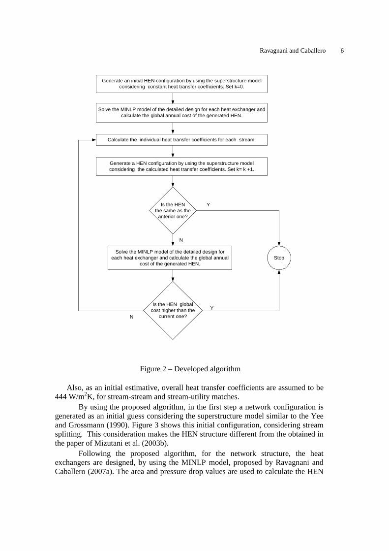
If the parameters of Mizutani et al. (2003b), are used in the present paper proposed methodology, i.e., considering no stream splitting and Ft = 1, assuming that all the heat exchangers have 1 shell, the results are very different. Table 12 shows the heat exchanges details for the best HEN obtained, presented in Figure 9. Obviously, the equipments have less area because of the neglected Ft calculus and because of the number of shells. It means that area and pressure drops will be smaller. All the equipments have one shell and the global cost (area and pressure drop) is lower than the obtained in Table 10. However, Table 10 presents more realistic results. Besides, they are in accordance with the standards of TEMA. A comparison with the results presented in Mizutani et al. (2003b) is shown in Table 13.

Optimal Heat Exchanger Network Synthesis Including the Heat Transfer Equipment Design 15
Table 10 – Equipment design for the Case 3 second structure
Global annual cost ($/year)
69,165.48
Area cost ($/year) 20,887.57 Pumping cost ($/year) 2,077.91 Utility cost ($/year) 46,200.00
E1 E2 E3 E4 E5 E6 Area (m2) 21.789 2873.56 1332.35 53.986 28.792 48.636 Q (kW) 430 3170 3600 1680 400 800
Ft 0.9966 0.805 .7759 .953 0.9936 0.9976 NS 1 4 2 1 1 1 Ntp 1 8 6 4 1 1
Ds (m) 0.438 1.320 1.320 0.635 0.489 0.635 Dotl (m) 0.406 1.270 1.270 0.594 0.457 0.594
Nt 112 1790 1826 370 148 250 Nb 5 14 8 3 4 3
dex (mm) 25.40 19.05 19.05 19.05 25.04 25.40 din (mm) 23.00 17.00 17.00 17.00 23.00 23.00 pt (mm) 31.75 25.40 25.04 25.04 31.75 31.75
hs (W/m2ºC) 833.866 521.208 1131.062 1183.621 1039.313 729.913 ht (W/m2ºC) 968.388 845.080 1072.545 1031.130 975.242 1116.333
L (m) 2.438 6.706 6.096 2.438 2.438 2.438 Uc (W/m2ºC) 366.369 272.635 426.365 425.690 402.515 363.836 Ud (W/m2ºC) 323.829 247.955 368.936 368.431 351.749 321.849
∆Pt (kPa) 490.642 25517.668 15159.264 2437.816 498.822 684.886 ∆Ps (kPa) 680.592 602.480 2211.578 662.634 639.001 500.040
rd (m2ºC/W) 3.59e-4 3.65e-4 3.65e-4 3.65e-4 3.59e-4 3.59e-4 arr square square square square square square
Hot fluid allocation tubes shell shell shell tubes tubes Pumping cost ($/year) 50.450 716.926 1054.109 79.585 48.955 127.883
Comments
For the first case studied, the final overall heat transfer coefficients considering fouling effects shows that the initial estimative (444.00 X 427.504 and 444.00 X 382.980) were not too bad. The HEN synthesized in the present paper is different from the obtained using the procedure of Mizutani et al. (2003b). It is because the authors use a non-stream splitting model for the HEN synthesis and a Ft correction factor equal to 1, in the MLDT calculus. When Ft is smaller than 1, areas are larger. Besides, the standards of the TEMA are not rigorously considered, for example, in the internal and external tubes diameter. The authors also did not publish all the details of the equipments as tube length, number of baffles and so one. Obviously, the Ft correction factor, the tube length and the inside and outside tube diameters as well as the tube arrangement and the fluids allocation are the responsible for these differences. In the second case studied, the number of heaters and coolers explain the large difference between the global annual costs. In the work of Mizutani et al. (2003b), the initial structure has 2 coolers and 1 heater, and the utility costs are the main responsible for the total cost. In the present paper, only 1 heater is considered in the

Ravagnani and Caballero 16
guess structure. As in the anterior case, the utility cost is the main responsible for the high global annual cost. It is important to comment, however, that if the Ft is assumed to be 1 the number of shells will be 1. It is not true in this example, as can be seen in heat exchangers E2 (4 shells) and E3 (2 shells) in the final HEN. It means that in these cases, the heat exchange area must by multiplied by 4 or 2, as well pressure drops, in each case. It is not considered in the paper of Mizutani et al. (2003b). It makes the area and pumping costs very different. The models were solved with GAMS, and the solvers SBB and DICOPT were used. The final results were obtained always in a less than 1000 seconds range, in a Pentium IV 1.7 GHz. The problem with the models, due to the high degree of complexity, is the dependence with the variables initialisation. Much time can be spent to adjust variables to obtain ideal upper and lower limits, to avoid local minima, very common in this kind of problems.
Conclusions In this paper an algorithm for the synthesis of HEN including the detailed design of the equipments is proposed. It is based in a decomposition method that includes a MINLP model for the optimal synthesis of HEN and a MINLP model for the optimal design of a shell and tube heat exchanger design, following rigorously the standards of TEMA. The global annual cost objective function takes in account investment, utility and pumping costs. An initial HEN configuration is synthesized by using constant heat transfer coefficients, considering the possibility of stream splitting and assuming isothermal mixing. The equipments are designed and the individual stream film coefficients are calculated. With these values, a new HEN configuration is generated and its structure is compared with the first one. If it is different, the HEN equipments are designed and the global annual cost is calculated. The new heat transfer coefficients are calculated and the objective function is tested. If it is smaller than the anterior one, the procedure must continue. If not, the procedure must stop and the HEN with the smallest global annual cost is assumed as the best one. Two examples were used to describe the algorithm applicability, comprising two different possibilities in the algorithm use. The final results obtained in this paper are more realistic than the presented in the literature, because of the TEMA standards, the use of Ft correction factor and the number of shells. In the second case, a big difference exists in the results obtained. The objective value is minor because of the large use of utilities in the solution presented in Mizutani et al. (2003b). The heat exchangers most important variables in manufacturing the equipment are available. Moreover, the designed heat exchangers are rigorously in accordance with the standards of the TEMA. Certainly the tube length, jointly with the number of tubes, the number of shells and the heat exchangers configurations are the responsible for the differences in the compared results.
Table 11 – Case 2 Global annual cost
Global annual cost ($/year) Initial guess (considering constant heat transfer coefficients)
60,537.87
Iteration 1 70,070.18 Iteration 2 69,165.48
Optimal Heat Exchanger Network Synthesis Including the Heat Transfer Equipment Design 17
The algorithm presents always the best HEN configuration considering stream splitting, assuming isothermal mixing. It presents also the detailed heat exchangers design, rigorously according the Standards of TEMA.
E1
H1
H2
H3
C1
C2
C3
423
363
454
398
373
288
360.167
317
283
293
293389
433
333
333
340.5
E2
E3
E4
E5
H1
(3600)
(800)
(3600)
(430)(770)
448.625 443
E6
(1200)(450)
353
Figure 9 – Case 2 best HEN configuration with no stream splitting
Table 12 – Equipment design for the Case 2 with no stream splitting and Ft =1
Global annual cost ($/year)
61,795.87
Area cost ($/year) 14,546.17 Pumping cost ($/year) 1,049.70 Utility cost ($/year) 46,200.00
E1 E2 E3 E4 E5 E6 Area (m2) 33.072 28.792 482.004 463.333 48.636 108.264 Q (kW) 430 450 3600 3600 800 1200 Ds (m) 0.533 0.489 1.067 1.118 0.635 0.838 Dotl (m) 0.489 0.457 1.022 1.073 0.594 0.796
Nt 170 148 1201 1848 170 348 Nb 4 4 31 21 6 3
dex (mm) 25.40 25.40 19.05 19.05 25.04 19.05 din (mm) 23.00 23.00 14.00 17.00 23.00 17.00 pt (mm) 31.75 31.75 25.04 25.04 31.75 25.04
hs (W/m2ºC) 952.348 711.250 925.368 825.081 1134.904 954.308 ht (W/m2ºC) 1207.505 927.190 1039.974 1038.511 1544.258 1154.139
L (m) 2.438 2.438 6.706 6.096 2.438 2.438 Uc (W/m2ºC) 424.903 334.770 354.023 369.228 503.966 756.005 Ud (W/m2ºC) 137.251 298.893 310.295 325.368 107.875 571.404
∆Pt (kPa) 823.566 443.111 1390.571 7048.236 1469.051 791.090 ∆Ps (kPa) 831.579 493.491 1677.972 813.836 633.456 419.525
rd (m2ºC/W) 5e-3 3.59e-4 3.98e-4 3.65e-4 0.007 3.65e-4 arr square square square square square square
Hot fluid allocation tubes shell tubes tubes shell tubes Pumping cost ($/year) 96.657 51.523 269.858 269.614 238.742 123.310

Ravagnani and Caballero 18
Table 13 – Case 2 final results Mizutani et al. (2003b) Present paper considering no
stream splitting and Ft = 1 Present paper
Total annual cost ($/year) 202,920 61,795.87 69,165.48 Area cost ($/year) 12,388 14,546.17 20,887.57
Pumping cost ($/year) 17,076 1,049.70 2,077.91 Utility cost ($/year) 153,456 46,200.00 46,200.00
Nomenclature A heat exchange area acost area cost constant arr tube arrangement a1, a2, a3 and a4 empirical coefficients for Equations 69 – 72 and 77 - 78 b1, b2, b3 and b4 empirical coefficients for Equations 73 – 76 and 79 - 80 ccost pumping cost constant Cp heat capacity dex tube outside diameter din tube inside diameter Dotl tube bundle diameter Ds shell external diameter Fc fraction of total tubes in cross-flow Fsbp fraction of cross-flow area available for bypass flow fls shell-side Fanning factor fl t tube -side Fanning factor Ft correction factor of LMTD hoi shell-side heat transfer coefficient for an ideal tube bank hs shell-side film coefficient ht tube-side film coefficient Jb correction factor for bundle-bypassing effects Jc correction factor for baffle configuration effects ji Colburn factor Jl correction factor for baffle-leakage effects L tube length lc baffles cut LMTD log mean temperature difference ls baffle spacing m mass flow rate Nb number of baffles Nc number of tube rows crossed in one cross-flow section Ncw number of tube columns effectively crossed in each window NS number of shells Nt number of tubes Ntp number of tube passes Nu number of Nusselt Pcost pumping cost
Optimal Heat Exchanger Network Synthesis Including the Heat Transfer Equipment Design 19
pn tube pitch normal to flow pp tube pitch parallel to flow Pr number of Prandtl pt tube pitch Q heat duty Re number of Reynolds Rb pressure drop correction factor for bundle-bypassing effects rd fouling factor Rl pressure drop correction factor for baffle-leakage effects Sm reference normal area for shell-side flow Ssb shell-to-baffle leakage area Stb tube-to-baffle leakage area for one baffle Sw area flow thought the window Swg gross window area Swt window area occupied by tubes T temperature Uc clean overall heat transfer coefficient Ud dirty overall heat transfer coefficient vt tube-side fluid velocity yarr binary variable which defines tube pattern arrangement ybwg binary variable which defines internal tube diameter ydex binary variable which defines external tube diameter yf binary variable which defines the fluid allocation yl binary variable which defines the tube length yls binary variable which defines the baffle spacing ynt binary variable which defines the variables of Table 1 yres binary variable which defines the shell-side Reynolds number yrearr binary variable which represents yres and yarr ε roughness ∆P pressure drop ∆Pbi shell-side pressure drop for ideal cross-flow ∆Pwi pressure drop for the window k thermal conductivity µ viscosity ρ density index: h hot fluid c cold fluid s shell-side t tube-side Acknowledgment The authors acknowledge financial support provided by CNPq (Brazilian National Council of Science and Technological Development) and to the Spanish “Ministerio de Educación y Ciencia” under project CTQ2005-05456.

Ravagnani and Caballero 20
References Athier, G., Floquet, P., Pibouleau L., et al. Optimization of Heat Exchanger Networks
by Coupled Simulated Annealing and NLP Procedures. Computers and Chemical Engineering, v. 20, Supplement 1, pp. S13 – S18, 1996.
Athier, G., Floquet, P., Pibouleau L., and Domenech, S., Synthesis of Heat Exchanger Networks by Simulated Annealing and NLP Procedures. AIChE Journal, 43, 3007, 1997.
Bjork, K. and Westerlund, T., Global Optimization fo Heat Exchanger Network Synthesis Problems With and Without the Isothermal Mixing Assumption, Computers and Chemical Engineering, 26, 1581-1593, 2002.
Blackwell, W. W. and Haydu, L., Calculating the Correct LMDT in Shell-and-Tube Heat Exchangers, Chemical Engineering, 101-106, August (1981).
Cerda, J. and Westerberg, A. W., Synthesizing heat exchanger networks having restricted stream/stream matches using transportation problem formulation, Chemical Engineering Science, 38, 1723, 1983.
Ciric, A. R. and Floudas, C. A., Heat Exchanger Network Synthesis withou Decomposition, Computers and Chemical Engineering, 15, 385-396, 1991.
Colberg, R. D. and Morari, M., Área and Capital Cost Targets for Heat Exchanger Network Synthesis with Constrained Matches and Unequal Heat Transfer Coefficients, Computers and Chemical Engineering, 14, 1, 1990.
Daichendt M. M. and Grossmann, I. E., A Preliminary Screening Procedure for MINLP Heat Exchanger Network Synthesis Using Agregated Models, Chemical Engineering Research and Design, 72, 357-363, 1994.
Duran, M. A. and Grossmann, I. E., Simultaneous Optimization and Heat Integration of Chemical Processes, AIChE Journal, 32, 592, 1986.
Floudas, C. A., Ciric, A. R. and Grossmann, I. E., Automatic Synthesis of Optimum Heat Exchanger Network Configurations, AIChE Journal, 32, 276, 1986.
Frausto-Hernández, S., Rico-Ramirez, V. Jiménez-Gutiérrez, A. and Hernández-Castro, S., MINLP Synthesis of Heat Exchanger Networks Considering Pressure Drop Effects, Computers and Chemical Engineering, 14, 1, 2003.
Furman, K. C. and Sahinidis, N. V., A Critical Review and Annotated Bibliography for Heat Exchanger Network Synthesis in the 20th Century, Ind. Eng. Chem. Res., 41, 2335-2370, 2002.
Grossmann, I. E., Caballero, J. A. and Yeomans, H., Advances in Mathematical Programming for the Synthesis of Process Systems, Latin American Applied Research, 30:263-284, 2000.
Grossmann, I. E., Yeomans, H. and Kravanja, Z., A Rigorous Disjunctive Optimization Model for Simultaneous Flowsheet Optimization and Heat Integration, Computers and Chemical Engineering, 22, S157-S164, 1998.
Gundersen, T. Duvold, S. and Hashemi-Ahmady, A., An Extended Vertical MILP Model for Heat Exchanger Network Synthesis, Computers and Chemical Engineering, 20, s97, 1996.
Gundersen, T. and Grossmann, I. E., Improved Optimization Strategies for Automated Heat Exchanger Network Synthesis through Physical Insights, Computers and Chemical Engineering, 14, 925, 1990.

Optimal Heat Exchanger Network Synthesis Including the Heat Transfer Equipment Design 21
Gundersen, T. and Naess, L., The synthesis of cost optimal heat exchanger networks – An insustrial review of the state of the art, Computers and Chemical Engineering, Vol. 12, n. 6, pp. 503-530, 1998.
Kern, D., Process Heat Transfer, McGraw-Hill: New York, 1950. Lee, S. and Grossmann, I. E., New Algorithms for Nonlinear Generalized Disjunctive
Programming, Computers and Chemical Engineering, v. 24, pp. 2125-2141, 2000.
Lewin, D. R.; Wang, H. and Shalev, O. A generalized method for HEN synthesis using stochastic optimization - I. General framework and MER optimal synthesis. Computers and Chemical Engineering, v. 22, pp. 1503 - 1513, 1998.
Lin, B. and Miller, D. C. Solving heat exchanger network synthesis problems with Tabu Search, Computers and Chemical Engineering, v. 22, pp. 1451 – 1464, 2004.
Linnhoff, B. and Flower, J. Synthesis of Heat Exchanger Networks: I Systematic Generation of Energy Optimal Networks, AIChE Journal, v. 24, n. 4, pp. 633 – 642, 1978.
Linnhoff, B. and Hindmarsh, E., The Pinch Design Method for Heat Exchanger Networks, Chemical Engineering Science, Vol. 38, pp. 745-763, 1983.
Linnhoff, B., Mason, D. R. and Wardle, I., Understanding Heat Exchanger Networks, Computers and Chemical Engineering, Vol. 3, pp. 295-302, 1979.
Linnhoff, B., Towsend, D. W., Boland, D., Hewitt, G. F., Thomas, B. E. A., Guy, A. R. and Marsland, R. H., A User Guide on Process Integration for the Efficient Use of Energy, The Institute Of Chemical Engineers, U.K., 1982.
Linnhoff, B., Pinch Analysis - A State-of-the-Art Overview, Transactions of the IChemE, Vol. 71, Part A, pp.503-522, September, 1993.
Linnhoff, B., Use Pinch Analysis to Knock Down Capital Costs and Emissions, Chemical Engineering Progress, pp. 32-57, August, 1994.
Mizutani, F. T., Pessoa, F. L. P., Queiroz, E. M., Hauan, S. and Grossmann, I. E., “ Mathematical Programming Model for Heat Exchanger Network Synthesis Including Detailed Heat Eschanger Designs. 1. Shell-and-Tube Heat Exchanger Design”, In. Eng. Chem. Res., 42, 4009-4018. (2003a).
Mizutani, F. T., Pessoa, F. L. P., Queiroz, E. M., Hauan, S. and Grossmann, I. E., “ Mathematical Programming Model for Heat Exchanger Network Synthesis Including Detailed Heat Eschanger Designs. 2. Network Synthesis”, In. Eng. Chem. Res., 42, 4019-4027. (2003b).
Nielsen, J. S., Hansen, M. W. e Joergensen, S., Heat Exchanger Network Modelling Framework for Optimal Design and Retrofitting, Computers and Chemical Engineering, 20, s249, 1996.
Panjeh Shahi, M. H., "Pressure Drop Consideration in Process Integration", Ph. D. Thesis - UMIST (1992).
Papalexandri, K. P. and Pistikopoulos, E. N., A Multiperiod MINLP Model for the Synthesis of Heat and Mass Exchange Networks, Computers and Chemical Engineering, 18, 12, 1125, 1994.
Papulias, S. A. and Grossmann, I. E., A structural optimization approach in process synthesis. Part II: Heat Recovery Networks, Computers and Chemical Engineering, 7, 707, 1983.

Ravagnani and Caballero 22
Polley, G. T., Panjeh Shahi, M. H. M., “Interfacing Heat Exchanger Network Synthesis and Detailed Heat Exchanger Design’, Trans. Inst. Chem. Eng., 69, 445-447. (1992)
Polley, G. T., Panjeh Shahi, M. H. M. and Jegede, F. O., “Pressure Drop Considerations in the Retrofit of Heat Exchanger Networks”, Trans. Inst. Chem. Eng., 68, 211-220. (1990)
Quesada, I. E. and Grossmann, I. E., Global Optimization Algorithm for Heat Exchanger Networks, Industrial Engineering Chemistry Research, 32, 487, 1993.
Raman, R. and Grossmann, I. E., Modeling and Computational Tecniques for Logic Based Integer Programming, Computers and Chemical Engineering, 18, 563-568, 1994.
Ravagnani, M. A. S. S., Silva, A. P. and Andrade, A. L. Detailed Equipment Design in Heat Exchanger Networks Synthesis and Optimization. Applied Thermal Analysis, v. 23, pp. 141 – 151, 2003.
Ravagnani, M. A. S. S. and Caballero, J. A., A MINLP Model for the Rigorous Design of Shell and Tube Heat Exchangers using the TEMA Standards, Chemical Engineering Research and Design, Paper to be published, 2007a.
Ravagnani, M. A. S. S. and Caballero, J. A., Optimal Heat Exchanger Network Synthesis with the Detailed Heat Transfer Equipment Design, Computers And Chemical Engineering, Paper to be published, 2007b.
Sorsak, A. and Kravanja, Z., Simultaneous MINLP synthesis of Heat Exchanger Networks Comprising Different Exchanger Types, Computers and Chemical Engineering v. 26, 8, pp. 599-615, 2002.
Smith, R., Chemical Process Design and Integration, Wiley (2005). Sorsak, A. and Kravanja, Z., MINLP retrofit of Heat Exchanger Networks Comprising
Different Exchanger Types, Computers and Chemical Engineering v. 28, 8, pp. 235-251, 2004.
Taborek, J., "Shell-and-Tube Heat Exchangers", Section 3.3, Heat Exchanger Design Handbook, Hemisphere Publishing (1983).
Turkay, M. and Grossmann, I. E., Logic-based MINLP Algorithms for the Optimal Synthesis of Process Networks. Computers and Chemical Engineering v. 20, 8, pp. 959-978, 1996.
Yee, T. F. and Grossmann, I. E., Simultaneous Optimization Models for Heat Integration, II: Heat Exchanger Network Synthesis, Computers and Chemical Engineering, 14, 1165, 1990.
Yu, H., Fang, H., Yao, P. and Yuan, Y. A combined genetic algorithm/simulated annealing algorithm for large scale system energy integration, Computers and Chemical Engineering v. 24, 8, pp. 1781-2039, 2000.
Zamora, J. and Grossmann, I. E., A Global Optimization Algorithm for the Synthesis of Heat Exchanger Networks with No Stream Splits, Computers and Chemical Engineering, 22, 367-384, 1998.
Zhu, X. X., Automated Design Method for Heat Exchanger Network Using Block Decomposition and Heuristic Rules, Computers and Chemical Engineering, 21, 1095, 1997.