Embed Size (px)
Citation preview

4th International Conference on Electrical and Computer EngineeringICECE 2006, 19-21 December 2006, Dhaka, Bangladesh
OPTIMAL DESIGN OF VOICE COIL MOTOR FORAPPLICATIONIN ACTIVE VIBRATION ISOLATION
Rahul Banik, Dong-Yeon Lee and Dae-Gab Gweon
NOM Lab, Dept. of Mech. Engg., KAIST373-1 Guseong dong, Yuseong-gu, Daejeon 305-701, South Korea
E-mail: rahulbanikgkaist.ac.kr
ABSTRACTVibration isolators typically reduce the vibrationtransmitted to the nano-precision measuringinstrument providing managed stiffness anddamping. Active isolators use feedback to provide thenecessary control signal. In this paper we propose anoptimized design of a Voice coil motor that can beused to implement a suitable controller for activeisolation to attenuate the low frequency vibration.
1. INTRODUCTIONPrecision measuring instruments such as AtomicForce Microscopes with resolution in nano-meterrange are always affected by ground borne vibrationsthat have typical amplitude in sub micrometer region.A vibration isolation system reduces the effect ofsuch disturbance to transmit to the instrument usuallyby using a spring damper system with very low cutoff frequency which works as a low pass filter for thedisturbance. A passive system can be designed toprovide the necessary attenuation to this vibration. Toeffectively attenuate the low frequency groundvibration, a hybrid active passive system isnecessary([I], [3]).
The passive system attenuates high frequencydisturbance with reasonable attenuation rate and thenthe active system works to attenuate the lowfrequency vibration effect. The active systemimplements active control using sensors andactuators. The actuator of active vibration isolatorcan be of several types: mechanical mechanisms,piezoelectric actuators, pneumatic springs,electromagnetic motors and electrical linear motor.This research proposes implementation of
actuator, a Voice Coil Motor (VCM) on such anactive vibration isolator which works to control thevibration typically in range from 0.1 to 100 Hz. TheVCM was designed and optimized to providenecessary feedback force to nullify vibration effect.Necessary cost function was evaluated depending onpassive isolation effect and system dynamics. Forcegeneration was calculated using magnetic flux
reluctance method. Optimized result was thenevaluated comparing with the simulation result.
2. DESIGN OF THE SYSTEMThe isolation system is composed of four elastomermounts to support upper plate with the instrument tobe isolated(around 150Kg) along with three verticaland three horizontal VCMs mounted such that theycan control all six rigid body modes using feedbacksignal from the accelerometers connected to theupper plate as shown in figure 1. Accelerometersmeasure transmitted vibration from ground to upperplate and sends feedback signal to the actuators.
Fig. 1: Complete system with actuators and sensorsThe passive system can be realized as stiffness in
parallel with damper and actuators thus work as forcegenerators that work in parallel to the passive system.The actuators were designed as shown below
_ ~~~~~YOKE
_M AGNET_MMAGNET MANETr
Fig. 2: (a)Vertical actuator and (b)Horizontal actuator
3. OPTIMIZATION OF VERTICALVCMIn order to optimize these VCMs, a cost functionneeds to be defined along with design parameters thatcan be varied to arrive at the desired optimizationvalue. Force requirement depends on passive systemdynamics as the actuators work against stiffness and
341
Authorized licensed use limited to: Korea Advanced Institute of Science and Technology. Downloaded on February 3, 2010 at 20:14 from IEEE Xplore. Restrictions apply.

damping of the passive elastomers to providenecessary dynamic force to attenuate vibration.
The complete system model with two inputs(control signal input, Fu(s) and vibration input, b(s))contributing to output variable, p(s) is as follows:([M]s2 + [C]s + [K])p(s) = [C]sb(s) + [K]b(s) + FT (s)
tp(s) F~(s)+ ([C]s+[K]) b(s) (1)
([M]s2 + [C]s + [K]) ([M]s2 + [C]s + [K])M, C and K are mass, damping and stiffness
matrix respectively.To find the dynamic force required in vertical
direction, we use single degree of freedom modelwith K and C being the vertical directional stiffnessand damping respectively as:
K = 8.6*105 N/m and C = 1.42*103 Ns/m
Fig. 3: Single DOF system with actuation force Ft.From figure 3 we get force requirement for the
vertical actuator as follows[2]:Ms2P(s) + Cs(P(s) - B(s)) + K(P(s) - B(s)) = F]
3FVCM = 3nBgli = 3Kti> Ms T(s)XB + CSXB (T(s) -1) + KXB (T(s) -1) = 3FVCM
where T(s) Transmissibility of passive system
P(s) Cs+K
B(s) Ms2 +Cs+KWhere K, = Force constant = n*B9 *1n = No. of coil turns, Bg =Flux density at the air gap
and 1 = effective length of coil.Since control bandwidth is 0.1-100.OHz, to find
maximum force requirement, 100 Hz frequency was
considered since at that particular frequencymaximum acceleration and velocity is transferred tothe upper plate considering peak to peak groundvibration displacement B(s) = 100 micro meter.Transmissibility of passive system also varies withfrequency and it can be calculated from passivesystem dynamics as plotted in figure 4 and the valueis T(s) = 0.0143 = -36.9dB
Fig. 4: Transmissibility of passive system (verticaldirection)
Maximum force requirement is:3FVCM = S2XB+CSXB(T -1)+KVB(T -1) >FVCM =-29.33N
The VCM has to produce less than or equal to themaximum force requirement F = 30 N. So the costfunction is:minimc(|req|3|FV) =>(||fS2XB+CVB(T_1)+K2B(T= minimize (88 - 3FVCM )To choose the constraints we decide that the
designed actuator should have compact size alongwith maximum allowable temperature, saturated fluxdensity and maximum current through the coil as
constraints. The list is as follows:Table 1 : Cost function and constraints
COST(\
FUNCTION minimize (88-3FvcM)CONSTRAINTS
In order to optimize size of VCM, some geometricparameters are considered constant and the others are
varied at some defined range with the objective tominimize the cost function. Considering symmetrichalf part of the VCM, the geometric parameters are as
shown below:
Fig. 5: Symmetric half structure with geometricparameters.
Table 2: The fixed geometric parametersFixed constraints ValueLy (Magnet length) 40.0 mmTc (Coil thickness) 2.0mmWc (Coil width) 0.5*Wm
Way (Width of side air gap) 0.1*WmTcy (central yoke thickness) 2*TuyTch (Coil holder width) 2.00mmLc (Coil side length) 49.0mmLcc (Coil opposite side length) 14.00mmLce (Coil effective unit length) 2*((Lc-Tc)+(Lcc-Tc))
Table 3 shows the design variables with their range.
Table 3 : Design VariablesDesign Variables Design range
Tm (Magnet thickness) 2.0 - 5.0 mmWm (Magnet width) 10.0 - 25.0 mmTuy (Yoke thickness) 1.0- 5.0 mmi|Tg (Air gap thickness) 5.0 - 6.0 mmdc (coil diameter) 0.1- 1.0 mmIc (coil current) 0.3 - 1.0 Amp
342
<70 (C)Temperature (T)VCM size <40(mm)X47(mm)(Height x Length x width) x 46(mm)
Generated force (N) < 30NSaturated Flux density < 1.8T(Bs)Coil Current (I) .< 1 .0 Amp.
Authorized licensed use limited to: Korea Advanced Institute of Science and Technology. Downloaded on February 3, 2010 at 20:14 from IEEE Xplore. Restrictions apply.
Geometric constraints:Ly = 40 mm [combined length]
14 < Ty < 47 [combined thickness]
18 < Wy < 46 [combined width]Sog(1) =2IW +WL +2Wy < 46nin1>g(1) = 27 +1.22W <46n
and g(2) =2(W +T7m +I)+2IT <47> g(2) =4T,+2(7 +7Tg) <47nCurrent constraint:Current is considered to be less than or equal to1.OAmp to reduce the effect of electrical dynamics(i.e. effect of coil resistance and inductance)
Ic <1g(3):Ic -1.0<0
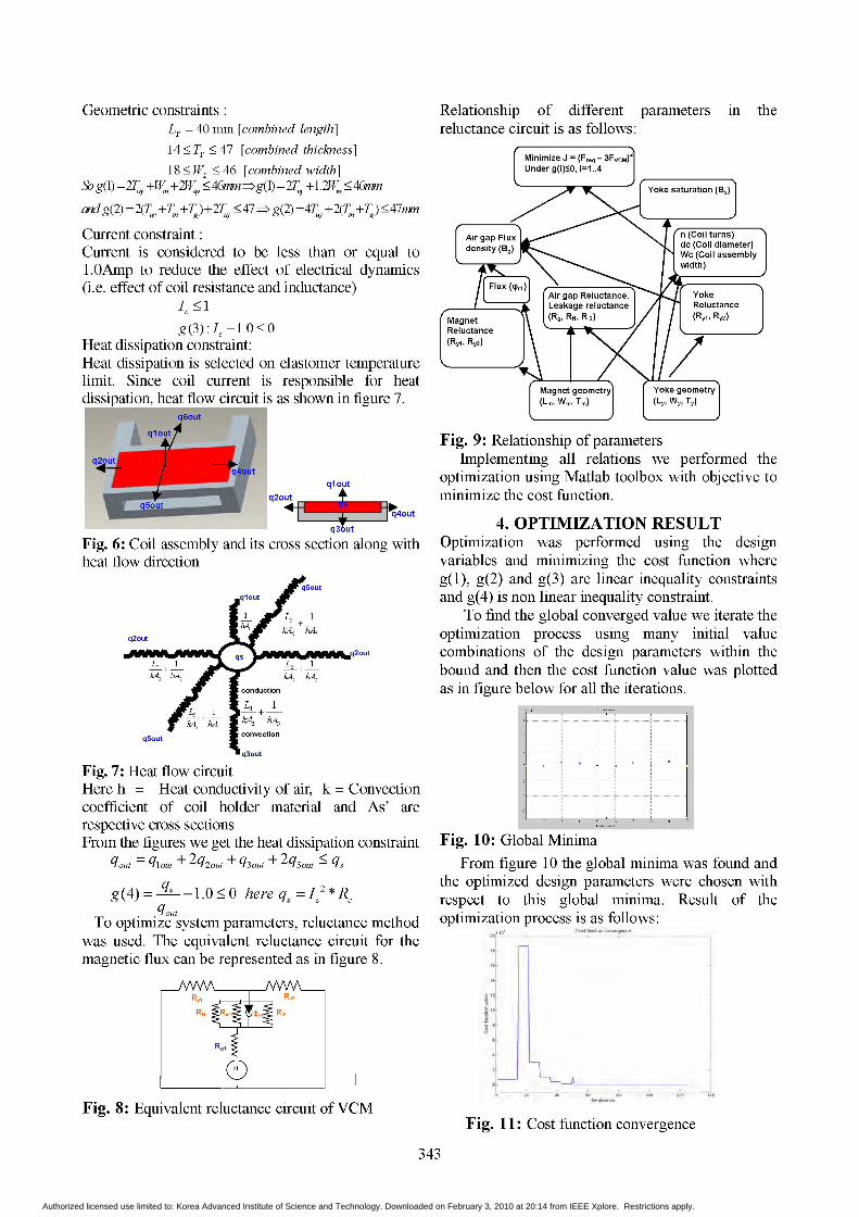
Heat dissipation constraint:Heat dissipation is selected on elastomer temperaturelimit. Since coil current is responsible for heatdissipation, heat flow circuit is as shown in figure 7.
..................,...,,...._.
-.............g.......................l._
.............................................
-qou|tqloutq20ut
q30ut q 2c4 u
Fig. 6: Coil assembly and its cross section along withheat flow direction
Fig. 7: Heat flow circuitHere h = Heat conductivity of air, k = Convectioncoefficient of coil holder material and As' arerespective cross sectionsFrom the figures we get the heat dissipation constraint
qout = qlout + 2q2out + q3out + 2q5out ' qs
g(4)= s -1.0<0 here qs =I2*R,qout
To optimize system parameters, reluctance methodwas used. The equivalent reluctance circuit for themagnetic flux can be represented as in figure 8.
Fig. 8: Equivalent reluctance circuit ofVCM
Relationship of different parameters in thereluctance circuit is as follows:
Fig. 9: Relationship of parametersImplementing all relations we performed the
optimization using Matlab toolbox with objective tominimize the cost function.
4. OPTIMIZATION RESULTOptimization was performed using the designvariables and minimizing the cost function whereg(1), g(2) and g(3) are linear inequality constraintsand g(4) is non linear inequality constraint.
To find the global converged value we iterate theoptimization process using many initial valuecombinations of the design parameters within thebound and then the cost function value was plottedas in figure below for all the iterations.
Fig. 10: Global MinimaFrom figure 10 the global minima was found and
the optimized design parameters were chosen withrespect to this global minima. Result of theoptimization process is as follows:
Fig. 11: Cost function convergence
343
Authorized licensed use limited to: Korea Advanced Institute of Science and Technology. Downloaded on February 3, 2010 at 20:14 from IEEE Xplore. Restrictions apply.

Figure 11 shows the cost function convergenceand the design variable convergence are shownbelow in figure 12
the result. The simulation model and result is asfollows:
Fig. 13: VCM model and flux distribution in thecross section.
Flux density distribution at the air gap is as follows:Flux densi at air gap
Fig. 14: Flux density distribution at air gapThe simulation result is shown in table 5Table 5:Comparison of Optimization and simulationParameter Value -Percent error from optimization resultN (No. of turns) 800 3.625Force 13.5 N -8.59Flux Density 10.47 T -4.25
From table 5 we see that simulation resultconforms to the optimization result.
The horizontal VCM can also be optimized in asimilar manner considering different parameters forthe horizontal isolation.
6. CONCLUSION
Fig. 12: Convergence of design variablesThe converged values are summarized in table 4.
Table 4: Optimization resultDesign Variables Design value after optimizationTm (Magnet thickness) 4.2617 mm = 4.25 mmWm (Magnet width) 24.5851 mm = 24.6 mmTuy (Yoke thickness) 4.9527 mm = 4.95mmTg (Air gap thickness) 5.1207 mm = 5.1 mmdc (coil diameter) 0.19 mmIc (Coil current') 0.9592 Amp. =0.96 Amp
Parameter ValueN (No. of turns) 770.84Force 14.6644 NFlux Density 0.49 T
Cost Function value 1.66e-10.
Force generated is FVCM = 2*Force = 29.12 N andFlux density is also within saturation limit (>1.8T).
5. SIMULATION
To verify the optimization result we perform FEMsimulation using Maxwell software and compared
The optimized design of a Voice Coil Motor wasperformed which can be used as an actuator for theActive Vibration Isolation system. The result of theoptimization was verified using FEM simulation.This optimized VCM can easily be implemented tocontrol the low frequency vibration typically withinthe range 0.1 to 100 Hz.
7. REFERENCE[1] Yi-De Chen, Chyun-Chau Fuh and Pi-Cheng Tung,
"Application of Voice Coil Motors in Active DynamicVibration Absorbers" , IEEE TRANSACTIONS ONM\AGNETICS, vol. 41, no. 3 pp. 1140-1154, March2005
[2] Duane C. Hanselman, "Brushless Permanent-MagnetMotor Design", McGraw-Hill, Inc. 1994
[3] Eric Flint, Patrick Flannery, Michael Evert and EricAnderson "Cryocooler Disturbance Reduction withSingle and Multiple Axis Active/Passive VibrationControl Systems" , Proceedings of the SPIEconference#3989, Paper#64, Newport Beach,CA, USA.
344
Authorized licensed use limited to: Korea Advanced Institute of Science and Technology. Downloaded on February 3, 2010 at 20:14 from IEEE Xplore. Restrictions apply.