Embed Size (px)
Citation preview
20th International Conference on Adaptive Structures and Technologies
October 20-22, 2009, Hong Kong
Dielectric Electro-Active Polymers in Active Vibration Isolation
R. Sarban1*, B. R. Mace2, E. Rustighi2 and R.W. Jones3
1* Danfoss PolyPower A/S, Nordborg, Denmark. 2 ISVR, University of Southampton, Southampton, U.K.
3University of Southern Denmark, SØnderborg, Denmark.
ABSTRACT
Physicists and chemists have long sought to develop lightweight materials that grow or shrink significantly in length or volume when subjected to electric stimulation. A new material of this type is Dielectric Electro-Active Polymer (DEAP), which when utilised as an actuator, has the potential to be an effective replacement for many conventional actuators. Of the range of DEAP-based actuators, that have been developed, those having a cylindrical configuration are among the most promising. Active vibration control applications of this technology have enormous potential with the tubular actuator possibly being used to damp vibrations, or for vibration isolation purposes where a sensitive device is protected from a vibration source. This contribution investigates the active vibration isolation performance of a core-free rolled tubular DEAP actuator which has been designed and developed by Danfoss PolyPower A/S. The static and dynamic characteristics of the tubular actuator are presented where the later is compared to highlight the dominant dynamic characteristics of the core-free tubular actuator. The tubular actuator is then used to provide active vibration isolation (AVI) of a 250 g mass subject to shaker generated ‘ground vibration’. An adaptive feedforward control approach is used to achieve this. The tubular actuator is shown to provide excellent isolation against harmonic vibratory disturbances with attenuation of 5 Hz and 10 Hz harmonics being 67 dB and 24 dB respectively. AVI against a narrow band vibratory disturbance with frequency content 2 – 8 Hz, provided an attenuation of 19 dB across the frequency band.
Keywords: Dielectric Electro-active Polymer, Tubular actuator, Vibration isolation, Feedforward adaptive vibration control.
INTRODUCTION
For decades scientists and engineers have sought to find an artificial equivalent of muscle to help in the development of new transducer technology. This is because muscles, simply by changing their length in response to nerve stimulation, can exert controlled amounts of force. In this search for an artificial equivalent of muscle, dielectric electro-active polymers (DEAP) have gained considerable attention because of their ability to undergo large deformation, their high energy density and
* Corresponding author: Tel: +45 7488 6285; Fax: +45 7488 6999; E-mail: [email protected]
relatively fast response [6, 7]. The basic structure of a DEAP comprises an elastomer film sandwiched between two electrodes. In actuator mode the applied electrical energy is converted into mechanical energy - the force of attraction between the electrodes squeezing the incompressible soft polymer film thereby causing an increase in area and decrease in thickness of the film. Of the range of DEAP actuators that have been developed those having a cylindrical configuration are among the most promising. Active vibration control (AVC) applications will be prominent with the tubular actuator being used to damp incoming vibrations between the vibration source and a fixed surface, or perhaps for vibration isolation purposes where a sensitive device is protected from a vibration source. Danfoss PolyPower A/S, have developed a core free tubular actuator with no pre-strain. Instead of trying to exploit the high strain performance provided by pre-strained acrylic DEAP the silicone-based tubular actuators are currently restricted to small strains (<3%), but is very durable against both mechanical and electrical breakdown due to the use of compliant metal electrodes and the limitation on the maximum strain. Lifetime testing of these devices has achieved over millions of cycles before a significant reduction in actuator performance has been recorded. This contribution reviews the static and dynamic characteristics and active vibration isolation performance of a core-free rolled tubular DEAP actuator (production serial Nr. 1093). The main characteristics of the DEAP material, called PolyPowerTM, are initially described. The dynamic characteristic of the tubular actuator is then presented. The dynamic characteristics provide an indication of the frequency range where active vibration isolation could be successful. The tubular actuator will then be used to isolate a 250 g mass from ‘ground vibration’, provided by an electrodynamic shaker, by using a feedforward active vibration control strategy. Initially isolation against periodic vibration is addressed. Two different types of controller, a single tone controller and a two tones controller are used to provide tonal isolation. Isolation against a narrowband vibration signal is then addressed with a FIR filter-based feedforward controller being used to achieve this. The controllers’ parameters are identified using a least mean squares (LMS) algorithm.
THE DEAP TUBULAR ACTUATOR
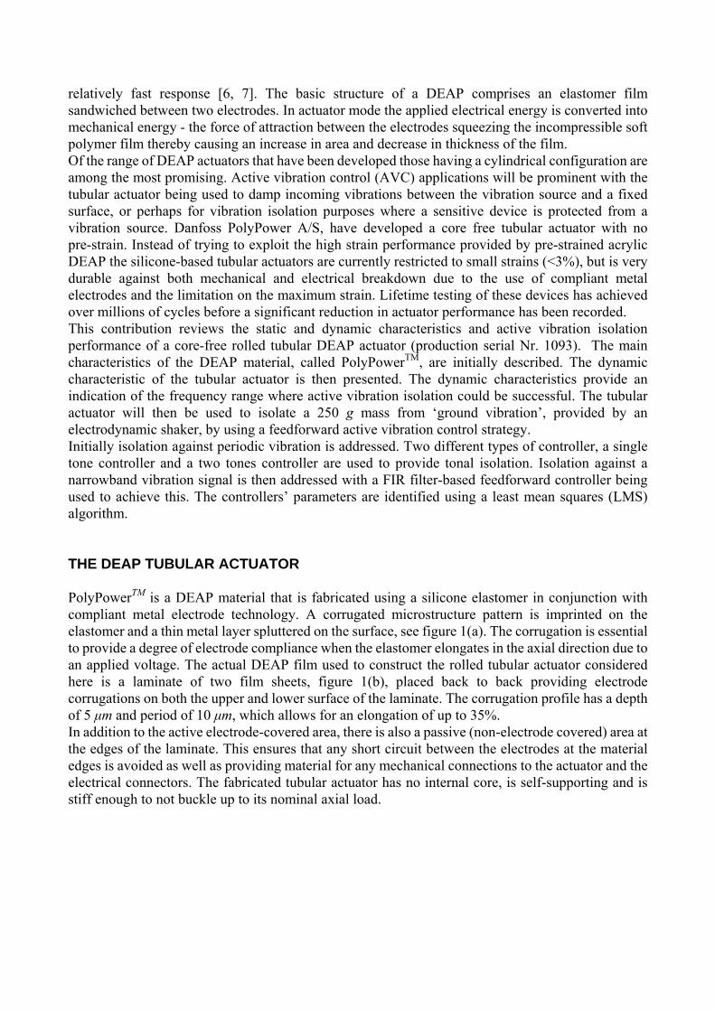
PolyPowerTM is a DEAP material that is fabricated using a silicone elastomer in conjunction with compliant metal electrode technology. A corrugated microstructure pattern is imprinted on the elastomer and a thin metal layer spluttered on the surface, see figure 1(a). The corrugation is essential to provide a degree of electrode compliance when the elastomer elongates in the axial direction due to an applied voltage. The actual DEAP film used to construct the rolled tubular actuator considered here is a laminate of two film sheets, figure 1(b), placed back to back providing electrode corrugations on both the upper and lower surface of the laminate. The corrugation profile has a depth of 5 μm and period of 10 μm, which allows for an elongation of up to 35%. In addition to the active electrode-covered area, there is also a passive (non-electrode covered) area at the edges of the laminate. This ensures that any short circuit between the electrodes at the material edges is avoided as well as providing material for any mechanical connections to the actuator and the electrical connectors. The fabricated tubular actuator has no internal core, is self-supporting and is stiff enough to not buckle up to its nominal axial load.
(a) (b) Figure 1. (a) DEAP sheet with corrugated silver electrodes. Electrode thickness, h = 100 nm. Thickness, H of the elastomer film = 40 μm (b) schematic illustrating the elongation of a laminate of two dielectric elastomer sheets
with complaint metal electrodes.
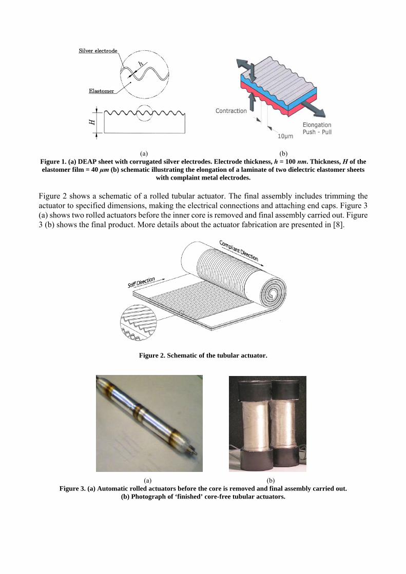
Figure 2 shows a schematic of a rolled tubular actuator. The final assembly includes trimming the actuator to specified dimensions, making the electrical connections and attaching end caps. Figure 3 (a) shows two rolled actuators before the inner core is removed and final assembly carried out. Figure 3 (b) shows the final product. More details about the actuator fabrication are presented in [8].
Figure 2. Schematic of the tubular actuator.
(a) (b)
Figure 3. (a) Automatic rolled actuators before the core is removed and final assembly carried out. (b) Photograph of ‘finished’ core-free tubular actuators.
CHARACTERISITICS OF THE TUBULAR ACTUATOR
DEAP tubular actuators are electromechanical devices with the actuation principle being based upon
the electrostatic pressure induced by a voltage potential between the electrodes. The attraction of the electrode reduces the thickness of the incompressible DEAP material thereby causing the actuator to elongate axially in the complaint direction, see figure 1(b). In this section both the static and dynamic behaviour of the actuator is introduced. The static behaviour provides insight into the range of operation while the dynamic characteristics provide insight in the speed of operation and an indication of the frequency range(s) where active vibration isolation might be successful.
Static response of the actuator
In the axial direction the mechanical stresses on a loaded and operating, tubular actuator satisfy the following stress balance:
M E LP P P= + (1)
where MP represents the electro-static stress, also referred to as the Maxwell pressure, EP represents the elastic stress induced in the actuator by the electro-static stress while LP represents the stress due to any external loading on the actuator. The Maxwell pressure is given as [9]:
2
0MVP r t
ε ε ⎛ ⎞= ⎜ ⎟⎝ ⎠
(2)
where 0ε and rε represent the absolute and relative dielectric constants of the DEAP material, V is the voltage potential between the electrodes and t the thickness of the laminated DEAP material, i.e. the distance between the electrodes. The elastic stress induced in the actuator can be expressed as a modified Mooney-Rivlin equation [8, 10]. ( ) ( )2 2
1 22EP C C h α α −= + ⋅ ⋅ − (3) where 1C and 2C are the DEAP’s material constants, h is an hardening factor related to the thickness and material properties of the metallic electrodes, and 0/L Lα = where L and 0L are the length and initial compliant lengths of the DEAP material in the actuator. The loading stress, caused by an applied loading force can be expressed as:
LL
FPw t
=⋅
(4)
Where FL is the load force and w the longitudinal length of the laminate sheet. Since the silicone-based DEAP is incompressible, its volume is conserved when a voltage is applied: 0 0 0L w t Lwt= (5) Due to the corrugated metallic electrodes the laminate sheet is constrained in the w direction,
allowing a simple relationship between the initial and current thickness of the laminate to be defined in terms of α:
0 0 00 0
L t tL t Lt tL α
= → = = (6)
Substituting (2), (3) and (4) into (1) and using (6) to represent t in terms of the initial laminate thickness, t0, gives:
( ) ( )2
2 2 20 1 2
0 0
2 Lr
FV C C ht w t
ε ε α α α α−⎛ ⎞= + ⋅ ⋅ − +⎜ ⎟ ⋅⎝ ⎠
(7)
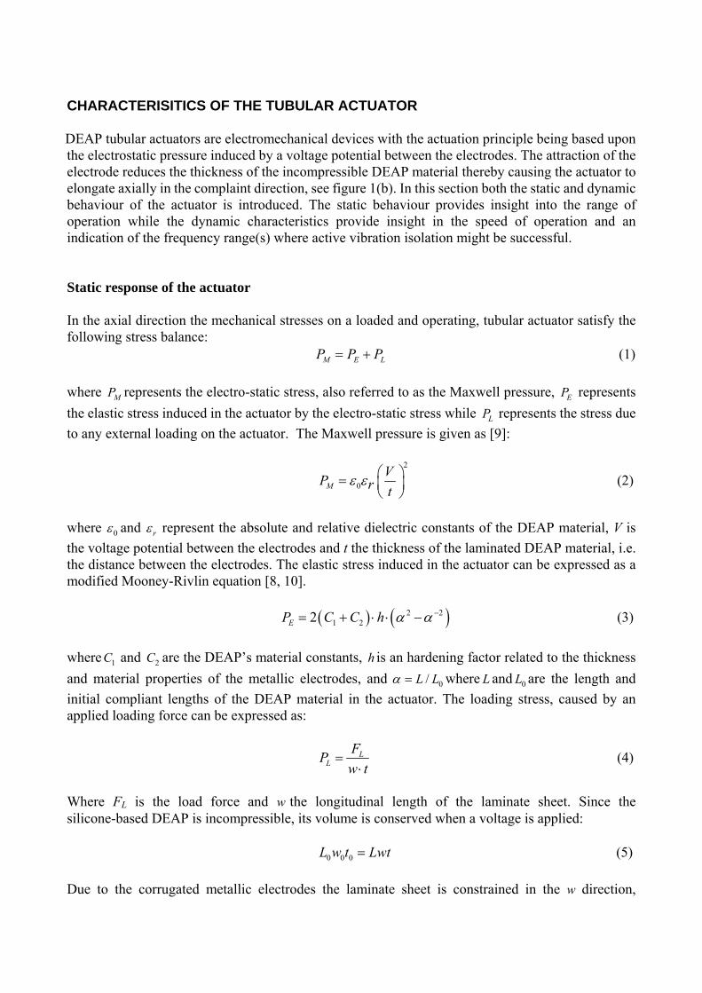
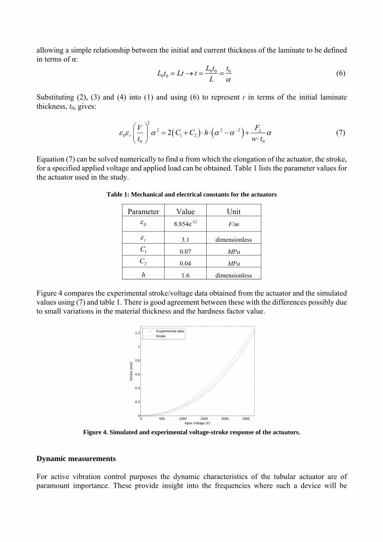
Equation (7) can be solved numerically to find α from which the elongation of the actuator, the stroke, for a specified applied voltage and applied load can be obtained. Table 1 lists the parameter values for the actuator used in the study.
Table 1: Mechanical and electrical constants for the actuators
Parameter Value Unit 0ε 8.854e-12 F/m
rε 3.1 dimensionless
1C 0.07 MPa
2C 0.04 MPa
h 1.6 dimensionless Figure 4 compares the experimental stroke/voltage data obtained from the actuator and the simulated values using (7) and table 1. There is good agreement between these with the differences possibly due to small variations in the material thickness and the hardness factor value.
0 500 1000 1500 2000 25000
0.2
0.4
0.6
0.8
1
1.2
Input Voltage (V)
Stro
ke (m
m)
Experimental dataModel
Figure 4. Simulated and experimental voltage-stroke response of the actuators.
Dynamic measurements
For active vibration control purposes the dynamic characteristics of the tubular actuator are of paramount importance. These provide insight into the frequencies where such a device will be
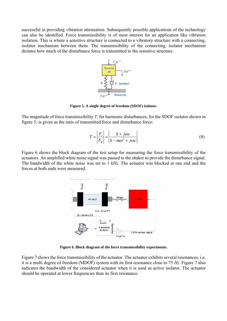
successful in providing vibration attenuation. Subsequently possible applications of the technology can also be identified. Force transmissibility is of most interest for an application like vibration isolation. This is where a sensitive structure is connected to a vibratory structure with a connecting, isolator mechanism between them. The transmissibility of the connecting, isolator mechanism dictates how much of the disturbance force is transmitted to the sensitive structure.
Figure 5. A single degree of freedom (SDOF) isolator. The magnitude of force transmissibility T, for harmonic disturbances, for the SDOF isolator shown in figure 5, is given as the ratio of transmitted force and disturbance force:
2tF k j cT
F k m j ce
ωω ω+
= =− +
(8)
Figure 6 shows the block diagram of the test setup for measuring the force transmissibility of the actuators. An amplified white noise signal was passed to the shaker to provide the disturbance signal. The bandwidth of the white noise was set to 1 kHz. The actuator was blocked at one end and the forces at both ends were measured.
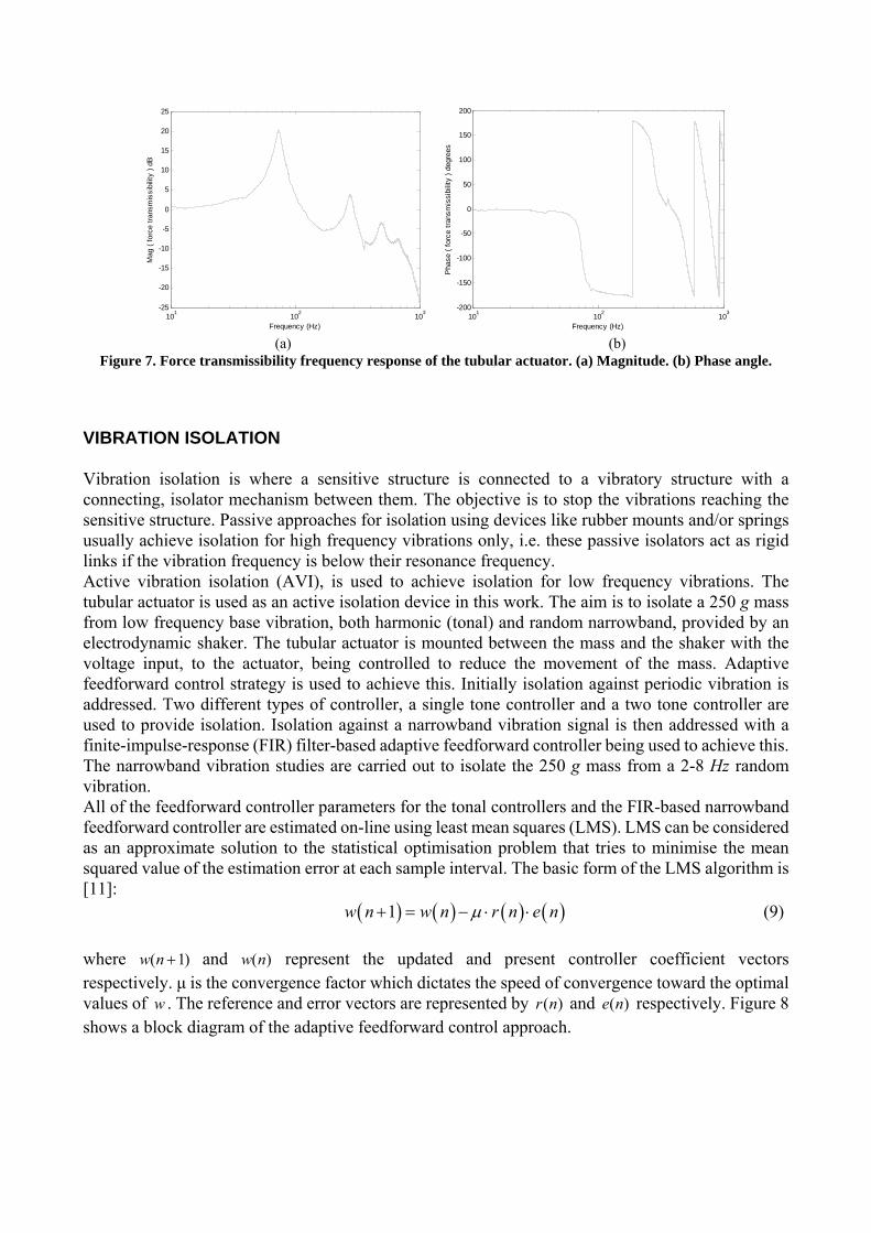
Figure 6. Block diagram of the force transmissibility experiments. Figure 7 shows the force transmissibility of the actuator. The actuator exhibits several resonances, i.e. it is a multi degree of freedom (MDOF) system with its first resonance close to 75 Hz. Figure 7 also indicates the bandwidth of the considered actuator when it is used as active isolator. The actuator should be operated at lower frequencies than its first resonance.
101 102 103-25
-20
-15
-10
-5
0
5
10
15
20
25
Frequency (Hz)
Mag
( fo
rce
trans
mis
sibi
lity
) dB
10
110
210
3-200
-150
-100
-50
0
50
100
150
200
Frequency (Hz)
Pha
se (
forc
e tra
nsm
issi
bilit
y ) d
egre
es
(a) (b)
Figure 7. Force transmissibility frequency response of the tubular actuator. (a) Magnitude. (b) Phase angle.
VIBRATION ISOLATION
Vibration isolation is where a sensitive structure is connected to a vibratory structure with a connecting, isolator mechanism between them. The objective is to stop the vibrations reaching the sensitive structure. Passive approaches for isolation using devices like rubber mounts and/or springs usually achieve isolation for high frequency vibrations only, i.e. these passive isolators act as rigid links if the vibration frequency is below their resonance frequency. Active vibration isolation (AVI), is used to achieve isolation for low frequency vibrations. The tubular actuator is used as an active isolation device in this work. The aim is to isolate a 250 g mass from low frequency base vibration, both harmonic (tonal) and random narrowband, provided by an electrodynamic shaker. The tubular actuator is mounted between the mass and the shaker with the voltage input, to the actuator, being controlled to reduce the movement of the mass. Adaptive feedforward control strategy is used to achieve this. Initially isolation against periodic vibration is addressed. Two different types of controller, a single tone controller and a two tone controller are used to provide isolation. Isolation against a narrowband vibration signal is then addressed with a finite-impulse-response (FIR) filter-based adaptive feedforward controller being used to achieve this. The narrowband vibration studies are carried out to isolate the 250 g mass from a 2-8 Hz random vibration. All of the feedforward controller parameters for the tonal controllers and the FIR-based narrowband feedforward controller are estimated on-line using least mean squares (LMS). LMS can be considered as an approximate solution to the statistical optimisation problem that tries to minimise the mean squared value of the estimation error at each sample interval. The basic form of the LMS algorithm is [11]:
( ) ( ) ( ) ( )1w n w n r n e nμ+ = − ⋅ ⋅ (9)
where ( 1)w n + and ( )w n represent the updated and present controller coefficient vectors respectively. μ is the convergence factor which dictates the speed of convergence toward the optimal values of w . The reference and error vectors are represented by ( )r n and ( )e n respectively. Figure 8 shows a block diagram of the adaptive feedforward control approach.
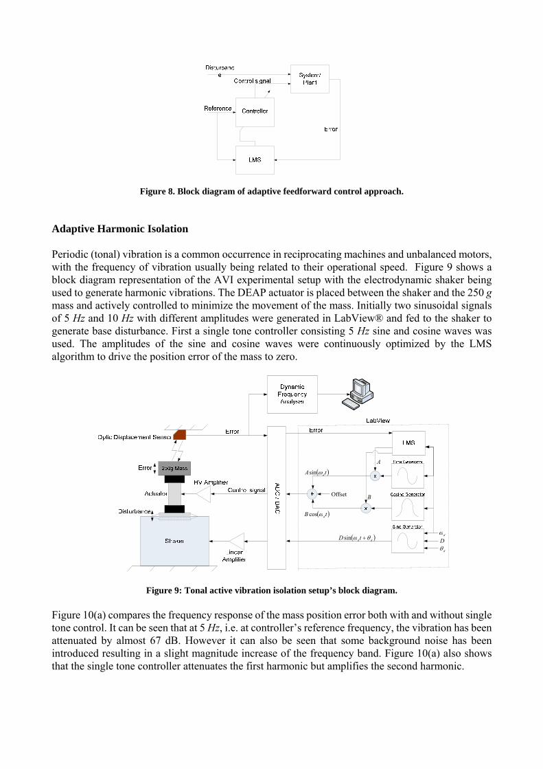
Figure 8. Block diagram of adaptive feedforward control approach.
Adaptive Harmonic Isolation
Periodic (tonal) vibration is a common occurrence in reciprocating machines and unbalanced motors, with the frequency of vibration usually being related to their operational speed. Figure 9 shows a block diagram representation of the AVI experimental setup with the electrodynamic shaker being used to generate harmonic vibrations. The DEAP actuator is placed between the shaker and the 250 g mass and actively controlled to minimize the movement of the mass. Initially two sinusoidal signals of 5 Hz and 10 Hz with different amplitudes were generated in LabView® and fed to the shaker to generate base disturbance. First a single tone controller consisting 5 Hz sine and cosine waves was used. The amplitudes of the sine and cosine waves were continuously optimized by the LMS algorithm to drive the position error of the mass to zero.
dθ
dω
A
B
( )tA dωsin
( )tB dωcos
( )dd tD θω +sin
Offset
D
Figure 9: Tonal active vibration isolation setup’s block diagram. Figure 10(a) compares the frequency response of the mass position error both with and without single tone control. It can be seen that at 5 Hz, i.e. at controller’s reference frequency, the vibration has been attenuated by almost 67 dB. However it can also be seen that some background noise has been introduced resulting in a slight magnitude increase of the frequency band. Figure 10(a) also shows that the single tone controller attenuates the first harmonic but amplifies the second harmonic.

0 2 4 6 8 10 12 14 16 18 20
-90
-80
-70
-60
-50
-40
-30
-20
-10
0
X: 5Y: -6.232
X: 5Y: -73.14
Frequency (Hz)
Mag
(mm
) dB
No ControlSingle Tone Control
0 2 4 6 8 10 12 14 16 18 20
-90
-80
-70
-60
-50
-40
-30
-20
-10
0
X: 10Y: -51.59
Frequency (Hz)
X: 5Y: -6.232
Mag
(mm
) dB
No ControlTwo Tone Control
(a) (b)
Figure 10: Control of harmonic vibrations. (a) single tone control (b) two tone control
In order to deal with the multiple harmonics, depending on the frequency range where isolation is required, a number of tone controllers might be required. In order to attenuate both 5 Hz and 10 Hz disturbance a two tone controller is required. The concept of the two tone controller is the same as the single tone controller shown in figure 9 except there are now two targeted frequencies; 5 Hz and 10 Hz. Two pairs of sine/cosine waves were generated at these frequencies and fed to the actuator. All four amplitudes, of sine/cosine pairs, were adapted by LMS and summed before being sent to the high voltage amplifier which supplies the signal to the tubular actuator. Figure 10(b) shows the frequency response of the error attenuation using the two tone controller. It can be seen that the contribution of the second tone is reduced by 24 dB compared to previous case.
0 0.1 0.2 0.3 0.4 0.5 0.6 0.7 0.8 0.9 1-0.5
-0.4
-0.3
-0.2
-0.1
0
0.1
0.2
0.3
0.4
0.5
Time (sec)
Erro
r (m
m)
No ControlSingle Tone ControlTwo Tone Control
0 5 10 15 20 25 30 35 40 45 50
-1
-0.8
-0.6
-0.4
-0.2
0
0.2
0.4
0.6
0.8
1
Time (sec)
Erro
r (m
m)
Controller OFF Controller ON
(a) (b)
Figure 11. Time response performance of adaptive harmonic isolation. (a) steady-state time response (b) tonal controller convergence.
Figure 11(a) compares the time responses of ‘no’ control, ‘single tone’ control and ‘two tone’ control. The comparisons are carried out after the controller parameters have converged. It can be seen that in the single tone control the error is dominated by a 10 Hz tone, whereas in the two tone control the effect of the 10 Hz tone is significantly reduced. Figure 11(b) shows the time response of the mass position error showing that good convergence of the tonal controller takes place within 5 seconds. The convergence factor μ used in these experiments was less than half of the value required to drive the LMS algorithm unstable so it is possible to further improve the rate of convergence by increasing μ.
Adaptive Narrowband Isolation
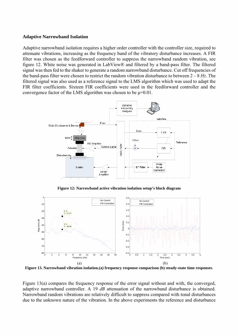
Adaptive narrowband isolation requires a higher order controller with the controller size, required to attenuate vibrations, increasing as the frequency band of the vibratory disturbance increases. A FIR filter was chosen as the feedforward controller to suppress the narrowband random vibration, see figure 12. White noise was generated in LabView® and filtered by a band-pass filter. The filtered signal was then fed to the shaker to generate a random narrowband disturbance. Cut off frequencies of the band-pass filter were chosen to restrict the random vibration disturbance to between 2 – 8 Hz. The filtered signal was also used as a reference signal to the LMS algorithm which was used to adapt the FIR filter coefficients. Sixteen FIR coefficients were used in the feedforward controller and the convergence factor of the LMS algorithm was chosen to be μ=0.01.
Offset
Figure 12: Narrowband active vibration isolation setup’s block diagram
0 2 4 6 8 10 12 14 16 18 20-80
-70
-60
-50
-40
-30
-20
-10
0
X: 5Y: -27.27
X: 5Y: -45.98
Frequency (Hz)
Mag
(mm
) dB
No ControlFIR Controlled
0 0.5 1 1.5 2 2.5 3 3.5 4 4.5 5
-0.4
-0.3
-0.2
-0.1
0
0.1
0.2
0.3
0.4
0.5
Time (sec)
Erro
r (m
m)
No ControlFIR Controlled
(a) (b)
Figure 13. Narrowband vibration isolation.(a) frequency response comparison (b) steady-state time responses. Figure 13(a) compares the frequency response of the error signal without and with, the converged, adaptive narrowband controller. A 19 dB attenuation of the narrowband disturbance is obtained. Narrowband random vibrations are relatively difficult to suppress compared with tonal disturbances due to the unknown nature of the vibration. In the above experiments the reference and disturbance
signals were in perfect coherence and therefore relatively good attenuation has been achieved. In many applications, the disturbance and reference signals will not be very coherent which might reduce the anticipated AVI performance. CONCLUSIONS
This contribution introduces the static and dynamic characteristics and the active vibration isolation performance of a core-free tubular dielectric electro-active polymer actuator. The tubular actuator used here has multiple-degree of freedom characteristics with a first resonant frequency of approximately 75 Hz. This indicates that its general use for active vibration control and in this work their specific use for active vibration isolation should be restricted to frequencies up to at most ≈ 30 Hz, just less then half of the first resonant frequency. A tubular actuator was then used to isolate a 250 g mass from lower frequency ‘ground vibration’, provided by an electrodynamic shaker. A number of active vibration isolation studies were successful. Low frequency vibratory disturbances, both harmonic and random narrowband were used in these studies. The adaptive single tone and two tone controllers provided large attenuations of the disturbance signals – the two tone controller providing a peak attenuation of 45 dB. The attenuation of the narrowband random disturbances, achieved using a 16 coefficient adaptive FIR-based feedforward controller, were comparably less successful providing 19 dB across the isolation frequency range of interest. Future work will concentrate on examining the isolation performance of the tubular actuator for wider band low frequency random disturbances. Much higher order FIR-based controllers will be required to achieve this and the possibility of using adaptive IIR filters, to reduce the number of estimated parameters will be examined. In addition the use of feedback control in conjunction with adaptive feedforward control will be investigated to provide precision positioning of a sensitive system as well as vibration isolation.
ACKNOWLEDGEMENTS
The authors would like to thank Danfoss PolyPower A/S who supplied the tubular actuators. The authors would also like to acknowledge the Institute of Sound and Vibration Research (ISVR) at the University of Southampton where the frequency response and vibration control experiments were carried out. Finally the contribution of the Danish Government for funding the Industrial PhD scholarship for Rahimullah Sarban is much appreciated.
REFERENCES 1. W. H. Liao, Active-Passive Hybrid Structural Control: An Enhanced Active Constrained Layer
Damping Treatment with Edge Elements, Ph.D. Thesis, The Pennsylvania State University, May 1997.
2. J. R. Liang and W. H. Liao, “Piezoelectric Energy Harvesting and Dissipation on Structural Damping,” Journal of Intelligent Material Systems and Structures, Vol. 20, No. 5, pp. 515-527, 2009, doi: 10.1177/1045389X08098194.
3. W. W. Law, W. H. Liao, and J. Huang, “Vibration Control of Structures with Self-Sensing Piezoelectric Actuators Incorporating Adaptive Mechanisms,” Smart Materials and Structures, Vol. 12, pp. 720-730, 2003.
4. H. T. Guo and W. H. Liao, “Integrated Design and Analysis of Smart Actuators for Assistive Knee Braces,” Proceedings of SPIE Conference on Smart Structures and Materials: Active and
Passive Smart Structures and Integrated Systems 2009, SPIE Vol. 7288, 72881U1-11, doi: 10.1117/12.815964, San Diego, USA, 9-12 March 2009.
5. Information on http://www.icast2009.org/ 6. S. Ashley, Artificial Muscles, Scientific American, October, (2003), pp. 52 -59. 7. R. Pelrine, R. Kornbluh, Q. Pei, S. Stanford, S. Oh, J. Echerle, Dielectric Elastomer Artificial
Muscle Actuators: Towards Biomimetric Motion, Proc. SPIE, Vol. 4695, (2002), pp. 126-137. 8. M. Tryson, H. E. Kiil and M. Benslimane, Powerful tubular core free dielectric electro activate
polymer (DEAP) ‘PUSH’ actuator, Proceedings of SPIE, Vol 7287, (2009), pp. 72871F-1 to 72871F-11.
9. R. E. Pelrine, R. D. Kornbluh, J. P. Joseph, Electrostriction of polymer dielectrics with compliant electrodes as a mean of actuation, Sensors and Actuators A, Vol. 64, (1998), pp. 77-85.
10. Y. H. Iskandarani, R. W. Jones, E. Villumsen, Modeling and experimental verification of a dielectric polymer energy scavenging cycle, Proceedings SPIE, VOl. 7287, (2009), pp. 72871Y-1 to 72871Y-12.
11. S. J. Elliot, Signal Processing for Active Control, Academic Press, London, UK (2001).