Embed Size (px)
Citation preview

Optimisation and Model checking applied to multipath routingNigel Walker, Ben Strulo, BT laboratories;
Peng Wu, UCL; Alessio Lomuscio, Imperial.

© British Telecommunications plc
Outline
• Optimisation theory as model of network control– Design framework– Another type of formal model
• Decomposition + Graphical syntax– Leads to interaction, algorithms and protocols
• Multipath routing– As an example
• Model checking experience• Reflections

© British Telecommunications plc
NGN core topology (simplified)
Inner core
Outer core
Metro
Node hierarchy

© British Telecommunications plc
Multipath routing
Inner core
Outer core
Metro
Node hierarchy
Preconfigure a number of paths between source–destination pairs
over which traffic can be distributed.
Preconfigure a number of paths between source–destination pairs
over which traffic can be distributed.

© British Telecommunications plc
Purported advantages
• Exploit network capacity region– Diverse paths find spare capacity when it is available– Admission control can be done at the edge by selecting (not
creating) a path.– Complex routing need be done only when paths are set up.– Robust to traffic matrix uncertainties
• Resilience– Load can be rapidly shifted between paths– Requiring only local decisions made at the source
© British Telecommunications plc
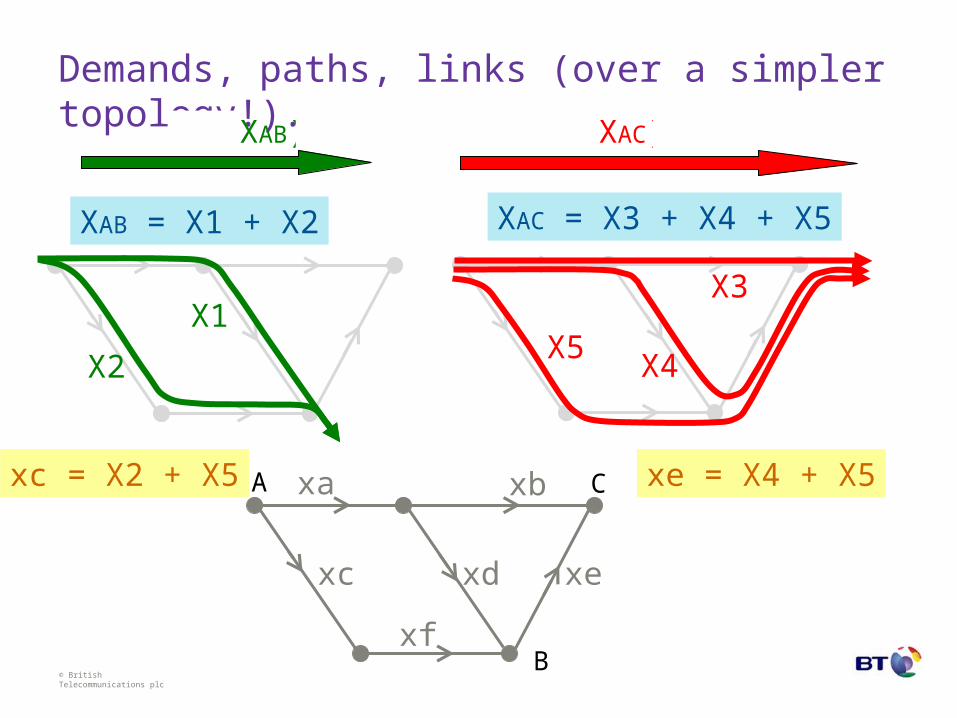
Demands, paths, links (over a simpler topology!).
XAC = X3 + X4 + X5XAB = X1 + X2
xc = X2 + X5 xe = X4 + X5
UAB(XAB) UAC(XAC)
X1
X2
X3
X4X5
xa
xc xd xe
xf
A C
B
xb

© British Telecommunications plc
xa
xc xd xe
xf
Optimisation formulation.
A C
B
UAB(XAB) UAC(XAC)
XAC = X3 + X4 + X5XAB = X1 + X2
max +
xc = X2 + X5 xe = X4 + X5
X1
X2
X3
X4X5
xb

© British Telecommunications plc
xa
xc xd xe
xf
Optimisation formulation.
A C
B
X1
X2
X3
X4X5
X = H X
max
such that
xc = X2 + X5 xe = X4 + X5xb
U(X)

© British Telecommunications plc
xa
xc xd xe
xf
Optimisation formulation.
A C
B
X = H X
max
such that
xc = X2 + X5 xe = X4 + X5xb
X ≥ 0
U(X)

© British Telecommunications plc
Optimisation formulation.
x = A X
max
X = H Xsuch that
xa
xc xd xe
xf
A C
B
xb
X ≥ 0
U(X)

© British Telecommunications plc
Optimisation formulation.
x = A X
max
X = H Xsuch that
X ≥ 0
k ≥ x
U(X)

© British Telecommunications plc
Optimisation formulation.
x = A X
max
X = H Xsuch that
X ≥ 0
k ≥ x
U(X) The (global) objective or utility function
The (shared) constraints
© British Telecommunications plc
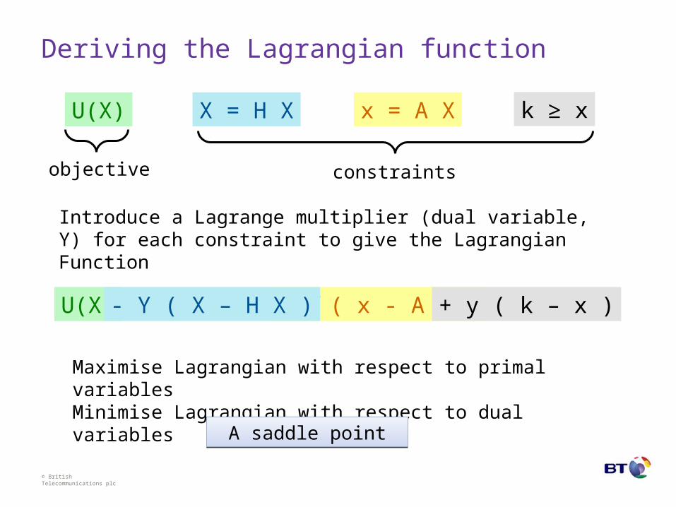
Deriving the Lagrangian function
U(X) + y ( x - A X )- Y ( X – H X ) + y ( k – x )
x = A XX = H X k ≥ xU(X)
objective constraints
Introduce a Lagrange multiplier (dual variable, Y) for each constraint to give the Lagrangian Function
Maximise Lagrangian with respect to primal variablesMinimise Lagrangian with respect to dual variables
A saddle pointA saddle point

© British Telecommunications plc
Component Graph construction.
UAB(XAB) + …
- YAB ( XAB – X1 – X2 ) + … X ≥ 0XAB
YAB
X1 X2
UAB(XAB)
-YAB XAB
+YAB X1 +YAB X2Primal variables
Dual variables
Terms from Lagrangian

© British Telecommunications plc
Component Graph for Multipath Routing.
Path selection
Network interface
Flow aggregation
Capacity constraint
Utility functionX
Y
X
Y
X
y
x
y
AB AC
12 5 4 3
c f d a e b
+U(X)
-YX
+YHX
-YX
+YX
-yAX
+yx
-yx
+yk

© British Telecommunications plc
Decomposition, message passing, feedback loop.Set admitted flow X, given least path price Y,X=argmax[ U(X) – YX ]
Select least cost path
Aggregate flow from allpaths using each link
Set congestion price y of each link
Distributed congestion priceamongst paths using each link
Congestion price accumulated alongeach path.
Determine least cost over available paths
Flow launched into networkpropagates tolinks on selected path

© British Telecommunications plc
Stability and convergence:standard recipe
• Variables adjusted slowly – while propagating their values over the graph.
• Modelled as differential equations.– several different versions (primal, dual, ...)
• Concave-convex assumption leads to convergence proof– via Lyapunov function
• Assumes negligible propagation delay
These are rather limiting assumptions.Would like to investigate discrete changes to flow levels. i.e. transitions.
What about model checking?
These are rather limiting assumptions.Would like to investigate discrete changes to flow levels. i.e. transitions.
What about model checking?

© British Telecommunications plc
Hopes for model checking
• Move away from differential equation dynamics to discrete transitions and state space– Sources move traffic between paths in discrete chunks– Links are either congested or not. Sudden link failures
• Tool to answer more detailed questions about dynamics– Does it stabilise? How long does it take to reconfigure?– What is the maximum amount of traffic that we might loose
following a failure– How does link delay affect reconfiguration time or stability?– Expose unanticipated behaviour
• Design framework– complementing optimisation

© British Telecommunications plc
Fears for model checking
• State explosion• State explosion• State explosion
– But can any tricks within the repertoire of model checking or, possibly, tricks inspired by optimisation mitigate against this?
• Becoming familiar with the logical formalism (CTL etc.)– But that’s not really a fundamental problem! It was actually an
attraction.

© British Telecommunications plc
Our experiments and experiences summarised
• Built several different models– variations on agent behaviour and connectivity
• Tried several different environments: – NuSMV, SPIN, UPPAAL and Verics
• Discrete versions of the source flow and link price variables, and of the dynamics. – with an attempt, not wholly convincing, to maintain some
formal similarity between the transition rules and well-known differential equations for this problem
• State explosion was indeed a problem right from the start.• This restricted us to a very simple network topology.• Struggled over interpretation of interleaving semantics.

© British Telecommunications plc
Simple topology
A
FE
DC
B
Three flows, each has choice of two paths.Three link, each used by two paths.Each path uses on one link.Links have capacity constraints.
© British Telecommunications plc
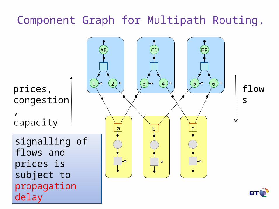
Component Graph for Multipath Routing.
AB
21
a b c
CD
43
EF
65flowsprices,
congestion,capacity
signalling of flows and prices is subject to propagation delay
signalling of flows and prices is subject to propagation delay

© British Telecommunications plc
Component Graph for Multipath Routing.
a
c
2 1
Those pesky dining philosophers again???Those pesky dining philosophers again???

© British Telecommunications plc
Interpretation of non-determinismTwo aspects:-
• Degeneracy in the solution for each agents individual actions (easy) – e.g. choice between two paths if both have equal cost
• Interleaving semantics (harder)– we could understand different choice in the abstract model
• sources synchronous, sources asynchronous, etc...
– but struggled to relate these to temporal behaviour of the underlying ‘real’ system.
– the dynamics of the model are very weakly specified.• this should be useful for modelling uncertainty or
obliviousness to propagation delay (all possibilities are represented)

© British Telecommunications plc
What is the model actually modelling?Example interleaving assumption.
• Each source agent acts asynchronously. – Changes are propagated through resources (links) before any
other source agent acts.
• How is this ‘faithful’ to the underlying ‘real’ system? – if sources act infrequently compared to the propagation delay
across the networks– no hidden ‘on the fly’ state. The state space is well captured as
the product space of all the agents.
• But this limitation is not so completely different from the limitation of modelling the dynamics using differential equations!– infrequent updates c.f. slow updates.

© British Telecommunications plc
How to get a better grip on time evolutionModelling on-the-fly state?
• As a ‘shift register’ between agents– rather like modelling explicit buffers
• Or by timing the arrival of a signal– UPPAAL and timed model checking.
• This explodes the state space– but can the explosion be offset by greater determinism?– probably depends partly on how the model checkers work.
• We were not greatly successful in this direction.
Unfinished business here!Unfinished business here!

© British Telecommunications plc
Stepping back
• The types of systems we are investigating are feedback systems (with complex topology).
• In such systems we are typically interested in asking questions about stability, convergence time, robustness, etc.
• Doing any of the following might destabilise the system– increase step size– increase action frequency– increase propagation delay (round trip time)
• So these quantities are linked– and this should be reflected somehow in the model building.

© British Telecommunications plc
Stepping even further back
• Optimisation v.s. logic– can specify a global objective as a Lagrangian function
depending on lots of system variables.– could also specify a global objective as a logical formula
depending on lots of system variables.
• But optimisation has a notion of convexity– property that is independent of system size– guarantees convergence, independent of topology– forms the boundary of complexity. Non-convex problems are
combinatorially difficult. e.g constraint satisfaction problems.
• What equivalent to convexity is there in logic?– currently exploring A/G framework, linking in with component
graphs

© British Telecommunications plc
Conclusions
• Don’t forget optimisation (+ game theory + control ...) as formal framework.
• Component graph representation opens up window onto many other interesting subjects
• Still believe model checking should be able to illuminate issues not visible through optimisation, but– formalism has some issues
• state space explosion, temporal details.
– practitioner has some issues• interpretation in this setting

Questions

© British Telecommunications plc
Optimisation decomposition
• Optimisation has a long pedigree of applications to networking (planning, routing, traffic engineering, flow control).
• Global view of network objective. (c.f. game theory)• A global problem can be solved by breaking it down into
interacting sub-problems. • Many algorithms (and protocols in a distributed setting)
can be derived this way – e.g. Shortest path formulated as minimum cost flow gives
Bellman Ford algorithm.
• This provides an elegant framework for reasoning about (some simple types) of distributed processes.

© British Telecommunications plc
Logical + discrete models
• But optimisation methods seem quite different in style to models of interacting systems frequently favoured by computer science (process calculus, model checking, petri-nets) where logic plays a more prominent role in specification.
• Our investigation sought to place model checking alongside optimisation in analysing a multipath routing problem of interest to BT (and others).

© British Telecommunications plc
Component Graph
• Graphical syntax for Lagrangian function• Formally similar to
– Factor Graphs– Constraint graphs
• but we have primal and dual variables
• Tool for visualisation of– structure of Lagrangian– sparseness of components– decomposition
• Algorithm (distributed) is modelled as message passing over this graph. Strongly related to– message passing algorithms in coding – marginalisation and belief propagation– constraint propagation in constraint satisfaction algorithms
© British Telecommunications plc
Stepping back – 2tentative position statement
• The standard model checking recipe is quite precise about agent steps, but utterly vague (deliberately so) about their corresponding time steps.
• All possible time evolutions are projected onto one transition system.
• This projection is forgetful of the important structural properties underlying the behaviour or constraints we are interested in
• How to identify interesting traces and recover interesting stability constraints etc.
• I seem to be arguing for timed model checking, but is this enough?