Embed Size (px)
Citation preview

To be published in Photomask Technology 2011 Proc. of SPIE Vol. 8166, 2011
Optimization of mask shot count using MB-MDP and lithography simulation
Gek Soon Chua*a, Wei Long Wanga, Byoung IL Choi a, Yi Zoub, Cyrus Taberyb,
Ingo Borkc, Tam Nguyenc, Aki Fujimurac
a GLOBALFOUNDRIES Singapore, 60 Woodlands Industrial Park D St 2, S 738406, Singapore b GLOBALFOUNDRIES USA, 840 N. McCarthy Blvd. Milpitas, CA 95035, USA
c D2S Inc. 4040 Moorpark Ave, Suite 250, San Jose, CA 95117, USA
ABSTRACT
In order to maintain manageable process windows, mask shapes at the 20nm technology node and below become so complex that mask write times reach 40 hours or might not be writeable at all since the extrapolated write time reaches 80 hours. The recently introduced Model Based Mask Data Preparation (MB-MDP) technique is able to reduce shot count and therefore mask write time by using overlapping shots. Depending on the amount of shot count reduction the contour of the mask shapes is changed leading to the question how the mask contour influences wafer performance.
This paper investigates the tradeoff between mask shot count reduction using MB-MDP and wafer performance using lithography simulation. A typical Source-Mask-Optimization (SMO) result for a 20nm technology will be used as an example.
Keywords: Photo mask, shot count, model based, lithography simulation, process window, SMO, ILT, MDP
1. INTRODUCTION
The ability to use curvilinear features for mask lithography becomes critical, especially for SMO & advanced mask optimization (such as Inverse Lithography Techniques (ILT)) for 20nm technology. However, ideal mask shapes are virtually not writeable because of the unmanageable mask writing times. The conventional approach is to "Manhattanize" the shapes used to create the mask patterns so that the masks can be written using only rectangular variable shaped-beam (VSB) shots. However there is a trade-off between complexity of optimized mask, mask write time & lithographic performance[1]. Several shot count reduction techniques for SMO & ILT Manhattanized masks have been introduced, such as Mask Grid Approximation, Jog smoothing[2], L-shaped-beam shot[3] and overlapping shot from Model Based Mask Data Preparation (MB-MDP)[4] to address the appropriate amount of trade-off.
Besides, the integration of mask process correction (MPC) into OPC modeling and inclusion into a post tapeout flow is likely to be required in the future technology nodes. Several reports for mask process correction application in both tapeout[5-7] and mask manufacturing[8-9] are discussed vigorously. The integrated optics and mask modeling scheme can be applied on various lithography systems, such as EUV lithography, multiple patterning and inverse lithography & source-mask optimization and will compel stringent requirements for runtime and data integrity.
In this paper, we will discuss the lithographic quality trade-off attained from shot count reduction using overlapping shots in Model Based Mask Data Preparation (MB-MDP) technique. MB-MDP technique is very effective for writing complex curvilinear or Manhattanized shapes on masks without exploding shot count by using overlapping shots[10-11]. This paper extends that work applying MB-MDP to Ideal ILT shapes to harness the process window of an “ideal” mask shape while reducing shot count even compared to a conventionally fractured Manhattan-type mask shape. By mimicking the post-OPC ideal mask shape, approximately 30% shot count reduction compared to the Manhattanized mask can be achieved, without compromising litho performance and mask data size.

To be published in Photomask Technology 2011 Proc. of SPIE Vol. 8166, 2011
2. MODEL-BASED MASK DATA PREPARATION FOR THE 20NM NODE
Current OPC modeling assumes that the mask pattern equals the pattern data without considering the mask process beyond a mask-wafer bundled model and a corner rounding model for mask shapes. However taking into consideration the e-beam forward & back scattering as well as mask process effects such as develop, bake and etch, the resist edge on the mask will not be the same as the drawn edge, particularly for sub-80nm features with many sub-50-nm Manhattan jogs. MB-MDP, on the other side, simulates e-beam blur and mask processing effects generating VSB shots which print the desired mask shapes. It is aware of Backscattering (PEC), Fogging (FEC), and Loading (LEC) on the e-beam writer. Because of the simulation effort longer runtime of MB-MDP is expected. Nevertheless, as shown in Figure 1, performing MB-MDP based on Ideal OPC shapes (using overlapping shots) more than makes up for the longer MDP runtime since first, it eliminates the time needed for ILT Manhattanization; second, it already includes MPC so there is no need for a dedicated MPC step, and third, it reduces mask write time by facilitating the overlapping shot technique.
Flow with MB-MDP
Current flow with ILT-OPCPattern Correction for Wafer
(OPC)Fracturing
(MDP)Pattern Correction
for mask (MPC) Mask Writing
OPC withoutManhattanization
Model Based-MDP(incl. MPC) Mask Writing
Figure 1 Illustration of cycle time benefits with MB-MDP flow for 20nm ILT
3. TERMINOLOGY & METHODOLOGY
A. DESCRIPTION OF TEST CASE PREPARATION
In this simulation study the lithographic performance of four different masks is compared. The first mask is based on the rule-based SRAF OPC approach and is fractured conventionally. This mask is labeled “Conventional OPC mask shape” in Figure 2 and is used to compare the results to an established OPC technology.
MB-MDP based on Ideal OPC shape (using overlapping shots)
Conventional RET/OPCRule-based SRAF
Conventional OPC mask shape
MB-MDP mask shape
Ideal OPC data(used as simulationreference)
ILT Manhattanizedmask shape
Manhattanized with specified resolution and according to MRC rules
Freeform RET OPCIdeal OPC shape
Conventional fracturing of Manhattanized OPC shape
Conventional fracturing of conventional OPC shape
Freeform RET OPCIdeal OPC shape
ConventionalOPC output ILT OPC output
Figure 2 Illustration of the four different mask shapes used for verification: Besides the conventional OPC with rule-based SRAFs three different versions of an ILT output are used: a) the ideal curvilinear mask shape, b) a Manhattanized and conventionally fractured mask shape, and c) a MB-MDP generated mask shape.

To be published in Photomask Technology 2011 Proc. of SPIE Vol. 8166, 2011
The second mask is based on an ILT engine without applying any Manhattanization so the OPC data is curvilinear in shape. This mask is labeled “Ideal OPC data” and is used as simulation reference assuming the shapes can be generated on a mask without any limitations in shot count, MRC limits or Manhattanizing resolution. The third mask is also based on the ILT engine, however, instead of outputting curvilinear shapes, the ILT engine Manhattanizes the data so that it can be fractured by conventional tools without exploding shot count. This mask is labeled “ILT Manhattanized mask shape” and is used as a reference for the conventional shot count. Finally, the forth mask is based on the “Ideal OPC data” without any Manhattanization and the mask data is prepared using MB-MDP and overlapping shots. This mask is labeled “D2S MB-MDP mask shape” in Figure 2. The different mask shapes described above are used to determine the lithographic tradeoff between mask shot count reduction using conventional fracturing (Manhattanization) and shot count reduction using MB-MDP (overlapping shots).
B. MODEL-BASED MASK DATA PREPARATION (MB-MDP)
MB-MDP as introduced in previous papers[10-14] combines shot count reduction by using overlapping shots and Mask Process Correction (MPC) in one step. Since MB-MDP simulates the resulting mask contour in a similar way that OPC does on the wafer level, MB-MDP enables the use of overlapping shots, dose modulation of individual e-beam shots and character projection. Figure 3 illustrates the effectiveness of using overlapping shots for the self-aligned via example used in this study.
a) 13 shots conventional
b) 7 shots MB-MDP
c) 5 shots MB-MDP
Figure 3 Illustration of shot count reduction with overlapping VSB shots for self-aligned SRAM Via. Image a) shows the Manhattanized and conventionally fractured via using 13 VSB shots. The resulting simulated mask shape is smaller than the ideal mask shape in several areas (green color) while it is larger than the ideal shape in others (red color). Image b) and c) show shot configurations extracted by MB-MDP using 7 VSB shots and 5 VSB shots respectively. A comparison of the resulting mask shape with the ideal shape shows a better match than the Manhattanized version i.e. only very small red or green areas near the edges are visible in b) and c).
Besides the shot count reduction benefit Figure 3 demonstrates the ability to create better mask shapes with a simulation based MDP flow. Since MB-MDP is aware of e-beam and mask effects, it can account for those effects during shot placement and optimize both concurrently.
As indicated earlier in this paper, a simulation-based method requires calibrated models in order to produce the correct results, in our case shots of the correct size and exact placement. For MB-MDP the model has to account for short- and mid-range scattering effects as well as mask processing effects like develop, bake, and etch. When comparing MB-MDP results with mask and wafer measurements prior model calibration is required. In this simulation-based study, however, a rigorous model calibration is not required. Instead a generic e-beam forward scattering range of 30nm was used and it was assumed that the e-beam machine corrects for backscattering (PEC), loading (LEC), and fogging (FEC). The use of such a generic model does not change the validity of the results in principle as the use of a calibrated model would change shot sizes only marginally but result in the same shot configurations and therefore in the same shot count.

To be published in Photomask Technology 2011 Proc. of SPIE Vol. 8166, 2011
C. LITHOGRAPHY SIMULATION CONDITIONS
The lithography simulation focus is to investigate the impact of process window degradation of mask shapes using conventional fracturing and MB-MDP. The mask shapes from conventional fracturing and MB-MDP were simulated under typical optical conditions of a 20nm node as summarized in Table 1. The verification conditions for determining Depth of Focus (DOF), Mask Error Enhancement Factor (MEEF), and Process-Variation Band (PV-Band) are summarized in Table 2. Table 1. Optical simulation conditions
Optical Conditions NA 1.3
Illumination Mask
C-quad COG
Table 2. Verification conditions
Criteria Conditions DOF 10% CD variation at nominal dose
MEEF +/- 0.25nm of mask bias PV Band & Hotspot With the process variation:
1) Defocus = {-58nm, 0, 58nm} 2) EL = {-3.14%, 0, 3.14%} 3) Mask bias = {-0.25nm, 0, 0.25nm)
4. RESULTS AND DISCUSSION
A. LITHOGRAPHY SIMULATION VERIFICATION ON 20NM VIA SRAM
Figure 4 shows the PV band verification for 4 different mask shapes as described in section 3A. The results show that the curvilinear ideal OPC shape will produce the best wafer results. The traditional rule-based SRAF OPC will no longer be satisfactory for sub-80nm features as depicted in Figure 4a) with the worst PV band at 2.18x using the PV band of the ideal mask shape as a reference. It makes sense that the most effective shapes on masks are curvilinear with worst PV band at 1.64x as shown in Figure 4d). Nonetheless, curvilinear mask shapes are so complex and non-manufacturable at this point, the next practical approach is to Manhattanize the ideal OPC shape as shown in Figure 4b). While the PV band for the Manhattanized mask shape is improved over the traditional rule-based SRAF OPC, it still falls short of the ideal OPC performance. This is because the final mask image of the Manhattanized OPC shape deviates from the ideal mask shape . Furthermore, the Manhattanized mask shot count is around five times more than the traditional rule-based SRAF OPC mask. This would result in a longer OPC runtime and longer mask writing time which are costly and may not be justifiable for the relatively small lithographic improvement.
Model-based mask data preparation (MB-MDP) technique as presented in Figure 4c) is able to reduce shot count by more than 30% compared to the Manhattanized mask. The shot count using MB-MDP with overlapping shots is only 3.5 times the traditional rule-based SRAF OPC mask. The normalized worst PV band of the MB-MDP mask is 1.75x which is significantly better than the worst PV band of the Manhattanized mask which shows an increase of 2.15x. Even at 30% shot count reduction, the contour of the MB-MDP mask shape is closer to the ideal OPC mask contour and results in the best manufacturable wafer performance.
Figure 5 shows the MEEF verification for the 4 different mask shapes. Comparing the MEEF histogram in Figure 5b) for the Manhattanized OPC shape with Figure 5c) for the MB-MDP mask shape, there are more counts of lower MEEF for the MB-MDP version compared to the Manhattanized version.

To be published in Photomask Technology 2011 Proc. of SPIE Vol. 8166, 2011
a) a)
b) b)
c) c)
d) d)
Figure 4 PV Band verification for different mask shapes
Figure 5 MEEF verification for different mask shapes
A reason for the degraded lithography performance of the Manhattanized mask can be seen in Figure 6. Shown on the right side of Figure 6 is the location with the largest error between the MB-MDP mask and the ideal mask shape while the left side of Figure 6 shows the same location for the Manhattanized mask. The comparison shows that the MB-MDP mask follows the ideal mask shape more closely than the Manhattanized mask since the use of overlapping shots allows following the ideal shape closely without exploding the shot count.
Figure 6 Location of maximum error between the ideal mask shape and the simulated mask shape after Manhattanization (left image) and MB-MDP (right image). The MB-MDP mask contour follows the ideal contour much closer than the Manhattanized mask.
Worst PV band is 2.18x
Worst PV band is 2.15x
Worst PV band is 1.75x
Worst PV band is 1.64x
Worst MEEF is 1.36x
Worst MEEF is 1.53x
Worst MEEF is 1.48x
Worst MEEF is 1.31x
18nm max error42nm max error

To be published in Photomask Technology 2011 Proc. of SPIE Vol. 8166, 2011
Figure 7 shows the DOF verification for the 4 different mask shapes. The traditional rule-based SRAF OPC cannot provide adequate DOF for 20nm Via SRAM as highlighted in Figure 7a). There are 830 worst DOF (unusable) counts, twice as much than worst DOF counts for Manhattanized mask shape as shown in Figure 7a) and Figure 7b). The worst DOF counts are significantly reduced for the ideal ILT mask due to better seeding and placement of SRAFs around the main patterns as shown in Figure 7d. By controlling the contour of the mask shape through mask simulation and overlapping shots, DOF of the MB-MDP mask in Figure 7c) is closer to what an ideal OPC mask can offer as shown in Figure 7d) and further reduce the worst DOF counts.
Apart from the PV band, MEEF and DOF check, the via size accuracy is also checked for different mask shapes as shown in Figure 8. The results show clearly that the most effective shapes on mask are curvilinear as depicted in Figure 8d). As seen in Figure 8a) for traditional rule-based SRAF OPC, via size is about 10% bigger. Compared with Figure 8c) for MB-MDP, there is an increased number of bigger (closer to target) vias using MB-MDP.
Table 3 gives an overall comparison of the various verification checks for 20nm Via SRAM, comparing all 4 different mask shapes. The comparison chart shows that MB-MDP is able to harness the benefits of larger process window for an ideal OPC mask solution with manageable shot counts and mask writing time. MB-MDP provides the closest match for enabling complex assist features to print the critical 20nm Via SRAM with no show-stopper on unmanageable e-beam write times. MB-MDP enables the reality for curvilinear ideal ILT patterns using production e-beam writers to enlarge the process window for 20nm Via layer.
a) a)
b) b)
c) c)
d) d) Figure 7 DOF verification for different mask
shapes Figure 8 Via area verification for different mask shapes
Worst DOF count is 830
Worst DOF count is 440
Worst DOF count is 22
Worst DOF count is 57

To be published in Photomask Technology 2011 Proc. of SPIE Vol. 8166, 2011
Table 3 Comparison chart summarizing the verification results for the 4 different mask types studied here
Normalised Worst PVBand
Worst MEEF
Worst DOF
counts
Min Via size
Soft Bridge
Soft Pinch
SRAF print
Fail print
Shot count (normalized)
Conventional OPC mask shape
2.18 1.36 830 1.1 0 0 0 0 1
ILT Manhattanizedmask shape
2.15 1.53 440 0.7 0 0 0 0 5
D2S MB-MDP mask shape
1.75 1.48 22 0.9 0 0 0 0 3.5
Ideal OPC data 1.64 1.31 57 0.9 0 0 0 0 Not manufacturable
B. LITHOGRAPHY SIMULATION VERIFICATION ON THROUGH PITCH
In 20nm Via layer design, square (round) shapes, slightly rectangular, and rectangular bar-like shapes have to print simultaneously. The self-aligned via schemes can result in some fairly long bars. These varied shapes make SRAF placement more complicated.
In this study, the PV band through pitch for rectangular bar-like self-aligned via (SAV) are investigated. Figure 9 compares the PV band through pitch for Self-aligned Vias for ILT Manhattanized OPC and Ideal OPC data. In contrast to the other lithography simulations, in this particular case the rectangular mask shape is used as input for the lithography simulation. Using this rectangular OPC data, the PV bands do not show significant differences between ILT Manhattanized and Ideal data. This illustrates the convergence of the OPC tool to perform Manhattanization. Based on a 45% shot count reduction, the PV band through pitch for the MB-MDP mask shape also does not show major differences (less than 1nm across pitch) to the Ideal OPC data as shown in Figure 10.
Figure 9 Self-aligned Vias through pitch for ILT Manhattanized OPC and Ideal OPC data
Figure 10 Self-aligned Vias through pitch for MB-MDP mask shape and Ideal OPC data
However as shown in Figure 11 using the simulated mask shape as input instead of the rectangular shape, the PV band for the conventionally fractured Manhattanized mask is worse across pitches because the Manhattanization does not consider e-beam and mask processing effects. These depict some performance degradation and portrays as higher PV band through pitch for ILT Manhattanized mask shape. This result shows there is a prevailing relationship between the Manhattanizing step, shot count and lithographic performance.
Figure 12 shows the ideal SAV shape (red contour) resembling an hour glass. Based on varying Manhattanizing jogs, the final OPC data can deviate from the ideal SAV shape. SAV at pitch 180 is selected for a quality vs. mask shot count reduction trade-off study as the PV band at pitch 180 is the largest across all pitches.
To be published in Photomask Technology 2011 Proc. of SPIE Vol. 8166, 2011
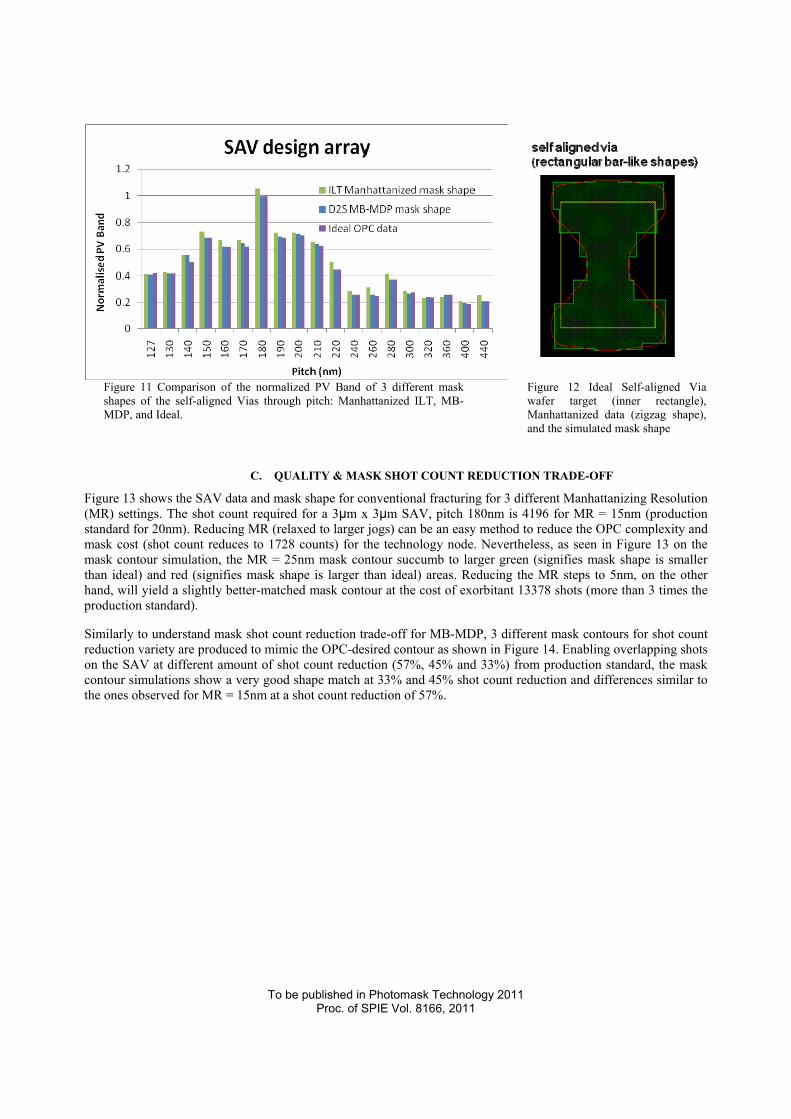
Figure 11 Comparison of the normalized PV Band of 3 different mask shapes of the self-aligned Vias through pitch: Manhattanized ILT, MB-MDP, and Ideal.
Figure 12 Ideal Self-aligned Via wafer target (inner rectangle), Manhattanized data (zigzag shape), and the simulated mask shape
C. QUALITY & MASK SHOT COUNT REDUCTION TRADE-OFF
Figure 13 shows the SAV data and mask shape for conventional fracturing for 3 different Manhattanizing Resolution (MR) settings. The shot count required for a 3µm x 3µm SAV, pitch 180nm is 4196 for MR = 15nm (production standard for 20nm). Reducing MR (relaxed to larger jogs) can be an easy method to reduce the OPC complexity and mask cost (shot count reduces to 1728 counts) for the technology node. Nevertheless, as seen in Figure 13 on the mask contour simulation, the MR = 25nm mask contour succumb to larger green (signifies mask shape is smaller than ideal) and red (signifies mask shape is larger than ideal) areas. Reducing the MR steps to 5nm, on the other hand, will yield a slightly better-matched mask contour at the cost of exorbitant 13378 shots (more than 3 times the production standard).
Similarly to understand mask shot count reduction trade-off for MB-MDP, 3 different mask contours for shot count reduction variety are produced to mimic the OPC-desired contour as shown in Figure 14. Enabling overlapping shots on the SAV at different amount of shot count reduction (57%, 45% and 33%) from production standard, the mask contour simulations show a very good shape match at 33% and 45% shot count reduction and differences similar to the ones observed for MR = 15nm at a shot count reduction of 57%.

To be published in Photomask Technology 2011 Proc. of SPIE Vol. 8166, 2011
= 5nm= 15nm= 25nmC
onve
ntio
nal f
ract
urin
gManhattanizing resolution
Shot count reduction
MB
-MD
P
45% 33%57%
Figure 13 Self-aligned Via Manhattanized input data (top), fractured data (center), and simulated mask shapes (bottom) for conventional fracturing at 3 different resolutions for Manhattanization
Figure 14 Self-aligned Via Ideal input data (top), MB-MDP generated shots (center), and simulated mask shapes for 3 different shot count reduction values
Figure 15 Mask shape comparison at 33% shot count reduction
Figure 16 Mask shape comparison at 45% shot count reduction
Figure 15 and Figure 16 show the mask shape comparison at 33% shot count reduction and 45% shot count reduction, respectively. The two figures show clearly that the assist features (adopting overlapping shots) for MB-MDP are closer to the ideal assist bar shape for best performance. The assist features from conventional fracturing are too small to help transmit enough light energy or contrast to help the main features.
Finally Figure 17 summarizes the mask shot count trade-off between cost and wafer quality (worst PV band) graphically. The worst PV band verification demonstrates the worst EPE distribution of all edges for SAV across dose, mask bias and focus variation. The conventional fracturing for ILT Manhattanized mask shape shows that relaxing MR to 25nm to achieve a 58% shot count reduction obviously worsens the OPC result further. On the other

To be published in Photomask Technology 2011 Proc. of SPIE Vol. 8166, 2011
side, tightening MRC down to 5nm does not bring the worst PV band down to ideal level. This shows that there is a gap to bring Manhattanized mask shape to achieve the best wafer results with economically acceptable write times. Shot count for conventional fracturing will explode for lower MR settings (MR = 5nm) and is still unable to capture the ideal OPC lithography performance.
From the mask shot count reduction ratio for all test cases, MB-MDP is shown to benefit the most from overlapping shots algorithm, comparing to conventional fracturing. MB-MDP uses overlapping shots to mimic the ideal OPC data/mask shape to realize lithography performance and at the same time achieve significant shot count reduction. With shot count reduction at 33% - 45%, the quality metric “worst PV band” is brought closer to the worst PV band achievable with ideal shapes. This shows that MB-MDP shot count reduction at production worthy quality level is feasible without compromising lithography performance.
PORManhattanizing resolution = 15nm
MR = 5nm
MR = 25nm
Ideal worst PV Band33% shot count reduction
45%
57%
Figure 17 Dependency of the normalized worst PV band on shot count for Manhattanized masks and MB-MDP masks using the Ideal ILT shapes as target. While the mask quality degradation is small for MB-MDP masks at shot count reductions up to 45% compared to the Manhattanized mask with 15nm resolution, all Manhattanized masks show a quality degradation compared to the ideal mask.
5. CONCLUSION Overlapping shots created by MB-MDP enable lowered shot count (and therefore faster write-times) while simultaneously maintaining or improving lithography process window on the wafer. In addition, MB-MDP can simulate the effects of shots to produce the OPC-desired contour on the mask plane. This is effective to reduce shot count for complex masks generated by technologies like Source-Mask Optimization (SMO)/ Full Chip Mask Optimization (FCMO), or Inverse Lithography Technology (ILT).
The effectiveness of MB-MDP is verified on 20nm Via SRAM. It shows that MB-MDP is able to harness the benefits of larger process window for an ideal OPC mask solution with manageable shot counts and mask writing time. Moreover, optimizing mask manufacturability (Manhattanizing resolution & shot count) can be achieved without compromising litho performance & mask data size.

To be published in Photomask Technology 2011 Proc. of SPIE Vol. 8166, 2011
6. FUTURE WORK Evaluation mask is considered to validate the benefits for MB-MDP. For future work, collaboration with a mask shop is planned to compare the fracturing data-size and time between the conventional fracturing method for conventional shapes and MB-MDP’s technique for complex (SMO or ILT) shapes will be carried out. Full chip evaluation of the results in mask-wafer double simulation and with mask and wafer test printing will follow. Final validation can be done on wafer or AIMS.
ACKNOWLEDGEMENTS The authors would like to thank and acknowledge Takamizawa-san, Tsujimoto-san, Hayano-san, Migita-san, Motonaga-san and Takayanagi-san (Dai Nippon Printing, Co. Ltd) for their support & discussion for mask-making in future work.
REFERENCES
[1] Kim, B., Suh, S., Jung, S., Woo, S., Cho, H., Tolani, V., Irby, D., Chen, D., Kim, D., Baik, K., Gleason, B., “Tradeoff between lithographic performance and mask cost of masks made by inverse lithography technology”, Proc. Of SPIE, Vol. 7379, pp. 7379-57, 2009
[2] Ellyn Yang, Cheng He Li, Se Jin Park, Yu Zhu, Eric Guo, “An optimized OPC and MDP flow for reducing mask write time and mask cost”, Proc. Of SPIE, Vol. 7823, pp. 78233E-1, 2010
[3] Emile Sahouria, Amanda Bowhill, “Generalization of shot definition for variable shaped e-beam machines for write time reduction”, Proc. Of SPIE, Vol. 7823, pp. 78230T-1, 2010
[4] Christophe Pierrat, Larry Chau, Ingo Bork, “Mask Data Correction Methodology in the Context of Model-Based Fracturing and Advanced Mask Models”, Proc. Of SPIE, Vol. 7973, pp. 79732J-1, 2011
[5] Timothy Lin, Tom Donnelly, Steffen Schulze, “Model based mask process correction and verification for advanced process nodes”, Proc. Of SPIE, Vol. 7274, pp. 72742A-1, 2009
[6] Jing Xue, Zhijie Deng, Kyoil Koo, James Shiely, Sooryong Lee, Yunqiang Zhang, Yongfa Fan, Thomas Schmoeller, “Integrated Mask and Optics Simulations for Mask Corner Rounding Effect in OPC Modeling”, Proc. Of SPIE, Vol. 7823, pp. 782341-1, 2010
[7] Yasuko, S., George, C., Jen-Shiang, W., Shufeng, B., Rafael, H., Jiangwei, L., Jun, T., Doug, V., Jim, W., Tadahiro, T., Takayuki, O., Takashi, K., Shigehiro, H., Hirohito, A., Yoshiaki, H., Shuichi, T., “Performance and stability of mask process correction for EBM-7000”, Proc. Of SPIE, Vol. 7748, pp. 774814-1, 2010
[8] Dai Tsunoda, Masahiro Shoji, Hiroyuki Tsunoe, “Proximity Effect Correction Concerning Forward Scattering”, Proc. Of SPIE, Vol. 7823, pp. 78233D-1, 2010
[9] Christophe Pierrat, Ingo Bork, “Impact of Model-Based Fracturing on E-beam Proximity Effect Correction Methodology”, Proc. Of SPIE, Vol. 7823, pp. 782313-1, 2010
[10] Fujimura, A., Pierrat, C., Kiuchi, T., Komagata, T., Nakagawa, Y., “Efficiently Writing Circular Contacts on Production Reticles,” Proc. Of SPIE, Vol. 7748-49, 2010
[11] Zable, H. R., Fujimura, A., Komagata, T., Nakagawa, Y., Petersen, J. S., “Writing "Wavy" Metal 1 Shapes on 22nm Logic Wafers with Less Shot Count”, Proc. Of SPIE, Vol. 7748-60, 2010
[12] Fujimura, A., Kim, D., Komagata, T, Nakagawa Y, “Best Depth of Focus on 22nm Logic Wafers with Less Shot Count,“ Proc. Of SPIE, Vol. 7748-50, 2010
[13] Fujimura, A., Kim, D., Bork, I., Pierrat, C., “Writing 32nm-hp Contacts with Curvilinear Assist Features,” Proc. Of SPIE, Vol. 7823-6, 2010
[14] Fujimura, A., Kamikubo, T., Bork, I., “Model-based mask data preparation and impact on resist heating,” Proc. Of SPIE, Vol. 7970-37, 2011