Embed Size (px)
Citation preview
Weld World (2017) 61:453–462DOI 10.1007/s40194-017-0437-x
RESEARCH PAPER
Optimization of resistance welding by using electric servoactuator
Zygmunt Mikno1 ·Mariusz Stepien2 ·Boguslaw Grzesik2
Received: 23 September 2016 / Accepted: 4 February 2017 / Published online: 21 February 2017© The Author(s) 2017. This article is published with open access at Springerlink.com
Abstract The paper is focused on the control of resistanceprojection welding process applied in joining of thin-walledmetal elements. The motion of electrode is generated byelectric servo actuator that controls the force exerted onelectrode or alternatively, just travel itself of electrode. Theprojection welding has been discussed for welding of 1.5mm thick DX53 steel sheets where one sheet containsan embossed projection. Apart of electric servo actuator,another source of force has been described, i.e. pneumaticactuator (classical one), for the reason of comparison. Thesolution where the electric servo operates together withappropriate algorithm makes the new solution that is alter-native for classical, pneumatic one. Optimized motion ofelectrode due to new proposed source of electrode forceor/and travel, based on relevant algorithm yields improvedquality of joints.
Keywords (IIW Thesaurus) Resistance welding ·Pneumatic equipment · Optimization · Projectionwelding · Electrode force
Recommended for publication by Commission III - ResistanceWelding, Solid State Welding, and Allied Joining Process
� Zygmunt [email protected]
Mariusz [email protected]
Boguslaw [email protected]
1 Welding Institute, Gliwice, Poland
2 Silesian University of Technology, Gliwice, Poland
1 Introduction
Resistance welding is one of the primary methods usedfor joining thin-walled elements in the automotive, buildingengineering, electrical engineering, household equipmentmanufacturing and aviation industries.
The technology of resistance welding has been knownand developed for almost 140 years (the first resistancewelded joint dates back to 1877) [1]. The popularity ofresistance welding results from its three both practical andeconomical advantages, i.e. (i) no need to use filler met-als, (ii) short processing time (current flow time of approx.200 ms) and (iii) low cost of energy per one joint (approxi-mately 0.1 US cent). The information presented above refersto the overlap welding of 1-mm thick sheets.
As the cost of the energy mentioned above may seemunreliable, the information presented in Table 1 includesfigures related to the cost of electric energy drawn fromthe power grid in order to power a welding machine whenmaking a welded joint of two sheets (1.0 mm thick each).
When calculating the energy-related costs, it wasassumed that the power efficiency of a welding machineamounted to 6% (i.e. relatively low in the example anal-ysed above) and that the average cost of electric energy inthe USA was 0.12 $/1 kWh [2]. The remaining data used inthe calculations were determined experimentally using a DC250 kVA ZPI90 inverter welding machine (1 kHz) manufac-tured by the ASPA Wroclaw and Welding Institute, Poland(throat depth of a welding machine amounted to 800 mmand window height of 450 mm).
The necessity of making a large number of, mostly over-lap, joints when manufacturing a car body (i.e. between3000 and 5000 welds, depending on the type of a body) isresponsible for the popularity of resistance welding in theautomotive industry [1].
454 Weld World (2017) 61:453–462
Table 1 Costs of electricenergy for welding 1.0-mmthick sheets
I U t Energy Cost of 1 kWh Efficiency Total cost
Of welding
kA V ms Ws Wh $ % $ $cent
8 1.5 200 2.4k 0.67 0.12 6.0 0.0013 0.13
Advantages resulting from the use of the electric servosystem are (i) no need for a compressed air system, (ii)the reduction of noise and (iii) significantly faster travel ofelectrodes.
However, the use of the servo operating force systemrequires that the operating personnel perform additionalpreparatory activities before welding, i.e. (i) adjusting thegeometrical zero of electrodes after each exchange andrefurbishment of electrode terminals and (ii) creating thetable of calibration, i.e. correlation between the servo actu-ator input current and the actual force of welding machineelectrodes.
An important aspect, in terms of the quality of weldedjoints, is the control of a force and/or travel by electric servoactuator ensuring the repeatability and changeability (whennecessary) of welding processes. Such control should leadto the optimization of welding power spatial distribution inthe welding area and, consequently, to the improvement ofwelded joint quality.
The force and electrode travel control during the resis-tance welding process described in the paper is totallydifferent than control processes used so far, and it influenceson existing point of view concerning resistance welding.Advantages of novel solution are visible particularly forrelatively large electrode travel distance during the currentflow, such as can be observed during projection welding.Presented in the paper method is still ongoing. It has beenverified experimentally based on examples of projectionwelding of sheets (embossed projection) and cross-wire.
2 Welding machine characteristics
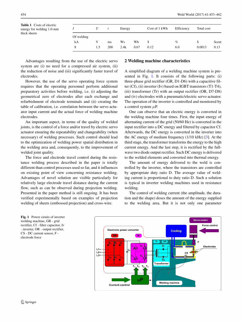
A simplified diagram of a welding machine system is pre-sented in Fig. 1. It consists of the following parts: (i)three-phase grid rectifier (GR, D1-D6) with a capacitive fil-ter (Cf), (ii) inverter (Iv) based on IGBT transistors (T1-T4),(iii) transformer (Tr) with an output rectifier (OR, D7-D8)and (iv) electrodes with a pneumatic/electric servo actuator.The operation of the inverter is controlled and monitored bya control system μP.
One can observe that an electric energy is converted inthe welding machine four times. First, the input energy ofalternating current of the grid (50/60 Hz) is converted in theinput rectifier into a DC energy and filtered by capacitor Cf.Afterwards, the DC energy is converted in the inverter intothe AC energy of medium frequency (1/10 kHz) [3]. At thethird stage, the transformer transforms the energy to the highcurrent energy. And the last step, it is rectified by the full-wave two diode output rectifier. Such DC energy is deliveredto the welded elements and converted into thermal energy.
The amount of energy delivered to the weld is con-trolled by the inverter, where the transistors are controlledby appropriate duty ratio D. The average value of weld-ing current is proportional to duty ratio D. Such a solutionis typical in inverter welding machines used in resistancewelding.
The control of welding current (the amplitude, the dura-tion and the shape) doses the amount of the energy suppliedto the welding area. But it is not only one parameter
Fig. 1 Power ciruits of inverterwelding machine, GR - gridrectifier, Cf - filter capacitor, Iv- inverter, OR - output rectifier,CS - DC current sensor, F -electrode force
Weld World (2017) 61:453–462 455
controlling the energy. The second one, of great impor-tance, is the control of the force that electrodes exert onwelded elements—it is a separate technological problemto be solved. The energy is controlled by the force ofelectrodes because it influences directly on the resistanceof welded elements (the energy is a product of time, squareof current and the resistance). The same can be consideredtaking the power into account.
E = I 2 × R × t (1)
The optimization of a welding process, defined as thecontrol of welding energy and power spatial distribu-tion, is greatly affected by the use of an electric servoforce system and by the application of appropriate con-trol algorithms. Successful optimization process results withimproved repeatability and, consequently, in the better qual-ity of welded joints [3, 4].
3 Areas of application
As was mentioned, the advantages of new solution takeplace, particularly for projection welding, where the techno-logical process is characterized with relative large electrodetravel distance during the current flow (e.g. in comparisonwith resistance overlap spot welding of sheets). The paperis concerned with one variant of resistance welding, i.e.the projection welding of sheets with embossed projections.Basically, the projection welding (including mentionedembossed projection welding) is used when it is necessaryto make several joints at the same time, produce aestheticjoints without indents visible in the material due to forceexerted by electrodes and to obtain the small heat-affectedzone. The quality of welded joints and the repeatability ofprocess are very important in the most of applications. Forexample, modern car bodies contain approximately 300 fas-teners, e.g. bolts, nuts and pins, punched and welded usingthe technology described in this paper. Key elements, suchas the front and rear car axles, are mounted to such fasten-ers; the seat belts and the steering column are anchored tothem and provide grounding for electric wires. The qualitywith which such fasteners are attached to the stamped ele-ments of the car body is of critical importance as regards thesafety and reliability of the finished product [5].
The tests described in [6] and [7] revealed numerousdrawbacks of projection welding related to the applicationof the pneumatic force system. The most important disad-vantages are narrow windows of welding parameters, thelack of process repeatability and, as a result, the deteriora-tion of quality [8]. The change of a projection height playsthe crucial role during the initial heating of the projectionwelding process. The beginning of the welding process isoften accompanied by the formation of a ring weld nugget
and expulsion at the perimeter of the contact area [6, 7, 9]. Indynamic welding processes, e.g. capacitor discharge weld-ing [10] or the welding of aluminum [11], due to a shortcurrent flow time, it is necessary to ensure high dynamicsof force changes. The primary reason for the disadvantagesdescribed is the use of the pneumatic force system character-ized by high mechanical inertia and the lack of force controlpossibility, particularly during the flow of welding current[12].
Alternatively, it is possible to use the electric servo forcesystem whose advantages when carrying out resistancewelding have been discussed in reference publications, e.g.[9]. However, the authors of the aforementioned papers usedonly one of the possible options related to electric servo sys-tem control, i.e. control in relation to force control algorithm[13, 14]. There is another option of the electric servo con-trol system, highly useful during welding, i.e. the control ofelectrode travel, presented and discussed by the authors offollowing publication [4, 9, 15, 16].
4 FEM numerical analysis
4.1 FEM computational model
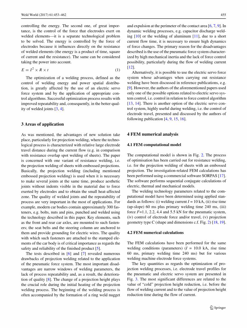
The computational model is shown in Fig. 2. The processof optimisation has been carried out for resistance welding,i.e. for the projection welding of sheets with an embossedprojection. The investigation-related FEM calculations hasbeen performed using a commercial software SORPAS [17].The software performs sequential conjugate calculations ofelectric, thermal and mechanical models.
The welding technology parameters related to the com-putational model have been determined using applied stan-dards as follows: (i) welding current I = 10 kA, (ii) rise time(up-slope) 60 ms plus primary welding time 240 ms, (iii)force F=1.1, 2.2, 4.4 and 5.5 kN for the pneumatic system,(iv) control of electrode force and/or travel, (v) projectiongeometry type C (shape and dimensions c.f. Fig. 2) [18, 19].
4.2 FEM numerical calculations
The FEM calculations have been performed for the samewelding conditions (parameters) (I = 10.0 kA, rise time60 ms, primary welding time 240 ms) but for variouswelding machine electrode force systems.
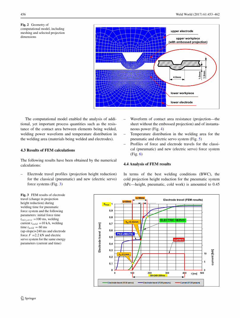
The key quantities as regards the optimization of pro-jection welding processes, i.e. electrode travel profiles forthe pneumatic and electric servo system are presented inFig. 3. The most significant differences are related to thevalue of “cold” projection height reduction, i.e. before theflow of welding current and to the value of projection heightreduction time during the flow of current.
456 Weld World (2017) 61:453–462
Fig. 2 Geometry ofcomputational model, includingmeshing and selected projectiondimensions
The computational model enabled the analysis of addi-tional, yet important process quantities such as the resis-tance of the contact area between elements being welded,welding power waveform and temperature distribution inthe welding area (materials being welded and electrodes).
4.3 Results of FEM calculations
The following results have been obtained by the numericalcalculations:
– Electrode travel profiles (projection height reduction)for the classical (pneumatic) and new (electric servo)force systems (Fig. 3)
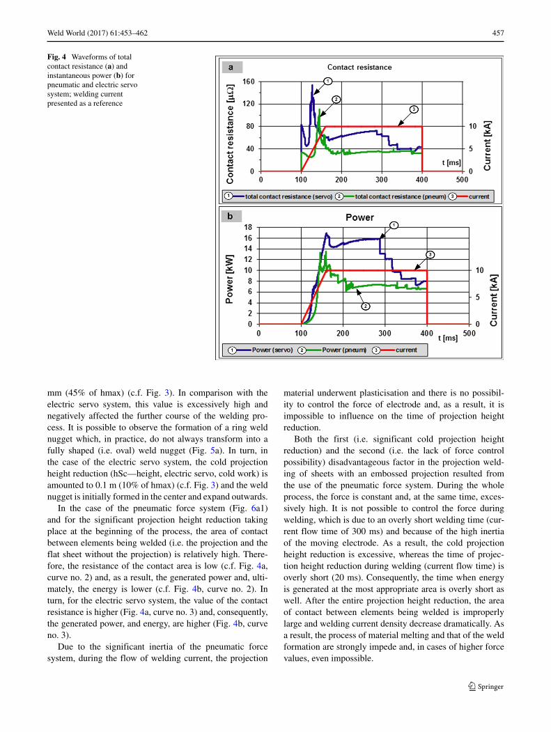
– Waveform of contact area resistance (projection—thesheet without the embossed projection) and of instanta-neous power (Fig. 4)
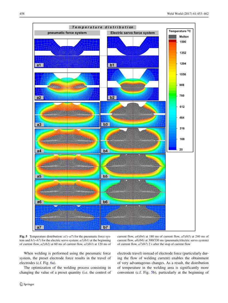
– Temperature distribution in the welding area for thepneumatic and electric servo system (Fig. 5)
– Profiles of force and electrode travels for the classi-cal (pneumatic) and new (electric servo) force system(Fig. 6)
4.4 Analysis of FEM results
In terms of the best welding conditions (BWC), thecold projection height reduction for the pneumatic system(hPc—height, pneumatic, cold work) is amounted to 0.45
Fig. 3 FEM results of electrodetravel (change in projectionheight reduction) duringwelding time for pneumaticforce system and the followingparameters: initial force timetinitf orce =100 ms, weldingcurrent iweld =10 kA, weldingtime tweld = 60 ms(up-slope)+240 ms and electrodeforce F =2.2 kN and electricservo system for the same energyparameters (current and time)
Weld World (2017) 61:453–462 457
Fig. 4 Waveforms of totalcontact resistance (a) andinstantaneous power (b) forpneumatic and electric servosystem; welding currentpresented as a reference
mm (45% of hmax) (c.f. Fig. 3). In comparison with theelectric servo system, this value is excessively high andnegatively affected the further course of the welding pro-cess. It is possible to observe the formation of a ring weldnugget which, in practice, do not always transform into afully shaped (i.e. oval) weld nugget (Fig. 5a). In turn, inthe case of the electric servo system, the cold projectionheight reduction (hSc—height, electric servo, cold work) isamounted to 0.1 m (10% of hmax) (c.f. Fig. 3) and the weldnugget is initially formed in the center and expand outwards.
In the case of the pneumatic force system (Fig. 6a1)and for the significant projection height reduction takingplace at the beginning of the process, the area of contactbetween elements being welded (i.e. the projection and theflat sheet without the projection) is relatively high. There-fore, the resistance of the contact area is low (c.f. Fig. 4a,curve no. 2) and, as a result, the generated power and, ulti-mately, the energy is lower (c.f. Fig. 4b, curve no. 2). Inturn, for the electric servo system, the value of the contactresistance is higher (Fig. 4a, curve no. 3) and, consequently,the generated power, and energy, are higher (Fig. 4b, curveno. 3).
Due to the significant inertia of the pneumatic forcesystem, during the flow of welding current, the projection
material underwent plasticisation and there is no possibil-ity to control the force of electrode and, as a result, it isimpossible to influence on the time of projection heightreduction.
Both the first (i.e. significant cold projection heightreduction) and the second (i.e. the lack of force controlpossibility) disadvantageous factor in the projection weld-ing of sheets with an embossed projection resulted fromthe use of the pneumatic force system. During the wholeprocess, the force is constant and, at the same time, exces-sively high. It is not possible to control the force duringwelding, which is due to an overly short welding time (cur-rent flow time of 300 ms) and because of the high inertiaof the moving electrode. As a result, the cold projectionheight reduction is excessive, whereas the time of projec-tion height reduction during welding (current flow time) isoverly short (20 ms). Consequently, the time when energyis generated at the most appropriate area is overly short aswell. After the entire projection height reduction, the areaof contact between elements being welded is improperlylarge and welding current density decrease dramatically. Asa result, the process of material melting and that of the weldformation are strongly impede and, in cases of higher forcevalues, even impossible.
458 Weld World (2017) 61:453–462
Fig. 5 Temperature distribution: a1)–a7) for the pneumatic force sys-tem and b1)–b7) for the electric servo system: a1)/b1) at the beginningof current flow, a2)/b2) at 60 ms of current flow, a3)/b3) at 120 ms of
current flow, a4)/b4) at 180 ms of current flow, a5)/b5) at 240 ms ofcurrent flow, a6)/b6) at 300/330 ms (pneumatic/electric servo system)of current flow, a7)/b7) 2 s after the stop of current flow
When welding is performed using the pneumatic forcesystem, the preset electrode force results in the travel ofelectrodes (c.f. Fig. 6a).
The optimization of the welding process consisting inchanging the value of a preset quantity (i.e. the control of
electrode travel) instead of electrode force (particularly dur-ing the flow of welding current) enables the obtainmentof very advantageous changes. As a result, the distributionof temperature in the welding area is significantly moreconvenient (c.f. Fig. 5b), particularly at the beginning of
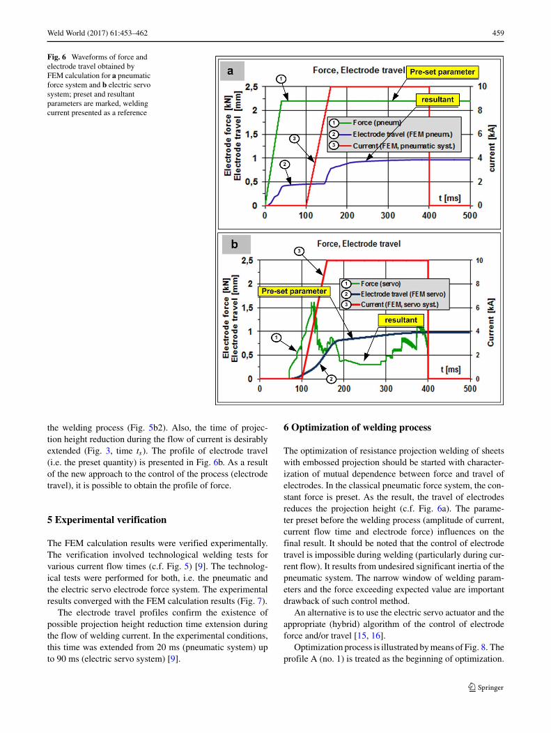
Weld World (2017) 61:453–462 459
Fig. 6 Waveforms of force andelectrode travel obtained byFEM calculation for a pneumaticforce system and b electric servosystem; preset and resultantparameters are marked, weldingcurrent presented as a reference
the welding process (Fig. 5b2). Also, the time of projec-tion height reduction during the flow of current is desirablyextended (Fig. 3, time ts). The profile of electrode travel(i.e. the preset quantity) is presented in Fig. 6b. As a resultof the new approach to the control of the process (electrodetravel), it is possible to obtain the profile of force.
5 Experimental verification
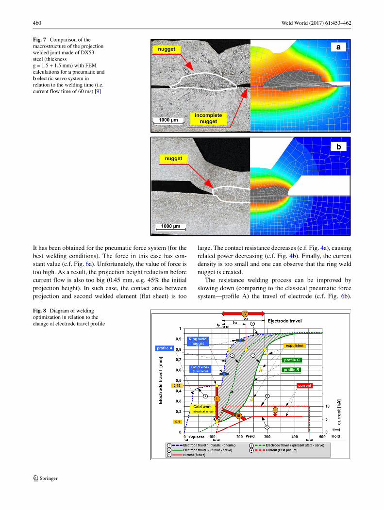
The FEM calculation results were verified experimentally.The verification involved technological welding tests forvarious current flow times (c.f. Fig. 5) [9]. The technolog-ical tests were performed for both, i.e. the pneumatic andthe electric servo electrode force system. The experimentalresults converged with the FEM calculation results (Fig. 7).
The electrode travel profiles confirm the existence ofpossible projection height reduction time extension duringthe flow of welding current. In the experimental conditions,this time was extended from 20 ms (pneumatic system) upto 90 ms (electric servo system) [9].
6 Optimization of welding process
The optimization of resistance projection welding of sheetswith embossed projection should be started with character-ization of mutual dependence between force and travel ofelectrodes. In the classical pneumatic force system, the con-stant force is preset. As the result, the travel of electrodesreduces the projection height (c.f. Fig. 6a). The parame-ter preset before the welding process (amplitude of current,current flow time and electrode force) influences on thefinal result. It should be noted that the control of electrodetravel is impossible during welding (particularly during cur-rent flow). It results from undesired significant inertia of thepneumatic system. The narrow window of welding param-eters and the force exceeding expected value are importantdrawback of such control method.
An alternative is to use the electric servo actuator and theappropriate (hybrid) algorithm of the control of electrodeforce and/or travel [15, 16].
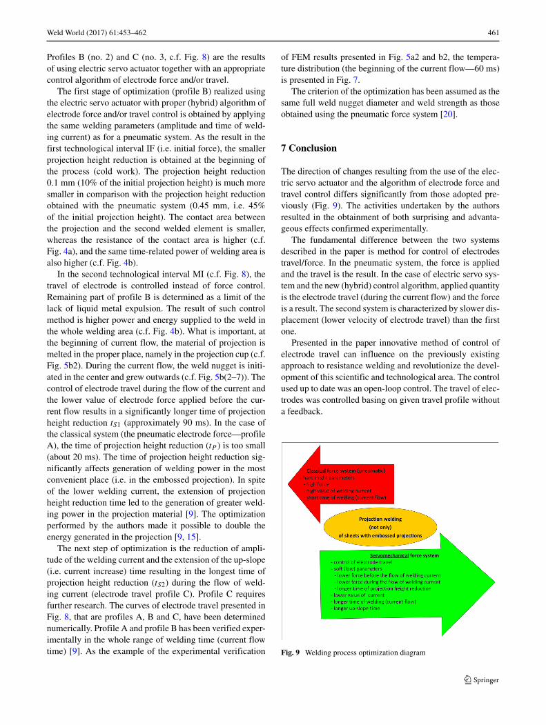
Optimization process is illustrated bymeans of Fig. 8. Theprofile A (no. 1) is treated as the beginning of optimization.
460 Weld World (2017) 61:453–462
Fig. 7 Comparison of themacrostructure of the projectionwelded joint made of DX53steel (thicknessg = 1.5 + 1.5 mm) with FEMcalculations for a pneumatic andb electric servo system inrelation to the welding time (i.e.current flow time of 60 ms) [9]
It has been obtained for the pneumatic force system (for thebest welding conditions). The force in this case has con-stant value (c.f. Fig. 6a). Unfortunately, the value of force istoo high. As a result, the projection height reduction beforecurrent flow is also too big (0.45 mm, e.g. 45% the initialprojection height). In such case, the contact area betweenprojection and second welded element (flat sheet) is too
large. The contact resistance decreases (c.f. Fig. 4a), causingrelated power decreasing (c.f. Fig. 4b). Finally, the currentdensity is too small and one can observe that the ring weldnugget is created.
The resistance welding process can be improved byslowing down (comparing to the classical pneumatic forcesystem—profile A) the travel of electrode (c.f. Fig. 6b).
Fig. 8 Diagram of weldingoptimization in relation to thechange of electrode travel profile
Weld World (2017) 61:453–462 461
Profiles B (no. 2) and C (no. 3, c.f. Fig. 8) are the resultsof using electric servo actuator together with an appropriatecontrol algorithm of electrode force and/or travel.
The first stage of optimization (profile B) realized usingthe electric servo actuator with proper (hybrid) algorithm ofelectrode force and/or travel control is obtained by applyingthe same welding parameters (amplitude and time of weld-ing current) as for a pneumatic system. As the result in thefirst technological interval IF (i.e. initial force), the smallerprojection height reduction is obtained at the beginning ofthe process (cold work). The projection height reduction0.1 mm (10% of the initial projection height) is much moresmaller in comparison with the projection height reductionobtained with the pneumatic system (0.45 mm, i.e. 45%of the initial projection height). The contact area betweenthe projection and the second welded element is smaller,whereas the resistance of the contact area is higher (c.f.Fig. 4a), and the same time-related power of welding area isalso higher (c.f. Fig. 4b).
In the second technological interval MI (c.f. Fig. 8), thetravel of electrode is controlled instead of force control.Remaining part of profile B is determined as a limit of thelack of liquid metal expulsion. The result of such controlmethod is higher power and energy supplied to the weld inthe whole welding area (c.f. Fig. 4b). What is important, atthe beginning of current flow, the material of projection ismelted in the proper place, namely in the projection cup (c.f.Fig. 5b2). During the current flow, the weld nugget is initi-ated in the center and grew outwards (c.f. Fig. 5b(2–7)). Thecontrol of electrode travel during the flow of the current andthe lower value of electrode force applied before the cur-rent flow results in a significantly longer time of projectionheight reduction tS1 (approximately 90 ms). In the case ofthe classical system (the pneumatic electrode force—profileA), the time of projection height reduction (tP ) is too small(about 20 ms). The time of projection height reduction sig-nificantly affects generation of welding power in the mostconvenient place (i.e. in the embossed projection). In spiteof the lower welding current, the extension of projectionheight reduction time led to the generation of greater weld-ing power in the projection material [9]. The optimizationperformed by the authors made it possible to double theenergy generated in the projection [9, 15].
The next step of optimization is the reduction of ampli-tude of the welding current and the extension of the up-slope(i.e. current increase) time resulting in the longest time ofprojection height reduction (tS2) during the flow of weld-ing current (electrode travel profile C). Profile C requiresfurther research. The curves of electrode travel presented inFig. 8, that are profiles A, B and C, have been determinednumerically. Profile A and profile B has been verified exper-imentally in the whole range of welding time (current flowtime) [9]. As the example of the experimental verification
of FEM results presented in Fig. 5a2 and b2, the tempera-ture distribution (the beginning of the current flow—60 ms)is presented in Fig. 7.
The criterion of the optimization has been assumed as thesame full weld nugget diameter and weld strength as thoseobtained using the pneumatic force system [20].
7 Conclusion
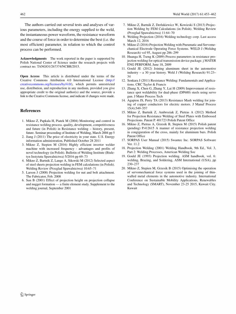
The direction of changes resulting from the use of the elec-tric servo actuator and the algorithm of electrode force andtravel control differs significantly from those adopted pre-viously (Fig. 9). The activities undertaken by the authorsresulted in the obtainment of both surprising and advanta-geous effects confirmed experimentally.
The fundamental difference between the two systemsdescribed in the paper is method for control of electrodestravel/force. In the pneumatic system, the force is appliedand the travel is the result. In the case of electric servo sys-tem and the new (hybrid) control algorithm, applied quantityis the electrode travel (during the current flow) and the forceis a result. The second system is characterized by slower dis-placement (lower velocity of electrode travel) than the firstone.
Presented in the paper innovative method of control ofelectrode travel can influence on the previously existingapproach to resistance welding and revolutionize the devel-opment of this scientific and technological area. The controlused up to date was an open-loop control. The travel of elec-trodes was controlled basing on given travel profile withouta feedback.
Fig. 9 Welding process optimization diagram
462 Weld World (2017) 61:453–462
The authors carried out several tests and analyses of var-ious parameters, including the energy supplied to the weld,the instantaneous power waveform, the resistance waveformand the course of force in order to determine the best (i.e. themost efficient) parameter, in relation to which the controlprocess can be performed.
Acknowledgments The work reported in the paper is supported byPolish National Center of Science under the research projects withcontract no. TANGO1/267374/NCBR/2015.
Open Access This article is distributed under the terms of theCreative Commons Attribution 4.0 International License (http://creativecommons.org/licenses/by/4.0/), which permits unrestricteduse, distribution, and reproduction in any medium, provided you giveappropriate credit to the original author(s) and the source, provide alink to the Creative Commons license, and indicate if changes were made.
References
1. Mikno Z, Papkala H, Piatek M (2004) Monitoring and control inresistance welding process. quality, development, competitivenessand future (in Polish) in Resistance welding – history, present,future. Seminar proceeding of Institute of Welding, March 2004 pp 5
2. Jiang J (2011) The price of electricity in your state. U.S. Energyinformation administration, Published October 28 2011
3. Mikno Z, Stepien M (2016) Highly efficient invertor weldermachine with increased frequency - advantages and profits ofnovel technology (in Polish). Bulletin of Welding Institute (Biule-tyn Instytutu Spawalnictwa) 5/2016 pp 69–73
4. Mikno Z, Bartnik Z, Lange A, Sikorski M (2012) Selected aspectof steel sheets projection welding in FEM calculations (in Polish).Welding Review (Przeglad Spawalnictwa) 10:65–71
5. Larson J (2008) Projection welding for nut and bolt attachment.The Fabricator, Feb. 2008
6. Sun B (2001) Effect of projection height on projection collapseand nugget formation — a finite element study. Supplement to thewelding journal, September 2001
7. Mikno Z, Bartnik Z, Derlukiewicz W, Kowieski S (2013) Projec-tion Welding by FEM Calculations (in Polish). Welding Review(Przeglad Spawalnictwa) 11:64–70
8. Welding Projection (2016) Welding technology corp. Last accessMarch 12, 2016
9. Mikno Z (2016) ProjectionWelding with Pneumatic and Servome-chanical Electrode Operating Force Systems. WELD J (WelidngResearch) vol 95, August pp 286–299
10. Huanga H, Tseng K (2009) Process parameters in resistance pro-jection welding for optical transmission device package. j MATERENG PERFORM, June 18, 2009
11. Gould JE (2012) Joining aluminum sheet in the automotiveindustry – a 30 year history. Weld J (Welidng Research) 91:23–34
12. Senkara J (2011) Resistance Welding: Fundamentals and Applica-tions. CRC Taylor & Francis
13. Zhang X, Chen G, Zhang Y, Lai H (2009) Improvement of resis-tance spot weldability for dual-phase (DP600) steels using servogun. J Mater Process Tech
14. Agapiou JS, Perry TA (2013) Resistance Mash welding for join-ing of copper conductors for electric motors. J Manuf Process15(4):549–557
15. Mikno Z, Bartnik Z, Ambroziak Z, Pietras A (2012) Methodfor Projection Resistance Welding of Steel Plates with EmbossedProjections. Patent P. 401723 Polish Patent Office
16. Mikno Z, Pietras A, Grzesik B, Stepien M (2015) Polish patent(pending) P.412615 A manner of resistance projection weldingin congiguration of the cross, mainly for aluminum bars. PolishPatent Office
17. SORPAS User Manual (2015) Swantec Inc. SORPAS SoftwareVer. 11.2
18. Projection Welding (2001) Welding Handbook, 9th Ed., Vol. 3,Part 2: Welding Processes, American Welding Soc
19. Gould JE (1993) Projection welding. ASM handbook, vol. 6:welding, Brazing, and Soldering, ASM International (USA), pp230–237
20. Mikno Z, Stepien M, Grzesik B (2015) Optimising the operationof servomechanical force systems used in the joining of thin-walled metal elements in the automotive industry. InternationalConference on Sustainable Mobility Applications, Renewablesand Technology (SMART), November 23-25 2015, Kuwait City.Kuwait