Embed Size (px)
Citation preview
OPTIMIZATION OF TOOL LIFE IN MILLING
MOHD EZUWANIZAM BIN MASRAL
Thesis submitted in fulfillment of the requirements
for the award of the degree of
Bachelor of Mechanical Engineering with Manufacturing Engineering
Faculty of Mechanical Engineering
UNIVERSITI MALAYSIA PAHANG
DECEMBER 2010
v
ACKNOWLEDGEMENTS
I would like to express my appreciation and gratitude to my supervisor, Mr.
Kumaran Kadirgama his patience for giving advice and constant support in making this
research possible. I also would like to express very special thanks to lab instructors Mr
Khairul Azha and Mr. Asmizam his suggestions and co-operation throughout the study.
Special thanks are also given to all lecturers for the guidance, experience sharing and
comment on my project thesis.There were not hesitant to answer all my doubts and
spending their time to guide me during my experimental work.
My sincere thanks go to all my labmates and members of the staff of the
Mechanical Engineering Department, UMP, who helped me in many ways and made
my stay at UMP pleasant and unforgettable. My appreciation also goes to my colleagues
and other who provide me with assistance at various occasions.Thier view and tips are
valuable and useful indeed. Not forget to members for their support, advice and
motivation I also wish to express sincere appreciation to all my friends, especially
Faizal and Ahmad Nazmi for their advice and their help to do the study and complete
this project. I benefited greatly from the comments and assistant they give to me.
Most importantly, I would like to thank to my family especially my parents, Mr.
MASRAL BIN BUANG and Mrs. MARIANI BTE OMAR, have guided me throughout
my life. They have always sacrifices their time and continuous support me to achieve
my dreams and goals. I would like to thank them for all support and encouragement
they done for me.
vi
ABSTRACT
This paper discuss of the Optimization of Tool Life in Milling. The objective of the
paper is to obtain an optimal setting of turning process parameters –cutting speed, feed
and depth of cut, which may result in optimizing tool life of TiN coated carbide inserts
while milling aluminium 6061. Data is collected from FANUC Robodrill CNC milling
machines were run by 15 samples of experiments. A dimensional-accuracy model for
the end milling of aluminum alloys under dry conditions is presented. To build the
quadratic model and minimize the number of experiments for the design parameters,
response surface methodology (RSM) with a Box-Behnkin method is used to design the
table in MINITAB packages. The inputs of the model consist of feed, cutting speed and
depth of cut while the output from the model is tool life and tool wear was measured
using Image Analyzer microscope.The model is validated through a comparison of the
experimental values with their predicted counterparts. A good agreement is found where
from the RSM approaches which reliable to be use in tool wear prediction. The direct
and interaction effect of the machining parameter with tool wear were analyzed and
plotted, which helped to select process parameter in order to reduce tool wear which
ensures quality of milling. It is shown that the tool wear in end milling decreases with
the increase in feed, radial depths of cut and cutting. From the experiment it is found
that the effect of axial depth of cut on tool life is not so significant. The speed effect is
dominant followed by the feed and the axial depth of cut. For end-milling of aluminium
alloy 6061, the optimum condition that is required to maximize the coated carbide tool
life are as follow: cutting speed of 180m/min, federate of 0.2 mm/rev, axial depth of 1.5
mm.
vii
ABSTRAK
Kertas kajian ini membincangkan tentang mengoptimum kehidupan mata alat dalam
proses pengilingan. Objektif kertas kerja ini adalah untuk mendapatkan gubahan
parameter yang optimal oleh mesin penggilingan-kelajuan pemotongan,nilai suapan dan
kedalaman pemotongan, yang dimana akan member kesan dalam mengoptimum sisipan
mata alat TiN coated carbide semasa memesin aluminium 6061. Data di kumpul dari
mesin menggiling CNC FANUC Robodrll dimana dijalankan menggunakan 15 sampel
eksperiment. Model dimensi ketepatan untuk proses pengiligan hujung untuk
aluminium aloi dibawah kondisi kering digunakan. Untuk membina model kuadratik
dan mengurangkan jumlah eksperimen untuk rekacipta parameter, response surface
methodology (RSM) dengan cara Box-Behkin digunakan untuk mereka-cipta jadual di
dalam MINITAB. Penghasilan model terdiri daripada nilai suapan, kelajuan
pemotongan dan kedalaman memotong dimana outputnya dari model ini adalah
kehidupan mata alat dan kehausan mata alat di ambil dengan menggunakan Image
Analyzer mikroskop. Kesan laluan dan interaksi parameter pemesinan dan kehausan
mata alat di analisis dan di plot graf dengan, dimana ianya membantu untuk memilih
proses parameter dengan tujuan untuk menurangkan kehausan mata alat dan
memastikan kualiti penggiligan. Itu ditunjukan yang mana kehidupan mata alat dalam
proses menggiling hujung rendah dengan menambahkan nilai pada suapan, jumlah
kedalaman pemotongan dan kelajuan pemotongan. Ini juga didapati bahawa jumlah
kedalaman pemotongan mempunyai signifikan yang paling banyak mempengaruhi
kehausan mata alat didalam proses pemotongan hujung terhadap aluminium aloi.
viii
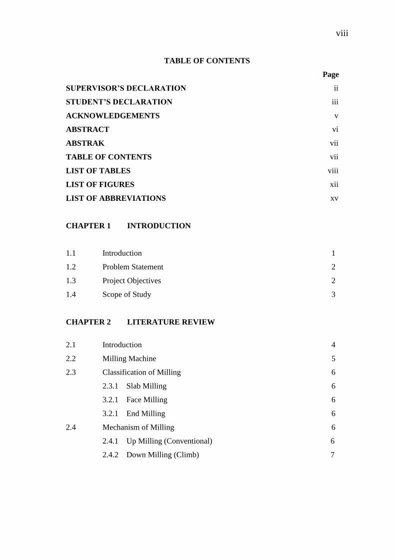
TABLE OF CONTENTS
Page
SUPERVISOR’S DECLARATION ii
STUDENT’S DECLARATION iii
ACKNOWLEDGEMENTS v
ABSTRACT vi
ABSTRAK vii
TABLE OF CONTENTS vii
LIST OF TABLES viii
LIST OF FIGURES xii
LIST OF ABBREVIATIONS xv
CHAPTER 1 INTRODUCTION
1.1 Introduction 1
1.2 Problem Statement 2
1.3 Project Objectives 2
1.4 Scope of Study 3
CHAPTER 2 LITERATURE REVIEW
2.1 Introduction 4
2.2 Milling Machine 5
2.3 Classification of Milling 6
2.3.1 Slab Milling 6
3.2.1 Face Milling 6
3.2.1 End Milling 6
2.4 Mechanism of Milling 6
2.4.1 Up Milling (Conventional) 6
2.4.2 Down Milling (Climb) 7

ix
2.5 Type Of Milling Machine 8
2.5.1 Vertical Milling Machine 8
2.5.2 Horizontal Milling Machine 9
2.5.3 CNC Milling Machine 10
2.6 Tool 11
2.6.1 Tool Material 12
2.7 Machinability of Aluminium Alloy 13
2.7.1 Aluminium Alloy 6061 13
2.7.2 Types of Chip Formation 14
2.8 Coated Carbide Inserts 16
2.8.1 Carbide Cutting Tools 16
2.8.2 PVD and CVD Coated Carbide Inserts 17
2.8.3 Cutting Tool Life 18
2.8.4 Types of Tool Wear 19
2.8.5 Crater Wear 20
2.8.6 Flank Wear 20
2.9 Previous Method 21
CHAPTER 3 METHODOLOGY
3.1 Introduction 24
3.2 Methodology Flow Chart 24
3.3 Literature Study 25
3.4 Design of Experiment 25
3.5 Experimental Setup 26
3.5.1 Material Information 26
3.5.2 Cutting Tool 28
3.5.3 Machine Tool
29
3.6 Experimental Procedure 29
3.7 Investigation of Tool Wear 31
3.8 Data Comparison And Documentation 32
3.9 Summary 32
x
CHAPTER 4 RESULTS AND DISCUSSION
4.1 Introduction 32
4.2 Flank Wear 32
4.3 Analysis of Tool Wear 38
4.4 Develope of Mathematical Model 40
4.5 Interaction Effect of Variables 41
4.6 Progress of Tool Wear 45
4.7 Summary 48
CHAPTER 5 CONCLUSION AND RECOMMENDATIONS
5.1 Introduction 49
5.2 Conclusions 49
5.3 Recommendations 49
REFERENCES 50
APPENDICES 53
A Gantt Chart 54
xi
LIST OF TABLES
Table No. Title Page
3.1 Parameters used for experiments 27
3.2 DOE table generated by MINITAB software 27
3.3 Mechanical Properties of Aluminum Alloy (6061) 28
3.4. Chemical composition of Al 6061 29
4.1 Cutting experiments according to Box-Behnken design. 37
4.2 Adequacy of the model 40

xii
LIST OF FIGURES
Figure No. Title Page
2.1 Up Milling 7
2.2 Down Milling 8
2.3 Vertical Milling Machine 9
2.4 Horizontal Milling Machine 10
2.5 CNC Milling Machine 11
2.6 Type of Chip Formation 14
2.7 Tool Wear Defination 17
2.8 Tool geometry and wear definition 19
2.9 Three stage of tool flank wear 20
3.1 Flow Chart 24
3.2 Aluminium specimen used for the experiment 26
3.3 Tool Holder and Insert 27
3.4 Experimental Setup 28
3.5 Clamper used to hold the specimen
30
3.6 IM 7000 series Image Analyzer
31
4.1 New Flank face of coated carbide
35
4.2 Flank wear of the 8th experiment 35
4.3 Graph of flank wear vs. machining time (Vc=100m/min)
36
4.4 Graph of flank wear vs. machining time (Vc=140m/min) 36
4.5
Graph of flank wear vs machining time (Vc=180m/min)
37
4.6 Graph Flank Wear vs. Spindle Speed (depth of cut=1.5mm) 28
xiii
4.7(a) Contour graph of interaction effect of cutting speed and d.o.c
42
4.7(b) Contour graph of interaction effect of cutting speed and federate 43
4.7(c) Values obtained by experimentation and the values predicted 44
4.8(a) Progress of tool wear due to cutting speed 45
4.8(b) Progress of tool wear due to depth of cut 46
4.9 Poor image vision produce from the microscope 48
xiv
LIST OF SYMBOLS
f Feed Rate, mm/rev
d Depth of Cut, mm
VC Cutting Speed, m/min
L Cutting Length, mm
D Workpiece Diameter, mm
N Spindle Speed, rpm
Vc Crater Wear, mm
Vb Flank wear, mm
Mean

xv
LIST OF ABBREVIATIONS
DOE Design of Experiment
CNC Computer Numerical Control
TiN Titanium Nitride
CVD Chemical vapor deposition
PVD Physical vapor deposition
SEM Scanning Electron Microscope
PSO Particle Swarm Optimization
AISI American Iron and Steel Institute
ISO International Organization for Standardization
CHAPTER 1
INTRODUCTION
1.1 PROJECT BACKGROUND
The development of miniaturised technologies has become a global phenomenon
that continues to make an impact across a broad range of applications that encompasses
many diverse fields and industries. One of the technologies used to create these
miniaturized components is milling. In order to optimise the economic performance of
metal cutting operation, efficient quantitative and predictive models that establish the
relationship between a big of independent parameters and output variables are required
for the wide spectrum of manufacturing processes, cutting tools and engineering
materials currently used in industry.
Furthermore, it has been observed that the improvement in the output variables
such as tool life, cutting forces and surface roughness through the optimisation of input
parameters such as feed rate, cutting speed and depth of cut may result in significant
economical performance of machining operations. One of these output variables that
may have either direct or indirect indications on the performance of other variables such
as tool wear rate, machined surface characteristics and machining cost is cutting force.
2
1.2 PROBLEM STATEMENT
Optimum tool life is great concern in manufacturing environments where,
economy of machining operation plays a key role in competitiveness in the market. The
milling process compare to the other metal machining process is quite slow thus having
a low production rate. Although NC machines function is to reduce lead times
considerably, the machining time is almost the same as conventional machining where
machining parameters are selected from machining databases or handbooks.
Milling process can be used on the non-ferrous and ferrous material. Inaccuracy
of cutting tool contribute to poor surface finish, tool damage, chatter, dimensional
accuracy and many other problems that contribute to low productivity and much time to
be wasted. (Kalpakjian and Schmid 2003).
One of the popular cutting tools that are used is coated carbide inserts. This
study helps to improve the performance of milling process by using coated carbide tool
as a cutter for the optimum performance using. This project also can helps mass
production machining in our industry (S. Krar et al 1994).
1.3 PROJECT OBJECTIVE
The objective of this project is to:
(i) Investigate and predict the type of tool wear in end milling using CNC milling
machine of aluminum alloy 6061.
(ii) Determine the optimum parameters to increased tool life for milling to maximize
the production rate and minimum production cost in industry.
3
1.4 PROJECT SCOPE
The scope of project covered study and analysis about tool life and the project
consists of this below:
(i) The research is focus on milling of Aluminum 6061 in end milling under dry
condition.
(ii) Machining parameters considered are depth of cut, federate, and cutting speed.
Constant feed rate and depth of cut were set based on literature.
(iii)The cutting speed varied range from 100,140 and 180 m/min. Feed range from
0.1, 0.15, 0.2 mm/tooth and axial depth range is 1, 1.5,2 mm.
CHAPTER 2
LITERATURE REVIEW
2.1 INTRODUCTION
Tool life is an important aspect commonly considered in evaluating the performance of
a machining process. In addition, tool life estimates and the corresponding economic
analysis are among the most important topics in process planning and machining
optimization. The coefficients are also a function of tool wear, which typically results in
increased cutting forces as the tool wears. The need for measurement of all cutting force
component arises from many factors, but probably the most important is need
correlation with the progress of tool wear. It is well known that during the machining,
the cutting parameters such as cutting speed, feed rate and depth of cut often present a
deviation from the calculated values. Furthermore, it has been observed that the
improvement in the output variables may result in a significant economical performance
of machining operations. The aspect need to be considered for the tool life is cutting
force on the workpiece and the temperature during machining that are subjected by the
cutter tools and tool wear can be measured by using microscope (Prickett, and Johns,
1999).
2.2 MILLING MACHINE
Milling is the process of machining flat, curved or irregular surface by feeding
the workpiece against a rotating cutter containing a number of cutting edges. Milling
process consists of a motor driven spindle, which mounts and revolves the milling cutter
and a reciprocating adjustable worktable, which mounts and feeds the workpiece.
5
Milling machines are basically classified as vertical or horizontal. These
machines are also classified as knee-type, ram-type, manufacturing or bed type, and
planer-type. Most milling machine have self-contained electric drive motors, coolant
systems, variable speeds and power-operated table feeds.
Milling machine is a machine tool that cuts metal with multiple-tooth cutting
tool called a milling cutter. The workpiece is fastened to the milling machine table and
is fed against the revolving milling cutter. The milling cutter can have cutting teeth on
the periphery or side or both. (S. Krar et al, 1994).
Milling machine can be classified into three main headings:
i. General Purpose machines – these are mainly the column and knee type
(horizontal and vertical machines).
ii. High Production types with fixed beds – (horizontal types)
iii. Special purpose machines such as a duplicating, profiling, rise and fall, rotary
table planetary and double end types.
Milling attachments can also be fitted to other machine tools including lathes
planning machines and drill bench presses can be used with milling cutters. Milling
machine is one of the most versatile conventional machine tools with a wide range of
metal cutting capability. Many complicated operations such as indexing, gang milling
and straddle milling can be carried out on a milling machine (Kalpakjian and Schmid
2003).
6
2.3 CLASSIFICATION OF MILLING
2.3.1 Slab Milling
In slab milling, also called peripheral milling, the axis of cutter rotation is
parallel on the workpiece surface to be machined .Cutter for slab milling may have
straight or helical teeth resulting in respectively, orthogonal or oblique cutting action.
The helical tooth on the cutter is preferred over straight teeth because the load on the
tooth is lower, thus smoother operation and reducing tool force and chatter (S. Krar et
al, 1994).
2.3.2 Face Milling
In face milling, the cutter is mounted on a spindle having an axis of rotation
perpendicular to the workpiece surface (Kalpakjian and Schmid 2003). The milled
surface results from the action of cutting edges located on the periphery and face of the
cutter.
2.2.3 End Milling
Flat surface as well as various profiles can be produced by end milling. The
cutter in end milling has either straight or tapered shanks for smaller and larger cutter
sizes respectively. The cutter usually rotates on an axis perpendicular to the workpiece,
although it can be tilted to machine-tapered surface (Kalpakjian and Schmid 2003).
2.4 MECHANISM OF MILLING
2.4.1 Up Milling (conventional milling)
The safe way to machine a piece of metal using a horizontal miller is to feed the
metal into the cutter, against its rotation. This is called up-milling and it’s the technique
used in school workshops. The metal must be held very firmly in a large machine vice
to ensure it is extremely tight. In up milling the maximum chip thickness is at the end of
7
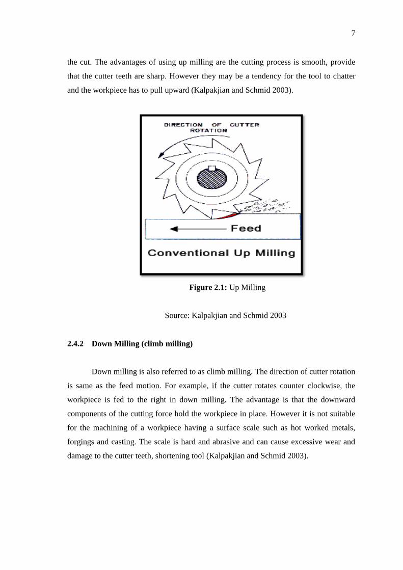
the cut. The advantages of using up milling are the cutting process is smooth, provide
that the cutter teeth are sharp. However they may be a tendency for the tool to chatter
and the workpiece has to pull upward (Kalpakjian and Schmid 2003).
Figure 2.1: Up Milling
Source: Kalpakjian and Schmid 2003
2.4.2 Down Milling (climb milling)
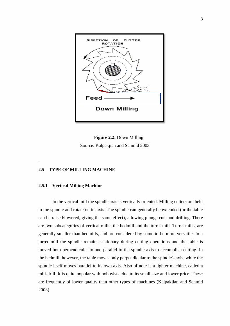
Down milling is also referred to as climb milling. The direction of cutter rotation
is same as the feed motion. For example, if the cutter rotates counter clockwise, the
workpiece is fed to the right in down milling. The advantage is that the downward
components of the cutting force hold the workpiece in place. However it is not suitable
for the machining of a workpiece having a surface scale such as hot worked metals,
forgings and casting. The scale is hard and abrasive and can cause excessive wear and
damage to the cutter teeth, shortening tool (Kalpakjian and Schmid 2003).
8
Figure 2.2: Down Milling
Source: Kalpakjian and Schmid 2003
.
2.5 TYPE OF MILLING MACHINE
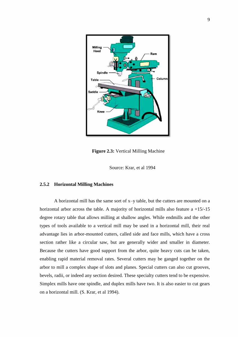
2.5.1 Vertical Milling Machine
In the vertical mill the spindle axis is vertically oriented. Milling cutters are held
in the spindle and rotate on its axis. The spindle can generally be extended (or the table
can be raised/lowered, giving the same effect), allowing plunge cuts and drilling. There
are two subcategories of vertical mills: the bedmill and the turret mill. Turret mills, are
generally smaller than bedmills, and are considered by some to be more versatile. In a
turret mill the spindle remains stationary during cutting operations and the table is
moved both perpendicular to and parallel to the spindle axis to accomplish cutting. In
the bedmill, however, the table moves only perpendicular to the spindle's axis, while the
spindle itself moves parallel to its own axis. Also of note is a lighter machine, called a
mill-drill. It is quite popular with hobbyists, due to its small size and lower price. These
are frequently of lower quality than other types of machines (Kalpakjian and Schmid
2003).
9
Figure 2.3: Vertical Milling Machine
Source: Krar, et al 1994
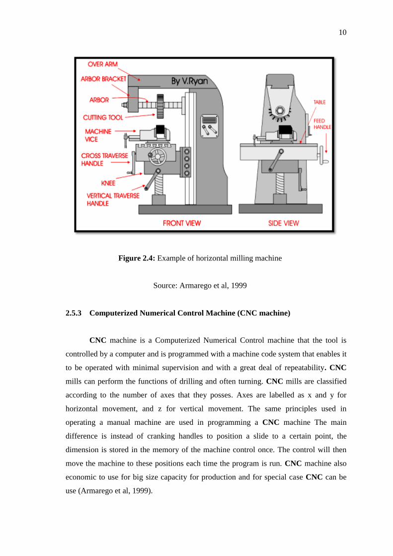
2.5.2 Horizontal Milling Machines
A horizontal mill has the same sort of x–y table, but the cutters are mounted on a
horizontal arbor across the table. A majority of horizontal mills also feature a +15/-15
degree rotary table that allows milling at shallow angles. While endmills and the other
types of tools available to a vertical mill may be used in a horizontal mill, their real
advantage lies in arbor-mounted cutters, called side and face mills, which have a cross
section rather like a circular saw, but are generally wider and smaller in diameter.
Because the cutters have good support from the arbor, quite heavy cuts can be taken,
enabling rapid material removal rates. Several cutters may be ganged together on the
arbor to mill a complex shape of slots and planes. Special cutters can also cut grooves,
bevels, radii, or indeed any section desired. These specialty cutters tend to be expensive.
Simplex mills have one spindle, and duplex mills have two. It is also easier to cut gears
on a horizontal mill. (S. Krar, et al 1994).
10
Figure 2.4: Example of horizontal milling machine
Source: Armarego et al, 1999
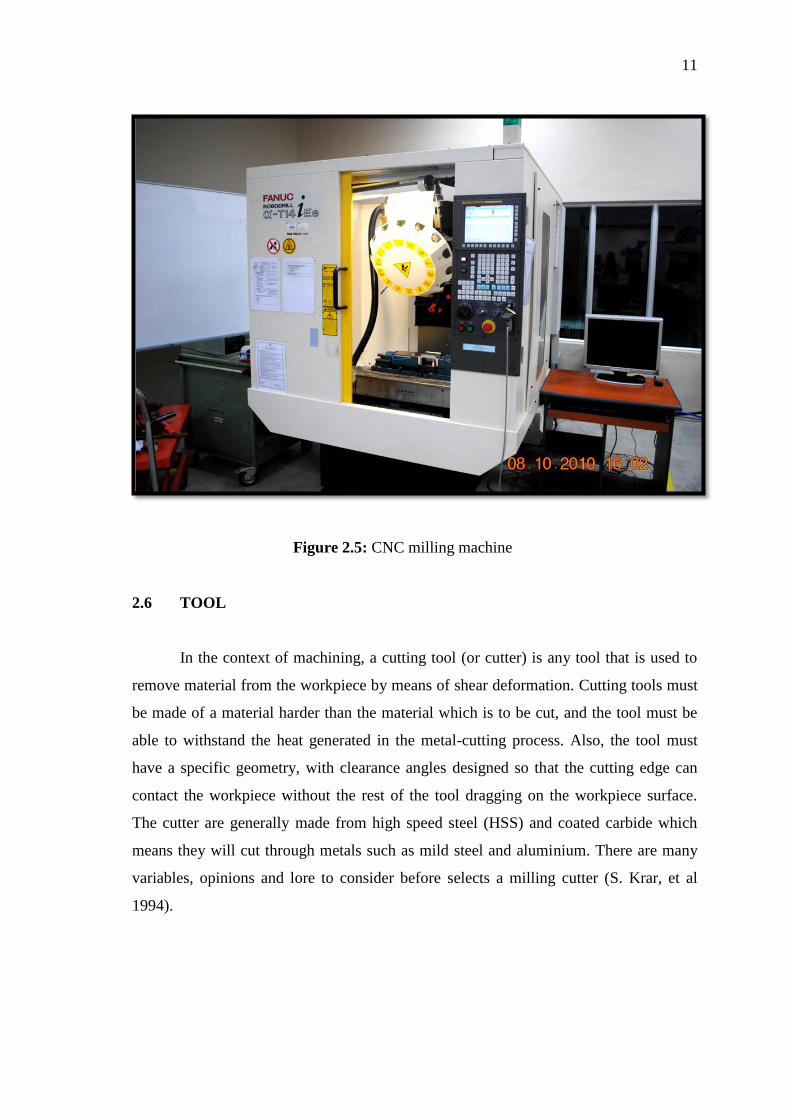
2.5.3 Computerized Numerical Control Machine (CNC machine)
CNC machine is a Computerized Numerical Control machine that the tool is
controlled by a computer and is programmed with a machine code system that enables it
to be operated with minimal supervision and with a great deal of repeatability. CNC
mills can perform the functions of drilling and often turning. CNC mills are classified
according to the number of axes that they posses. Axes are labelled as x and y for
horizontal movement, and z for vertical movement. The same principles used in
operating a manual machine are used in programming a CNC machine The main
difference is instead of cranking handles to position a slide to a certain point, the
dimension is stored in the memory of the machine control once. The control will then
move the machine to these positions each time the program is run. CNC machine also
economic to use for big size capacity for production and for special case CNC can be
use (Armarego et al, 1999).
11
Figure 2.5: CNC milling machine
2.6 TOOL
In the context of machining, a cutting tool (or cutter) is any tool that is used to
remove material from the workpiece by means of shear deformation. Cutting tools must
be made of a material harder than the material which is to be cut, and the tool must be
able to withstand the heat generated in the metal-cutting process. Also, the tool must
have a specific geometry, with clearance angles designed so that the cutting edge can
contact the workpiece without the rest of the tool dragging on the workpiece surface.
The cutter are generally made from high speed steel (HSS) and coated carbide which
means they will cut through metals such as mild steel and aluminium. There are many
variables, opinions and lore to consider before selects a milling cutter (S. Krar, et al
1994).
12
2.6.1 Tool Material
Various cutting-tool materials with a wide range of mechanical, physical, and
chemical properties have been developed over the years. The desirable tool-material
characteristics are chosen based on the criteria below:
(i) Hardness and strength are important with regard to the hardness and strength of
the workpiece material to be machined.
(ii) Impact strength is important in making interrupted cuts in machining, such as
milling.
(iii) Melting temperature of the tool material is important versus the temperatures
developed in the cutting zone.
(iv) The physical properties of thermal conductivity and coefficient of thermal
expansion are important in determining the resistance of the tool materials to
thermal fatigue and shock.
Tool materials generally are divided into the following categories, including:
(i) High-speed steels
(ii) Cast-cobalt alloys
(iii)Carbides
(iv) Coated tools
(v) Alumina-based ceramics
(vi) Cubic boron nitride