Embed Size (px)
Citation preview
7/15/2019 Optimization of Tool Wear in End Milling
http://slidepdf.com/reader/full/optimization-of-tool-wear-in-end-milling 1/73
OPTIMISATION OF TOOL WEAR IN END MILLING
DEPARTMENT OF MECHANICAL ENGINEERING ,CMRCET Page 1
CONTENTS
Chapter name page no
Chapter-1........................................................................................................
1.1 Introduction..............................................................................................
1.2 Types of milling machines.......................................................................
1.3 Types of milling cutters...........................................................................
1.4 End milling cutter.....................................................................................
1.5 Adjustable cutting factors in milling......................................................
1.6 Tool geometry of milling cutters..............................................................
Chapter-2........................................................................................................
2. Literature review.......................................................................................
Chapter-3.........................................................................................................
3.1 Classification of tool materials.................................................................
3.2 Types of tool failure...................................................................................
3.3 Basic wear mechanisms..............................................................................
3.4 Factors involved in tool life.......................................................................
3.5 Tool deformations.....................................................................................
Chapter-4..........................................................................................................
4 .1 Introduction to dampers................................................................................
4.1.1 Use cutters with few inserts......................................................................
4.1.2 Optimize inserts geometry.........................................................................

7/15/2019 Optimization of Tool Wear in End Milling
http://slidepdf.com/reader/full/optimization-of-tool-wear-in-end-milling 2/73
OPTIMISATION OF TOOL WEAR IN END MILLING
DEPARTMENT OF MECHANICAL ENGINEERING ,CMRCET Page 2
4.1.3 Choose inserts coatings carefully..............................................................
4.2 End mill cutter damper geometry..................................................................
Chapter-5.............................................................................................................
5.1 Equipment used............................................................................................
5.1.1Vertical milling machine............................................................................
5.2 Cutting tools used..........................................................................................
5.2.1Cutting tool material...................................................................................
5.3.1 Collet..........................................................................................................
5.4. Work piece material....................................................................................
5.4.1Aluminum....................................................................................................
5.5Work piece holding device.............................................................................
5.5.1Bench vice...................................................................................................
5.6 Measuring instruments..................................................................................
5.6.1 Tool maker microscope...............................................................................
5.6.2 Stop watch..................................................................................................
Chapter-6..............................................................................................................
6.1 Defination of anova.........................................................................................
6.2 Purpose............................................................................................................
6.3 Types of anova................................................................................................
6.4 Taguchi design................................................................................................
6.5 Introduction to Taguchi design......................................................................
6.5.1 Trail and error method.................................................................................
6.5.2 Design of experiment................................................................................
7/15/2019 Optimization of Tool Wear in End Milling
http://slidepdf.com/reader/full/optimization-of-tool-wear-in-end-milling 3/73
OPTIMISATION OF TOOL WEAR IN END MILLING
DEPARTMENT OF MECHANICAL ENGINEERING ,CMRCET Page 3
6.6 Taguchi design..............................................................................................
6.7 Taguchi method treats optimization problems in two categories…………
6.7.1 Static problem………………………………………………………….
6.7.2 Dynamic problem......................................................................................
6.8 Types of static problem s/n ratio’s................................................................
6.9 Types of dynamic problem s/n ratio’s...........................................................
6.10 8 – Steps of Taguchi methodology...............................................................
6.11 Signal to Noise s/n ratio.............................................................................
6.12 Static v/s dynamic s/n ratio........................................................................
Chapter-7 design of experiments..................................................................
7.1 Taguchi design method................................................................................
7.2 Experimental setup and conditions...............................................................
7.3 Experimental design.....................................................................................
7.3.1Orthogonal arry and experimental factors.................................................
7.3.2 Experimental set up and procedure...........................................................
7.4 Results and discussions................................................................................
7.5 Regression analysis.......................................................................................
Conclusion..........................................................................................................
References............................................................................................................
7/15/2019 Optimization of Tool Wear in End Milling
http://slidepdf.com/reader/full/optimization-of-tool-wear-in-end-milling 4/73
OPTIMISATION OF TOOL WEAR IN END MILLING
DEPARTMENT OF MECHANICAL ENGINEERING ,CMRCET Page 4
ABSTRACT
Milling is one of the machining process and one of the most widely used metal
removal processes in industry. Cutting action in milling operation is different from other
operation. With the cutting tool rotating, work piece moves in feed direction. In milling
multipoint cutting tool used. Milled surfaces are largely used to mate with other parts in die,
aero space, automotive, and machinery design as well as in manufacturing industries. Long
end mills, the most widely used tool in high speed machining operations, undergo a bending
vibration similar to a cantilevered structure during machining. Sensing of tool wear and
breaking in machining is important for the manufacturing processes.
In this project, the tool wear area was considered as the criterion that would affect the
result of cutting process. Tool wear and breakage detection systems are typically based on
force acoustic emission and temperature in milling process. In the present project, an attempt
is made to understand the influence of cutting speed, feed and depth of cut on tool wear of the
end milling cutter. This project studies the application of Taguchi design to optimize tool
wear in end milling. ANOVA analysis is carried out to identify the significant characters
affecting tool wear
7/15/2019 Optimization of Tool Wear in End Milling
http://slidepdf.com/reader/full/optimization-of-tool-wear-in-end-milling 5/73
OPTIMISATION OF TOOL WEAR IN END MILLING
DEPARTMENT OF MECHANICAL ENGINEERING ,CMRCET Page 5
Chapter-1
INTRODUCTION
Milling machines were first invented and developed by Eli Whitney to mass produce
interchangeable musket parts. Although crude, these machines assisted man in maintaining
accuracy and uniformity while duplicating parts that could not be manufactured with the use
of a file.Development and improvements of the milling machine and components
Continued, which resulted in the manufacturing of heavier Arbors and high speed steel and
carbide cutters. These components allowed the operator to remove metal faster, and with
more accuracy, than previous machines. Variations of milling machines were also developed
to perform special milling operations. During this era, computerized machines have been
developed to alleviate errors and provide better quality in the finished product
Milling is the most common form of machining, a material removal process, which
can create a variety of features on a part by cutting away the unwanted material. The milling
process requires a milling machine, work piece, fixture, and cutter. The work piece is a piece
of pre-shaped material that is secured to the fixture, which itself is attached to a platform
inside the milling machine. The cutter is a cutting tool with sharp teeth that is also secured in
the milling machine and rotates at high speeds. By feeding the work piece into the rotating
cutter, material is cut away from this work piece in the form of small chips to create the
desiredshape.
Milling is typically used to produce parts that are not axially symmetric and have
many features, such as holes, slots, pockets, and even three dimensional surface contours.
Parts that are fabricated completely through milling often include components that are used in
limited quantities, perhaps for prototypes, such as custom designed fasteners or brackets.
Another application of milling is the fabrication of tooling for other processes. For example,
three-dimensional molds are typically milled. Milling is also commonly used as a secondary
7/15/2019 Optimization of Tool Wear in End Milling
http://slidepdf.com/reader/full/optimization-of-tool-wear-in-end-milling 6/73
OPTIMISATION OF TOOL WEAR IN END MILLING
DEPARTMENT OF MECHANICAL ENGINEERING ,CMRCET Page 6
process to add or refine features on parts that were manufactured using a different process.
Due to the high tolerances and surface finishes that milling can offer, it is ideal for adding
precision features to a part whose basic shape has already been formed.
1.1 Types of Milling Machine
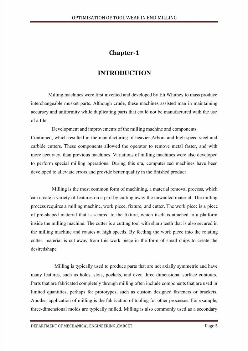
1.1.1 Vertical milling machine
Fig 1.1Vertical milling machine
This study guide will cover the major working parts, functions, and machining
techniques that can be found used on most vertical milling machines. This study guide has
been designed to directly represent the questions that will be found on the open book written
assessment and as an aid for the hands-on usability assessment. Both assessments will also
include questions related to standard machine shop safety and APS internal user safety
guidelines. Answering the questions found at the end of the study guide will enable the user to successfully pass the hands-on usability and open book written assessments. Study guide
7/15/2019 Optimization of Tool Wear in End Milling
http://slidepdf.com/reader/full/optimization-of-tool-wear-in-end-milling 7/73
OPTIMISATION OF TOOL WEAR IN END MILLING
DEPARTMENT OF MECHANICAL ENGINEERING ,CMRCET Page 7
practice test and answers can be found at the end of the guide. The Milling Machine uses a
rotating milling cutter to produce machined surfaces by progressively removing material
from a work piece. The vertical milling machine also can function like a drill press because
the spindle is perpendicular to the table and can be lowered into the work piece
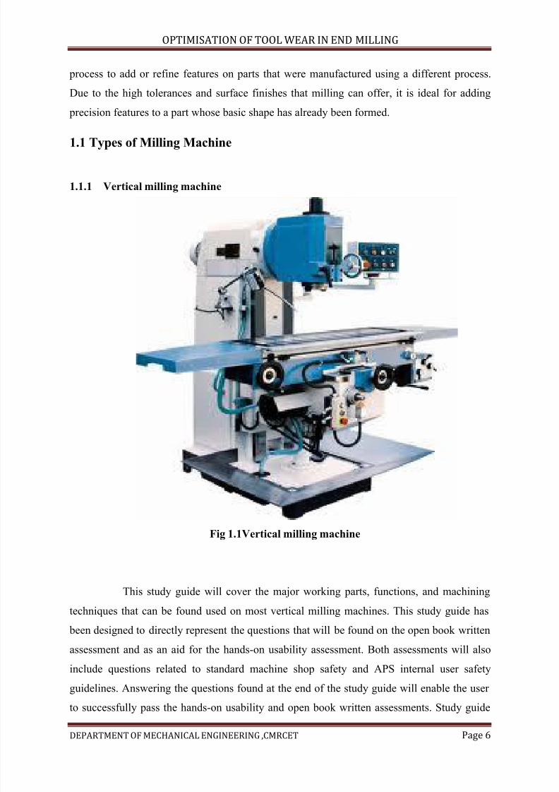
1.1.2 Horizontal milling machine
Fig1.2 Horizontal milling machine
Horizontal milling machine is provided with horizontal spindle, parallel to the work
piece or job .this machine comprises a vertical column in corporate with an over arm, to
support arbour free end which carries a cutting tool. Operating the horizontal milling machine
is not much different than operating the vertical milling machine until you begin using the
over-arm supports and arbor driven cutters. When we use the horizontal milling machine in
this way, a new set of operating principles need to be addressed. In the information that
follows please pay close attention to the details. The information will help you not only make
better parts and keep the machine running in proper order, but it may also keep you from
getting seriously injured.
7/15/2019 Optimization of Tool Wear in End Milling
http://slidepdf.com/reader/full/optimization-of-tool-wear-in-end-milling 8/73
OPTIMISATION OF TOOL WEAR IN END MILLING
DEPARTMENT OF MECHANICAL ENGINEERING ,CMRCET Page 8
1.2 Types of milling cutter
1. Plain milling cutter
2. Side milling cutter
3. Metal slitting saw
4. Angle milling cutters
5. End milling cutters
6. T-slot milling cutters
7. Slot drill
8. Fly cutter
9. Woodruff key slot miller cutter
10. Form milling cutter
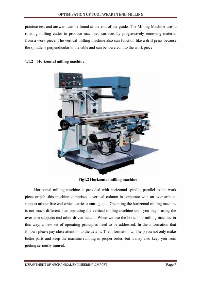
1.3 End milling cutter:
Fig 1.3 End mill cutters
7/15/2019 Optimization of Tool Wear in End Milling
http://slidepdf.com/reader/full/optimization-of-tool-wear-in-end-milling 9/73
OPTIMISATION OF TOOL WEAR IN END MILLING
DEPARTMENT OF MECHANICAL ENGINEERING ,CMRCET Page 9
These milling cutters have teeth on the periphery as well as on the end face. It is used
for machining both horizontal and vertical surfaces. It is employed for milling slots, key
ways, grooves and irregular shaped surfaces. They are sub divided into,
a) Shank type milling cutter:
It may be taper shank or straight shank. Taper shank confirm to the morse taper and is
directly secured in the spindle nose whereas, straight shanks are held in a spring collets
b) Shell end milling cutters:
It has a central hole for mounting on arbour and made without shank. They are large
and heavier compared to other types of end mills. It carries teeth on its periphery and on end
face. They are available for the diameter ranging from 50 to 160 mm and width from 32 to 63
mm. The teeth may be straight or helical.
1.4 Adjustable cutting factors in milling:
The three primary factors in any basic turning operation are speed, feed, and depth of
cut. Other factors such as kind of material and type of tool have a large influence, of course,
but these three are the ones the operator can change by adjusting the controls, right at themachine.
Speed:
Speed always refers to the spindle and the work piece. When it is stated in revolutions
per minute (rpm) it tells their rotating speed. But the important feature for a particular turning
operation is the surface speed, or the speed at which the work piece material is moving past
the cutting tool. It is simply the product of the rotating speed times the circumference of the
work piece before the cut is started. It is expressed in meter per minute (m/min), and it refers
only to the work piece. Every different diameter on a work piece will have a different cutting
speed, even though the rotating speed remains the same. Min 1 1000
V DN m π − = Here, v is the cutting speed in turning, Dis the initial diameter of the work
piece in mm, and N is the spindle speed in RPM.
7/15/2019 Optimization of Tool Wear in End Milling
http://slidepdf.com/reader/full/optimization-of-tool-wear-in-end-milling 10/73
OPTIMISATION OF TOOL WEAR IN END MILLING
DEPARTMENT OF MECHANICAL ENGINEERING ,CMRCET Page 10
Feed:
Feed always refers to the cutting tool, and it is the rate at which the tool advances
along its cutting path. On most power-fed lathes, the feed rate is directly related to the spindle
speed and is expressed in mm (of tool advance) per revolution (of the spindle), or mm/rev. .
.min 1 m F = f N mm − Here, m F is the feed in mm per minute, f is the feed in mm/rev and
N is the spindle speed in RPM.3
Depth of Cut
Depth of cut is practically self explanatory. It is the thickness of the layer being
removed (in a single pass) from the work piece or the distance from the uncut surface of the
work to the cut surface, expressed in mm. It is important to note, though, that the diameter of
the work piece is reduced by two times the depth of cut because this layer is being removed
from both sides of the work. Cut 2 d D d mm −=Here, Dand d represent initial and final
diameter (in mm) of the job respectively.
1.5 Tool geometry of milling cutters:
7/15/2019 Optimization of Tool Wear in End Milling
http://slidepdf.com/reader/full/optimization-of-tool-wear-in-end-milling 11/73
OPTIMISATION OF TOOL WEAR IN END MILLING
DEPARTMENT OF MECHANICAL ENGINEERING ,CMRCET Page 11
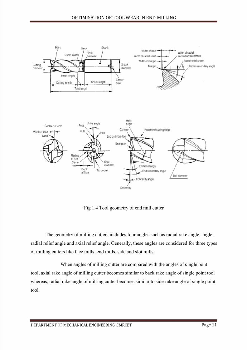
Fig 1.4 Tool geometry of end mill cutter
The geometry of milling cutters includes four angles such as radial rake angle, angle,
radial relief angle and axial relief angle. Generally, these angles are considered for three typesof milling cutters like face mills, end mills, side and slot mills.
When angles of milling cutter are compared with the angles of single pont
tool, axial rake angle of milling cutter becomes similar to back rake angle of single point tool
whereas, radial rake angle of milling cutter becomes similar to side rake angle of single point
tool.
7/15/2019 Optimization of Tool Wear in End Milling
http://slidepdf.com/reader/full/optimization-of-tool-wear-in-end-milling 12/73
OPTIMISATION OF TOOL WEAR IN END MILLING
DEPARTMENT OF MECHANICAL ENGINEERING ,CMRCET Page 12
Radial rake angle:
The angle measured between the slide face and the radial plane passing through the
cutter axis is reffered as radial rake angle. Radial rake angle can be positive or negative.
Angle makes the cutting edge more stronger.
Axial rake angle:
Axial rake angle is the cutting edge inclination with respect to cutter axis. It also gives
the direction of chips flow. Axial rake angle can positive or negative.
Positive axial rake angle removes the chips away from the cut when rake nose of
cutter contacts with the workpiece while negative axial rake angle traverse the chips along thedirection of work piece. It also makes the cutting edge morestronger
Mostly negative axial rake angle is applied in carbide cutters.
Approach angle:
The angle measured between the plane normal to axial cutter and the plane tangent to
the surface of revolution of thecutting edge is reffered as approach angle.
The value of approach angle is different for different types of milling cutters.
Side clearance angle:
The angle measured between the cut surface and the clearance flank on the cutter is
reffered as side clearance angle. The cutting edges becomes weak at higher clearance, but less
wear and tear occurs. Its value rely on the end mill diameter.
7/15/2019 Optimization of Tool Wear in End Milling
http://slidepdf.com/reader/full/optimization-of-tool-wear-in-end-milling 13/73
OPTIMISATION OF TOOL WEAR IN END MILLING
DEPARTMENT OF MECHANICAL ENGINEERING ,CMRCET Page 13
Chapter-2
Literature review
B. S. Patel [ 1 ] investigated about influence of various machining parameters like tool speed,
tool feed, depth of cut and tool diameter. In the present study, experiments are conducted on
al 6351 – t6 material with four factors and five levels and try to find out optimum surface
roughness by using Taguchi method. This paper attempts to introduce how Taguchi
parameter design could be used in identifying the significant processing parameters and
optimizing the surface roughness of end-milling operations.
In this study, the analysis of confirmation experiments has shown that Taguchi
parameter design can successfully verify the optimum cutting parameters, which are a1 > b4
> c4 > d1 (tool feed (a), tool speed(b), tool diameter(c), depth of cut(d) ). The work piece
material used was al 6351 – t6. The average value of surface roughness [mean (= - 4.44 μm)
and s/n ratio (= 16.1115 db.)] Were calculated and were found to be within the range.
Taguchi parameter design can provide a systematic procedure that can effectively and
efficiently identify the optimum surface roughness in the process control of individual end
milling machines. It also allows industry to reduce process or product variability and
minimize product defects by using a relatively small number of experimental runs and costs
to achieve superior-quality products. This research only demonstrates how to use Taguchi
parameter design for optimizing machining performance with minimum cost. Further study
could consider more factors (e.g. Forces, materials, lubricant, etc.) In the research to see how
the factors would affect surface roughness. Also, further study could consider the outcomes
of Taguchi parameter design when it is implemented as a part of management decision-
making processes.
1. P.S. SIVASAKTHIVEL
Department of mechanical engineering, kumaraguru college of technology
Prediction of tool wear from machining parameters by response surfacemethodology in end milling
7/15/2019 Optimization of Tool Wear in End Milling
http://slidepdf.com/reader/full/optimization-of-tool-wear-in-end-milling 14/73
OPTIMISATION OF TOOL WEAR IN END MILLING
DEPARTMENT OF MECHANICAL ENGINEERING ,CMRCET Page 14
Tool wear increases cutting force, vibration, temperature, etc in end milling and
reduces surface finish of the Machined work piece. Mathematical model has been developed
to predict the tool wear in terms of machining Parameters such as helix angle of cutting tool,
spindle speed, feed rate, axial and radial depth of cut. Central Composite rotatable second
order response surface methodology was employed to create a mathematical model and the
adequacy of the model was verified using analysis of variance. The experiments were
conducted on aluminium Al 6063 by high speed steel end mill cutter and tool wear was
measured using tool maker’s microscope. The direct and interaction effect of the machining
parameter with tool wear were analyzed, which helped to select process Parameter in order to
reduce tool wear which ensures quality of milling.
The following conclusions were arrived from the results of the present investigation.
The investigation presented a central composite rotatable second order response
surface methodology to develop a mathematical model to predict tool wear in terms of helix
angle, spindle speed, feed rate, axial and radial depth of cut. The helix angle is the most
significant parameter which reduces tool wear. The tool wear is minimal in between 400 –
450 helix angles. The increase in spindle speed and axial depth of cut reduces the tool wear.
The decrease in radial depth of cut reduces tool wear. The interactions between the process
parameters were analyzed and strong interactions were observe between helix angle and axial
depth of cut; spindle speed and feed rate; helix angle and feed rate; and spindle speed and
radial depth of cut
3. K. SUNDARA MURTHYI; DR. I. RAJENDRAN
II Jayam College of Engineering and
Technology, Department of Mechanical Engineering, 636 813 Dharmapuri, Tamil Nadu,
India, [email protected]
Optimization of end milling parameters under minimum quantity lubrication using
principal component analysis and grey relational analysis
In his paper, genetic algorithm based artificial neural network hybrid prediction
model is proposed to foretell surface roughness and tool wear. A multiple objective
optimization methodology, by using principal component analysis, grey relational analysis
and Taguchi method is also proposed to optimize the machining parameters of Al 6063 under
maximum quantity lubrication. The following conclusions are made:
7/15/2019 Optimization of Tool Wear in End Milling
http://slidepdf.com/reader/full/optimization-of-tool-wear-in-end-milling 15/73
OPTIMISATION OF TOOL WEAR IN END MILLING
DEPARTMENT OF MECHANICAL ENGINEERING ,CMRCET Page 15
The optimum machining parameters for minimum surface roughness and tool wear
are cutting speed of 88 m/min, feed velocity of 180 mm/min, depth of cut of 1.4 mm and
coolant flow rate of 600 ml/hr. Among the machining parameters: cutting speed, feed
velocity, depth of cut and lubricant flow rate, the cutting speed is the most significant with
percentage contribution of 48.75%, followed by feed velocity with 22.12%, liquid flow rate
with 18.86% and at last depth of cut with 10.26%.
The proposed GA based ANN hybrid prediction model has excellent agreement with
experimental values, with errors of only 3.3%.The validity tests demonstrated that the
proposed multiple objective optimization methodology is able in determining the optimum
machining parameters in end milling
4. J.PRADEEP KUMAR1 K.THIRUMURUGAN2
Address for Correspondence
1Assistant Professor, 2PG Student, Department of Production Engineering, PSG college of
Technology,Coimbatore-641 004
Optimization of machining parameters for Milling titanium using Taguchi method
Titanium alloys have been widely used in industries, especially aerospace industries,
due to their good mechanical and chemical properties. However, machining of titanium alloys
involves expensive tooling cost at the expense of getting good surface roughness. This paper
describes a comprehensive study of end milling of titanium alloys. The study investigated the
optimum parameters that could produce significant good surface roughness whereby reducing
tooling cost. The quality of design can be improved by improving quality and productivity in
company-wide activities. It employed the Taguchi design method to optimize the surface
roughness quality in a computer numerical control end mills. Taguchi’s parameter design is
an important tool for robust design, which offers a simple and systematic approach to
optimize a design for performance, quality and cost. The control parameters were spindle
speed, feed rate, depth of cut and type of end milling tool. Then, an orthogonal array of L27
(313) and analysis of variance (ANOVA) were carried out to identify the significant factors
affecting the surface roughness. The best parameters were chosen based on the signal-to-
noise ratio (SNR).The experimental results indicated that the most significant factors
affecting the surface roughness of titanium alloy during end milling process were primarily
7/15/2019 Optimization of Tool Wear in End Milling
http://slidepdf.com/reader/full/optimization-of-tool-wear-in-end-milling 16/73
OPTIMISATION OF TOOL WEAR IN END MILLING
DEPARTMENT OF MECHANICAL ENGINEERING ,CMRCET Page 16
the spindle speed used, secondly, the type of cutting tool used, thirdly, the feed rate chosen
and lastly, the depth of cut chosen.
From the findings of the following can be concluded;
Taguchi’s robust design method is suitable to optimize the surface roughness in
milling CP Ti Grade 2. The significant factors for the surface roughness in milling CP Ti
Grade 2 were the spindle speed and the tool grade, with contribution of 30.347 and 29.933
respectively.
The optimal condition for surface roughness in milling CP Ti Grade 2 was resulted
at spindle speed of 2500 rpm, feed rate of 300, depth of cut 0.3 and solid carbide end mill
cutter.
The optimal interaction parameter was between the spindle speed and feed rate at level 3.
Chapter-3
TOOL MATERIALS AND WEAR OF CUTTING TOOLS
3.1 Classification of tool materials
The several tool materials in use today may be classified as follows:
1. Carbon steels
2. Medium alloy steels
7/15/2019 Optimization of Tool Wear in End Milling
http://slidepdf.com/reader/full/optimization-of-tool-wear-in-end-milling 17/73
OPTIMISATION OF TOOL WEAR IN END MILLING
DEPARTMENT OF MECHANICAL ENGINEERING ,CMRCET Page 17
3. High speed steels
4. Cast tool alloys
5. Cemented carbides
6. Minerals
a. Silicon carbide
b. Aluminum oxide
c. Diamond
While the first three groups of materials are really steels in as much as their major
constituents iron, the latter three groups contain iron as an impurity.
3.1.1 Carbon tool steels:
Tools in use before 1900 were all of this type. Their chief characteristics are low hot
hardeners and poor hard-enability. They are usually quenched into brine and even then only a
thin layer can be fully hardened with the attendant risk of developing quenching cracks. The
carbon steels are limited in use to tools of small section which operate at relatively low speed
(and hence low temperature)
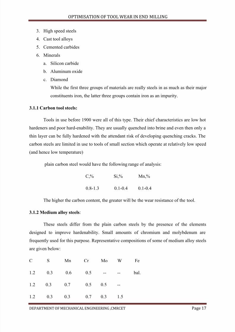
plain carbon steel would have the following range of analysis:
C,% Si,% Mn,%
0.8-1.3 0.1-0.4 0.1-0.4
The higher the carbon content, the greater will be the wear resistance of the tool.
3.1.2 Medium alloy steels:
These steels differ from the plain carbon steels by the presence of the elements
designed to improve hardenability. Small amounts of chromium and molybdenum are
frequently used for this purpose. Representative compositions of some of medium alloy steels
are given below:
C S Mn Cr Mo W Fe
1.2 0.3 0.6 0.5 -- -- bal.
1.2 0.3 0.7 0.5 0.5 --
1.2 0.3 0.3 0.7 0.3 1.5
7/15/2019 Optimization of Tool Wear in End Milling
http://slidepdf.com/reader/full/optimization-of-tool-wear-in-end-milling 18/73
OPTIMISATION OF TOOL WEAR IN END MILLING
DEPARTMENT OF MECHANICAL ENGINEERING ,CMRCET Page 18
1.3 0.3 0.3 0.7 -- 4.0
Upto about 4% of tungsten is sometimes added to these steels in order to improve
their wear resistance. While these steels are widely used for drills,taps and reamers,their hot
hardness is about the same as that of carbon steels, and they are not satisfactory for high
speed turning or milling.
3.1.3 High speed steels:
This material was first used for tuning tools by taylor and white about the turn of the
century. Its introduction made possible a significant increase in machining speeds,which
accounts for its name. However, today high speed steel is misnamed since it is now the
general purpose material for use in machining operations performed at low or moderate
speeds. The chief characteristic of these steels is superior hot hardness and wear resistance.
The compositions of three popular high speed steels are given below:
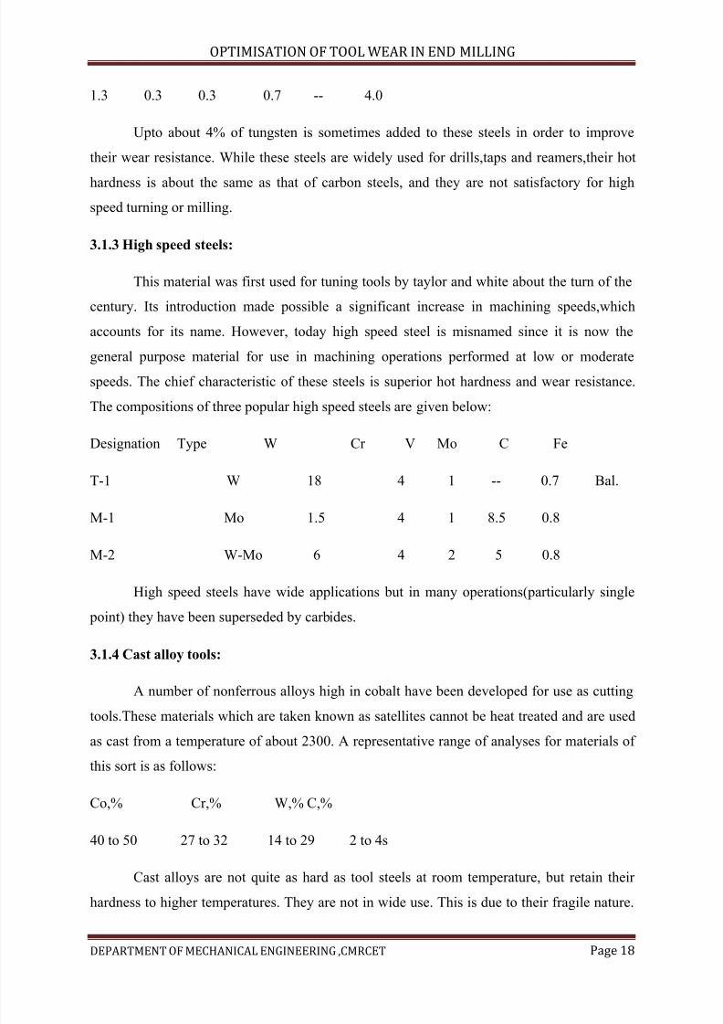
Designation Type W Cr V Mo C Fe
T-1 W 18 4 1 -- 0.7 Bal.
M-1 Mo 1.5 4 1 8.5 0.8
M-2 W-Mo 6 4 2 5 0.8
High speed steels have wide applications but in many operations(particularly single
point) they have been superseded by carbides.
3.1.4 Cast alloy tools:
A number of nonferrous alloys high in cobalt have been developed for use as cutting
tools.These materials which are taken known as satellites cannot be heat treated and are used
as cast from a temperature of about 2300. A representative range of analyses for materials of
this sort is as follows:
Co,% Cr,% W,% C,%
40 to 50 27 to 32 14 to 29 2 to 4s
Cast alloys are not quite as hard as tool steels at room temperature, but retain their
hardness to higher temperatures. They are not in wide use. This is due to their fragile nature.
7/15/2019 Optimization of Tool Wear in End Milling
http://slidepdf.com/reader/full/optimization-of-tool-wear-in-end-milling 19/73
OPTIMISATION OF TOOL WEAR IN END MILLING
DEPARTMENT OF MECHANICAL ENGINEERING ,CMRCET Page 19
Like all cast materials these alloys are relatively weak in tension and hence tend to shatter
when subjected to a shock load or if not properly supported.
3.1.5 Cemented carbides:
Carbides can be classified into two types:
1. The C grade (straight carbides) consisting of tungsten carbide with cobalt as a
binder for use in machining cast iron and nonferrous metals.
2. The S grade (steel cutting carbides) consisting of tungsten, titanium and
tanlabim carbides with a cobalt binder for using machining steels.
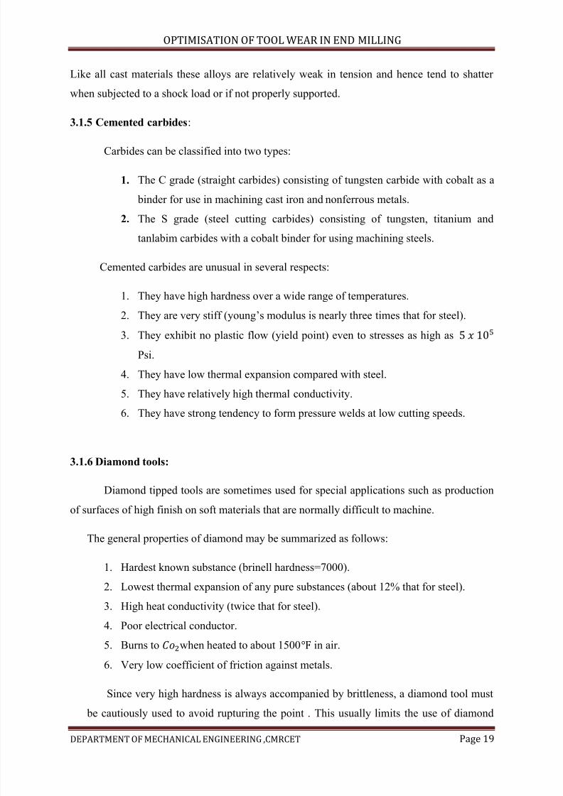
Cemented carbides are unusual in several respects:
1. They have high hardness over a wide range of temperatures.
2. They are very stiff (young’s modulus is nearly three times that for steel).
3. They exhibit no plastic flow (yield point) even to stresses as high as
Psi.
4. They have low thermal expansion compared with steel.
5. They have relatively high thermal conductivity.
6. They have strong tendency to form pressure welds at low cutting speeds.
3.1.6 Diamond tools:
Diamond tipped tools are sometimes used for special applications such as production
of surfaces of high finish on soft materials that are normally difficult to machine.
The general properties of diamond may be summarized as follows:
1. Hardest known substance (brinell hardness=7000).
2. Lowest thermal expansion of any pure substances (about 12% that for steel).
3. High heat conductivity (twice that for steel).
4. Poor electrical conductor.
5. Burns to when heated to about 1500 in air.
6. Very low coefficient of friction against metals.
Since very high hardness is always accompanied by brittleness, a diamond tool must be cautiously used to avoid rupturing the point . This usually limits the use of diamond
7/15/2019 Optimization of Tool Wear in End Milling
http://slidepdf.com/reader/full/optimization-of-tool-wear-in-end-milling 20/73
OPTIMISATION OF TOOL WEAR IN END MILLING
DEPARTMENT OF MECHANICAL ENGINEERING ,CMRCET Page 20
tools to light continuous cuts in relatively soft metals, and low values of rake angle are
normally used to provide a cutting edge.
3.2 Types of tool failure
The failure of cutting tools may be classified in three general types
3.2.1. Temperature failure:
The hardness (and strength) of a tool varies with temperature. When the rate of energy
input to the tip of a tool becomes too large, the tool becomes too soft to function properly and
failure ensues. This type of failure occurs quite rapidly, is frequently accompanied by
sparking, and is easily recognized.
3 .2.2.Rupture of tool point:
Because of high hardness required, the tip of a cutting tool is mechanically weak and
brittle. This is particularly true of carbide and diamond tipped tools. Whenever the cutting
forces exceed a critical value for a given tool, small portions of the cutting edge begin to chip
off, or the entire tip may break away in one piece. The high forces which produce this type of
failure are not generally associated with steady state cutting, but rather with variations in the
cutting process such as might obtain in milling operation or when cutting with excessive
vibration(chatter). For a given tool material, the tendency toward a rupture failure can be
diminished either by reducing the casual forces, redirecting them, or redesigning the tool to
withstand them. The forces can frequently be diminished by increasing the rigidity of the tool
and work holders.
3.2.3 .Gradual wear at the tool point:
When a tool has been in use for some time, wear may become evident in two regions
as indicated in fig. 2-1 (i.e. On the flank and faces of the cutting tool). In some cases the flank
wear is by no means uniform as indicated in fig. 2-1(b). Nose grooving is a common form of
during wear high speed finishing operations, while notching occurs when machining high
strength material, particularly heavily work hardening material such as stainless steel, Ni and
Co base alloys. Both crater and flank wear (including nose grooving and notch) are
progressive with time as indicated in fig.2-2(a) and 2-2(b). At high metal removal rates nose
grooving and notch wear may be severely modified due to oxidation.
7/15/2019 Optimization of Tool Wear in End Milling
http://slidepdf.com/reader/full/optimization-of-tool-wear-in-end-milling 21/73
OPTIMISATION OF TOOL WEAR IN END MILLING
DEPARTMENT OF MECHANICAL ENGINEERING ,CMRCET Page 21
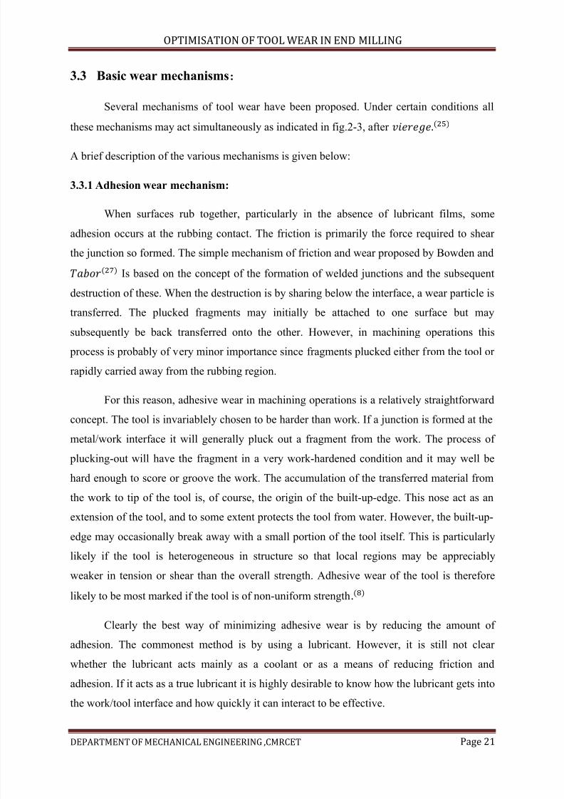
3.3 Basic wear mechanisms:
Several mechanisms of tool wear have been proposed. Under certain conditions all
these mechanisms may act simultaneously as indicated in fig.2-3, after
A brief description of the various mechanisms is given below:
3.3.1 Adhesion wear mechanism:
When surfaces rub together, particularly in the absence of lubricant films, some
adhesion occurs at the rubbing contact. The friction is primarily the force required to shear
the junction so formed. The simple mechanism of friction and wear proposed by Bowden and
Is based on the concept of the formation of welded junctions and the subsequent
destruction of these. When the destruction is by sharing below the interface, a wear particle is
transferred. The plucked fragments may initially be attached to one surface but may
subsequently be back transferred onto the other. However, in machining operations this
process is probably of very minor importance since fragments plucked either from the tool or
rapidly carried away from the rubbing region.
For this reason, adhesive wear in machining operations is a relatively straightforward
concept. The tool is invariablely chosen to be harder than work. If a junction is formed at the
metal/work interface it will generally pluck out a fragment from the work. The process of
plucking-out will have the fragment in a very work-hardened condition and it may well be
hard enough to score or groove the work. The accumulation of the transferred material from
the work to tip of the tool is, of course, the origin of the built-up-edge. This nose act as an
extension of the tool, and to some extent protects the tool from water. However, the built-up-
edge may occasionally break away with a small portion of the tool itself. This is particularly
likely if the tool is heterogeneous in structure so that local regions may be appreciablyweaker in tension or shear than the overall strength. Adhesive wear of the tool is therefore
likely to be most marked if the tool is of non-uniform strength
Clearly the best way of minimizing adhesive wear is by reducing the amount of
adhesion. The commonest method is by using a lubricant. However, it is still not clear
whether the lubricant acts mainly as a coolant or as a means of reducing friction and
adhesion. If it acts as a true lubricant it is highly desirable to know how the lubricant gets into
the work/tool interface and how quickly it can interact to be effective.
7/15/2019 Optimization of Tool Wear in End Milling
http://slidepdf.com/reader/full/optimization-of-tool-wear-in-end-milling 22/73
OPTIMISATION OF TOOL WEAR IN END MILLING
DEPARTMENT OF MECHANICAL ENGINEERING ,CMRCET Page 22
Another approach is to allow adhesion to occur but to ensure that transferred film is
very easy to shear. The easiest way of doing this is to incorporate suitable materials on small
quantities in the work material itself. It may be that free-machining steel, which contains
small quantities of lead, function, to some extent, in this way. Another idea is to make the
work relatively brittle so that the removed chip easily fragments and breaks away from the
tool face. Silicates in the work probably function in this way, although at higher speeds it is
possible that a smeared glass-like film acts, in some measure, as a lubricant between work
and tool.
This mechanism cannot be the complete explanation of the wear process, since it
implies that one surface will become covered with a layer of metal from the other surface and
it does nor explain how loose wear particles are produced.
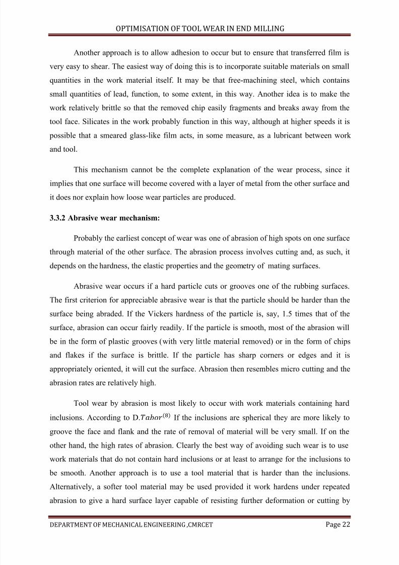
3.3.2 Abrasive wear mechanism:
Probably the earliest concept of wear was one of abrasion of high spots on one surface
through material of the other surface. The abrasion process involves cutting and, as such, it
depends on the hardness, the elastic properties and the geometry of mating surfaces.
Abrasive wear occurs if a hard particle cuts or grooves one of the rubbing surfaces.
The first criterion for appreciable abrasive wear is that the particle should be harder than the
surface being abraded. If the Vickers hardness of the particle is, say, 1.5 times that of the
surface, abrasion can occur fairly readily. If the particle is smooth, most of the abrasion will
be in the form of plastic grooves (with very little material removed) or in the form of chips
and flakes if the surface is brittle. If the particle has sharp corners or edges and it is
appropriately oriented, it will cut the surface. Abrasion then resembles micro cutting and the
abrasion rates are relatively high.
Tool wear by abrasion is most likely to occur with work materials containing hard
inclusions. According to D. If the inclusions are spherical they are more likely to
groove the face and flank and the rate of removal of material will be very small. If on the
other hand, the high rates of abrasion. Clearly the best way of avoiding such wear is to use
work materials that do not contain hard inclusions or at least to arrange for the inclusions to
be smooth. Another approach is to use a tool material that is harder than the inclusions.
Alternatively, a softer tool material may be used provided it work hardens under repeated
abrasion to give a hard surface layer capable of resisting further deformation or cutting by
7/15/2019 Optimization of Tool Wear in End Milling
http://slidepdf.com/reader/full/optimization-of-tool-wear-in-end-milling 23/73
OPTIMISATION OF TOOL WEAR IN END MILLING
DEPARTMENT OF MECHANICAL ENGINEERING ,CMRCET Page 23
coating the tool with a very hard skin either by plating or by chemical treatment, e.g.
Nitriding.
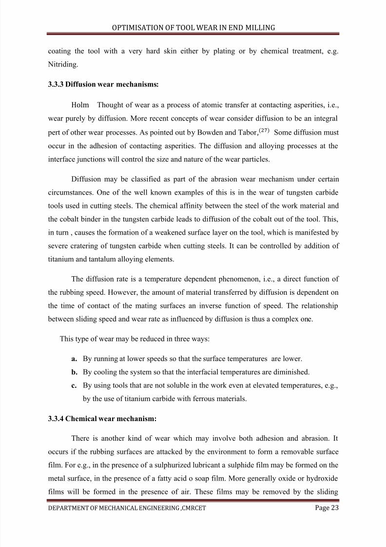
3.3.3 Diffusion wear mechanisms:
Thought of wear as a process of atomic transfer at contacting asperities, i.e.,
wear purely by diffusion. More recent concepts of wear consider diffusion to be an integral
pert of other wear processes. As pointed out by Bowden and Tabor Some diffusion must
occur in the adhesion of contacting asperities. The diffusion and alloying processes at the
interface junctions will control the size and nature of the wear particles.
Diffusion may be classified as part of the abrasion wear mechanism under certain
circumstances. One of the well known examples of this is in the wear of tungsten carbide
tools used in cutting steels. The chemical affinity between the steel of the work material and
the cobalt binder in the tungsten carbide leads to diffusion of the cobalt out of the tool. This,
in turn , causes the formation of a weakened surface layer on the tool, which is manifested by
severe cratering of tungsten carbide when cutting steels. It can be controlled by addition of
titanium and tantalum alloying elements.
The diffusion rate is a temperature dependent phenomenon, i.e., a direct function of
the rubbing speed. However, the amount of material transferred by diffusion is dependent on
the time of contact of the mating surfaces an inverse function of speed. The relationship
between sliding speed and wear rate as influenced by diffusion is thus a complex one.
This type of wear may be reduced in three ways:
a. By running at lower speeds so that the surface temperatures are lower.
b. By cooling the system so that the interfacial temperatures are diminished.
c. By using tools that are not soluble in the work even at elevated temperatures, e.g.,
by the use of titanium carbide with ferrous materials.
3.3.4 Chemical wear mechanism:
There is another kind of wear which may involve both adhesion and abrasion. It
occurs if the rubbing surfaces are attacked by the environment to form a removable surface
film. For e.g., in the presence of a sulphurized lubricant a sulphide film may be formed on the
metal surface, in the presence of a fatty acid o soap film. More generally oxide or hydroxide
films will be formed in the presence of air. These films may be removed by the sliding
7/15/2019 Optimization of Tool Wear in End Milling
http://slidepdf.com/reader/full/optimization-of-tool-wear-in-end-milling 24/73
OPTIMISATION OF TOOL WEAR IN END MILLING
DEPARTMENT OF MECHANICAL ENGINEERING ,CMRCET Page 24
processes to expose fresh underlying metal which is highly labile and can readily react with
the environment to reform the surface film. This type of wear is often slow and generally is to
be preferred to the wear that would occur if no surface films were present. However, if
extremely reactive lubricants are used, chemical wear are even direct corrosion may become
significant.
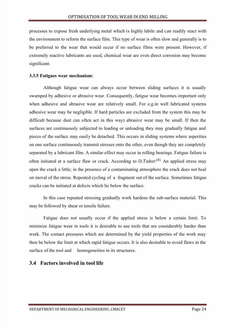
3.3.5 Fatigues wear mechanism:
Although fatigue wear can always occur between sliding surfaces it is usually
swamped by adhesive or abrasive wear. Consequently, fatigue wear becomes important only
when adhesive and abrasive wear are relatively small. For e.g.in well lubricated systems
adhesive wear may be negligible. If hard particles are excluded from the system this may be
difficult because dust can often act in this way) abrasive wear may be small. If then the
surfaces are continuously subjected to loading or unloading they may gradually fatigue and
pieces of the surface may easily be detached. This occurs in sliding systems where asperities
on one surface continuously transmit stresses onto the other, even though they are completely
separated by a lubricant film. A similar effect may occur in rolling bearings. Fatigue failure is
often initiated at a surface flaw or crack. According to D. An applied stress may
open the crack a little; in the presence of a contaminating atmosphere the crack does not heal
on moval of the stress. Repeated cycling of a fragment out of the surface. Sometimes fatigue
cracks can be initiated at defects which lie below the surface.
In this case repeated stressing gradually work hardens the sub-surface material. This
may be followed by shear or tensile failure.
Fatigue does not usually occur if the applied stress is below a certain limit. To
minimize fatigue wear in tools it is desirable to use tools that are considerably harder than
work. The contact pressures which are determined by the yield properties of the work may
then be below the limit at which rapid fatigue occurs. It is also desirable to avoid flaws in the
surface of the tool and homogeneities in its structures.
3.4 Factors involved in tool life
7/15/2019 Optimization of Tool Wear in End Milling
http://slidepdf.com/reader/full/optimization-of-tool-wear-in-end-milling 25/73
OPTIMISATION OF TOOL WEAR IN END MILLING
DEPARTMENT OF MECHANICAL ENGINEERING ,CMRCET Page 25
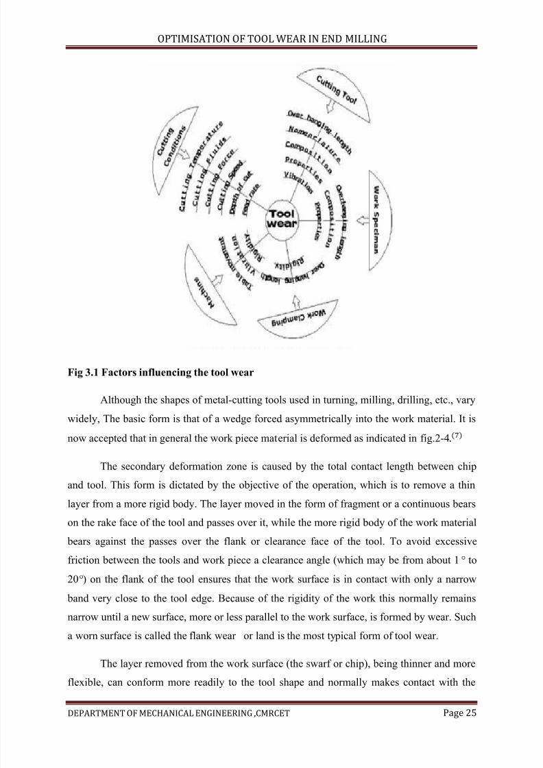
Fig 3.1 Factors influencing the tool wear
Although the shapes of metal-cutting tools used in turning, milling, drilling, etc., varywidely, The basic form is that of a wedge forced asymmetrically into the work material. It is
now accepted that in general the work piece material is deformed as indicated in fig.2-4
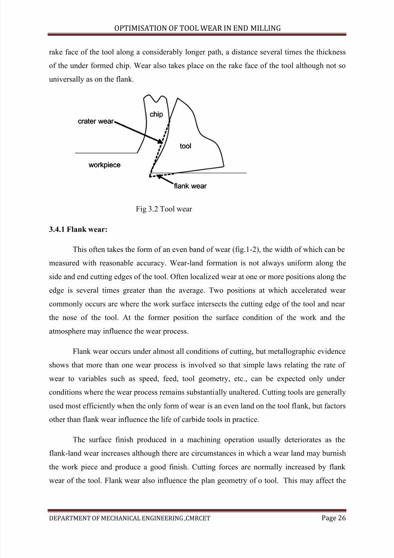
The secondary deformation zone is caused by the total contact length between chip
and tool. This form is dictated by the objective of the operation, which is to remove a thin
layer from a more rigid body. The layer moved in the form of fragment or a continuous bears
on the rake face of the tool and passes over it, while the more rigid body of the work material
bears against the passes over the flank or clearance face of the tool. To avoid excessive
friction between the tools and work piece a clearance angle (which may be from about 1 to
20 ) on the flank of the tool ensures that the work surface is in contact with only a narrow
band very close to the tool edge. Because of the rigidity of the work this normally remains
narrow until a new surface, more or less parallel to the work surface, is formed by wear. Such
a worn surface is called the flank wear or land is the most typical form of tool wear.
The layer removed from the work surface (the swarf or chip), being thinner and more
flexible, can conform more readily to the tool shape and normally makes contact with the
7/15/2019 Optimization of Tool Wear in End Milling
http://slidepdf.com/reader/full/optimization-of-tool-wear-in-end-milling 26/73
OPTIMISATION OF TOOL WEAR IN END MILLING
DEPARTMENT OF MECHANICAL ENGINEERING ,CMRCET Page 26
rake face of the tool along a considerably longer path, a distance several times the thickness
of the under formed chip. Wear also takes place on the rake face of the tool although not so
universally as on the flank.
Fig 3.2 Tool wear
3.4.1 Flank wear:
This often takes the form of an even band of wear (fig.1-2), the width of which can be
measured with reasonable accuracy. Wear-land formation is not always uniform along the
side and end cutting edges of the tool. Often localized wear at one or more positions along the
edge is several times greater than the average. Two positions at which accelerated wear commonly occurs are where the work surface intersects the cutting edge of the tool and near
the nose of the tool. At the former position the surface condition of the work and the
atmosphere may influence the wear process.
Flank wear occurs under almost all conditions of cutting, but metallographic evidence
shows that more than one wear process is involved so that simple laws relating the rate of
wear to variables such as speed, feed, tool geometry, etc., can be expected only under
conditions where the wear process remains substantially unaltered. Cutting tools are generally
used most efficiently when the only form of wear is an even land on the tool flank, but factors
other than flank wear influence the life of carbide tools in practice.
The surface finish produced in a machining operation usually deteriorates as the
flank-land wear increases although there are circumstances in which a wear land may burnish
the work piece and produce a good finish. Cutting forces are normally increased by flank
wear of the tool. Flank wear also influence the plan geometry of o tool. This may affect the
workpiece
tool
crater wear
flank wear
chip
workpiece
tool
crater wear
flank wear
chip
7/15/2019 Optimization of Tool Wear in End Milling
http://slidepdf.com/reader/full/optimization-of-tool-wear-in-end-milling 27/73
OPTIMISATION OF TOOL WEAR IN END MILLING
DEPARTMENT OF MECHANICAL ENGINEERING ,CMRCET Page 27
dimensions of components produced in a machine with set cutting tool positions, or it may
influence the shape of components produced in an operation utilizing a form tool.
Vibration or chatter is another aspect of the cutting process which may be influenced
by tool wear. A wear land increases the tendency of a tool to dynamic instability. A cutting
operation which is quite free of vibration when the tool is sharp may be subjected to an
unacceptable chatter mode when the tool wears.
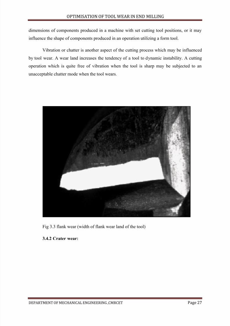
Fig 3.3 flank wear (width of flank wear land of the tool)
3.4.2 Crater wear:
7/15/2019 Optimization of Tool Wear in End Milling
http://slidepdf.com/reader/full/optimization-of-tool-wear-in-end-milling 28/73
OPTIMISATION OF TOOL WEAR IN END MILLING
DEPARTMENT OF MECHANICAL ENGINEERING ,CMRCET Page 28
Fig 3.4 crater wear
On the rake face a cavity or crater frequently forms a short distance from the cuttingedge, as shown in fig.1-2. Once the crater is established, its depth KT grows more rapidly
than its top width KB. The edge of the crater approaches the cutting edge, both by wear of the
crater and by clearance-face wear. This weakens the tool close to the cutting edge and a
major failure may occur by fracture from the crater through to the clearance face. This is
more likely under discontinuous cutting conditions. Cutting forces are normally increased
by wear of the tool. Crater wear may, however, under certain circumstances, reduce forces by
7/15/2019 Optimization of Tool Wear in End Milling
http://slidepdf.com/reader/full/optimization-of-tool-wear-in-end-milling 29/73
OPTIMISATION OF TOOL WEAR IN END MILLING
DEPARTMENT OF MECHANICAL ENGINEERING ,CMRCET Page 29
effectively increasing the rake angle of the tool.
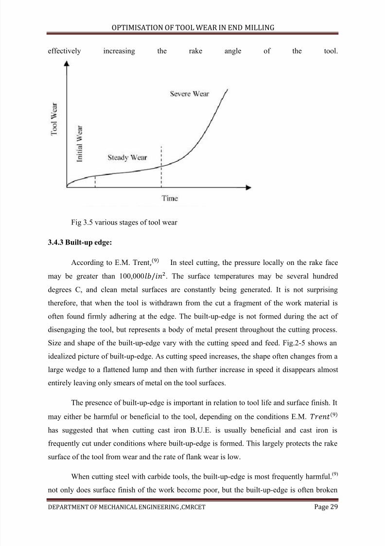
Fig 3.5 various stages of tool wear
3.4.3 Built-up edge:
According to E.M. Trent In steel cutting, the pressure locally on the rake face
may be greater than 100,000. The surface temperatures may be several hundred
degrees C, and clean metal surfaces are constantly being generated. It is not surprising
therefore, that when the tool is withdrawn from the cut a fragment of the work material is
often found firmly adhering at the edge. The built-up-edge is not formed during the act of
disengaging the tool, but represents a body of metal present throughout the cutting process.
Size and shape of the built-up-edge vary with the cutting speed and feed. Fig.2-5 shows an
idealized picture of built-up-edge. As cutting speed increases, the shape often changes from a
large wedge to a flattened lump and then with further increase in speed it disappears almost
entirely leaving only smears of metal on the tool surfaces.
The presence of built-up-edge is important in relation to tool life and surface finish. It
may either be harmful or beneficial to the tool, depending on the conditions E.M.
has suggested that when cutting cast iron B.U.E. is usually beneficial and cast iron is
frequently cut under conditions where built-up-edge is formed. This largely protects the rake
surface of the tool from wear and the rate of flank wear is low.
When cutting steel with carbide tools, the built-up-edge is most frequently harmful.(9)
not only does surface finish of the work become poor, but the built-up-edge is often broken
7/15/2019 Optimization of Tool Wear in End Milling
http://slidepdf.com/reader/full/optimization-of-tool-wear-in-end-milling 30/73
OPTIMISATION OF TOOL WEAR IN END MILLING
DEPARTMENT OF MECHANICAL ENGINEERING ,CMRCET Page 30
away, bringing with its small fragments of the tool edge and leading to rapid breakdown of
the tool. Without dissolving the metal adhering to the tool, the cause of breakdown may not
be obvious and failure may appear to be due to rapid flank wear.
Unlike flank wear, which occurs under almost all conditions of cutting, the built-up-
edge is a factor affecting tool life mainly at low cutting speeds and feeds. To predict tool life,
surface finish, etc., it is important to know and work material concerned.
3.5 Tool deformation:
There is a constant trend in metal cutting to increase metal removal rate by increasing
cutting speed and feed rate. With increased speed the temperature at the edge of the tool is
raised, while both temperature and the stress near the cutting edge are increased with
increments of feed rate. A limit is eventually reached at which the tool material can no longer
resist the combination of stress and temperature, and begins to deform permanently. The
resistance of the tool to deformation may be the property on which depends the upper limit to
the cutting speed and feed which can be used. The development of tool materials from carbon
steel through high-speed steel and cast co-based alloys to cemented carbides represents a
series with increasing resistance to deformation under compressive stress at high temperature.
Deformation is a factor in tool life quite distinct from normal flank wear. Where the
tool tip is not stressed above its elastic limit the wear rate is not related to the resistance to
deformation. As cutting speed and feed are raised, the elastic limit is exceeded and the tool
begins to deform. At first this may have no effect on the wear rate then, rather suddenly, the
limit may be reached of the strain which the tool a withstand, and it may fail suddenly as a
result of local fracture. Such failure may be attributed to flank wear or to mechanical
chipping, unless the tool is carefully examined under the microscope, but it is necessary to
diagnose the failure correctly in order to apply the correct remedy. Tool failure by
mechanical chipping may require the use of a tougher tool material, while to overcome
deformation a harder though less tough tool may be needed. Deformation occurs most
frequently at the nose radius of a tool and may be minimized by attention to tool design. A
tool with a small nose radius will deform at much lower speed and feed then one with a large
radius.
It is useful to know under what conditions deformation of the tool occurs. To
calculate this would require knowledge of the temperature and stress distribution near the
7/15/2019 Optimization of Tool Wear in End Milling
http://slidepdf.com/reader/full/optimization-of-tool-wear-in-end-milling 31/73
OPTIMISATION OF TOOL WEAR IN END MILLING
DEPARTMENT OF MECHANICAL ENGINEERING ,CMRCET Page 31
cutting edge of the tool, knowledge not at present available. Fortunately, much useful
information can be obtained at relatively simple laboratory tests. The flank surface of a tool
tip is lapped optically flat and the tip is then clamped in a tool holder and used for cutting
under controlled conditions. After cutting, any deformation of the tool tip can be observed
and measured by placing the flank surface of the tip on a flat glass plate and examining it
under monochromatic light.
By testing different tool and work material in this way, with varying tool geometry, it
is possible to build-up a body of knowledge concerning conditions under which deformation
of the tool is a factor of importance in tool life, and the relative resistance of a tool material to
deformation
3.5.1 Mechanical chipping:
Chipping of the tool, as the name implies, involves removal of relatively large
discrete particles of tool material. Tools subjected to discontinuous cutting conditions are
particularly prone to chipping. Built – up-edge formation also has a tendency to promote tool
chipping. A built up edge is never completely stable, but it periodically breaks off. Each time
some of the built up material is removed it may take with it a lump of tool edge, to which it
has adhered. This leaves a chipped cutting edge.
Chipping results most frequently from impact of the swarf on part of the cutting edge
not engaged in the cutting, or when starting or stopping the cut, or from careless handling. (9)
it can be greatly reduced by measures taken to control the formation of swarf by chip curlers,
etc ., and by efficient methods of swarf disposal. In many cases honing, or the formation of
small radius or chamfer on the cutting edge of the tool, will prevent this form of damage, or it
may be necessary to use a tougher grade of cemented carbide. In such ways mechanical
chipping can be minimized but its general effect is to cause scatter in the data for tool life,
and often so much scatter as to render work shop test results meaningless.
Again it is important to be able to distinguish correctly between failure due to
mechanical chipping and other causes. To do this with certainty usually requires
microscopical examination of tools treated in acid to remove adhering metal.
3.5.2 Thermal cracking:
7/15/2019 Optimization of Tool Wear in End Milling
http://slidepdf.com/reader/full/optimization-of-tool-wear-in-end-milling 32/73
OPTIMISATION OF TOOL WEAR IN END MILLING
DEPARTMENT OF MECHANICAL ENGINEERING ,CMRCET Page 32
At the cutting edge of the tool very steep temperature gradients exist, and in
interrupted cutting frequent and rapid changes of temperature occur. It is therefore, not
surprising to find, particularly in milling operations, that cracks may be formed across the
cutting edge which can be attributed to the stresses associated with local thermal expansion
and contraction. They may shorten tool life in two ways. If many cracks from close together,
fragments of the tool edge may break away between them. If the tool is subjected to major
stresses in service, the stress concentration at the root of the thermal cracks may result in
failure of the tool by larger scale fracture, but a small number of short thermal cracks does
not appreciably affect the tool life.
There are other factors and causes of wear involved in particular metal cutting
processes but most of these, e.g., oxidation of the tip, or failure due to brazing and grinding
stresses,are avoided by taking reasonable precautions well known to those skilled in the art of
metal cutting or are rarely encountered.
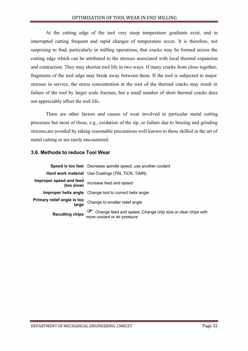
3.6. Methods to reduce Tool Wear
Speed is too fast Decrease spindle speed, use another coolant
Hard work material Use Coatings (TiN, TiCN, TiAlN)
Improper speed and feed
(too slow) Increase feed and speed Improper helix angle Change tool to correct helix angle
Primary relief angle is toolarge
Change to smaller relief angle
Recutting chips Change feed and speed, Change chip size or clear chips withmore coolant or air pressure
7/15/2019 Optimization of Tool Wear in End Milling
http://slidepdf.com/reader/full/optimization-of-tool-wear-in-end-milling 33/73
OPTIMISATION OF TOOL WEAR IN END MILLING
DEPARTMENT OF MECHANICAL ENGINEERING ,CMRCET Page 33
Chapter-4
Introduction to dampers
4.1 Introduction to dampers:
A mechanical damper has been introduced to reduce tool vibration during the high-
speed milling process. The mechanical damper is composed of multi-fingered cylindrical
inserts placed in a matching cylindrical hole in the center of a standard end-milling cutter.
Centrifugal forces during high-speed rotation press the flexible fingers against the inner
surface of the tool. Bending of the tool/damper assembly due to cutting forces or chatter
vibration causes relative axial sliding between the tool inner surface and the damper fingers,
and dissipates energy in the form of friction work.
Damper consists of a multi-fingered cylindrical insert placed inside a matching
axial hole along the center line of the milling cutter. During high speed rotation, centrifugal
forces press the outer surface of the insert fingers against the inner surface of the tool. During
lateral vibrations of the tool, relative sliding occurs at the interface between the damper and
tool inner surface, and the resulting frictional work in the contact interface dissipates energyand reduces vibration amplitude. They developed a simplified analytical model for the multi
fingered cylindrical damper and performed experiments. In this paper, non-linear finite
element analysis with frictional contact is used to study the mechanical damper, and calculate
the amount of friction work during lateral bending of the tool. Although chatter vibration is a
dynamic
Phenomenon, the amount of damping in the proposed system is directly
dependent on the energy dissipated during lateral vibrations. If we assume that the contact
pressure between the damping elements inside the tool is primarily due to centrifugal forces,
i.e. The bending stiffness of the damping elements is small, then static finite element analysis
is sufficient to predict frictional work during static bending.
4.1.1 Use cutters with fewer inserts:
Although it may seem counterintuitive, the first step to reducing chatter in milling
operations is to switch to a cutter with fewer teeth. In general, the coarser the cutter pitch, the
lesser the chance of harmonic vibration. Sometimes, replacing a 16-tooth cutter with a 12-
7/15/2019 Optimization of Tool Wear in End Milling
http://slidepdf.com/reader/full/optimization-of-tool-wear-in-end-milling 34/73
OPTIMISATION OF TOOL WEAR IN END MILLING
DEPARTMENT OF MECHANICAL ENGINEERING ,CMRCET Page 34
tooth tool ends chatter altogether. A differential-pitch cutter may be required in more difficult
cases to eliminate troublesome harmonics.
The larger the cutter, the better the performance will be. Conditions permitting,
larger cutters provide more choices about how to approach the work piece. Varying the
relative position often helps damp vibration. Manufacturing engineers should try to keep the
cutter diameter 20 to 50 percent larger than the width of the cut. The cutter should be sized so
that no more than two-thirds of the inserts are engaged in the cut at any time. These
guidelines help produce an ideal entry angle, thereby reducing cutting forces and vibration.
4.1.2 Optimize insert geometry:
The shape of the cutting inserts often determines their vibration tendency. Round
inserts are most vibration prone, while those with 45-degree lead angles are the least prone to
chatter. The smaller the entry angles of the cutting edge to the work, the lower the tendency
to vibrate.
Cutting tool specifies can reduce overall cutting force and resulting vibration by using
positive rake insert geometry. The shearing action of positive rake cutters reduces cutting
pressure by more than 20 percent versus zero- or negative-rake milling tools. The sharper
edge and angle of entry of this type of insert also helps to reduce the power needed to
penetrate the surface of the work piece.
4.1.3 Choose inserts coatings carefully:
Coatings on inserts perform many functions, but their primary jobs are protecting
against heat, maintaining lubricity and preventing build-up on the insert. To reduce edge
rounding and chatter, you should look to replace inserts protected by thick CVD coatings
with those wearing thinner PVD coatings. Though CVD treatments are formulated for wear
resistance, PVD coatings provide a sharper insert edge and a more positive rake angle to help
minimize vibration.
4.2 End mill cutter damper geometry
The cutting tool (end mill) used in conventional end mills have a solid
cylindrical cross section, the proposed mechanical damper requires an axial hole along the
tool center line . When the multi-fingered cylindrical damper is inserted into the hollow tool,centrifugal forces from the high-speed spindle rotation cause high contact pressures between

7/15/2019 Optimization of Tool Wear in End Milling
http://slidepdf.com/reader/full/optimization-of-tool-wear-in-end-milling 35/73
OPTIMISATION OF TOOL WEAR IN END MILLING
DEPARTMENT OF MECHANICAL ENGINEERING ,CMRCET Page 35
the damper fingers and the inner surface of the tool. When lateral bending of the system
occurs, it causes a Relative sliding motion between the damper and the tool due to their
differences in neutral axis locations. This relative motion in conjunction with the contact
pressure causes a friction stress at the interface, which dissipates the vibration energy. In this
paper, this damping mechanism will be referred to as a mechanical damper. While the
geometry of the cutting edges of the tool is very important for cutting performance, it does
not affect damper performance. Therefore, the tool can be simplified as End mill . Geometry
of end mill and four-fingered mechanical damper.
The simplified ‘damper’ is also modelled as a hollow cylinder, slit along its
length to form individual ‘fingers’. The inner diameter of the tool shank is set to 9.525 mm
and it cannot be made larger because enough material must be left on the shank to allow
cutting teeth to be formed. Thus, although a larger inner diameter of the tool might provide
better damper performance; this is not considered as a design variable since these dimensions
could not be used to produce the actual cutting tool. The damper has an outer diameter of
9.525 mm. The inner diameter of the damper can be changed to maximize the frictional
energy dissipation. The number of fingers can also be altered to improve damping
performance. The parameter study detailed in Section 4 will examine the effect of varying the
number of fingers as well as the damper inner diameter. Because a damper with one finger will not work in the manner described above, this case will not be considered.
.
7/15/2019 Optimization of Tool Wear in End Milling
http://slidepdf.com/reader/full/optimization-of-tool-wear-in-end-milling 36/73
OPTIMISATION OF TOOL WEAR IN END MILLING
DEPARTMENT OF MECHANICAL ENGINEERING ,CMRCET Page 36
CHAPTER-5
EXPERMENTATION
Equipments Used
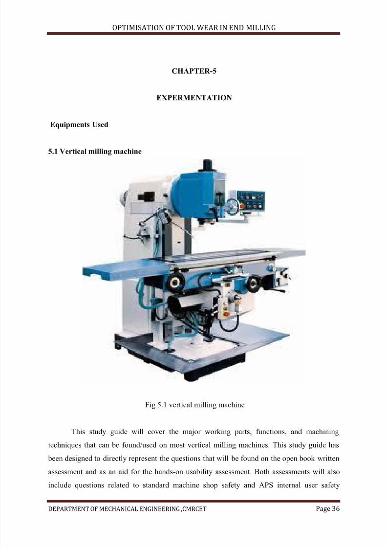
5.1 Vertical milling machine
Fig 5.1 vertical milling machine
This study guide will cover the major working parts, functions, and machining
techniques that can be found/used on most vertical milling machines. This study guide has
been designed to directly represent the questions that will be found on the open book written
assessment and as an aid for the hands-on usability assessment. Both assessments will also
include questions related to standard machine shop safety and APS internal user safety
7/15/2019 Optimization of Tool Wear in End Milling
http://slidepdf.com/reader/full/optimization-of-tool-wear-in-end-milling 37/73
OPTIMISATION OF TOOL WEAR IN END MILLING
DEPARTMENT OF MECHANICAL ENGINEERING ,CMRCET Page 37
guidelines. Answering the questions found at the end of the study guide will enable the user
to successfully pass the hands-on usability and open book written assessments. Study guide
practice test and answers can be found at the end of the guide. The Milling Machine uses a
rotating milling cutter to produce machined surfaces by progressively removing material
from a work piece. The vertical milling machine also can function like a drill press because
the spindle is perpendicular to the table and can be lowered into the work piece.
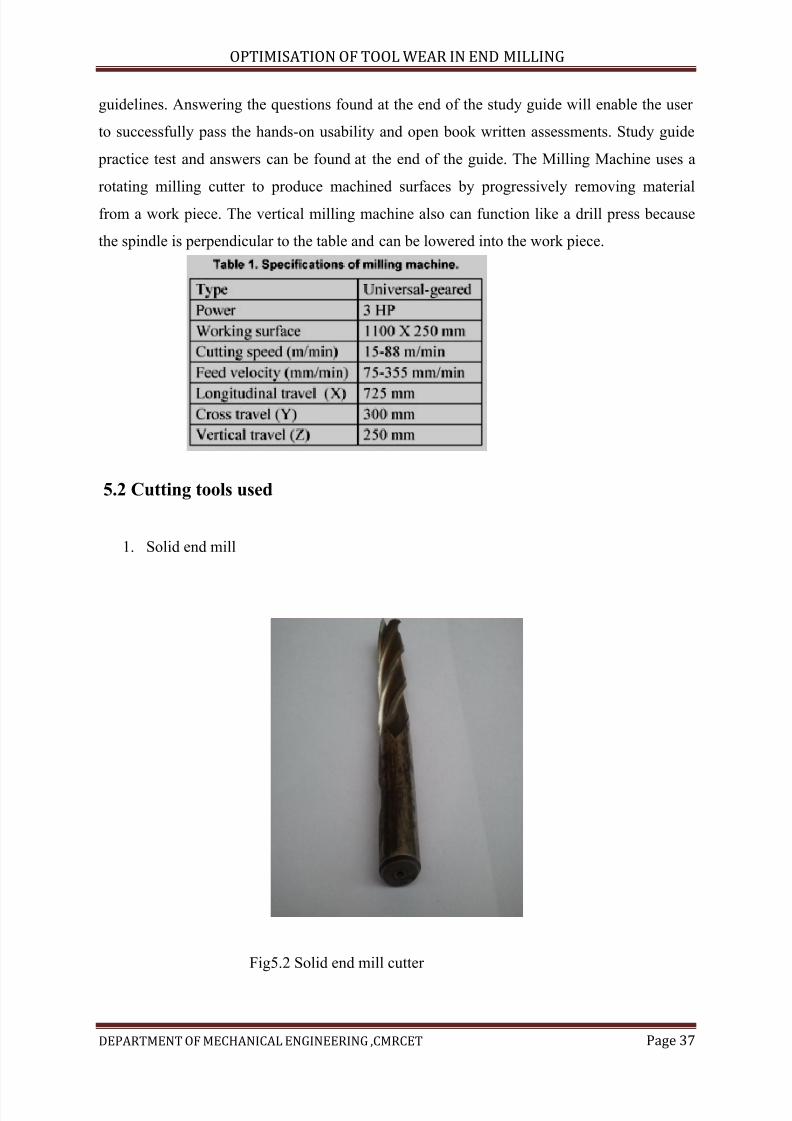
5.2 Cutting tools used
1. Solid end mill
Fig5.2 Solid end mill cutter
7/15/2019 Optimization of Tool Wear in End Milling
http://slidepdf.com/reader/full/optimization-of-tool-wear-in-end-milling 38/73
OPTIMISATION OF TOOL WEAR IN END MILLING
DEPARTMENT OF MECHANICAL ENGINEERING ,CMRCET Page 38
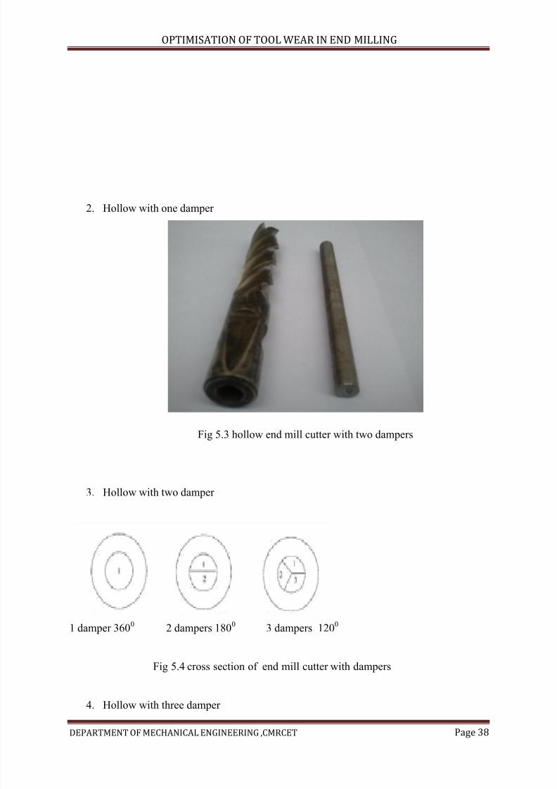
2. Hollow with one damper
Fig 5.3 hollow end mill cutter with two dampers
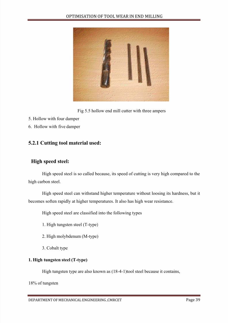
3. Hollow with two damper
1 damper 3600 2 dampers 1800 3 dampers 1200
Fig 5.4 cross section of end mill cutter with dampers
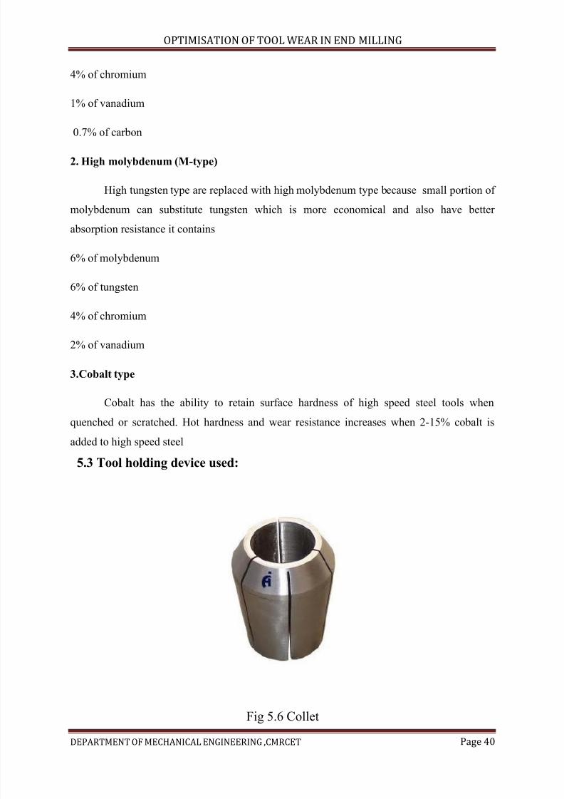
4. Hollow with three damper
7/15/2019 Optimization of Tool Wear in End Milling
http://slidepdf.com/reader/full/optimization-of-tool-wear-in-end-milling 39/73
OPTIMISATION OF TOOL WEAR IN END MILLING
DEPARTMENT OF MECHANICAL ENGINEERING ,CMRCET Page 39
Fig 5.5 hollow end mill cutter with three ampers5. Hollow with four damper
6. Hollow with five damper
5.2.1 Cutting tool material used:
High speed steel:
High speed steel is so called because, its speed of cutting is very high compared to the
high carbon steel.
High speed steel can withstand higher temperature without loosing its hardness, but it
becomes soften rapidly at higher temperatures. It also has high wear resistance.
High speed steel are classified into the following types
1. High tungsten steel (T-type)
2. High molybdenum (M-type)
3. Cobalt type
1. High tungsten steel (T-type)
High tungsten type are also known as (18-4-1)tool steel because it contains,
18% of tungsten
7/15/2019 Optimization of Tool Wear in End Milling
http://slidepdf.com/reader/full/optimization-of-tool-wear-in-end-milling 40/73
OPTIMISATION OF TOOL WEAR IN END MILLING
DEPARTMENT OF MECHANICAL ENGINEERING ,CMRCET Page 40
4% of chromium
1% of vanadium
0.7% of carbon
2. High molybdenum (M-type)
High tungsten type are replaced with high molybdenum type because small portion of
molybdenum can substitute tungsten which is more economical and also have better
absorption resistance it contains
6% of molybdenum
6% of tungsten
4% of chromium
2% of vanadium
3.Cobalt type
Cobalt has the ability to retain surface hardness of high speed steel tools when
quenched or scratched. Hot hardness and wear resistance increases when 2-15% cobalt is
added to high speed steel
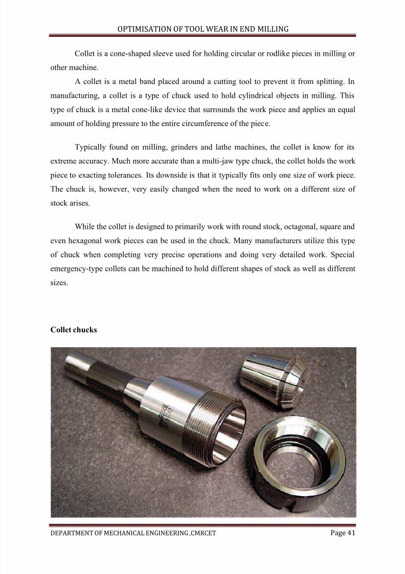
5.3 Tool holding device used:
Fig 5.6 Collet
7/15/2019 Optimization of Tool Wear in End Milling
http://slidepdf.com/reader/full/optimization-of-tool-wear-in-end-milling 41/73
OPTIMISATION OF TOOL WEAR IN END MILLING
DEPARTMENT OF MECHANICAL ENGINEERING ,CMRCET Page 41
Collet is a cone-shaped sleeve used for holding circular or rodlike pieces in milling or
other machine.
A collet is a metal band placed around a cutting tool to prevent it from splitting. In
manufacturing, a collet is a type of chuck used to hold cylindrical objects in milling. This
type of chuck is a metal cone-like device that surrounds the work piece and applies an equal
amount of holding pressure to the entire circumference of the piece.
Typically found on milling, grinders and lathe machines, the collet is know for its
extreme accuracy. Much more accurate than a multi-jaw type chuck, the collet holds the work
piece to exacting tolerances. Its downside is that it typically fits only one size of work piece.
The chuck is, however, very easily changed when the need to work on a different size of
stock arises.
While the collet is designed to primarily work with round stock, octagonal, square and
even hexagonal work pieces can be used in the chuck. Many manufacturers utilize this type
of chuck when completing very precise operations and doing very detailed work. Special
emergency-type collets can be machined to hold different shapes of stock as well as different
sizes.
Collet chucks
7/15/2019 Optimization of Tool Wear in End Milling
http://slidepdf.com/reader/full/optimization-of-tool-wear-in-end-milling 42/73
OPTIMISATION OF TOOL WEAR IN END MILLING
DEPARTMENT OF MECHANICAL ENGINEERING ,CMRCET Page 42
Fig 5.7 Collet chucks
Chucks are made of special hardened steel to withstand many use cycles, as would be
typical in a high-volume manufacturing environment. There are, however, collets made of
brass and even nylon that can be custom made to hold special work pieces. These chucks can
also be made in step models that are machined to hold shorter pieces that have a larger
diameter than the standard size chuck.
There are several advantages to using a collet chuck over a self-centering or multi-jaw
type chuck. To decipher which type of chuck to use there are some key points to consider.
Spindle speed is crucial to chuck choice. A high-speed tooling requires the lower mass chuck
over the higher mass and weight of a self-centering chuck. The lighter weight and less massallows the chuck to accelerate in a much faster manner.
When working on a large run order or creating many identical pieces, the collet
allows for easy stock changing and precise holding. Also, when the parts are of a diameter of
less than three inches, this type of chuck is preferred due to its holding power and easy
operating tendencies. When making multiple operation cuts on a work piece, the collet
provides a much tighter clamping tolerance, thereby ensuring that the outcome of the
different steps will be precise.
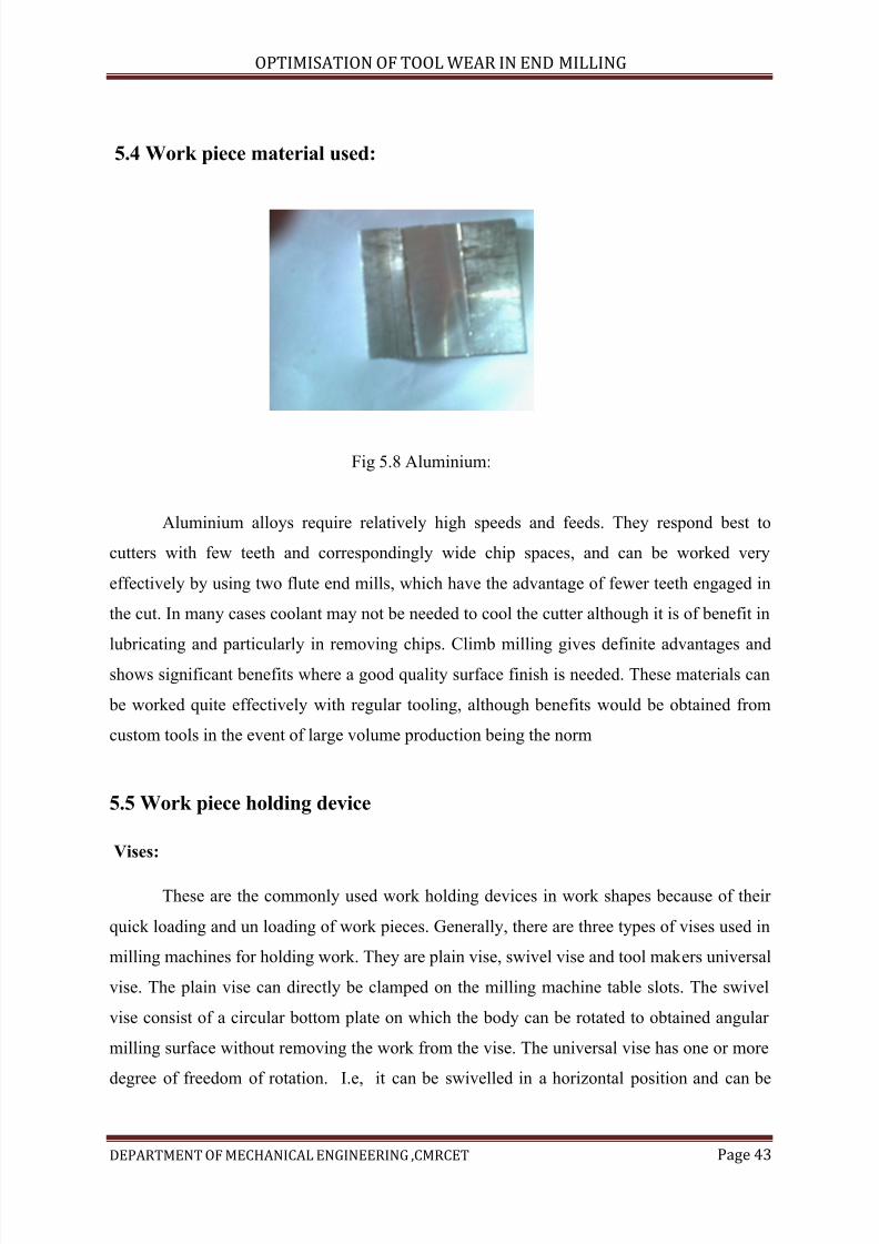
7/15/2019 Optimization of Tool Wear in End Milling
http://slidepdf.com/reader/full/optimization-of-tool-wear-in-end-milling 43/73
OPTIMISATION OF TOOL WEAR IN END MILLING
DEPARTMENT OF MECHANICAL ENGINEERING ,CMRCET Page 43
5.4 Work piece material used:
Fig 5.8 Aluminium:
Aluminium alloys require relatively high speeds and feeds. They respond best to
cutters with few teeth and correspondingly wide chip spaces, and can be worked very
effectively by using two flute end mills, which have the advantage of fewer teeth engaged in
the cut. In many cases coolant may not be needed to cool the cutter although it is of benefit in
lubricating and particularly in removing chips. Climb milling gives definite advantages and
shows significant benefits where a good quality surface finish is needed. These materials can
be worked quite effectively with regular tooling, although benefits would be obtained from
custom tools in the event of large volume production being the norm
5.5 Work piece holding device
Vises:
These are the commonly used work holding devices in work shapes because of their
quick loading and un loading of work pieces. Generally, there are three types of vises used in
milling machines for holding work. They are plain vise, swivel vise and tool makers universal
vise. The plain vise can directly be clamped on the milling machine table slots. The swivel
vise consist of a circular bottom plate on which the body can be rotated to obtained angular
milling surface without removing the work from the vise. The universal vise has one or more
degree of freedom of rotation. I.e, it can be swivelled in a horizontal position and can be
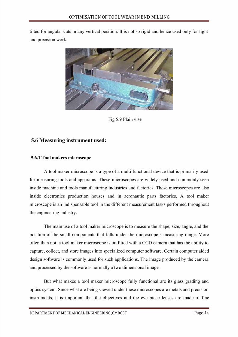
7/15/2019 Optimization of Tool Wear in End Milling
http://slidepdf.com/reader/full/optimization-of-tool-wear-in-end-milling 44/73
OPTIMISATION OF TOOL WEAR IN END MILLING
DEPARTMENT OF MECHANICAL ENGINEERING ,CMRCET Page 44
tilted for angular cuts in any vertical position. It is not so rigid and hence used only for light
and precision work.
Fig 5.9 Plain vise
5.6 Measuring instrument used:
5.6.1 Tool makers microscope
A tool maker microscope is a type of a multi functional device that is primarily used
for measuring tools and apparatus. These microscopes are widely used and commonly seen
inside machine and tools manufacturing industries and factories. These microscopes are also
inside electronics production houses and in aeronautic parts factories. A tool maker
microscope is an indispensable tool in the different measurement tasks performed throughout
the engineering industry.
The main use of a tool maker microscope is to measure the shape, size, angle, and the
position of the small components that falls under the microscope’s measuring range. Moreoften than not, a tool maker microscope is outfitted with a CCD camera that has the ability to
capture, collect, and store images into specialized computer software. Certain computer aided
design software is commonly used for such applications. The image produced by the camera
and processed by the software is normally a two dimensional image.
But what makes a tool maker microscope fully functional are its glass grading and
optics system. Since what are being viewed under these microscopes are metals and precision
instruments, it is important that the objectives and the eye piece lenses are made of fine
7/15/2019 Optimization of Tool Wear in End Milling
http://slidepdf.com/reader/full/optimization-of-tool-wear-in-end-milling 45/73
OPTIMISATION OF TOOL WEAR IN END MILLING
DEPARTMENT OF MECHANICAL ENGINEERING ,CMRCET Page 45
quality glasses only. These essential parts are what makes the device very durable and gives it
the ability to withstand the wear and tear associated with the everyday stress of factory usage.
And much because of this, it is also important that the body, structure, and
mechanisms of a tool maker microscope are created with highly durable materials, most
preferably good quality metals. Because the conditions inside an industrial laboratory are not
as good as a home or office laboratory setup, the microscope’s body should be capable of low
heat production. It should also be able to resist corrosion, oscillation, and pollution – because
all of these elements are present inside an industrial laboratories and production plants.
There are tool maker microscopes that are equipped with a cross hair reticle on the
eye piece, coupled with a protractor on the tube. These are good instruments used toaccurately measure the distance or the diameter of the tool under observation. The
microscope’s stage is also built with a millimeter measuring system that also allows for the
measurement of the specimen. The stage when moved, produce the distance traveled with
which the microscope effectively measures.
Right now, quality tool maker microscopes are using semiconductor laser devices as
directors. Instead of the cross hairs, a red point is virtually marked on the microscope’s
working surface in order to locate the parts that have to be measured by the microscope. The
CCD imaging system can also be used as a measurement system as well. This is another
advanced feature of the newer versions of a tool maker microscope models. A CCD camera
that has the ability to measure diameters and distances is a lot more convenient to use,
especially to beginners.
But aside from all of these, a tool maker microscope should also have a good
illumination system. It is the lights that allows for the superior viewing of tools andspecimens. The higher the luminance value of the light provided by the microscope, the better
its performance is. If necessary, an incandescent lamp should not be used for these
applications. The light that is ideal is the one that produces a nice level of brightness with less
heat. Lamps have life spans too. And because most of a tool maker microscope uses a built-in
lighting system, the light to be used should last for an extended period of time, if and when
possible.
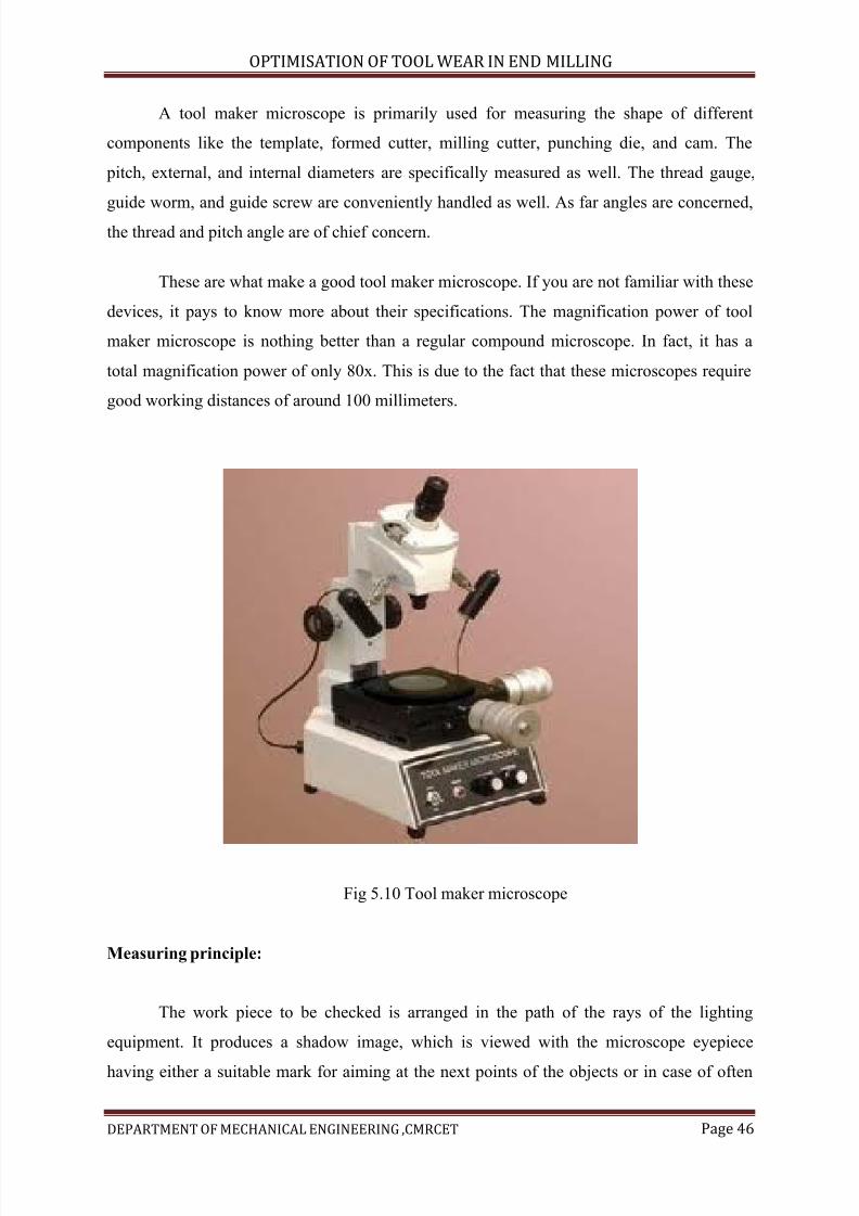
7/15/2019 Optimization of Tool Wear in End Milling
http://slidepdf.com/reader/full/optimization-of-tool-wear-in-end-milling 46/73
OPTIMISATION OF TOOL WEAR IN END MILLING
DEPARTMENT OF MECHANICAL ENGINEERING ,CMRCET Page 46
A tool maker microscope is primarily used for measuring the shape of different
components like the template, formed cutter, milling cutter, punching die, and cam. The
pitch, external, and internal diameters are specifically measured as well. The thread gauge,
guide worm, and guide screw are conveniently handled as well. As far angles are concerned,
the thread and pitch angle are of chief concern.
These are what make a good tool maker microscope. If you are not familiar with these
devices, it pays to know more about their specifications. The magnification power of tool
maker microscope is nothing better than a regular compound microscope. In fact, it has a
total magnification power of only 80x. This is due to the fact that these microscopes require
good working distances of around 100 millimeters.
Fig 5.10 Tool maker microscope
Measuring principle:
The work piece to be checked is arranged in the path of the rays of the lighting
equipment. It produces a shadow image, which is viewed with the microscope eyepiece
having either a suitable mark for aiming at the next points of the objects or in case of often
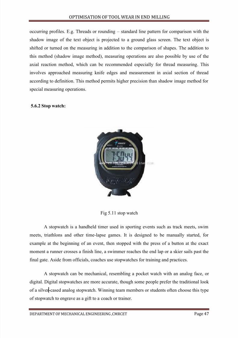
7/15/2019 Optimization of Tool Wear in End Milling
http://slidepdf.com/reader/full/optimization-of-tool-wear-in-end-milling 47/73
OPTIMISATION OF TOOL WEAR IN END MILLING
DEPARTMENT OF MECHANICAL ENGINEERING ,CMRCET Page 47
occurring profiles. E.g. Threads or rounding – standard line pattern for comparison with the
shadow image of the text object is projected to a ground glass screen. The text object is
shifted or turned on the measuring in addition to the comparison of shapes. The addition to
this method (shadow image method), measuring operations are also possible by use of the
axial reaction method, which can be recommended especially for thread measuring. This
involves approached measuring knife edges and measurement in axial section of thread
according to definition. This method permits higher precision than shadow image method for
special measuring operations.
5.6.2 Stop watch:
Fig 5.11 stop watch
A stopwatch is a handheld timer used in sporting events such as track meets, swim
meets, triathlons and other time-lapse games. It is designed to be manually started, for example at the beginning of an event, then stopped with the press of a button at the exact
moment a runner crosses a finish line, a swimmer reaches the end lap or a skier sails past the
final gate. Aside from officials, coaches use stopwatches for training and practices.
A stopwatch can be mechanical, resembling a pocket watch with an analog face, or
digital. Digital stopwatches are more accurate, though some people prefer the traditional look
of a silver-cased analog stopwatch. Winning team members or students often choose this type
of stopwatch to engrave as a gift to a coach or trainer.

7/15/2019 Optimization of Tool Wear in End Milling
http://slidepdf.com/reader/full/optimization-of-tool-wear-in-end-milling 48/73
OPTIMISATION OF TOOL WEAR IN END MILLING
DEPARTMENT OF MECHANICAL ENGINEERING ,CMRCET Page 48
A stopwatch can have many functions or modes, depending on the model. Even a
basic stopwatch will keep a running time and "split" or lap time, which allows the user to
keep track of individual laps or events and cumulative time. Some models only store up to 10
lap times, while other models will be able to store 50 laps or more. If the distance of a track
or lane is known, some stopwatches will also calculate speed based on the time it takes for
the competitor to cover the distance.
7/15/2019 Optimization of Tool Wear in End Milling
http://slidepdf.com/reader/full/optimization-of-tool-wear-in-end-milling 49/73
OPTIMISATION OF TOOL WEAR IN END MILLING
DEPARTMENT OF MECHANICAL ENGINEERING ,CMRCET Page 49
Chapter-6
Introduction to ANOVA analysis and Taguchi design
6.1 Definition of 'Analysis Of Variance - ANOVA'
A statistical analysis tool that separates the total variability found within a data set
into two components: random and systematic factors. The random factors do not have any
statistical influence on the given data set, while the systematic factors do. The ANOVA test is
used to determine the impact independent variables have on the dependent variable in a
sregression analysis.
6.2 Analysis of variance (ANOVA):Purpose:
The reason for doing an ANOVA is to see if there is any difference between groups
on some variable. For example, you might have data on student performance in non-assessed
tutorial exercises as well as their final grading. You are interested in seeing if tutorial
performance is related to final grade. Anova allows you to break up the group according to
the grade and then see if performance is different across these grades. Anova is available for
both parametric (score data) and non-parametric (ranking/ordering) data.
6.3 Types of anova:
One-way between groups:
The example given above is called a one-way between groups model. You are looking
at the differences between the groups. There is only one grouping (final grade) which you areusing to define the groups. This is the simplest version of anova. This type of anova can also
be used to compare variables between different groups - tutorial performance from different
intakes.
One-way repeated measures:
A one way repeated measures anova is used when you have a single group on which
you have measured something a few times. For example, you may have a test of
7/15/2019 Optimization of Tool Wear in End Milling
http://slidepdf.com/reader/full/optimization-of-tool-wear-in-end-milling 50/73
OPTIMISATION OF TOOL WEAR IN END MILLING
DEPARTMENT OF MECHANICAL ENGINEERING ,CMRCET Page 50
understanding of classes. You give this test at the beginning of the topic, at the end of the
topic and then at the end of the subject. You would use a one-way repeated measures anova
to see if student performance on the test changed over time.
Two-way between groups:
A two-way between groups anova is used to look at complex groupings. For example,
the grades by tutorial analysis could be extended to see if overseas students performed
differently to local students what you would have from this form of anova is: the effect of
final grade the effect of overseas versus local the interaction between final grade and
overseas/local each of the main effects are one-way tests the interaction effect is simply
asking "is there any significant difference in performance when you take. Final grade andoverseas/local acting together"
Two-way repeated measures:
This version of anova simple uses the repeated measures structure includes an
interaction effect. In the example given for one-way between groups, you could add gender
and see if there was any joint effect of gender and time of testing - i.e. Do males and females
differ in the amount they remember absorb over time. Nonparametric and parametric anova is
available for score or interval data as parametric anova. This is the type of anova you do from
the standard menu options in a statistical package. The non-parametric version is usually
found under the heading "nonparametric test". It is used when you have rank or ordered data.
You cannot use parametric anova when you data is below interval measurement. Where you
have categorical data you do not have an anova method – you would have to use chi-square
which is about
6.4 Taguchi designs
Quality was the watchword of 1980s, and Genichi Taguchi was a leader in the
growth of quality consciousness. One of Taguchi’s technical contributions to the field of
quality control was a new approach to industrial experimentation. The purpose of the Taguchi
method was to develop products that worked well in spite of natural variation in materials,
operators, suppliers, and environmental change. This is robust engineering.
7/15/2019 Optimization of Tool Wear in End Milling
http://slidepdf.com/reader/full/optimization-of-tool-wear-in-end-milling 51/73
OPTIMISATION OF TOOL WEAR IN END MILLING
DEPARTMENT OF MECHANICAL ENGINEERING ,CMRCET Page 51
Much of the Taguchi method is traditional. His orthogonal arrays are two-level, three-
level, and mixed-level fractional factorial designs. The unique aspects of his approach are the
use of signal and noise factors, inner and outer arrays, and signal-to-noise ratios.
The goal of the Taguchi method is to find control factor settings that generate
acceptable responses despite natural environmental and process variability. In each
experiment, Taguchi’s design approach employs two designs called the inner and outer array.
The Taguchi experiment is the cross product of these two arrays. The control factors, used to
tweak the process, form the inner array. The noise factors, associated with process or
environmental variability, form the outer array. Taguchi’s signal-to-noise ratios are functions
of the observed responses over an outer array. The Taguchi designer supports all these
features of the Taguchi method. You choose from inner and outer array designs, which use
the traditional Taguchi orthogonal arrays, such as L4, L8, and L16.
Dividing system variables according to their signal and noise factors is a key
ingredient in robust engineering. Signal factors are system control inputs. Noise factors are
variables that are typically difficult or expensive to control.
The inner array is a design in the signal factors and the outer array is a design in the
noise factors. A signal-to-noise ratio is a statistic calculated over an entire outer array. Its
formula depends on whether the experimental goal is to maximize, minimize or match a
target value of the quality characteristic of interest.
A Taguchi experiment repeats the outer array design for each run of the inner array.
The response variable in the data analysis is not the raw response or quality characteristic; it
is the signal-to-noise ratio.
The Taguchi designer in JMP supports signal and noise factors, inner and outer
arrays, and signal-to-noise ratios as Taguchi specifies.
6.5 Introduction to Taguchi method
Every experimenter has to plan and conduct experiments to obtain enough and
relevant data so that he can infer the science behind the observed phenomenon. He can do so
by,
1.Trial and error method:
7/15/2019 Optimization of Tool Wear in End Milling
http://slidepdf.com/reader/full/optimization-of-tool-wear-in-end-milling 52/73
OPTIMISATION OF TOOL WEAR IN END MILLING
DEPARTMENT OF MECHANICAL ENGINEERING ,CMRCET Page 52
Performing a series of experiments each of which gives some understanding. This
requires making measurements after every experiment so that analysis of observed data will
allow him to decide what to do next - "which parameters should be varied and by how much".
Many a times such series does not progress much as negative results may discourage or will
not allow a selection of parameters which ought to be changed in the next experiment.
Therefore, such experimentation usually ends well before the number of experiment reach a
double digit! The data is insufficient to draw any significant conclusions and the main
problem (of understanding the science) still remains unsolved.
2. Design of experiments:
A well planned set of experiments, in which all parameters of interest are varied over
a specified range, is a much better approach to obtain systematic data. Mathematically
speaking, such a complete set of experiments ought to give desired results. Usually the
number of experiments and resources (materials and time) required are prohibitively large.
Often the experimenter decides to perform a subset of the complete set of experiments to save
on time and money! However, it does not easily lend itself to understanding of science behind
the phenomenon. The analysis is not very easy (though it may be easy for themathematician/statistician) and thus effects of various parameters on the observed data are
not readily apparent. In many cases, particularly those in which some optimization is
required, the method does not point to the best settings of parameters. A classic example
illustrating the drawback of design of experiments is found in the planning of a world cup
event, say football. While all matches are well arranged with respect to the different teams
and different venues on differ rent dates and yet the planning does not care about the result of
any match (win or lose)!!!! Obviously, such a strategy is not desirable for conducting
scientific experiments
6.6 Taguchi method
Dr. Taguchi of Nippon telephones and telegraph company, Japan has developed a
method based on “orthogonal array" experiments which gives much reduced " variance " for
the experiment with " optimum settings " of control parameters. Thus the marriage of design
of experiments with optimization of control parameters to obtain best results is achieved in
the Taguchi method. "orthogonal arrays" (oa) provide a set of well balanced (minimum)
7/15/2019 Optimization of Tool Wear in End Milling
http://slidepdf.com/reader/full/optimization-of-tool-wear-in-end-milling 53/73
OPTIMISATION OF TOOL WEAR IN END MILLING
DEPARTMENT OF MECHANICAL ENGINEERING ,CMRCET Page 53
experiments and Dr. Taguchi signal-to-noise ratios (s/n), which are log functions of desired
output, serve as objective functions for optimization, help in data analysis and prediction of
optimum results.
6.7 Taguchi method treats optimization problems in two categories,
6.7.1 Static problems:
Generally, a process to be optimized has several control factors which directly decide the
target or desired value of the output. The optimization then involves determining the best control
factor levels so that the output is at the target value. Such a problem is called as a "static problem".
This is best explained using a p-diagram ("p" stands for process or product). Noise is
shown to be present in the process but should have no effect on the output! This is the
primary aim of the Taguchi experiments - to minimize variations in output even though noise
is present in the process. The process is then said to have become robust.
6.7.2 Dynamic problems:
If the product to be optimized has a signal input that directly decides the output, the
optimization involves determining the best control factor levels so that the "input signal / output" ratio
is closest to the desired relationship. Such a problem is called as a "Dynamic problem".
This is best explained by a p-diagram which is shown below. Again, the primary aim of the
Taguchi experiments - to minimize variations in output even though noise is present in the process- is
achieved by getting improved linearity in the input/output relationship.
6.8 Types of static problem s/n ratio’s: (batch process optimization)
There are 3 signal-to-noise ratios of common interest for optimization of static problems;
(a). Smaller-the-better:
N = -10 log10 [mean of sum of squares of measured data]
7/15/2019 Optimization of Tool Wear in End Milling
http://slidepdf.com/reader/full/optimization-of-tool-wear-in-end-milling 54/73
OPTIMISATION OF TOOL WEAR IN END MILLING
DEPARTMENT OF MECHANICAL ENGINEERING ,CMRCET Page 54
This is usually the chosen s/n ratio for all undesirable characteristics like "defects"
etc. For which the ideal value is zero. Also, when an ideal value is finite and its maximum or
minimum value is defined (like maximum purity is 100% or maximum tc is 92k or minimum
time for making a telephone connection is 1 sec) then the difference between measured data
and ideal value is expected to be as small as possible. The generic form of s/n ratio then
becomes,
N = -10 log10 [mean of sum of squares of {measured - ideal}]
(b). Larger-the-better:
N = -10 log10 [mean of sum squares of reciprocal of measured data]
This case has been converted to smaller-the-better by taking the reciprocals of
measured data and then taking the s/n ratio as in the smaller-the-better case.
(c). Nominal-the-best:
Square of mean
n = 10 log10 -----------------
variance
This case arises when a specified value is most desired, meaning that neither a smaller
nor a larger value is desirable.
Examples are;
(i) Most parts in mechanical fittings have dimensions which are nominal-the-best type.
(ii) Ratios of chemicals or mixtures are nominally the best type.
E.g. Aqua regia 1:3 of hno3:hcl
ratio of sulphur, kno3 and carbon in gun powder
7/15/2019 Optimization of Tool Wear in End Milling
http://slidepdf.com/reader/full/optimization-of-tool-wear-in-end-milling 55/73
OPTIMISATION OF TOOL WEAR IN END MILLING
DEPARTMENT OF MECHANICAL ENGINEERING ,CMRCET Page 55
(iii) Thickness should be uniform in deposition /growth /plating /etching..
6.9 Types of dynamic problem s/n ratio’s (technology development) :
In dynamic problems, we come across many applications where the output is supposed to
follow input signal in a predetermined manner. Generally, a linear relationship between "input"
"output" is desirable.
For example: accelerator peddle in cars,
volume control in audio amplifiers,
document copier (with magnification or reduction)
various types of moldings
etc.
There are 2 characteristics of common interest in "follow-the-leader" or
"transformations" type of applications,
(i) Slope of the i/o characteristics
And
(ii)Linearity of the i/o characteristics
(minimum deviation from the best-fit straight line)
The signal-to-noise ratio for these 2 characteristics have been defined as;
(a).Sensitivity (slope):
The slope of i/o characteristics should be at the specified value (usually 1).
It is often treated as larger-the-better when the output is a desirable characteristics (as
in the case of sensors, where the slope indicates the sensitivity).
N = 10 log10 [square of slope or beta of the i/o characteristics]
On the other hand, when the output is an undesired characteristics it can be treated as
smaller-the-better.
N = -10 log10 [square of slope or beta of the i/o characteristics]
7/15/2019 Optimization of Tool Wear in End Milling
http://slidepdf.com/reader/full/optimization-of-tool-wear-in-end-milling 56/73
OPTIMISATION OF TOOL WEAR IN END MILLING
DEPARTMENT OF MECHANICAL ENGINEERING ,CMRCET Page 56
(b). Linearity (larger-the-better)
Most dynamic characteristics are required to have direct proportionality between the
input and output. These applications are therefore called as "transformations". The straight
line relationship between i/o must be truly linear i.e. With as little deviations from the straight
line as possible.
Square of slope or beta
n = 10 log10 ----------------------------
variance
Variance in this case is the mean of the sum of squares of deviations of measured data
points from the best-fit straight line (linear regression).
6.10 8-Steps in Taguchi methodology:
Taguchi method is a scientifically disciplined mechanism for evaluating and implementing
improvements in products, processes, materials, equipment, and facilities. These
improvements are aimed at improving the desired characteristics and simultaneously reducing
the number of defects by studying the key variables controlling the process and optimizing
the procedures or design to yield the best results.
The method is applicable over a wide range of engineering fields that include
processes that manufacture raw materials, sub systems, products for professional and
consumer markets. In fact, the method can be applied to any process be it engineering
fabrication, computer-aided-design, banking and service sectors etc. Taguchi method is
useful for 'tuning' a given process for 'best' results.
Taguchi proposed a standard 8-step procedure for applying his method for optimizing
any process
Step-1: identify the main function, side effects, and failure mode
Step-2: identify the noise factors, testing conditions, and quality characteristics
Step-3: identify the objective function to be optimized
Step-4: identify the control factors and their levels
7/15/2019 Optimization of Tool Wear in End Milling
http://slidepdf.com/reader/full/optimization-of-tool-wear-in-end-milling 57/73
OPTIMISATION OF TOOL WEAR IN END MILLING
DEPARTMENT OF MECHANICAL ENGINEERING ,CMRCET Page 57
Step-5: select the orthogonal array matrix experiment
Step-6: conduct the matrix experiment
Step-7: analyze the data predict the optimum levels and performance
Step-8: perform the verification experiment an plan the future action
A technique for designing and performing experiments to investigate processes where
the output depends on many factors (variables; inputs) without having to tediously and
uneconomically run the process using all possible combinations of values of those variables.
By systematically choosing certain combinations of variables it is possible to separate their
individual effects.
A special variant of design of experiments (doe) that distinguishes itself from classic
doe in the focus on optimizing design parameters to minimize variation before optimizing
design to hit mean target values for output parameters.
6.11 Signal to Noise (S/N) Ratios:
The product/process/system design phase involves deciding the best values/levels for the control factors. The signal to noise (S/N) ratio is an ideal metric for that purpose.
The equation for average quality loss, Q, says that the customer’s average quality loss
depends on the deviation of the mean from the target and also on the variance. An important
class of design optimization problem requires minimization of the variance while keeping the
mean on target.
Between the mean and standard deviation, it is typically easy to adjust the mean on
target, but reducing the variance is difficult. Therefore, the designer should minimize the
variance first and then adjust the mean on target.Among the available control factors most of
them should be used to reduce variance. Only one or two control factors are adequate for
adjusting the mean on target.
The design optimization problem can be solved in two steps:
1. Maximize the S/N ratio, h, defined as
H = 10 log10 ( h2~ / sigma2 )
7/15/2019 Optimization of Tool Wear in End Milling
http://slidepdf.com/reader/full/optimization-of-tool-wear-in-end-milling 58/73
OPTIMISATION OF TOOL WEAR IN END MILLING
DEPARTMENT OF MECHANICAL ENGINEERING ,CMRCET Page 58
This is the step of variance reduction.
2. Adjust the mean on target using a control factor that has no effect on h. Such a factor is
called a scaling factor. This is the step of adjusting the mean on target.
One typically looks for one scaling factor to adjust the mean on target during design
and another for adjusting the mean to compensate for process variation during manufacturing
6.12 Static versus Dynamic S/N Ratios:
In some engineering problems, the signal factor is absent or it takes a fixed value.
These problems are called Static problems and the corresponding S/N ratios are called static
S/N ratios. The S/N ratio described in the preceding section is a static S/N ratio.
In other problems, the signal and response must follow a function called the ideal
function. In the cooling system example described earlier, the response (room temperature)
and signal (set point) must follow a linear relationship. Such problems are called dynamic
problems and the corresponding S/N ratios are called dynamic S/N ratios.
The dynamic S/N ratio will be illustrated in a later section using a turbine design
example.
Dynamic S/N ratios are very useful for technology development, which is the process
of generating flexible solutions that can be used in many products.
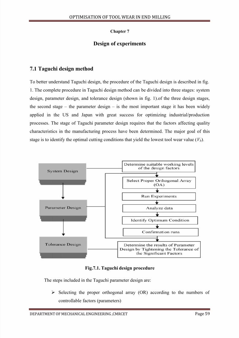
7/15/2019 Optimization of Tool Wear in End Milling
http://slidepdf.com/reader/full/optimization-of-tool-wear-in-end-milling 59/73
OPTIMISATION OF TOOL WEAR IN END MILLING
DEPARTMENT OF MECHANICAL ENGINEERING ,CMRCET Page 59
Chapter 7
Design of experiments
7.1 Taguchi design method
To better understand Taguchi design, the procedure of the Taguchi design is described in fig.
1. The complete procedure in Taguchi design method can be divided into three stages: system
design, parameter design, and tolerance design (shown in fig. 1).of the three design stages,
the second stage – the parameter design – is the most important stage it has been widely
applied in the US and Japan with great success for optimizing industrial/production
processes. The stage of Taguchi parameter design requires that the factors affecting quality
characteristics in the manufacturing process have been determined. The major goal of this
stage is to identify the optimal cutting conditions that yield the lowest tool wear value (V b).
Fig.7.1. Taguchi design procedure
The steps included in the Taguchi parameter design are:
Selecting the proper orthogonal array (OR) according to the numbers of
controllable factors (parameters)
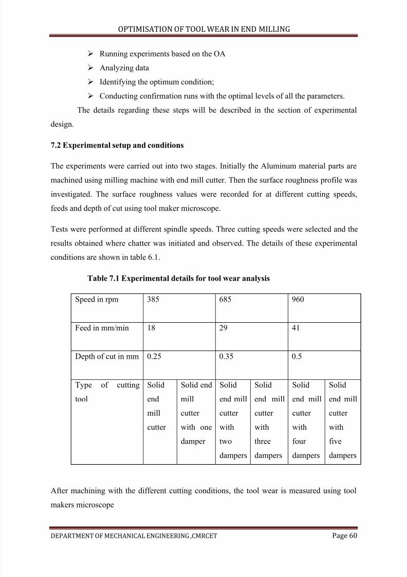
7/15/2019 Optimization of Tool Wear in End Milling
http://slidepdf.com/reader/full/optimization-of-tool-wear-in-end-milling 60/73
OPTIMISATION OF TOOL WEAR IN END MILLING
DEPARTMENT OF MECHANICAL ENGINEERING ,CMRCET Page 60
Running experiments based on the OA
Analyzing data
Identifying the optimum condition;
Conducting confirmation runs with the optimal levels of all the parameters.
The details regarding these steps will be described in the section of experimental
design.
7.2 Experimental setup and conditions
The experiments were carried out into two stages. Initially the Aluminum material parts are
machined using milling machine with end mill cutter. Then the surface roughness profile was
investigated. The surface roughness values were recorded for at different cutting speeds,
feeds and depth of cut using tool maker microscope.
Tests were performed at different spindle speeds. Three cutting speeds were selected and the
results obtained where chatter was initiated and observed. The details of these experimental
conditions are shown in table 6.1.
Table 7.1 Experimental details for tool wear analysis
Speed in rpm 385 685 960
Feed in mm/min 18 29 41
Depth of cut in mm 0.25 0.35 0.5
Type of cutting
tool
Solid
end
mill
cutter
Solid end
mill
cutter
with one
damper
Solid
end mill
cutter
with
two
dampers
Solid
end mill
cutter
with
three
dampers
Solid
end mill
cutter
with
four
dampers
Solid
end mill
cutter
with
five
dampers
After machining with the different cutting conditions, the tool wear is measured using tool
makers microscope
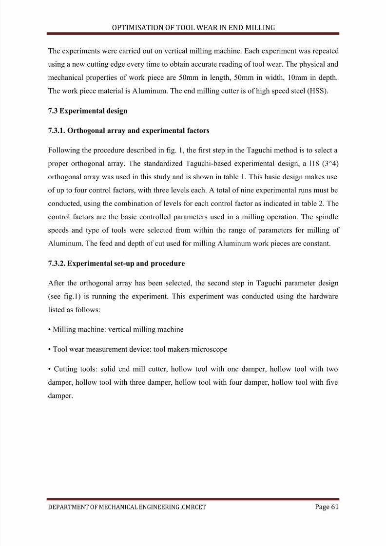
7/15/2019 Optimization of Tool Wear in End Milling
http://slidepdf.com/reader/full/optimization-of-tool-wear-in-end-milling 61/73
OPTIMISATION OF TOOL WEAR IN END MILLING
DEPARTMENT OF MECHANICAL ENGINEERING ,CMRCET Page 61
The experiments were carried out on vertical milling machine. Each experiment was repeated
using a new cutting edge every time to obtain accurate reading of tool wear. The physical and
mechanical properties of work piece are 50mm in length, 50mm in width, 10mm in depth.
The work piece material is Aluminum. The end milling cutter is of high speed steel (HSS).
7.3 Experimental design
7.3.1. Orthogonal array and experimental factors
Following the procedure described in fig. 1, the first step in the Taguchi method is to select a
proper orthogonal array. The standardized Taguchi-based experimental design, a l18 (3^4)
orthogonal array was used in this study and is shown in table 1. This basic design makes use
of up to four control factors, with three levels each. A total of nine experimental runs must be
conducted, using the combination of levels for each control factor as indicated in table 2. The
control factors are the basic controlled parameters used in a milling operation. The spindle
speeds and type of tools were selected from within the range of parameters for milling of
Aluminum. The feed and depth of cut used for milling Aluminum work pieces are constant.
7.3.2. Experimental set-up and procedure
After the orthogonal array has been selected, the second step in Taguchi parameter design(see fig.1) is running the experiment. This experiment was conducted using the hardware
listed as follows:
• Milling machine: vertical milling machine
• Tool wear measurement device: tool makers microscope
• Cutting tools: solid end mill cutter, hollow tool with one damper, hollow tool with two
damper, hollow tool with three damper, hollow tool with four damper, hollow tool with five
damper.
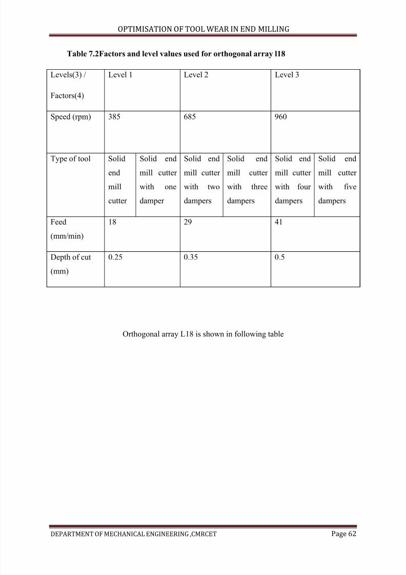
7/15/2019 Optimization of Tool Wear in End Milling
http://slidepdf.com/reader/full/optimization-of-tool-wear-in-end-milling 62/73
OPTIMISATION OF TOOL WEAR IN END MILLING
DEPARTMENT OF MECHANICAL ENGINEERING ,CMRCET Page 62
Table 7.2Factors and level values used for orthogonal array l18
Levels(3) /
Factors(4)
Level 1 Level 2 Level 3
Speed (rpm) 385 685 960
Type of tool Solid
end
mill
cutter
Solid end
mill cutter
with one
damper
Solid end
mill cutter
with two
dampers
Solid end
mill cutter
with three
dampers
Solid end
mill cutter
with four
dampers
Solid end
mill cutter
with five
dampers
Feed
(mm/min)
18 29 41
Depth of cut
(mm)
0.25 0.35 0.5
Orthogonal array L18 is shown in following table
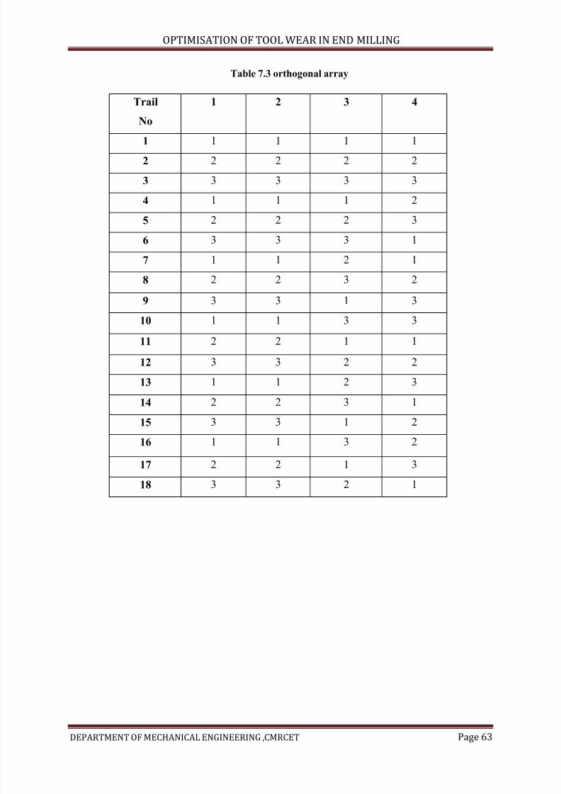
7/15/2019 Optimization of Tool Wear in End Milling
http://slidepdf.com/reader/full/optimization-of-tool-wear-in-end-milling 63/73
OPTIMISATION OF TOOL WEAR IN END MILLING
DEPARTMENT OF MECHANICAL ENGINEERING ,CMRCET Page 63
Table 7.3 orthogonal array
Trail
No
1 2 3 4
1 1 1 1 1
2 2 2 2 2
3 3 3 3 3
4 1 1 1 2
5 2 2 2 3
6 3 3 3 1
7 1 1 2 1
8 2 2 3 2
9 3 3 1 3
10 1 1 3 3
11 2 2 1 1
12 3 3 2 2
13 1 1 2 3
14 2 2 3 1
15 3 3 1 2
16 1 1 3 2
17 2 2 1 3
18 3 3 2 1
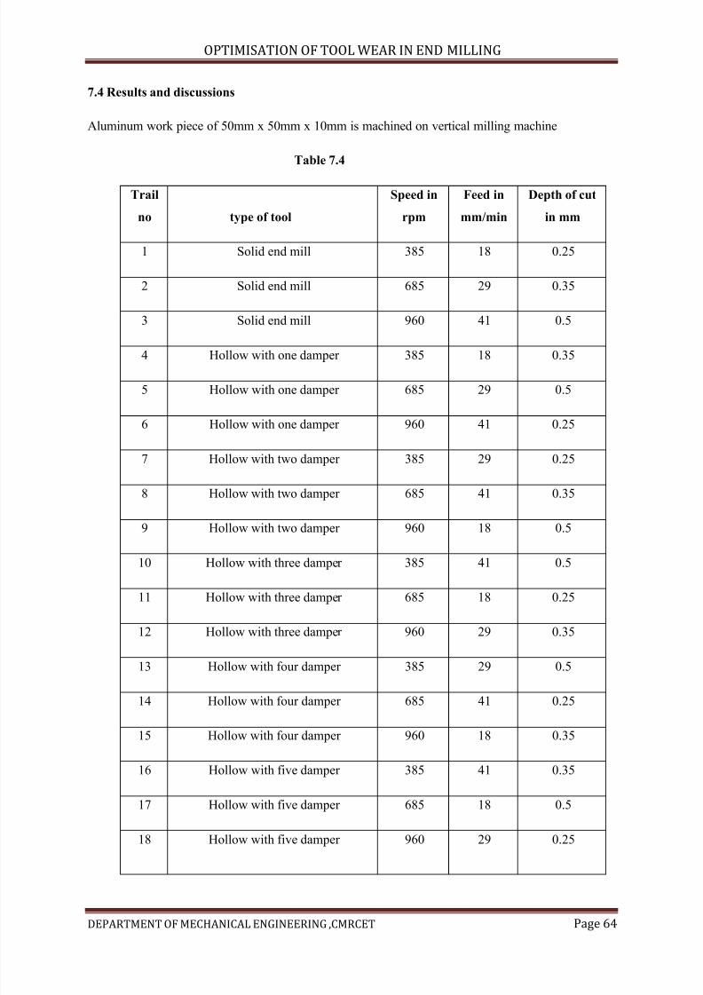
7/15/2019 Optimization of Tool Wear in End Milling
http://slidepdf.com/reader/full/optimization-of-tool-wear-in-end-milling 64/73
OPTIMISATION OF TOOL WEAR IN END MILLING
DEPARTMENT OF MECHANICAL ENGINEERING ,CMRCET Page 64
7.4 Results and discussions
Aluminum work piece of 50mm x 50mm x 10mm is machined on vertical milling machine
Table 7.4
Trail
no type of tool
Speed in
rpm
Feed in
mm/min
Depth of cut
in mm
1 Solid end mill 385 18 0.25
2 Solid end mill 685 29 0.35
3 Solid end mill 960 41 0.5
4 Hollow with one damper 385 18 0.35
5 Hollow with one damper 685 29 0.5
6 Hollow with one damper 960 41 0.25
7 Hollow with two damper 385 29 0.25
8 Hollow with two damper 685 41 0.35
9 Hollow with two damper 960 18 0.5
10 Hollow with three damper 385 41 0.5
11 Hollow with three damper 685 18 0.25
12 Hollow with three damper 960 29 0.35
13 Hollow with four damper 385 29 0.5
14 Hollow with four damper 685 41 0.25
15 Hollow with four damper 960 18 0.35
16 Hollow with five damper 385 41 0.35
17 Hollow with five damper 685 18 0.5
18 Hollow with five damper 960 29 0.25
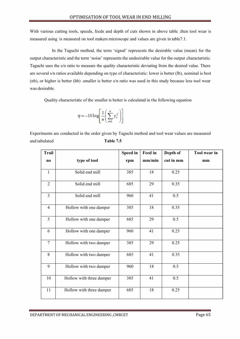
7/15/2019 Optimization of Tool Wear in End Milling
http://slidepdf.com/reader/full/optimization-of-tool-wear-in-end-milling 65/73
OPTIMISATION OF TOOL WEAR IN END MILLING
DEPARTMENT OF MECHANICAL ENGINEERING ,CMRCET Page 65
With various cutting tools, speeds, feeds and depth of cuts shown in above table .then tool wear is
measured using is measured on tool makers microscope and values are given in table7.1.
In the Taguchi method, the term ‘signal’ represents the desirable value (mean) for the
output characteristic and the term ‘noise’ represents the undesirable value for the output characteristic.Taguchi uses the s/n ratio to measure the quality characteristic deviating from the desired value. There
are several s/n ratios available depending on type of characteristic: lower is better (lb), nominal is best
(nb), or higher is better (hb) .smaller is better s/n ratio was used in this study because less tool wear
was desirable.
Quality characteristic of the smaller is better is calculated in the following equation
Experiments are conducted in the order given by Taguchi method and tool wear values are measured
and tabulated Table 7.5
Trail
no type of tool
Speed in
rpm
Feed in
mm/min
Depth of
cut in mm
Tool wear in
mm
1 Solid end mill 385 18 0.25
2 Solid end mill 685 29 0.35
3 Solid end mill 960 41 0.5
4 Hollow with one damper 385 18 0.35
5 Hollow with one damper 685 29 0.5
6 Hollow with one damper 960 41 0.25
7 Hollow with two damper 385 29 0.25
8 Hollow with two damper 685 41 0.35
9 Hollow with two damper 960 18 0.5
10 Hollow with three damper 385 41 0.5
11 Hollow with three damper 685 18 0.25
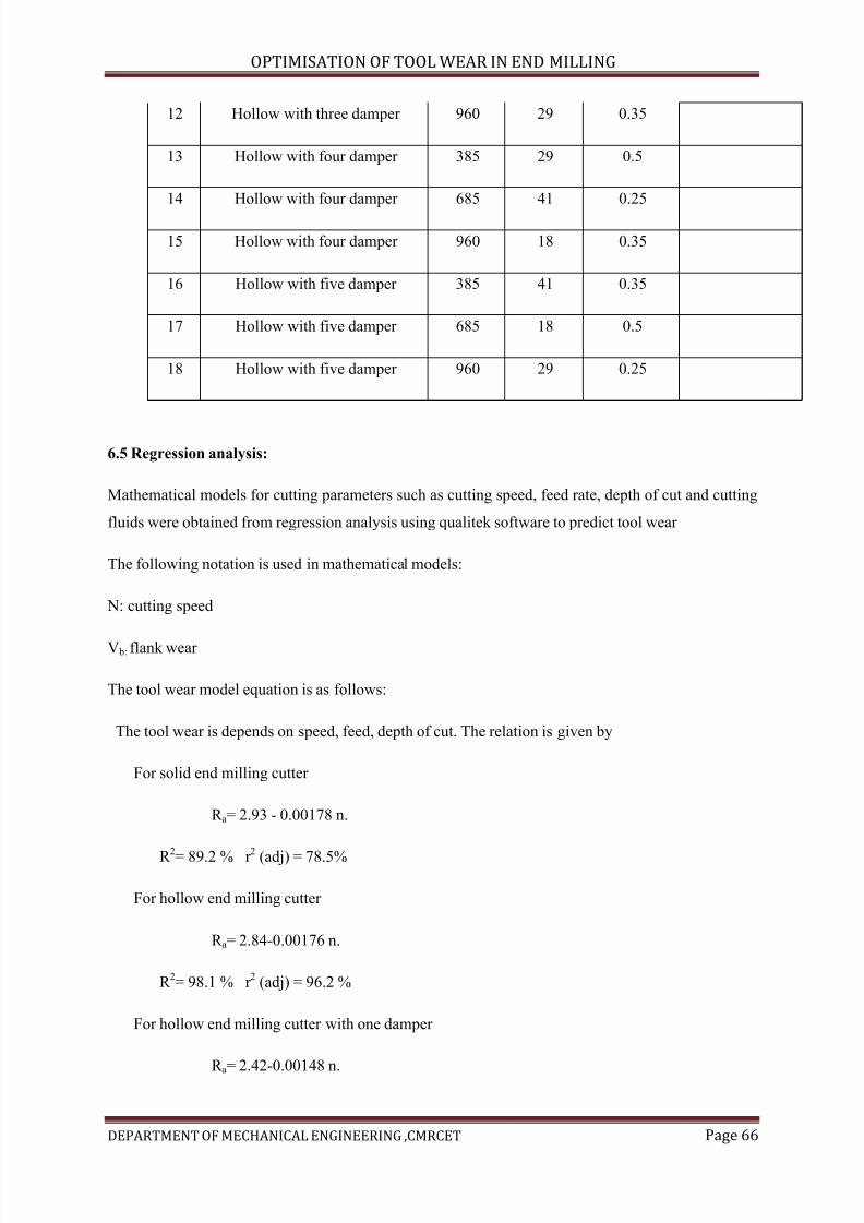
7/15/2019 Optimization of Tool Wear in End Milling
http://slidepdf.com/reader/full/optimization-of-tool-wear-in-end-milling 66/73
OPTIMISATION OF TOOL WEAR IN END MILLING
DEPARTMENT OF MECHANICAL ENGINEERING ,CMRCET Page 66
12 Hollow with three damper 960 29 0.35
13 Hollow with four damper 385 29 0.5
14 Hollow with four damper 685 41 0.25
15 Hollow with four damper 960 18 0.35
16 Hollow with five damper 385 41 0.35
17 Hollow with five damper 685 18 0.5
18 Hollow with five damper 960 29 0.25
6.5 Regression analysis:
Mathematical models for cutting parameters such as cutting speed, feed rate, depth of cut and cutting
fluids were obtained from regression analysis using qualitek software to predict tool wear
The following notation is used in mathematical models:
N: cutting speed
V b: flank wear
The tool wear model equation is as follows:
The tool wear is depends on speed, feed, depth of cut. The relation is given by
For solid end milling cutter
R a= 2.93 - 0.00178 n.
R 2
= 89.2 % r 2
(adj) = 78.5%
For hollow end milling cutter
R a= 2.84-0.00176 n.
R 2= 98.1 % r
2(adj) = 96.2 %
For hollow end milling cutter with one damper
R a= 2.42-0.00148 n.
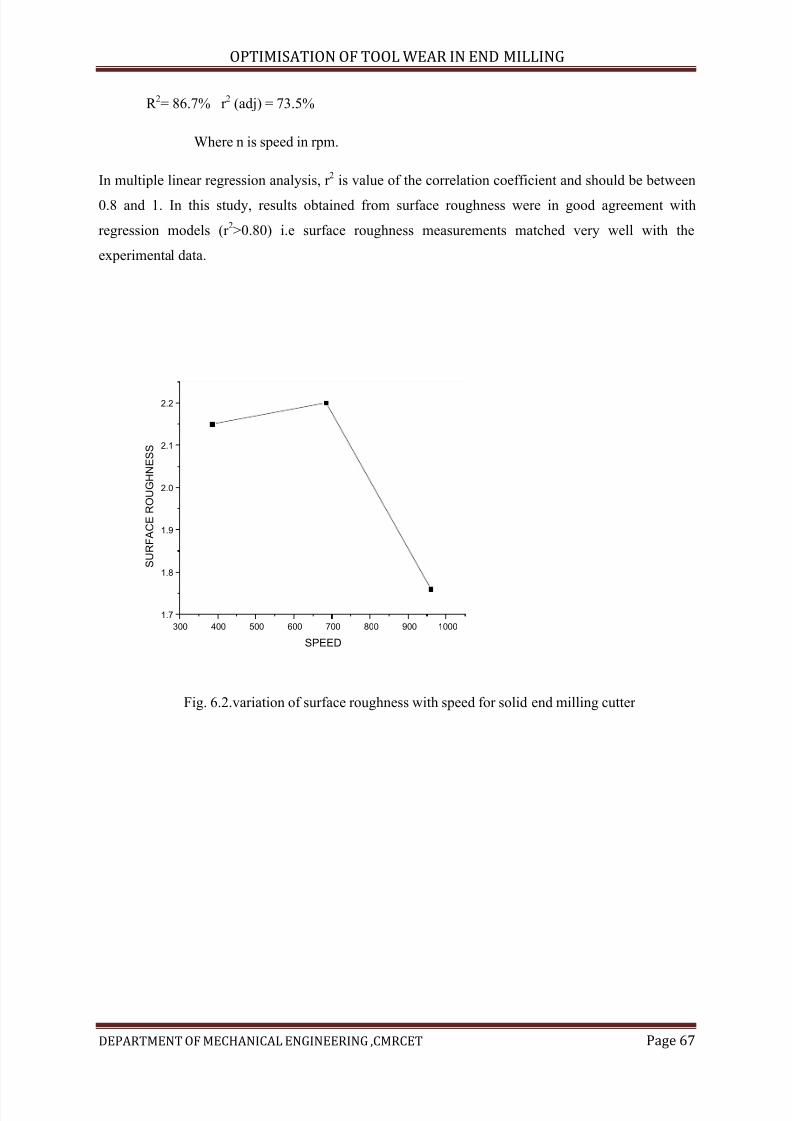
7/15/2019 Optimization of Tool Wear in End Milling
http://slidepdf.com/reader/full/optimization-of-tool-wear-in-end-milling 67/73
OPTIMISATION OF TOOL WEAR IN END MILLING
DEPARTMENT OF MECHANICAL ENGINEERING ,CMRCET Page 67
R 2= 86.7% r 2 (adj) = 73.5%
Where n is speed in rpm.
In multiple linear regression analysis, r 2
is value of the correlation coefficient and should be between
0.8 and 1. In this study, results obtained from surface roughness were in good agreement with
regression models (r 2>0.80) i.e surface roughness measurements matched very well with the
experimental data.
300 400 500 600 700 800 900 1000
1.7
1.8
1.9
2.0
2.1
2.2
S U R F A C E
R O U G H N E S S
SPEED
Fig. 6.2.variation of surface roughness with speed for solid end milling cutter
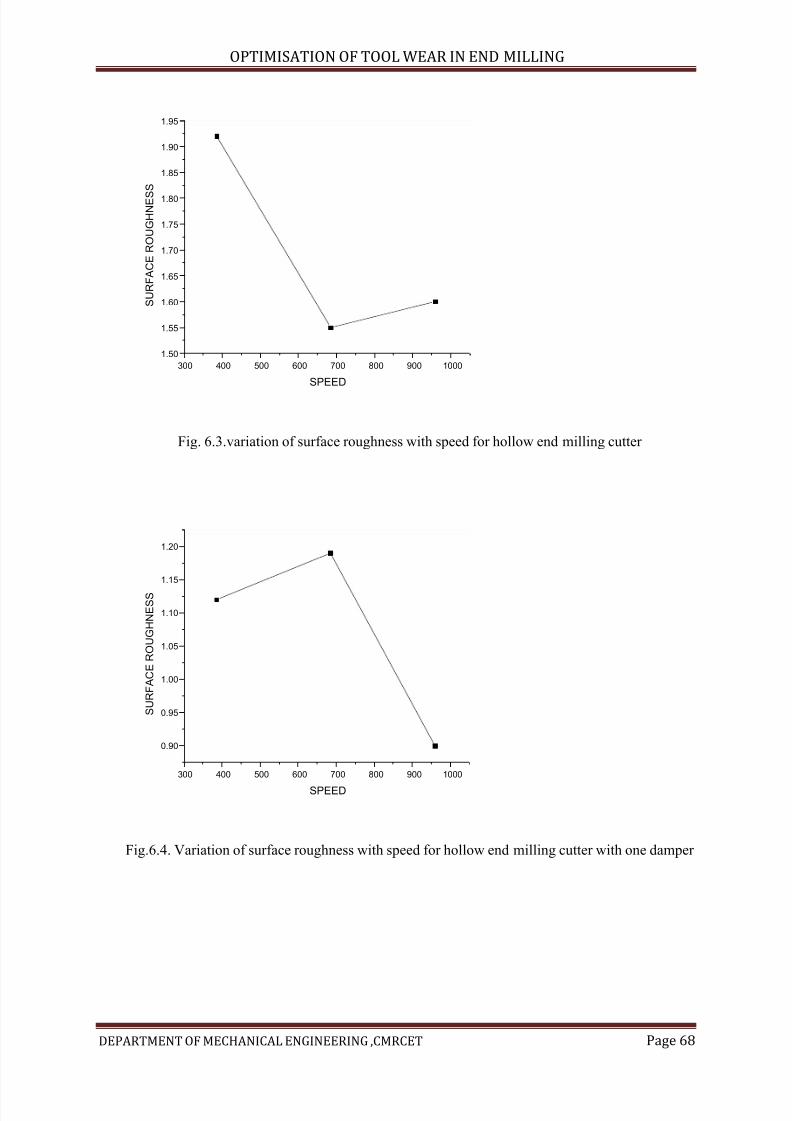
7/15/2019 Optimization of Tool Wear in End Milling
http://slidepdf.com/reader/full/optimization-of-tool-wear-in-end-milling 68/73
OPTIMISATION OF TOOL WEAR IN END MILLING
DEPARTMENT OF MECHANICAL ENGINEERING ,CMRCET Page 68
300 400 500 600 700 800 900 1000
1.50
1.55
1.60
1.65
1.70
1.75
1.80
1.85
1.90
1.95
S U R F A C E
R O U G H N E S
S
SPEED
Fig. 6.3.variation of surface roughness with speed for hollow end milling cutter
300 400 500 600 700 800 900 1000
0.90
0.95
1.00
1.05
1.10
1.15
1.20
S U R F A C E
R O U G H N E S S
SPEED
Fig.6.4. Variation of surface roughness with speed for hollow end milling cutter with one damper
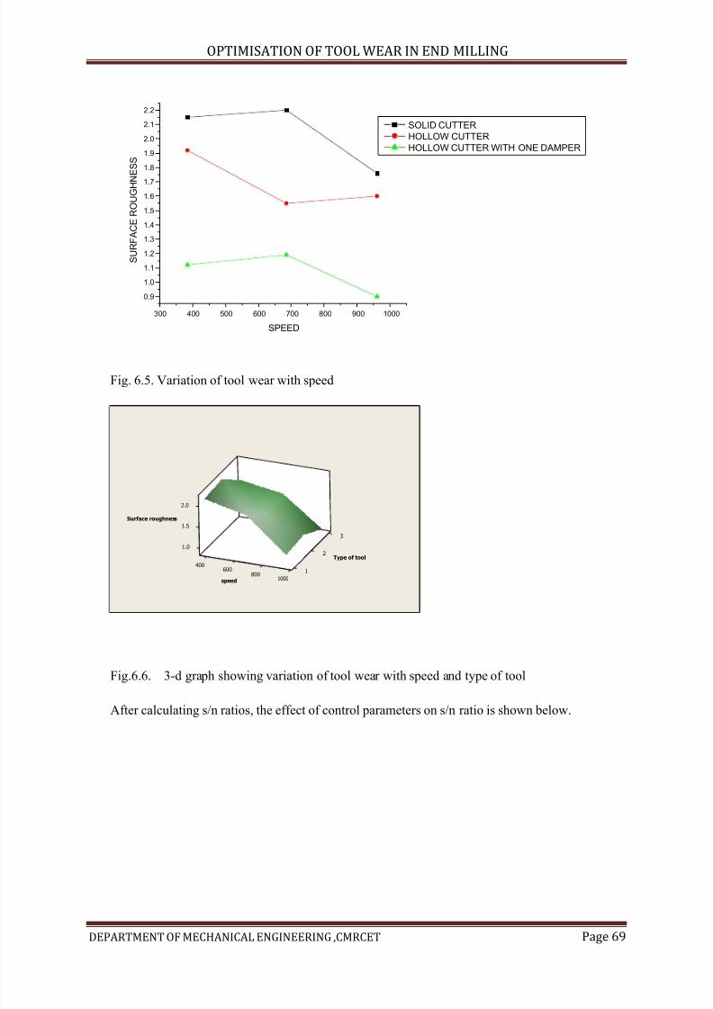
7/15/2019 Optimization of Tool Wear in End Milling
http://slidepdf.com/reader/full/optimization-of-tool-wear-in-end-milling 69/73
OPTIMISATION OF TOOL WEAR IN END MILLING
DEPARTMENT OF MECHANICAL ENGINEERING ,CMRCET Page 69
300 400 500 600 700 800 900 1000
0.9
1.0
1.1
1.2
1.3
1.4
1.5
1.6
1.7
1.8
1.9
2.0
2.1
2.2
SOLID CUTTER
HOLLOW CUTTER
HOLLOW CUTTER WITH ONE DAMPER
S U R F A C E
R O U G H N E S S
SPEED
Fig. 6.5. Variation of tool wear with speed
3
1.0
2
1.5
2.0
400600 1
8001000
Surface roughness
Type of tool
speed
Fig.6.6. 3-d graph showing variation of tool wear with speed and type of tool
After calculating s/n ratios, the effect of control parameters on s/n ratio is shown below.
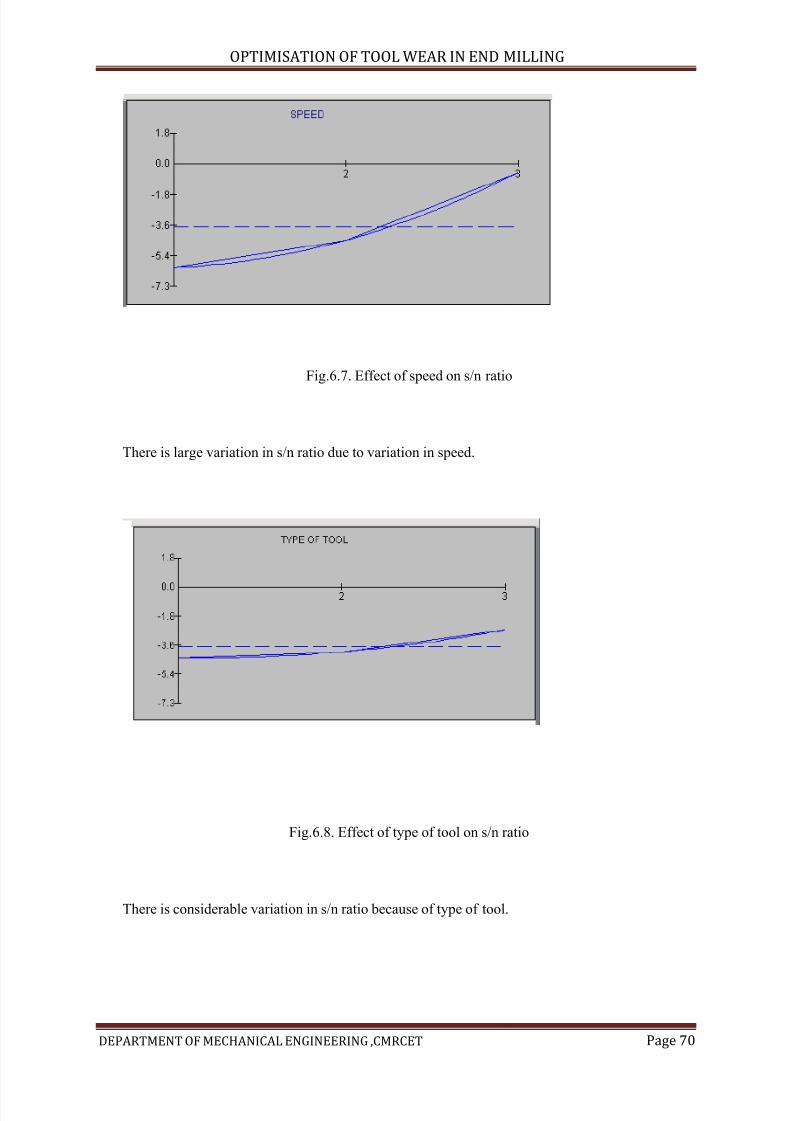
7/15/2019 Optimization of Tool Wear in End Milling
http://slidepdf.com/reader/full/optimization-of-tool-wear-in-end-milling 70/73
OPTIMISATION OF TOOL WEAR IN END MILLING
DEPARTMENT OF MECHANICAL ENGINEERING ,CMRCET Page 70
Fig.6.7. Effect of speed on s/n ratio
There is large variation in s/n ratio due to variation in speed.
Fig.6.8. Effect of type of tool on s/n ratio
There is considerable variation in s/n ratio because of type of tool.
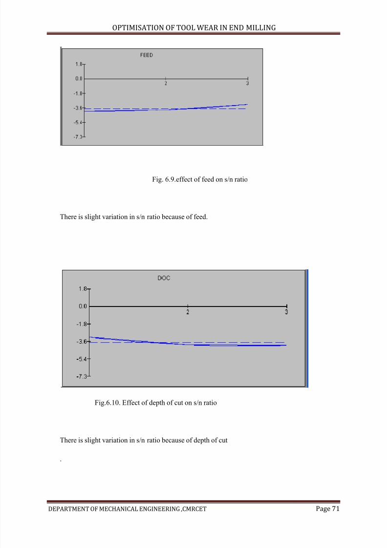
7/15/2019 Optimization of Tool Wear in End Milling
http://slidepdf.com/reader/full/optimization-of-tool-wear-in-end-milling 71/73
OPTIMISATION OF TOOL WEAR IN END MILLING
DEPARTMENT OF MECHANICAL ENGINEERING ,CMRCET Page 71
Fig. 6.9.effect of feed on s/n ratio
There is slight variation in s/n ratio because of feed.
Fig.6.10. Effect of depth of cut on s/n ratio
There is slight variation in s/n ratio because of depth of cut
.
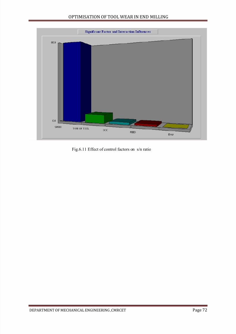
7/15/2019 Optimization of Tool Wear in End Milling
http://slidepdf.com/reader/full/optimization-of-tool-wear-in-end-milling 72/73
OPTIMISATION OF TOOL WEAR IN END MILLING
DEPARTMENT OF MECHANICAL ENGINEERING ,CMRCET Page 72
Fig.6.11 Effect of control factors on s/n ratio
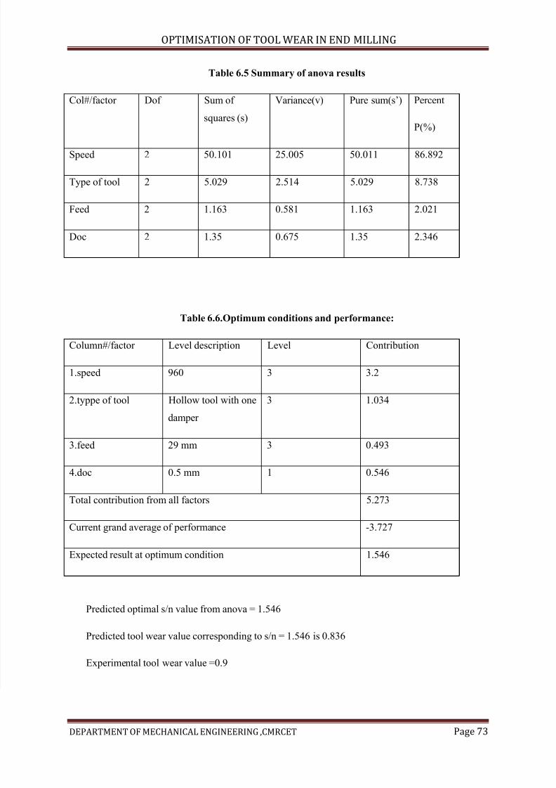
7/15/2019 Optimization of Tool Wear in End Milling
http://slidepdf.com/reader/full/optimization-of-tool-wear-in-end-milling 73/73
OPTIMISATION OF TOOL WEAR IN END MILLING
Table 6.5 Summary of anova results
Col#/factor Dof Sum of
squares (s)
Variance(v) Pure sum(s’) Percent
P(%)
Speed 2 50.101 25.005 50.011 86.892
Type of tool 2 5.029 2.514 5.029 8.738
Feed 2 1.163 0.581 1.163 2.021
Doc 2 1.35 0.675 1.35 2.346
Table 6.6.Optimum conditions and performance:
Column#/factor Level description Level Contribution
1.speed 960 3 3.2
2.typpe of tool Hollow tool with one
damper
3 1.034
3.feed 29 mm 3 0.493
4.doc 0.5 mm 1 0.546
Total contribution from all factors 5.273
Current grand average of performance -3.727
Expected result at optimum condition 1.546
P di t d ti l / l f 1 546


![Optimization of Milling Process Parameters using Taguchi ...[1] Optimization of gadget parameters of CNC Milling device for moderate metal using Taguchi layout and Single to Noise](https://img.pdfslide.net/doc/110x75/5ebc5074cce4ae63170ccc7a/optimization-of-milling-process-parameters-using-taguchi-1-optimization-of.jpg)