Embed Size (px)
Citation preview
Optimize your grid availability.
Surprising benefits of battery
energy storage.
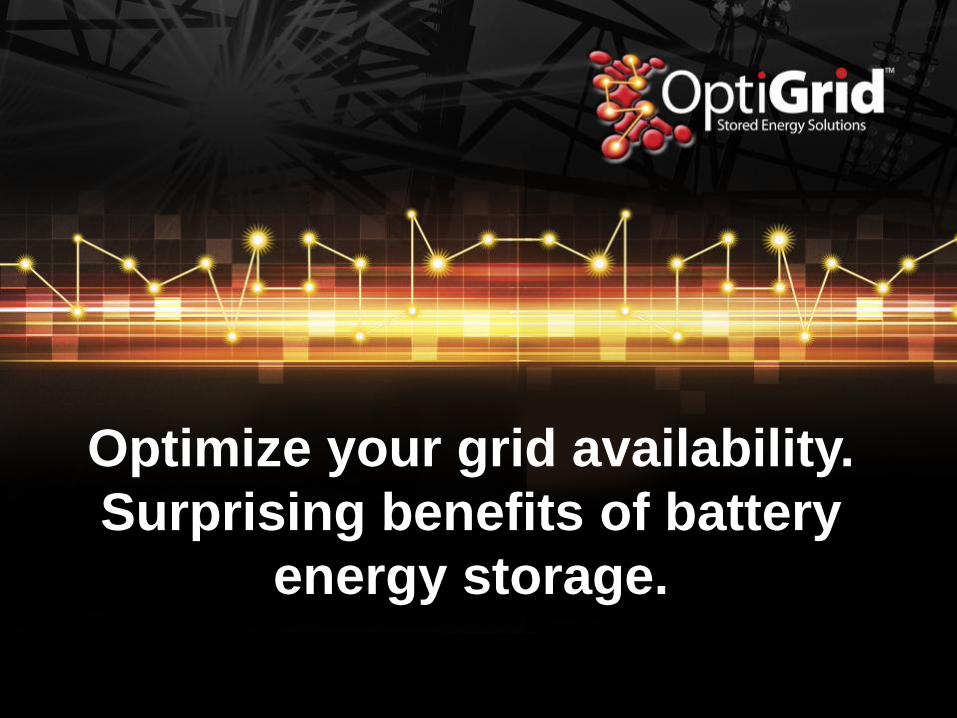
EnerSys® globally
2/7/2014
Page 2
Industrial battery manufacturer:
Reserve Power, Motive Power, Aerospace & Defense
9.800 employees (November 2013)
Sales approximately $2,28 billion in 2013
Over 10.000 customers in over 100 countries
HQ in Reading, Pennsylvania, USA.
30 manufacturing facilities in USA, EMEA and Asia
Global leader: 23% share in a $8.8 billion market in CY 2012
Includes Motive Power and Reserve Power only
Content
1. Availability versus reliability
2. Availability “legs”
3. Energy storage system (ESS)
4. ESS operational functions
5. Network related issues
6. ESS benefits
7. ESS locations
8. ESS reliability
9. Summary
Main systems criteria
• Safety
– Human
– Environment
– System
• Correct functions
• Availability
1. Availability versus
reliability
2. Availability “legs”
3. Energy storage
system (ESS)
4. ESS operational
functions
5. Network related
issues
6. ESS benefits
7. Ess locations
8. ESS reliability
9. Summary
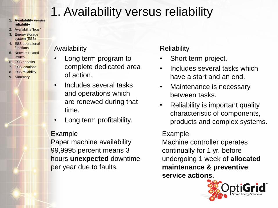
1. Availability versus reliability
Availability
• Long term program to
complete dedicated area
of action.
• Includes several tasks
and operations which
are renewed during that
time.
• Long term profitability.
1. Availability versus
reliability
2. Availability “legs”
3. Energy storage
system (ESS)
4. ESS operational
functions
5. Network related
issues
6. ESS benefits
7. ESS locations
8. ESS reliability
9. Summary
Reliability
• Short term project.
• Includes several tasks which
have a start and an end.
• Maintenance is necessary
between tasks.
• Reliability is important quality
characteristic of components,
products and complex systems.
Example
Machine controller operates
continually for 1 yr. before
undergoing 1 week of allocated
maintenance & preventive
service actions.
Example
Paper machine availability
99,9995 percent means 3
hours unexpected downtime
per year due to faults.
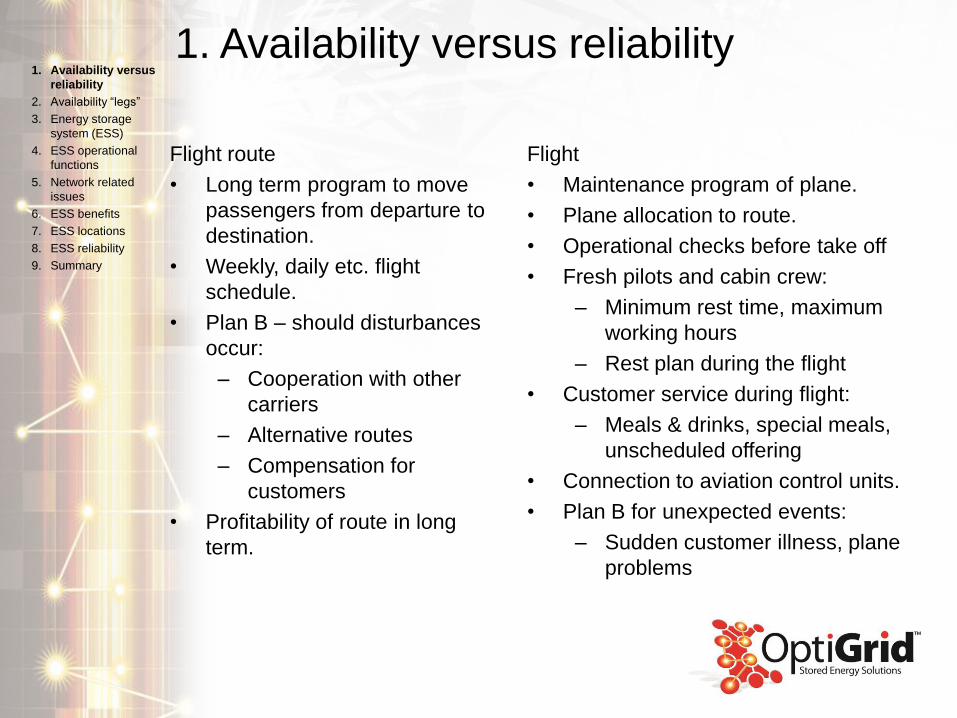
1. Availability versus reliability
Flight route
• Long term program to move
passengers from departure to
destination.
• Weekly, daily etc. flight
schedule.
• Plan B – should disturbances
occur:
– Cooperation with other
carriers
– Alternative routes
– Compensation for
customers
• Profitability of route in long
term.
1. Availability versus
reliability
2. Availability “legs”
3. Energy storage
system (ESS)
4. ESS operational
functions
5. Network related
issues
6. ESS benefits
7. ESS locations
8. ESS reliability
9. Summary
Flight
• Maintenance program of plane.
• Plane allocation to route.
• Operational checks before take off
• Fresh pilots and cabin crew:
– Minimum rest time, maximum
working hours
– Rest plan during the flight
• Customer service during flight:
– Meals & drinks, special meals,
unscheduled offering
• Connection to aviation control units.
• Plan B for unexpected events:
– Sudden customer illness, plane
problems
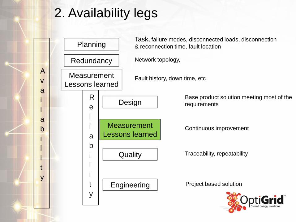
2. Availability legs
A
v
a
i
l
a
b
i
l
i
t
y
Planning
Redundancy
R
e
l
i
a
b
i
l
i
t
y
Measurement
Lessons learned
Design
Quality
Engineering
Measurement
Lessons learned
Base product solution meeting most of the
requirements
Continuous improvement
Traceability, repeatability
Project based solution
Task, failure modes, disconnected loads, disconnection
& reconnection time, fault location
Network topology,
Fault history, down time, etc
3. Energy storage system (ESS)
3a. Description.
3b. Types.
3c. Locations in grid.
3d. Components.
3e. Simplified electrical diagram.
3f. Modes of operation.
1. Availability versus
reliability
2. Availability “legs”
3. Energy storage
system (ESS)
4. ESS operational
functions
5. Network related
issues
6. ESS benefits
7. ESS locations
8. ESS reliability
9. Summary
3a. ESS description
• An ESS acts like a power plant, whilst also absorbing energy from
network.
• Both modes - charging and discharging – are operational
elements.
• An ESS features energy (kWh) and power (kW).
• Relation between energy and power equates to charging rate (C-
rate).
• Battery based energy storage reacts in tens of milliseconds.
1. Availability versus
reliability
2. Availability “legs”
3. Energy storage
system (ESS)
4. ESS operational
functions
5. Network related
issues
6. ESS benefits
7. ERSS locations
8. ESS reliability
9. Summary
3a. Description.
3b. Types.
3c. Locations in grid.
3d. Components.
3e. Simplified electrical
diagram.
3f. Modes of operation.
3b. ESS types
• Mechanical
– Pumped hydro
– Compressed air
– Fly wheel
– Thermal
• Chemical
– Power to gas
• Electro-chemical
– Redox flow
– Li-Ion
– Molten salt
– Lead acid
– And many, many more
1. Availability versus
reliability
2. Availability “legs”
3. Energy storage
system (ESS)
4. ESS operational
functions
5. Network related
issues
6. ESS benefits
7. ESS locations
8. ESS reliability
9. Summary
3a. Description.
3b. Types.
3c. Locations in grid.
3d. Components.
3e. Simplified electrical
diagram.
3f. Modes of operation.
3c. ESS locations in grid
• Power production: Balancing supply
– Wind farms
– PV parks
• Power transmission: Network support
– Frequency/ voltage support
– Black start
– Emergency power supply
• Power distribution: Capacity support
– Peak shaving/ shifting
– Fault-Ride Through (FRT)
• Power consumption: Optimizing energy use
– Peak shaving/ shifting
1. Availability versus
reliability
2. Availability “legs”
3. Energy storage
system (ESS)
4. ESS operational
functions
5. Network related
issues
6. ESS benefits
7. ESS locations
8. ESS reliability
9. Summary
3a. Description.
3b. Types.
3c. Locations in grid.
3d. Components.
3e. Simplified electrical
diagram.
3f. Modes of operation.
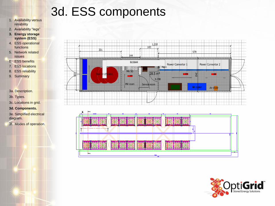
3d. ESS components1. Availability versus
reliability
2. Availability “legs”
3. Energy storage
system (ESS)
4. ESS operational
functions
5. Network related
issues
6. ESS benefits
7. ESS locations
8. ESS reliability
9. Summary
3a. Description.
3b. Types.
3c. Locations in grid.
3d. Components.
3e. Simplified electrical
diagram.
3f. Modes of operation.
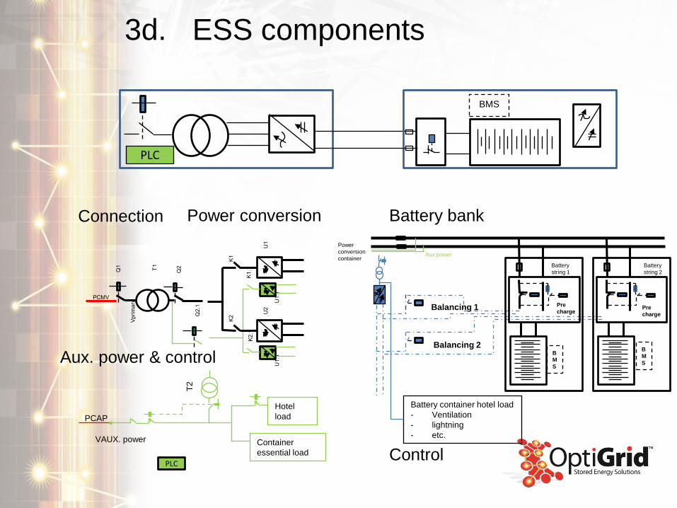
3d. ESS components
PLC
BMS
Q1
PCMV
T1
Q2
Vp
rim
ary
Q2
.1
K1
K2
K1
.1K
2.1
U1
U2
U1.1
U1.1
PLC
VAUX. power
PCAP
T2
Hotel
load
Container
essential load
Balancing 1
Balancing 2
Battery container hotel load
- Ventilation
- lightning
- etc.
B
M
S
Pre
chargePre
charge
Battery
string 1
Battery
string 2
Aux power
Power
conversion
container
B
M
S
Connection Power conversion
Aux. power & control
Battery bank
Control

3e. Simplified electrical diagram
BM
S
BM
S
UPS
Q1
K1
K2
K1.1
K2.1
U1
U2
U1.1
U2.1
K3 K4
K5
K5.1
PLC
Communication to SCADA
BMS, inverters and controlling
Relays K3-4
Power supply from UPS
K6S5
Energy for BMS, inverters
electronics and other essential
auxiliary circuits
0,4 kV
558 VK3.1
K4.
1
PCBT
PCMT
AuxServices (cooling,
etc)
SCADA
T1
T2
(*(*
(*
(* Interlocking
Q2
20 kV
1. Availability versus
reliability
2. Availability “legs”
3. Energy storage
system (ESS)
4. ESS operational
functions
5. Network related
issues
6. ESS benefits
7. ESS locations
8. ESS reliability
9. Summary
3a. Description.
3b. Types.
3c. Locations in grid.
3d. Components.
3e. Simplified electrical
diagram.
3f. Modes of operation.
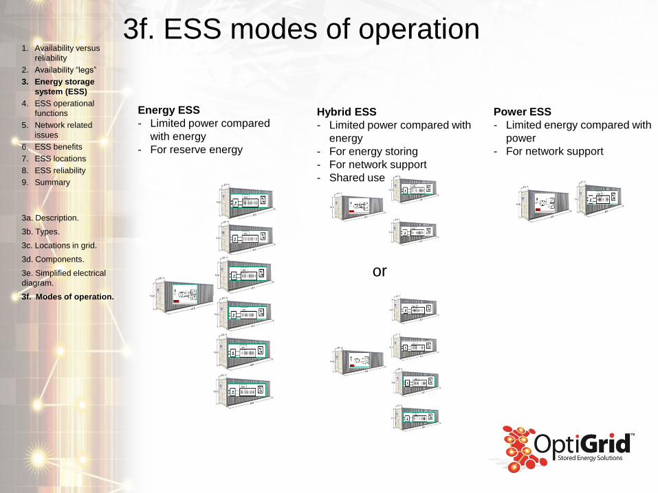
3f. ESS modes of operation
Energy ESS
- Limited power compared
with energy
- For reserve energy
Hybrid ESS
- Limited power compared with
energy
- For energy storing
- For network support
- Shared use
Power ESS
- Limited energy compared with
power
- For network support
or
1. Availability versus
reliability
2. Availability “legs”
3. Energy storage
system (ESS)
4. ESS operational
functions
5. Network related
issues
6. ESS benefits
7. ESS locations
8. ESS reliability
9. Summary
3a. Description.
3b. Types.
3c. Locations in grid.
3d. Components.
3e. Simplified electrical
diagram.
3f. Modes of operation.
4. ESS operational functions
4a. Reactive power support
4b. Frequency and voltage support
4c. Peak shaving and shifting
4d. Fault Ride Trough support
1. Availability versus
reliability
2. Availability “legs”
3. Energy storage
system (ESS)
4. ESS operational
functions
5. Network related
issues
6. ESS benefits
7. ESS locations
8. ESS reliability
9. Summary

Power controller
• During normal operation energy
storage absorbs and feeds energy to
network.
• There is power and reactive current.
• Semiconductor operation has different
switching frequency
• As such operation model is not round.
1. Availability versus
reliability
2. Availability “legs”
3. Energy storage
system (ESS)
4. ESS operational
functions
5. Network related
issues
6. ESS benefits
7. ESS locations
8. ESS reliability
9. Summary
4a. Reactive power
support
4b. Frequency and
voltage support
4c. Peak shaving and
shifting
4d. Fault-Ride Through
support
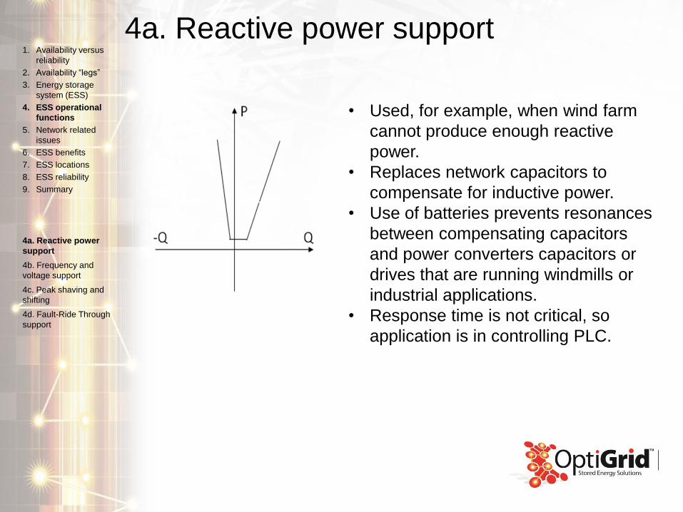
4a. Reactive power support
• Used, for example, when wind farm
cannot produce enough reactive
power.
• Replaces network capacitors to
compensate for inductive power.
• Use of batteries prevents resonances
between compensating capacitors
and power converters capacitors or
drives that are running windmills or
industrial applications.
• Response time is not critical, so
application is in controlling PLC.
1. Availability versus
reliability
2. Availability “legs”
3. Energy storage
system (ESS)
4. ESS operational
functions
5. Network related
issues
6. ESS benefits
7. ESS locations
8. ESS reliability
9. Summary
4a. Reactive power
support
4b. Frequency and
voltage support
4c. Peak shaving and
shifting
4d. Fault-Ride Through
support
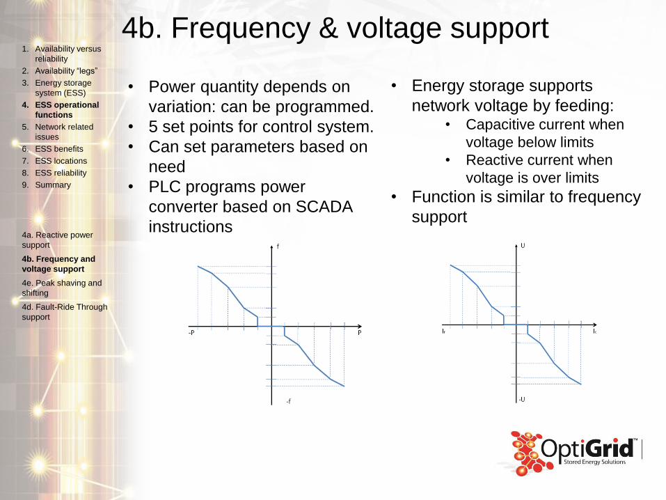
4b. Frequency & voltage support
• Power quantity depends on
variation: can be programmed.
• 5 set points for control system.
• Can set parameters based on
need
• PLC programs power
converter based on SCADA
instructions
• Energy storage supports
network voltage by feeding:• Capacitive current when
voltage below limits
• Reactive current when
voltage is over limits
• Function is similar to frequency
support
1. Availability versus
reliability
2. Availability “legs”
3. Energy storage
system (ESS)
4. ESS operational
functions
5. Network related
issues
6. ESS benefits
7. ESS locations
8. ESS reliability
9. Summary
4a. Reactive power
support
4b. Frequency and
voltage support
4e. Peak shaving and
shifting
4d. Fault-Ride Through
support
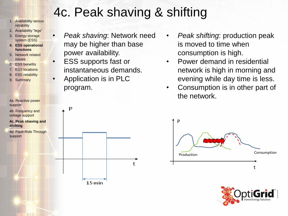
4c. Peak shaving & shifting
• Peak shaving: Network need
may be higher than base
power availability.
• ESS supports fast or
instantaneous demands.
• Application is in PLC
program.
• Peak shifting: production peak
is moved to time when
consumption is high.
• Power demand in residential
network is high in morning and
evening while day time is less.
• Consumption is in other part of
the network.
1. Availability versus
reliability
2. Availability “legs”
3. Energy storage
system (ESS)
4. ESS operational
functions
5. Network related
issues
6. ESS benefits
7. ESS locations
8. ESS reliability
9. Summary
4a. Reactive power
support
4b. Frequency and
voltage support
4c. Peak shaving and
shifting
4d. Fault-Ride Through
support

4d. Fault-ride through (FRT)
• FRT function allows
user to customize
voltage ride through
behavior to meet grid
code requirements.
ESS Voltage
Icapacitive
max
Iinductive
max
Vfer
I
V
1. Availability versus
reliability
2. Availability “legs”
3. Energy storage
system (ESS)
4. ESS operational
functions
5. Network related
issues
6. ESS benefits
7. ESS locations
8. ESS reliability
9. Summary
4a. Reactive power
support
4b. Frequency and
voltage support
4c. Peak shaving and
shifting
4d. Fault-Ride Through
support
5. Network related issues
5a. Redundancy: normal operation
5b. Redundancy: T2 fails, switchgear operation
5c. Planning: normal operation
5d. Voltage support in long distribution lines
1. Availability versus
reliability
2. Availability “legs”
3. Energy storage
system (ESS)
4. ESS operational
functions
5. Network related
issues
6. ESS benefits
7. ESS locations
8. ESS reliability
9. Summary
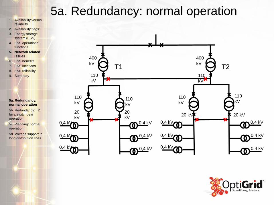
5a. Redundancy: normal operation
110
kV
20 kV
110
kV
20 kV
0,4 kV
0,4 kV
0,4 kV
0,4 kV
0,4 kV
0,4 kV
110
kV
20
kV
110
kV
20
kV0,4 kV
0,4 kV
0,4 kV
0,4 kV
0,4 kV
0,4 kV
110
kV
110
kV
400
kV
400
kVT1 T2
1. Availability versus
reliability
2. Availability “legs”
3. Energy storage
system (ESS)
4. ESS operational
functions
5. Network related
issues
6. ESS benefits
7. ESS locations
8. ESS reliability
9. Summary
5a. Redundancy:
normal operation
5b. Redundancy: T2
fails, switchgear
operation
5c. Planning: normal
operation
5d. Voltage support in
long distribution lines
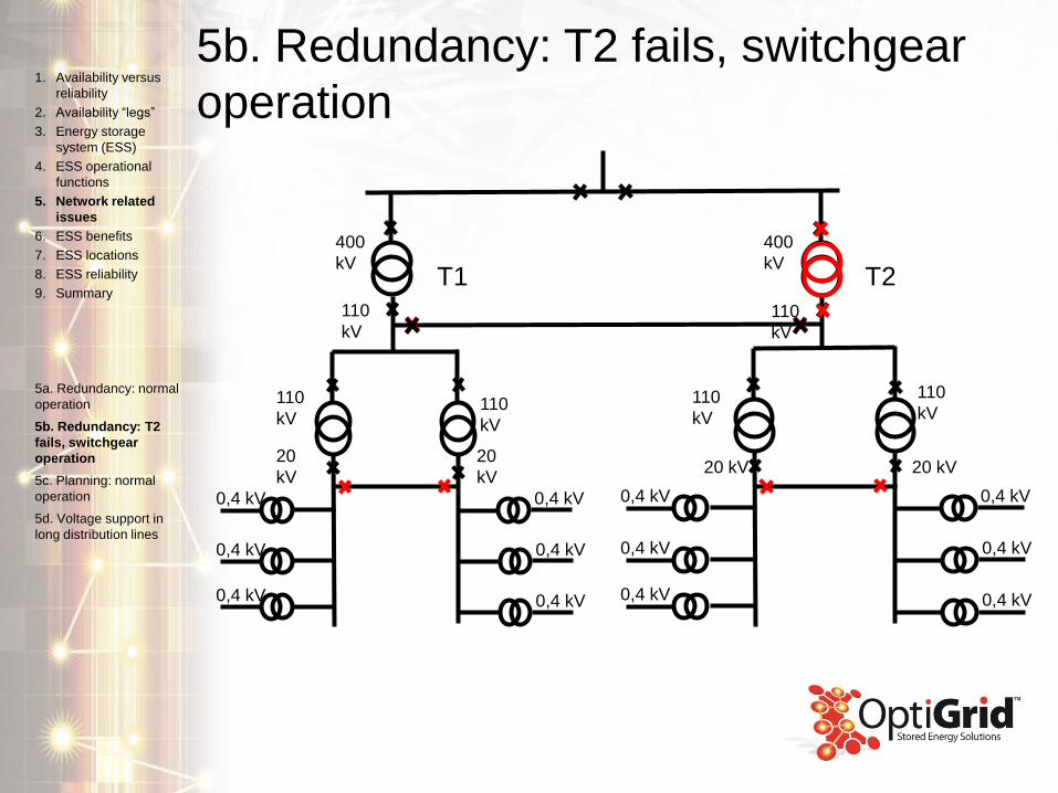
5b. Redundancy: T2 fails, switchgear
operation
110
kV
20 kV
110
kV
20 kV
0,4 kV
0,4 kV
0,4 kV
0,4 kV
0,4 kV
0,4 kV
110
kV
20
kV
110
kV
20
kV
0,4 kV
0,4 kV
0,4 kV
0,4 kV
0,4 kV
0,4 kV
110
kV
110
kV
400
kV
400
kVT1 T2
1. Availability versus
reliability
2. Availability “legs”
3. Energy storage
system (ESS)
4. ESS operational
functions
5. Network related
issues
6. ESS benefits
7. ESS locations
8. ESS reliability
9. Summary
5a. Redundancy: normal
operation
5b. Redundancy: T2
fails, switchgear
operation
5c. Planning: normal
operation
5d. Voltage support in
long distribution lines
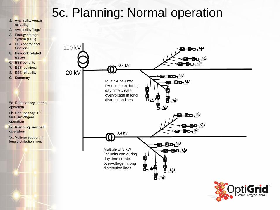
5c. Planning: Normal operation
110 kV
20 kV
Multiple of 3 kW
PV units can during
day time create
overvoltage in long
distribution lines
0,4 kV
Multiple of 3 kW
PV units can during
day time create
overvoltage in long
distribution lines
0,4 kV
1. Availability versus
reliability
2. Availability “legs”
3. Energy storage
system (ESS)
4. ESS operational
functions
5. Network related
issues
6. ESS benefits
7. ESS locations
8. ESS reliability
9. Summary
5a. Redundancy: normal
operation
5b. Redundancy: T2
fails, switchgear
operation
5c. Planning: normal
operation
5d. Voltage support in
long distribution lines

5d. Voltage support in long distribution
lines
• When distribution line is long,
daily voltage variation is
significant.
• Voltage at start of line remains
stable.
• During day time consumption
is low, but PV solar peaks –
causes significant voltage rise.
• During evening no PV
production, but consumption is
high.
• This can lead to voltage drop
below limits.
V
+ 10 %
- 10 %
DistanceUN
1. Availability versus
reliability
2. Availability “legs”
3. Energy storage
system (ESS)
4. ESS operational
functions
5. Network related
issues
6. ESS benefits
7. ESS locations
8. ESS reliability
9. Summary
5a. Redundancy: normal
operation
5b. Redundancy: T2
fails, switchgear
operation
5c. Planning: normal
operation
5d. Voltage support in
long distribution lines
6. ESS benefits
6a. Minimal disturbance during transformer failure
6b. Shared use
6c. Speed up emergency power availability
6d. Voltage support with long MV distribution line
6e. Voltage support in LV distribution line
6f. Energy storage locations
1. Availability versus
reliability
2. Availability “legs”
3. Energy storage
system (ESS)
4. ESS operational
functions
5. Network related
issues
6. ESS benefits
7. ESS locations
8. ESS reliability
9. Summary
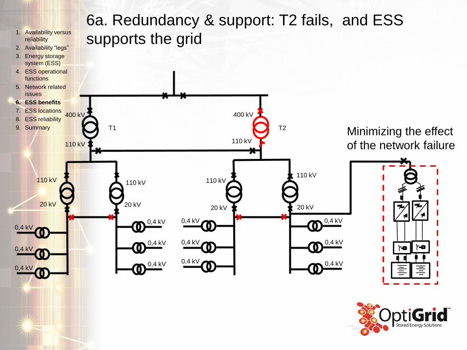
6a. Redundancy & support: T2 fails, and ESS
supports the grid1. Availability versus
reliability
2. Availability “legs”
3. Energy storage
system (ESS)
4. ESS operational
functions
5. Network related
issues
6. ESS benefits
7. ESS locations
8. ESS reliability
9. Summary
110 kV
20 kV
110 kV
20 kV
0,4 kV
0,4 kV
0,4 kV
0,4 kV
0,4 kV
0,4 kV
110 kV
20 kV
110 kV
20 kV
0,4 kV
0,4 kV
0,4 kV
110 kV110 kV
400 kV400 kV
T1 T2
0,4 kV
0,4 kV
0,4 kV
Minimizing the effect
of the network failure
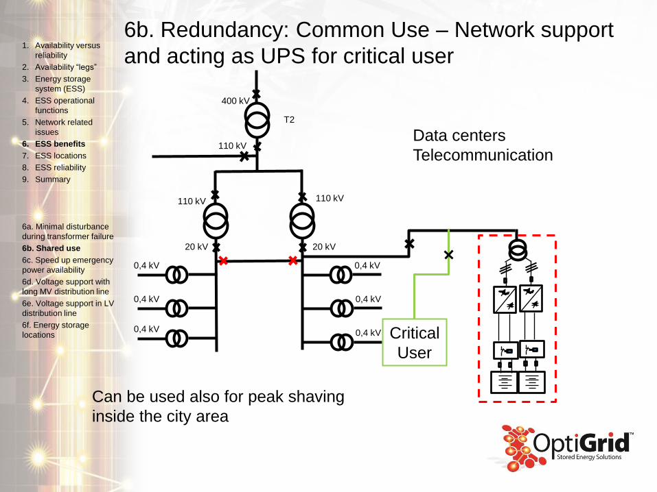
6b. Redundancy: Common Use – Network support
and acting as UPS for critical user1. Availability versus
reliability
2. Availability “legs”
3. Energy storage
system (ESS)
4. ESS operational
functions
5. Network related
issues
6. ESS benefits
7. ESS locations
8. ESS reliability
9. Summary
6a. Minimal disturbance
during transformer failure
6b. Shared use
6c. Speed up emergency
power availability
6d. Voltage support with
long MV distribution line
6e. Voltage support in LV
distribution line
6f. Energy storage
locations
110 kV
20 kV
110 kV
20 kV
0,4 kV
0,4 kV
0,4 kV
0,4 kV
0,4 kV
0,4 kV
110 kV
400 kV
T2
Critical
User
Data centers
Telecommunication
Can be used also for peak shaving
inside the city area
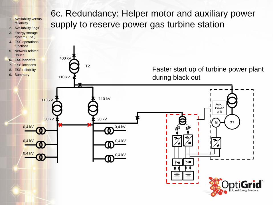
6c. Redundancy: Helper motor and auxiliary power
supply to reserve power gas turbine station1. Availability versus
reliability
2. Availability “legs”
3. Energy storage
system (ESS)
4. ESS operational
functions
5. Network related
issues
6. ESS benefits
7. ESS locations
8. ESS reliability
9. Summary
110 kV
20 kV
110 kV
20 kV
0,4 kV
0,4 kV
0,4 kV
0,4 kV
0,4 kV
0,4 kV
110 kV
400 kV
T2
M GT
Aux.
Power
unit
Faster start up of turbine power plant
during black out
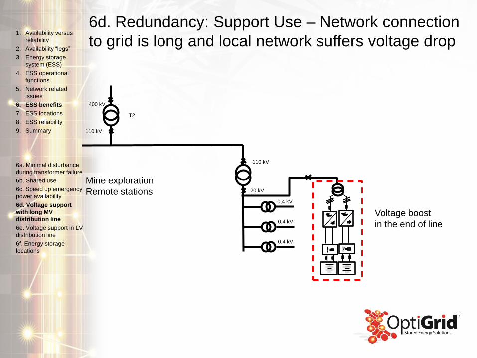
6d. Redundancy: Support Use – Network connection
to grid is long and local network suffers voltage drop1. Availability versus
reliability
2. Availability “legs”
3. Energy storage
system (ESS)
4. ESS operational
functions
5. Network related
issues
6. ESS benefits
7. ESS locations
8. ESS reliability
9. Summary
6a. Minimal disturbance
during transformer failure
6b. Shared use
6c. Speed up emergency
power availability
6d. Voltage support
with long MV
distribution line
6e. Voltage support in LV
distribution line
6f. Energy storage
locations
110 kV
20 kV
0,4 kV
0,4 kV
0,4 kV
400 kV
T2
110 kV
Mine exploration
Remote stations
Voltage boost
in the end of line
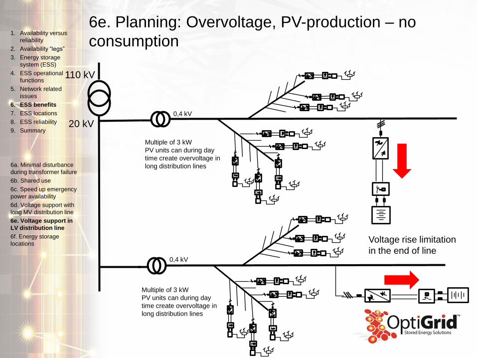
6e. Planning: Overvoltage, PV-production – no
consumption1. Availability versus
reliability
2. Availability “legs”
3. Energy storage
system (ESS)
4. ESS operational
functions
5. Network related
issues
6. ESS benefits
7. ESS locations
8. ESS reliability
9. Summary
6a. Minimal disturbance
during transformer failure
6b. Shared use
6c. Speed up emergency
power availability
6d. Voltage support with
long MV distribution line
6e. Voltage support in
LV distribution line
6f. Energy storage
locations
110 kV
20 kV
Multiple of 3 kW
PV units can during day
time create overvoltage in
long distribution lines
0,4 kV
Multiple of 3 kW
PV units can during day
time create overvoltage in
long distribution lines
0,4 kV
Voltage rise limitation
in the end of line
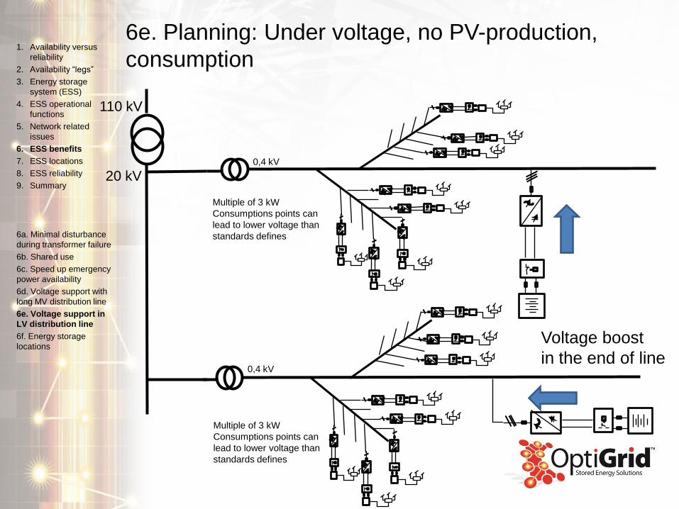
6e. Planning: Under voltage, no PV-production,
consumption1. Availability versus
reliability
2. Availability “legs”
3. Energy storage
system (ESS)
4. ESS operational
functions
5. Network related
issues
6. ESS benefits
7. ESS locations
8. ESS reliability
9. Summary
6a. Minimal disturbance
during transformer failure
6b. Shared use
6c. Speed up emergency
power availability
6d. Voltage support with
long MV distribution line
6e. Voltage support in
LV distribution line
6f. Energy storage
locations
110 kV
20 kV
0,4 kV
Multiple of 3 kW
Consumptions points can
lead to lower voltage than
standards defines
0,4 kV
Multiple of 3 kW
Consumptions points can
lead to lower voltage than
standards defines
Voltage boost
in the end of line
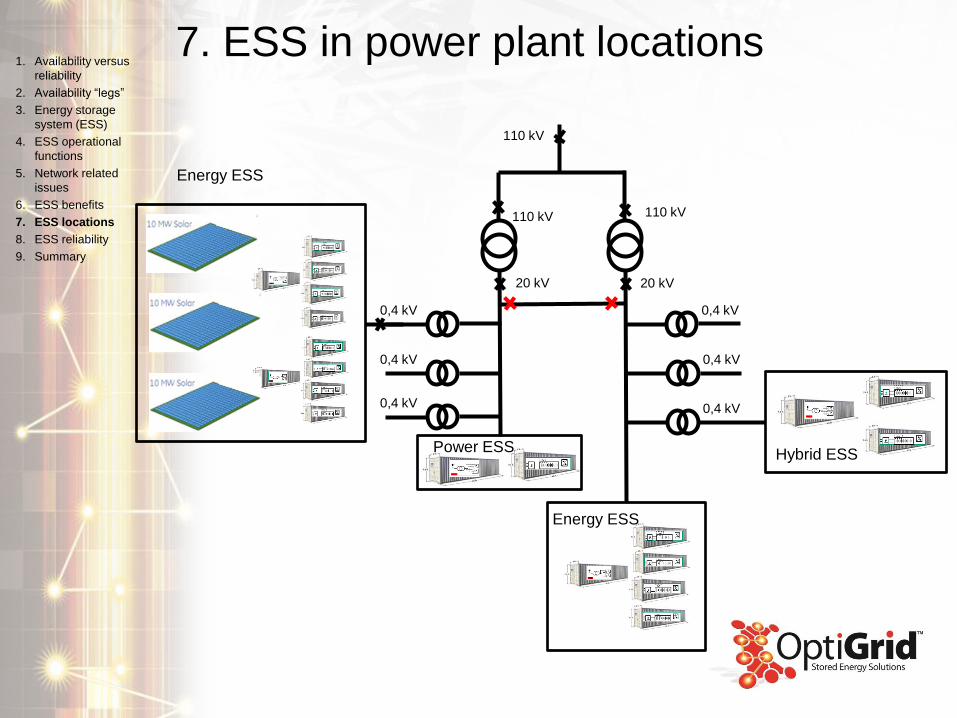
7. ESS in power plant locations1. Availability versus
reliability
2. Availability “legs”
3. Energy storage
system (ESS)
4. ESS operational
functions
5. Network related
issues
6. ESS benefits
7. ESS locations
8. ESS reliability
9. Summary
110 kV
20 kV
110 kV
20 kV
0,4 kV
0,4 kV
0,4 kV
0,4 kV
0,4 kV
0,4 kV
110 kV
Power ESS
Energy ESS
Energy ESS
Hybrid ESS
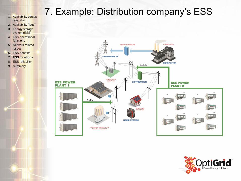
7. Example: Distribution company’s ESS1. Availability versus
reliability
2. Availability “legs”
3. Energy storage
system (ESS)
4. ESS operational
functions
5. Network related
issues
6. ESS benefits
7. ESS locations
8. ESS reliability
9. Summary
8. ESS reliability
8a. Support and construction
8b. Availability legs
8c. Design: High purity materials
8d. Design: AGM battery grids vs PowerSafe ® SBS pure lead grids
8e. Factors determining VRLA battery working life
8f. Thin plate pure lead grid: post corrosion test
8g. Reliability: redundancy
One inverter unit power train
8h. Engineering: On line balancing
8i. Engineering Power Plant Controller (PPC)
1. Availability versus
reliability
2. Availability “legs”
3. Energy storage
system (ESS)
4. ESS operational
functions
5. Network related
issues
6. ESS benefits
7. ESS locations
8. ESS reliability
9. Summary
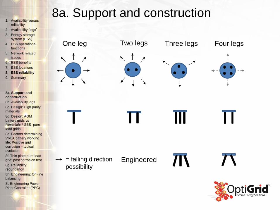
8a. Support and construction
One leg Two legs Three legs Four legs
= falling direction
possibilityEngineered
1. Availability versus
reliability
2. Availability “legs”
3. Energy storage
system (ESS)
4. ESS operational
functions
5. Network related
issues
6. ESS benefits
7. ESS locations
8. ESS reliability
9. Summary
8a. Support and
construction
8b. Availability legs
8c. Design: High purity
materials
8d. Design: AGM
battery grids vs
PowerSafe ® SBS pure
lead grids
8e. Factors determining
VRLA battery working
life: Positive grid
corrosion – typical
evolution
8f. Thin plate pure lead
grid: post corrosion test
8g. Reliability:
redundancy
8h. Engineering: On-line
balancing
8i. Engineering Power
Plant Controller (PPC)
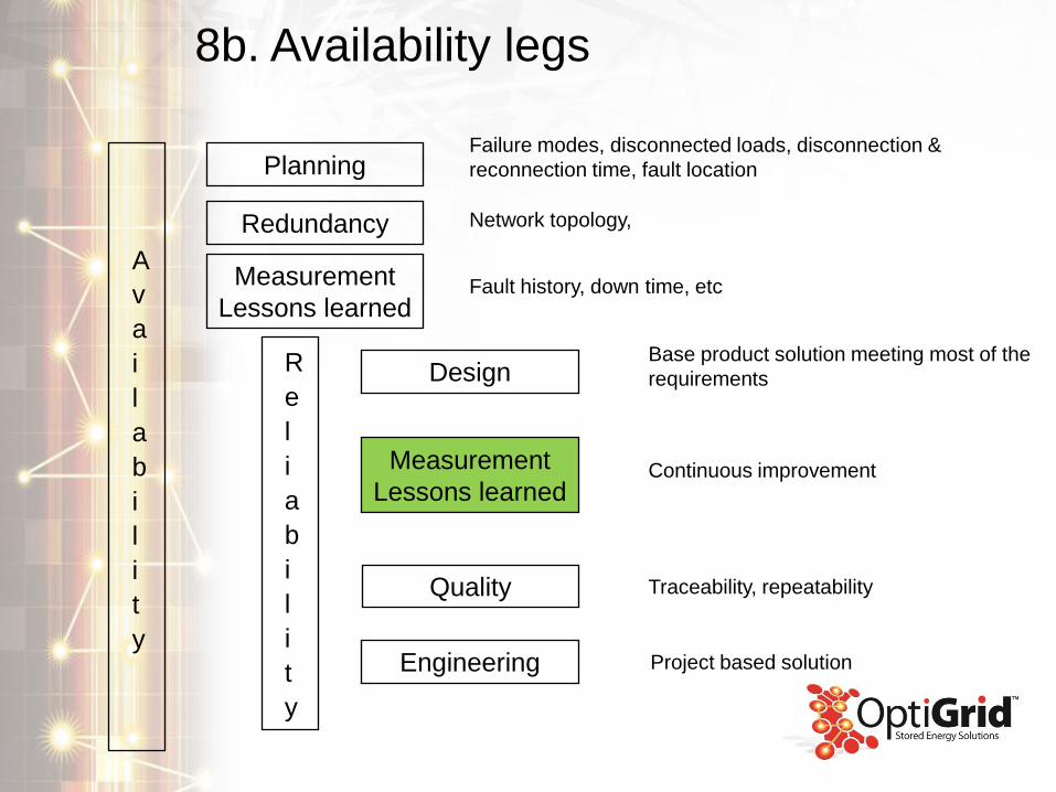
8b. Availability legs
A
v
a
i
l
a
b
i
l
i
t
y
Planning
Redundancy
R
e
l
i
a
b
i
l
i
t
y
Measurement
Lessons learned
Design
Quality
Engineering
Measurement
Lessons learned
Base product solution meeting most of the
requirements
Continuous improvement
Traceability, repeatability
Project based solution
Failure modes, disconnected loads, disconnection &
reconnection time, fault location
Network topology,
Fault history, down time, etc
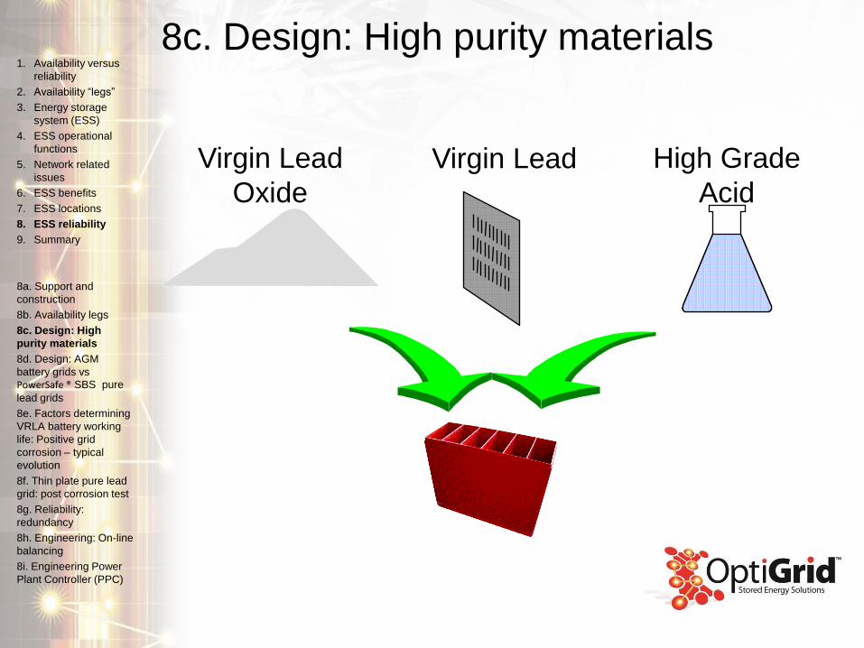
Virgin Lead
Oxide
High Grade
Acid
Virgin Lead
8c. Design: High purity materials1. Availability versus
reliability
2. Availability “legs”
3. Energy storage
system (ESS)
4. ESS operational
functions
5. Network related
issues
6. ESS benefits
7. ESS locations
8. ESS reliability
9. Summary
8a. Support and
construction
8b. Availability legs
8c. Design: High
purity materials
8d. Design: AGM
battery grids vs
PowerSafe ® SBS pure
lead grids
8e. Factors determining
VRLA battery working
life: Positive grid
corrosion – typical
evolution
8f. Thin plate pure lead
grid: post corrosion test
8g. Reliability:
redundancy
8h. Engineering: On-line
balancing
8i. Engineering Power
Plant Controller (PPC)
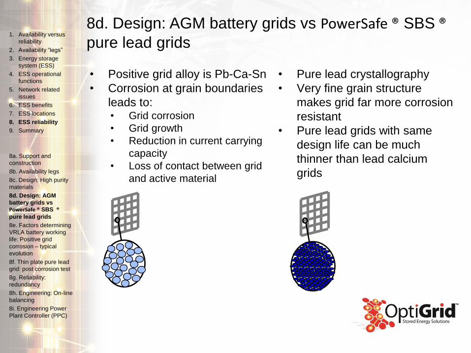
• Positive grid alloy is Pb-Ca-Sn
• Corrosion at grain boundaries
leads to:• Grid corrosion
• Grid growth
• Reduction in current carrying
capacity
• Loss of contact between grid
and active material
8d. Design: AGM battery grids vs PowerSafe ® SBS ®pure lead grids
• Pure lead crystallography
• Very fine grain structure
makes grid far more corrosion
resistant
• Pure lead grids with same
design life can be much
thinner than lead calcium
grids
1. Availability versus
reliability
2. Availability “legs”
3. Energy storage
system (ESS)
4. ESS operational
functions
5. Network related
issues
6. ESS benefits
7. ESS locations
8. ESS reliability
9. Summary
8a. Support and
construction
8b. Availability legs
8c. Design: High purity
materials
8d. Design: AGM
battery grids vs
PowerSafe ® SBS ®pure lead grids
8e. Factors determining
VRLA battery working
life: Positive grid
corrosion – typical
evolution
8f. Thin plate pure lead
grid: post corrosion test
8g. Reliability:
redundancy
8h. Engineering: On-line
balancing
8i. Engineering Power
Plant Controller (PPC)
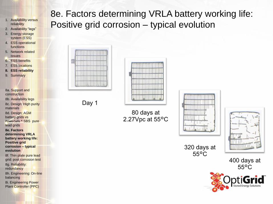
8e. Factors determining VRLA battery working life:
Positive grid corrosion – typical evolution
Day 1
80 days at 2.27Vpc at 55°C
320 days at 55°C
400 days at 55°C
1. Availability versus
reliability
2. Availability “legs”
3. Energy storage
system (ESS)
4. ESS operational
functions
5. Network related
issues
6. ESS benefits
7. ESS locations
8. ESS reliability
9. Summary
8a. Support and
construction
8b. Availability legs
8c. Design: High purity
materials
8d. Design: AGM
battery grids vs
PowerSafe ® SBS pure
lead grids
8e. Factors
determining VRLA
battery working life:
Positive grid
corrosion – typical
evolution
8f. Thin plate pure lead
grid: post corrosion test
8g. Reliability:
redundancy
8h. Engineering: On-line
balancing
8i. Engineering Power
Plant Controller (PPC)
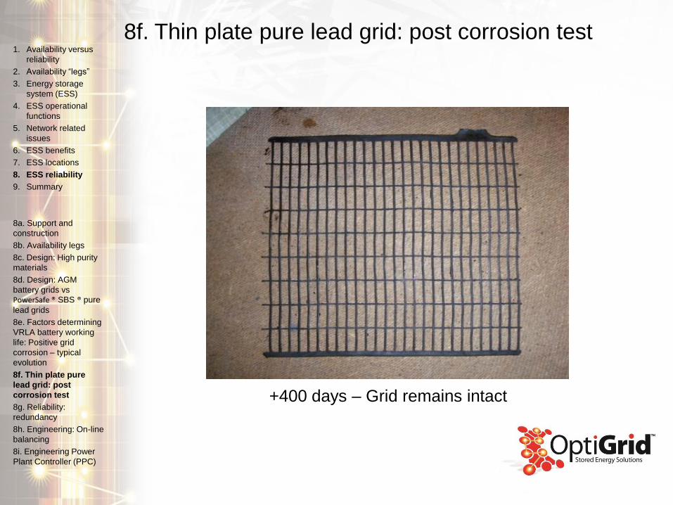
8f. Thin plate pure lead grid: post corrosion test
+400 days – Grid remains intact
1. Availability versus
reliability
2. Availability “legs”
3. Energy storage
system (ESS)
4. ESS operational
functions
5. Network related
issues
6. ESS benefits
7. ESS locations
8. ESS reliability
9. Summary
8a. Support and
construction
8b. Availability legs
8c. Design: High purity
materials
8d. Design: AGM
battery grids vs
PowerSafe ® SBS ® pure
lead grids
8e. Factors determining
VRLA battery working
life: Positive grid
corrosion – typical
evolution
8f. Thin plate pure
lead grid: post
corrosion test
8g. Reliability:
redundancy
8h. Engineering: On-line
balancing
8i. Engineering Power
Plant Controller (PPC)
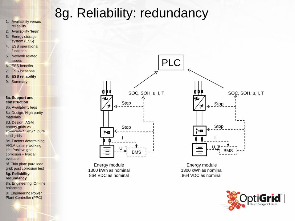
8g. Reliability: redundancy
BMSU, T
I
Stop
Stop
SOC, SOH, u, I, T
BMSU, T
I
Stop
Stop
SOC, SOH, u, I, T
PLC
Energy module1300 kWh as nominal
864 VDC as nominal
Energy module1300 kWh as nominal
864 VDC as nominal
1. Availability versus
reliability
2. Availability “legs”
3. Energy storage
system (ESS)
4. ESS operational
functions
5. Network related
issues
6. ESS benefits
7. ESS locations
8. ESS reliability
9. Summary
8a. Support and
construction
8b. Availability legs
8c. Design: High purity
materials
8d. Design: AGM
battery grids vs
PowerSafe ® SBS ® pure
lead grids
8e. Factors determining
VRLA battery working
life: Positive grid
corrosion – typical
evolution
8f. Thin plate pure lead
grid: post corrosion test
8g. Reliability:
redundancy
8h. Engineering: On-line
balancing
8i. Engineering Power
Plant Controller (PPC)
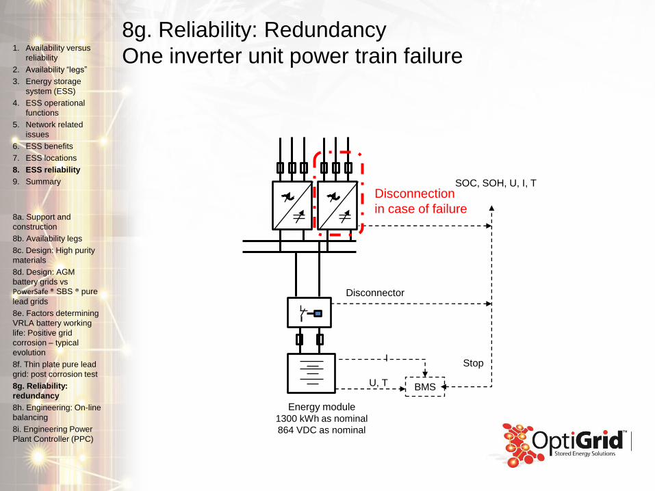
8g. Reliability: Redundancy
One inverter unit power train failure
Energy module1300 kWh as nominal
864 VDC as nominal
Disconnector
BMSU, T
IStop
SOC, SOH, U, I, TDisconnection
in case of failure
1. Availability versus
reliability
2. Availability “legs”
3. Energy storage
system (ESS)
4. ESS operational
functions
5. Network related
issues
6. ESS benefits
7. ESS locations
8. ESS reliability
9. Summary
8a. Support and
construction
8b. Availability legs
8c. Design: High purity
materials
8d. Design: AGM
battery grids vs
PowerSafe ® SBS ® pure
lead grids
8e. Factors determining
VRLA battery working
life: Positive grid
corrosion – typical
evolution
8f. Thin plate pure lead
grid: post corrosion test
8g. Reliability:
redundancy
8h. Engineering: On-line
balancing
8i. Engineering Power
Plant Controller (PPC)
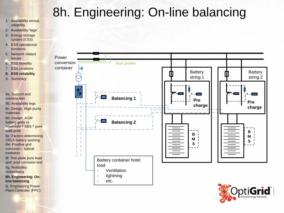
8h. Engineering: On-line balancing
Balancing 1
Balancing 2
Battery container hotel
load
- Ventilation
- lightning
- etc.
B
M
S
Pre
chargePre
charge
Battery
string 1
Battery
string 2
Aux power
Power
conversion
container
B
M
S
1. Availability versus
reliability
2. Availability “legs”
3. Energy storage
system (ESS)
4. ESS operational
functions
5. Network related
issues
6. ESS benefits
7. ESS locations
8. ESS reliability
9. Summary
8a. Support and
construction
8b. Availability legs
8c. Design: High purity
materials
8d. Design: AGM
battery grids vs
PowerSafe ® SBS ® pure
lead grids
8e. Factors determining
VRLA battery working
life: Positive grid
corrosion – typical
evolution
8f. Thin plate pure lead
grid: post corrosion test
8g. Reliability:
redundancy
8h. Engineering: On-
line balancing
8i. Engineering Power
Plant Controller (PPC)

8i. Engineering Power Plant Controller (PPC)
Power plant control:• Each power conversion container has
own controller that controls ESS
• Power plant has own controller that
communicates with customer
Control system (SCADA or similar)• PPC sets new parameters or control
modes of system after receiving them
from customer control system
• PPC communicates status information
of power plant (SOC, operating ESS,
etc.)
• PPC asks permission for balancing of
energy string
1. Availability versus
reliability
2. Availability “legs”
3. Energy storage
system (ESS)
4. ESS operational
functions
5. Network related
issues
6. ESS benefits
7. ESS locations
8. ESS reliability
9. Summary
8a. Support and
construction
8b. Availability legs
8c. Design: High purity
materials
8d. Design: AGM
battery grids vs
PowerSafe ® SBS ® pure
lead grids
8e. Factors determining
VRLA battery working
life: Positive grid
corrosion – typical
evolution
8f. Thin plate pure lead
grid: post corrosion test
8g. Reliability:
redundancy
8h. Engineering: On-line
balancing
8i. Engineering Power
Plant Controller (PPC)
9. EnerSys® OptiGrid TM summary
• OptiGrid TM Stored Energy Solutions is modular battery based
Energy Storage System and can it be installed any place in grid
• OptiGrid TM has several functions that can support network
• As battery based ESS, OptiGrid TM can react rapidly to the demand
from network
• Benefits for the grid
• Can help to increase availability
• Minimizes network disturbance effects
• Support network availability at customer site
• Allows to optimize the usage of energy
1. Availability versus
reliability
2. Availability “legs”
3. Energy storage
system (ESS)
4. ESS operational
functions
5. Network related
issues
6. ESS benefits
7. ESS locations
8. ESS reliability
9. Summary
EnerSys World Headquarters 2366 Bernville Road, Reading, PA
19605, USA Tel: +1-610-208-1991 / +1-800-538-3627
EnerSys EMEA EH Europe GmbH, Löwenstrasse 32, 8001 Zurich,
Switzerland
EnerSys Asia 152 Beach Road, Gateway East Building Level 11,
189721 Singapore Tel: +65 6508 1780
© 2014 EnerSys. All rights reserved.Trademarks and logos are the
property of EnerSys and its affiliates unless otherwise noted. Subject to
revisions without prior notice. E.&O.E.
www.optigrid.enersys.com
Publication number: WEBINAR -001-FEB 2014