Embed Size (px)
Citation preview
7/24/2019 Optimized Implementation of Edge Preserving Color Guided Filter for Video on FPGA
http://slidepdf.com/reader/full/optimized-implementation-of-edge-preserving-color-guided-filter-for-video-on 1/7
IOSR Journal of VLSI and Signal Processing (IOSR-JVSP)Volume 5, Issue 6, Ver. I (Nov -Dec. 2015), PP 27-33e-ISSN: 2319 – 4200, p-ISSN No. : 2319 – 4197www.iosrjournals.org
DOI: 10.9790/4200-05612733 www.iosrjournals.org 27 | Page
Optimized Implementation of Edge Preserving Color Guided
Filter for Video on FPGA Anita Anandrao Salunkhe1, Uttam Laxman Bombale2
1(PG Scholar (Electronic Engg.), Department of Technology, Shivaji University, Kolhapur, Maharashtra, India)
2(Assoc. prof. (Electronic Engg), Department of Technology, Shivaji University, Kolhapur, Maharashtra, India)
Abstract: Filtering is widely used in image and video processing for various applications like noise reduction,
feature extraction, smoothing, detail enhancement etc. Bilateral filter is a most popular filtering method but it
produces gradient reversal artifacts near edges. To overcome this drawback, guided filter is used for various
applications. To develop real time detail enhancement application, hardware implementation of guided filter is
proposed by using system generator tool. In this paper, guided filter is implemented on FPGA for video withoptimized frame rate of 284 fps to make time efficient system and also resources are optimized to make area
efficient system. This hardware based design of guided filter using color guidance image is applied for real timevideo in detail enhancement application.
Keywords - Guided filter, detail enhancement, FPGA, resource optimization, system generator.
I. IntroductionImage filtering is a technique in image and video processing which is used to reduce noise and extract
important features. Applications which are based on image filtering are smoothing, detail enhancement, texture
editing, colorization, haze removal, feathering, etc. Image filtering is classified into two groups: transform
domain and spatial domain. In transform domain filtering, image transform is taken and then operations are
performed. And finally, inverse transform is carried out to get output in spatial domain. Spatial domain filtering
has two types: intensity transformation and spatial filtering. In intensity transformation, operation is performed
on one pixel only. And in case of spatial filtering, value of pixel is computed by performing operation onneighborhood pixels. Spatial filtering is subdivided into two types: linear and non-linear spatial filtering. If
operation performed on pixels is linear then it is said to be linear filtering and if operation performed on pixels is
non-linear then it is called non-linear filtering.
In particular, edge preserving filtering is very much important in variety of applications like
sharpening, blurring, edge detection and detail enhancement. For this purpose, different edge preserving filtering
techniques has been developed such as sparse norm filtering [1], anisotropic diffusion [2], weighted least square
[3], bilateral filter [4], etc. Sparse norm filtering and anisotropic diffusion are time consuming methods.
Weighted least square reduces ringing effect near edges but many parameters from blurred data are required.
Among these techniques, bilateral filter is a most popular, simple and non-iterative filter which is used in variety
of applications like HDR compression [5], noise reduction [6], detail decomposition [7], etc. Flash / no-flash
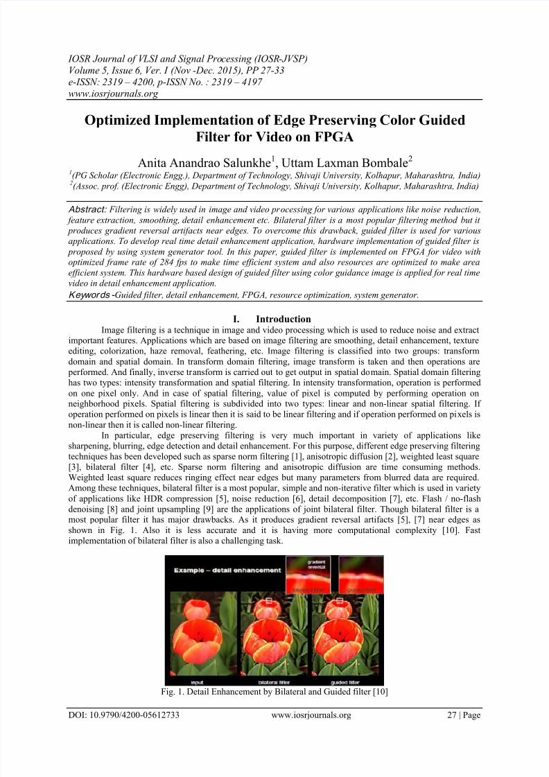
denoising [8] and joint upsampling [9] are the applications of joint bilateral filter. Though bilateral filter is amost popular filter it has major drawbacks. As it produces gradient reversal artifacts [5], [7] near edges as
shown in Fig. 1. Also it is less accurate and it is having more computational complexity [10]. Fast
implementation of bilateral filter is also a challenging task.
Fig. 1. Detail Enhancement by Bilateral and Guided filter [10]
7/24/2019 Optimized Implementation of Edge Preserving Color Guided Filter for Video on FPGA
http://slidepdf.com/reader/full/optimized-implementation-of-edge-preserving-color-guided-filter-for-video-on 2/7
Optimized Implementation of Edge Preserving Color Guided Filter for Video on FPGA
DOI: 10.9790/4200-05612733 www.iosrjournals.org 28 | Page
To overcome the drawbacks of bilateral filter, guided filter [10] is developed which has same edge
preserving property like bilateral filter. Output produced by guided filter is free from gradient reversal artifacts
as shown in Fig. 1. Its behavior near edges is good as compared to bilateral filter. It is a non-approximate, fast,
linear type of filter which can be used in variety of real time applications. Importance filtering [11] utilizes
guided filter to filter out image saliency. Guided filter is applied at post processing step in alpha matting [12].
Guided filter is used for fast cost volume filtering to improve the quality which is degraded by bilateral filter[13]. Chia et al. [14] used guided filter for semantic colorization with the help of images from internet. In [15],
guided filter is used in single image multi-focusing which is based on local blur estimation. Zhang et al. [16]
used guided filter to remove haze from video with spatial and temporal coherence. Hosni et al. [17] applied
guided filter for computing temporally consistent disparity maps from video.With increase in image sizes, software for image processing has become less useful as PC processors
are made for general purpose. In order to deal with large image sizes and high speed, hardware devices are
needed. Parallel processing hardware is essential in image processing to perform large number of operations and
high speed data transfer. FPGA is having the capability of parallel processing and hence it is a good platform for
image processing [18]. So, here we are using FPGA for implementation of guided filter. In [19], guided filter for
video is implemented with frame rate of 30 fps. Here, frame rate is optimized to make time efficient system.
And also resources are optimized to make area efficient system. Performance of guided filter using color
guidance image is better as compared to grayscale guidance image [10]. Hence, we are implementing color
guided filter for video for real time detail enhancement application with the help of Xilinx system generator.The paper is organized as follows. The guided filter and its algorithm are described in Section II.
Hardware implementation of guided filter for detail enhancement application is discussed in Section III. The
results are analyzed in Section IV. Section V concludes the paper.
II. Guided filterGuided filter produces filtered output ‘q’ by using guidance image ‘ I ’ and input image ‘ p’. Based on
the application, guidance image can be input image itself or different image.
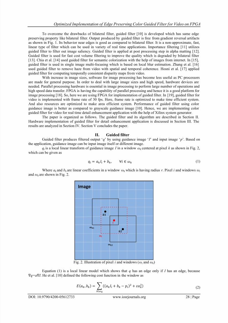
qi is a local linear transform of guidance image I in a window ωk centered at pixel k as shown in Fig. 2,
which can be given as
= + , ∀ ∈ (1)
Where ak and bk are linear coefficients in a window ωk which is having radius r . Pixel i and windows ωi and ωk are shown in Fig. 2.
Fig. 2. Illustration of pixel i and windows (ωi and ωk )
Equation (1) is a local linear model which shows that q has an edge only if I has an edge, because
∇q=a∇ I . He et al. [10] defined the following cost function in the window as
( , ) = (( + − )2 + 2)∈
(2)
7/24/2019 Optimized Implementation of Edge Preserving Color Guided Filter for Video on FPGA
http://slidepdf.com/reader/full/optimized-implementation-of-edge-preserving-color-guided-filter-for-video-on 3/7
Optimized Implementation of Edge Preserving Color Guided Filter for Video on FPGA
DOI: 10.9790/4200-05612733 www.iosrjournals.org 29 | Page
Here ε is a regularization parameter which prevents ak from being too large. Solution of linear
coefficients ak and bk for above cost function is given as
=
|| ∑ − ∈
2
+ (3)
= − (4)
Here μk and 2are mean and variance of I in ωk . |ω| is number of pixels in ωk . is the mean of p in ωk
which is given as
= 1||
∈ (5)
For pixel i in the image, the value of qi is different for different windows as shown in Fig. 2. So simple
strategy is to average the values of qi. So after computing linear coefficients for all windows ωk in the image, the
filtered output is given as
= 1|| ( + ):∈
(6)
= + (7)
Now, edge preserving filtering for guided filter is explained. Consider the case I = p. If ε = 0 then
solution to equation (2) is ak = 1 and bk = 0. If ε>0, two cases are formed:
Case 1: “flat patch.” if the image I is constant in ωk then we get ak = 0 and bk = .
Case 2: “high variance.” if the image I changes a lot in ωk then we get ak = 1 and bk = 0.
ak , bk are averaged to get and and then filtered output is computed by using equation (7). If a pixel is in
middle of a “flat patch” area then its value becomes the average of neighborhood pixels and if a pixel is inmiddle of a “high variance” area then its value is unchanged. This shows an edge preserving property of guided
filter.
1.1 Guided filter algorithm
1. Read the image say I (color image) which acts as the guidance image.
2. Take p=I , where p is filtering image (color image).
3. Take the values for r and ε where r is radius of window and ε is regularization parameter.
4. Compute following mean values by applying averaging filter ‘ f mean’:
mean I = f mean( I )
mean p = f mean( p)
mean Ip = f mean( I .* p)mean II = f mean( I .* I )
5. Compute covariance of ( I,p) using formula:
cov Ip = mean Ip – mean I .* mean p
6. Compute variance using formula:
var I = mean II – mean I .* mean I
7. Compute linear coefficients a and b as:a = cov Ip/ (var I + ε )
b = mean p – a .* mean I
8. Compute mean of a and b as:
meana = f mean(a)
meanb = f mean(b)
9. Compute filtered output as:q = meana .* I + meanb
III. Hardware implementationSystem generator is a digital signal processing (DSP) design tool from Xilinx which uses model based
Simulink design environment for designing the FPGAs. It provides Xilinx specific blockset to capture the
design in Simulink modelling environment. While implementing system generator blocks, Xilinx Integrated
Software Environment (ISE) is working in background. System generator automatically invokes Xilinx core
7/24/2019 Optimized Implementation of Edge Preserving Color Guided Filter for Video on FPGA
http://slidepdf.com/reader/full/optimized-implementation-of-edge-preserving-color-guided-filter-for-video-on 4/7
Optimized Implementation of Edge Preserving Color Guided Filter for Video on FPGA
DOI: 10.9790/4200-05612733 www.iosrjournals.org 30 | Page
generator to generate highly optimized netlists for the DSP building blocks. System generator performs all
downstream FPGA implementation steps such as synthesis, place and route automatically to generate
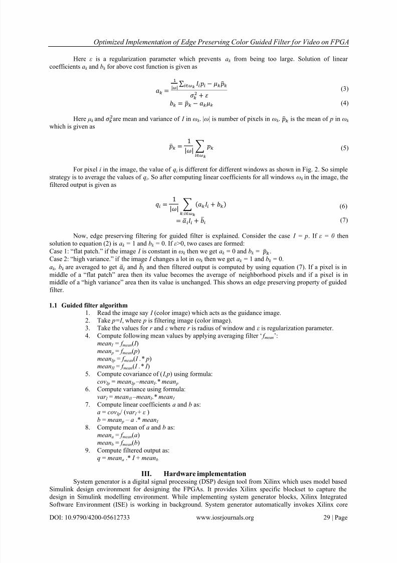
programming file for FPGA. Hardware implementation using system generator is shown in Fig. 3, which is time
efficient as compared to conventional HDL coding. The virtex-6 xc6vlx240t-1ff1156 FPGA device is employed
here and software used are Xilinx 14.2 and MATLAB 2012a. System generator has the ability to run a hardware
co-simulation.
Fig. 3. Hardware implementation using Xilinx system generator
Based on the guided filter algorithm which is explained in section III, guided filter is designed using
system generator tool. This design is compiled and downloaded to virtex-6 xc6vlx240t-1ff1156 FPGA devicefor hardware co-simulation. Video generated by Simulink is sent to FPGA, processed and then returned to
DSP System Simulation
Implementation
Hardware
in the loop
Hardware
Verification
&Acceleration
Simulink Model Code Generation
System Generator
MATLAB Environment
RTL HDL & IP Core
Xilinx
Implementation
Flow
Bitstream
7/24/2019 Optimized Implementation of Edge Preserving Color Guided Filter for Video on FPGA
http://slidepdf.com/reader/full/optimized-implementation-of-edge-preserving-color-guided-filter-for-video-on 5/7
Optimized Implementation of Edge Preserving Color Guided Filter for Video on FPGA
DOI: 10.9790/4200-05612733 www.iosrjournals.org 31 | Page
Simulink to display it. In this way, design can be tested with hardware in the loop by taking input and output
from MATLAB. This process is called as hardware co-simulation.
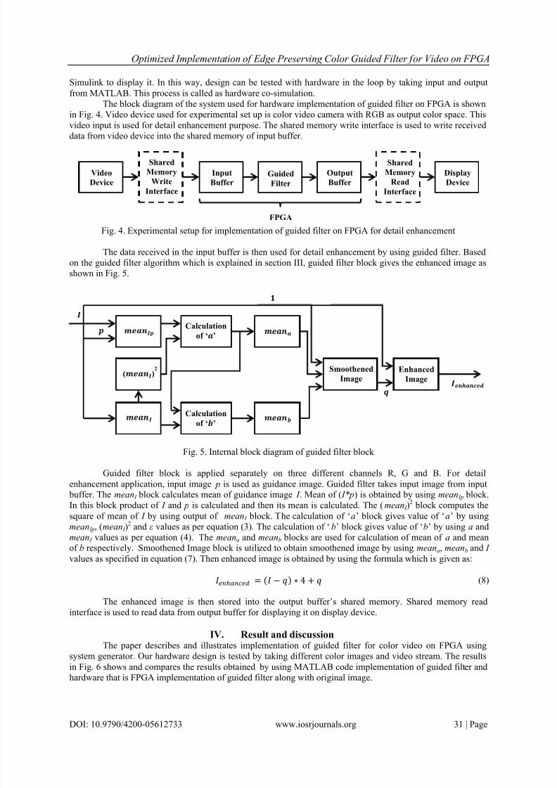
The block diagram of the system used for hardware implementation of guided filter on FPGA is shown
in Fig. 4. Video device used for experimental set up is color video camera with RGB as output color space. This
video input is used for detail enhancement purpose. The shared memory write interface is used to write received
data from video device into the shared memory of input buffer.
Fig. 4. Experimental setup for implementation of guided filter on FPGA for detail enhancement
The data received in the input buffer is then used for detail enhancement by using guided filter. Based
on the guided filter algorithm which is explained in section III, guided filter block gives the enhanced image as
shown in Fig. 5.
Fig. 5. Internal block diagram of guided filter block
Guided filter block is applied separately on three different channels R, G and B. For detail
enhancement application, input image p is used as guidance image. Guided filter takes input image from input buffer. The mean I block calculates mean of guidance image I . Mean of ( I*p) is obtained by using mean Ip block.
In this block product of I and p is calculated and then its mean is calculated. The (mean I )2 block computes the
square of mean of I by using output of mean I block. The calculation of ‘a’ block gives value of ‘a’ by using
mean Ip, (mean I )2 and ε values as per equation (3). The calculation of ‘b’ block gives value of ‘b’ by using a and
mean I values as per equation (4). The meana and meanb blocks are used for calculation of mean of a and mean
of b respectively. Smoothened Image block is utilized to obtain smoothened image by using meana, meanb and I values as specified in equation (7). Then enhanced image is obtained by using the formula which is given as:
ℎ = ( − ) ∗ 4 + (8)
The enhanced image is then stored into the output buffer’s shared memory. Shared memory read
interface is used to read data from output buffer for displaying it on display device.
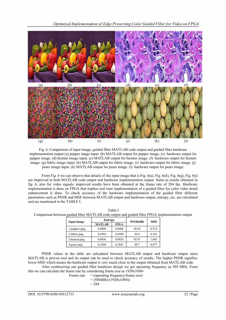
IV. Result and discussionThe paper describes and illustrates implementation of guided filter for color video on FPGA using
system generator. Our hardware design is tested by taking different color images and video stream. The results
in Fig. 6 shows and compares the results obtained by using MATLAB code implementation of guided filter and
hardware that is FPGA implementation of guided filter along with original image.
()2
Calculation
of ‘’
Calculationof ‘’
Smoothened
Image Enhanced
Image
Video
Device
Shared
Memory Write
Interface
Input
Buffer Guided
Filter Output
Buffer
Shared
Memory
Read
Interface
Display
Device
FPGA
7/24/2019 Optimized Implementation of Edge Preserving Color Guided Filter for Video on FPGA
http://slidepdf.com/reader/full/optimized-implementation-of-edge-preserving-color-guided-filter-for-video-on 6/7
Optimized Implementation of Edge Preserving Color Guided Filter for Video on FPGA
DOI: 10.9790/4200-05612733 www.iosrjournals.org 32 | Page
(a) (b) (c) (d) (e) (f)
(g) (h) (i) (j) (k) (l)
Fig. 6. Comparison of input image, guided filter MATLAB code output and guided filter hardwareimplementation output (a) pepper image input. (b) MATLAB output for pepper image. (c) hardware output for
pepper image. (d) hestain image input. (e) MATLAB output for hestain image. (f) hardware output for hestain
image. (g) fabric image input. (h) MATLAB output for fabric image. (i) hardware output for fabric image. (j)
pears image input. (k) MATLAB output for pears image. (l) hardware output for pears image.
From Fig. 6 we can observe that details of the input image that is Fig. 6(a), Fig. 6(d), Fig. 6(g), Fig. 6(j)are improved in both MATLAB code output and hardware implementation output. Same as results obtained in
fig. 6, also for video signals, improved results have been obtained at the frame rate of 284 fps. Hardware
implementation is done on FPGA that implies real time implementation of a guided filter for color video detail
enhancement is done. To check accuracy of the hardware implementation of the guided filter different
parameters such as PSNR and MSE between MATLAB output and hardware output, entropy, etc. are calculatedand are mentioned in the TABLE I.
Table I
Comparison between guided filter MATLAB code output and guided filter FPGA implementation output
PSNR values in the table are calculated between MATLAB output and hardware output since
MATLAB is proven tool and its output can be used to check accuracy of results. The higher PSNR signifies
lower MSE which means the hardware output is very much close to the output obtained from MATLAB code.
After synthesizing our guided filter hardware design we get operating frequency as 589 MHz. From
this we can calculate the frame rate by considering frame size as 1920x1080-
Frame rate = (operating frequency/frame size)
= (586MHz/(1920x1080))= 284
Input imageEntropy
PSNR(dB) MSE
MATLAB FPGA1.peppers.png 0.4009 0.4008 50.54 0.574
2.fabric.png 0.6992 0.6989 50.8 0.541
3.hestain.png 0.0930 0.0929 45.97 1.645
4.pears.png 0.1844 0.1843 48.7 0.877
7/24/2019 Optimized Implementation of Edge Preserving Color Guided Filter for Video on FPGA
http://slidepdf.com/reader/full/optimized-implementation-of-edge-preserving-color-guided-filter-for-video-on 7/7
Optimized Implementation of Edge Preserving Color Guided Filter for Video on FPGA
DOI: 10.9790/4200-05612733 www.iosrjournals.org 33 | Page
The proposed hardware design of guided filter for video is time efficient as it provides high frame rate
of 284 fps.
Virtex-6 xc6vlx240t-1ff1156 FPGA device is used for the hardware implementation of guided filter for
detail enhancement application. Resources utilized are summarized in the TABLE II which shows that our
guided filter implementation requires minimum number of resources which yields area efficient system.
Table II
Resource utilization summaryLogic utilization Used Available Utilization
Number of Slice Registers 10463 301440 3%
Number of Slice LUTs 1619 150720 1%
Number of fully used LUT-FF pairs 1198 10884 11%
V. ConclusionIn this paper, hardware implementation of guided filter for video is proposed. The obtained hardware
outputs are pretty close to the MATLAB output. High frame rate i.e. 284 fps is achieved by the proposed
hardware design of guided filter, so it is well suited for video processing applications. Also this hardware design
is area efficient as its FPGA implementation requires minimum number of resources. Here, it gives better output
for detail enhancement application. Proposed guided filter FPGA design may perform well in many video processing applications.
References[1] C. Ye, D. Tao, M. Song, D. Jacobs, and M. Wu, Sparse Norm Filtering, arXiv preprint, arXiv: 1305.3971, 2013.
[2] P. Perona and J. Malik, Scale-space and edge detection using anisotropic diffusion, IEEE Trans. PAMI, 12(7), 1990, 629 – 639.
[3] R. L. Lagendijk, J. Biemond, and D. E. Boekee, Regularized iterative image restoration with ringing reduction, IEEE Trans.Acoust., Speech, Signal Processing, 36(12), 1988, 1874 – 1888.
[4] C. Tomasi and R. Manduchi, Bilateral filtering for gray and color images, Proc. IEEE 6th ICCV, Mumbai, India, 1998, 839 – 846.
[5] F. Durand and J. Dorsey, Fast bilateral filtering for the display of high-dynamic-range images, ACM Trans. Graph., 21(3), 2002, 257 – 266.
[6] C. Liu, W. Freeman, R. Szeliski, and S. B. Kang, Noise estimation from a single image, Proc. IEEE CVPR, New York City, NY,
2006, 901 – 908.[7] Z. Farbman, R. Fattal, D. Lischinski, and R. Szeliski, Edge-preserving decompositions for multiscale tone and detail manipulation,
ACM Trans. Graph., 27(3), 2008, 67:1 – 67:10.
[8]
G. Petschnigg, R. Szeliski, M. Agrawala, M. Cohen, H. Hoppe, and K. Toyama, Digital photography with flash and no-flash image pairs, ACM Trans. Graph., 23(3), 2004, 664 – 672.
[9] J. Kopf, M. F. Cohen, D. Lischinski, and M. Uyttendaele, Joint bilateral upsampling, ACM Trans. Graph., 26(3), 2007.
[10] K. He, J. Sun, and X. Tang, Guided image filtering, Proc. 11th ECCV: PartI, Heraklion, Greece, 2010, 1 – 14.[11] Y. Ding, J. Xiao, and J. Yu, Importance filtering for image retargeting, Proc. IEEE Conf. CVPR, Colorado Springs, CO, 2011, 89 –
96.
[12] K. He, C. Rhemann, C. Rother, X. Tang, and J. Sun, A global sampling method for alpha matting, Proc. IEEE Conf. CVPR,Colorado Springs, CO ,2011, 2049 – 2056.
[13] C. Rhemann, A. Hosni, M. Bleyer, C. Rother, and M. Gelautz, Fast cost-volume filtering for visual correspondence and beyond,
Proc. IEEE Conf. CVPR, Colorado Springs, CO, 2011, 3017 – 3024.
[14] A. Y. -S. Chia, S. Zhuo, R. K. Gupta, Y. -W. Tai, S. -Y. Cho, P. Tan, and S. Lin, Semantic colorization with internet images, ACM
Trans. Graph., 30(6), 2011, 156:1 – 156:8.
[15] Y. Cao, S. Fang, and F. Wang, Single image multi-focusing based on local blur estimation, Proc.6th ICIG, Hefei, Anhui, China,2011, 168 – 175.
[16] J. Zhang, L. Li, Y. Zhang, G. Yang, X. Cao, and J. Sun, Video dehazing with spatial and temporal coherence, Vis. Comput., 27,
2011, 749 – 757.
[17]
A. Hosni, C. Rhemann, M. Bleyer, and M. Gelautz, Temporally consistent disparity and optical flow via efficient spatio-temporalfiltering, Advances in Image and Video Technology, Gwangju, South Korea, 2011, 165 – 177.
[18] B. Dimitrios, T. Vassilis, F. Nikolaos, and T. Christos, An FPGA-based hardware implementation of configurable pixel-level color
image fusion, IEEE Trans. Geosci. Remote Sens., 50(2), 2012, 362 – 373.
[19] C. -C. Kao, J. -H. Lai, and S. -Y. Chien, VLSI Architecture Design of Guided Filter for 30 Frames/s Full-HD Video, IEEE Trans.on Cir. and Sys. for Video Tech., 24( 3), 2014, 513-524.


![A-Port Networks: Preserving the Timed Behavior of Synchronous … · 2016-02-17 · whichaimstocreateavariant oftheIntelAsim simulationenvironment[Emer 84 et al. 2002] on an FPGA](https://img.pdfslide.net/doc/110x75/5f803ba2f2fee901e141e15f/a-port-networks-preserving-the-timed-behavior-of-synchronous-2016-02-17-whichaimstocreateavariant.jpg)