Embed Size (px)
Citation preview

Optimizing Custom Magnetics forHigh-Performance Power Supplies
Michael Seeman, Ph.D.Founder / CEO — Eta One Power, Inc.
© 2018 Eta One Power, Inc.April 2018 PELS Seminar

Eta One Power, Inc
Outline
• What is Power Supply Optimization?– Performance metrics, optimization tools and co-design methodologies
• System requirements placed on magnetic structures
• Inductor and transformer loss mechanisms– DC winding loss
– Core loss
– AC winding loss: skin depth, proximity effect & fringe-field losses
– Winding capacitances
• Examining magnetics scaling
• Software tools for whole-converter analysis & optimization
• Case studies
• Conclusions
© 2018 Eta One Power, Inc. 2

Eta One Power, Inc
Power Converter Figures of Merit
Cost, cost, costPower DensityReliabilityTime to MarketSupply ChainPassing EMC, UL…EfficiencyTransient Response
Manufacturing
Specifications
Technology
© 2018 Eta One Power, Inc.
Eta One Power, Inc
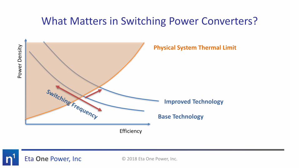
What Matters in Switching Power Converters?
Efficiency
Pow
er D
ensi
ty Physical System Thermal Limit
Base Technology
Improved Technology
© 2018 Eta One Power, Inc.

Eta One Power, Inc
How is Design Optimization Done Today?
Pricing/SupplyDigikey
Octopart
OptimizationMATLAB,
Custom Excel Spreadsheet
Loss ModelsPower Electronics
Textbooks
Sim/ControlPSIM, SIMPLIS, PLECS, LTSpice
© 2018 Eta One Power, Inc.

Eta One Power, Inc
The Eta Designer AdvantageEta Designer provides instant, simultaneous design and simulation of power systems
Flexible Schematic Editor
• Create arbitrary topologies• Parameterize and sweep anything• Automatically create standard designs
Fast Simulation Engine
• Ultra-fast linear simulation engine• Instant results – runs in the background• Control stability and loop response
Powerful Controller Design
• Flexible, intuitive specification• PWM and variable-frequency designs• Arbitrarily control each rising/falling edge
Magnetics Optimization
• Custom designed magnetics integrated with simulation
• Supports Litz & planar designs• Complex, high-frequency loss analysis
Efficiency Modeling
• Real-time efficiency estimation based on simulated operating conditions
• Modern peer-reviewed loss models• Free real-time parameter variation
Component Database
• Vast database of component data• Chooses top-10 devices, shows power loss
for each one
© 2018 Eta One Power, Inc.
Eta One Power, Inc
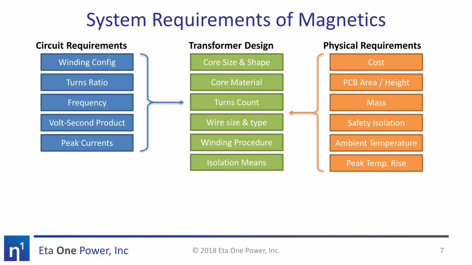
System Requirements of Magnetics
© 2018 Eta One Power, Inc. 7
Circuit Requirements
Winding Config
Turns Ratio
Frequency
Volt-Second Product
Peak Currents
Physical Requirements
Mass
Safety Isolation
Cost
PCB Area / Height
Ambient Temperature
Peak Temp. Rise
Transformer Design
Turns Count
Wire size & type
Core Size & Shape
Core Material
Winding Procedure
Isolation Means

Eta One Power, Inc
Magnetics Loss Mechanisms
© 2018 Eta One Power, Inc. 8
DC Resistance Loss Core Loss
AC Winding Losses Winding Capacitance Losses
• Incorporates I2R copper losses based on RMS currents
• Minimizing DC loss involves choosing a large winding window & short turn length, and maximizing copper fill factor
• Captures core hysteresis and eddy current losses• Steinmetz equation:
• Non-linear effects with waveform shape, core geometry, and DC bias
• Capacitances between winding turns yields additional switching losses in circuit
• EMC concerns from charge injection from primary to secondary
• Winding construction and shielding layers can mitigate these effects
• Additional winding loss due to high-frequency skin effect, external H-fields due to other windings (proximity) and core gap (fringing)
• Frequency-dependent; linear with winding currents
𝑃𝑣 = 𝑘𝑓𝛼 𝐵𝛽
Eta One Power, Inc
Magnetics Loss: DC Resistance
© 2018 Eta One Power, Inc. 9
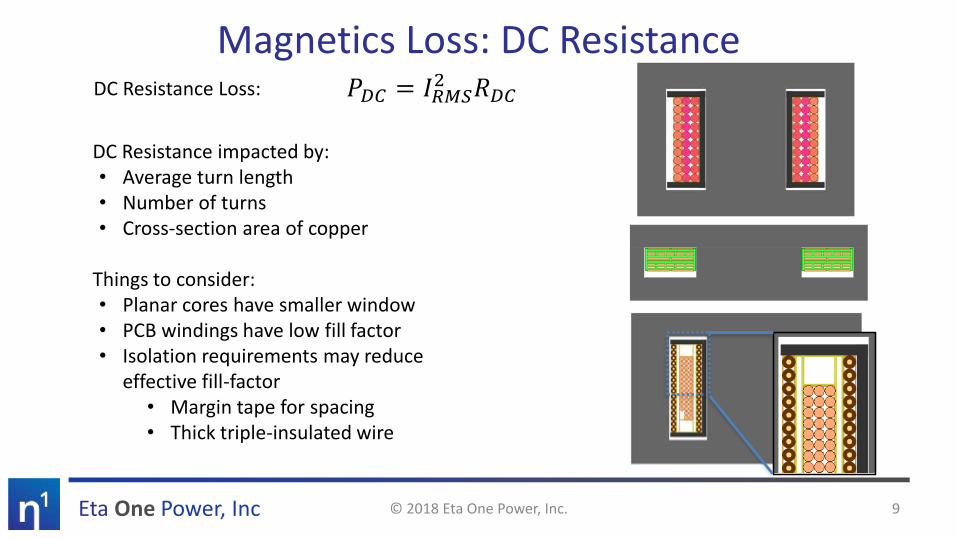
DC Resistance Loss: 𝑃𝐷𝐶 = 𝐼𝑅𝑀𝑆2 𝑅𝐷𝐶
DC Resistance impacted by:• Average turn length• Number of turns• Cross-section area of copper
Things to consider:• Planar cores have smaller window• PCB windings have low fill factor• Isolation requirements may reduce
effective fill-factor• Margin tape for spacing• Thick triple-insulated wire

Eta One Power, Inc
Magnetics Loss: Core Loss
© 2018 Eta One Power, Inc. 10
Ferroxcube Data Handbook
Core Loss incorporates hysteretic and eddy-current losses and is a function of Flux Density Amplitude and Frequency
Steinmetz Equation:
𝑃𝑣 = 𝑘𝑓𝛼 𝐵𝛽 [kW/m3]
flux density found using either:
𝐵 =𝑉∆𝑡
2𝑛𝐴𝑒applied volt-seconds
𝐵 =𝐿 መ𝐼
𝑛𝐴𝑒inductance & current ripple
Note: k, α and ß vary with frequency; refer to plots

Eta One Power, Inc
Core Loss vs. Frequency
Ferroxcube data handbook
Log-Linear Plot• Core Loss does get better at higher frequency
• Inductors with “small” ripple get better
• “Large” ripple inductors are a mixed bag:
• Core loss improves
• Skin & proximity effect is worse
• Transformers are impacted more from skin and proximity loss; gains are modest
9x
3x
1.7x
© 2018 Eta One Power, Inc. 11
Eta One Power, Inc
Core Loss: Non-sinusoidal Waveforms
© 2018 Eta One Power, Inc. 12
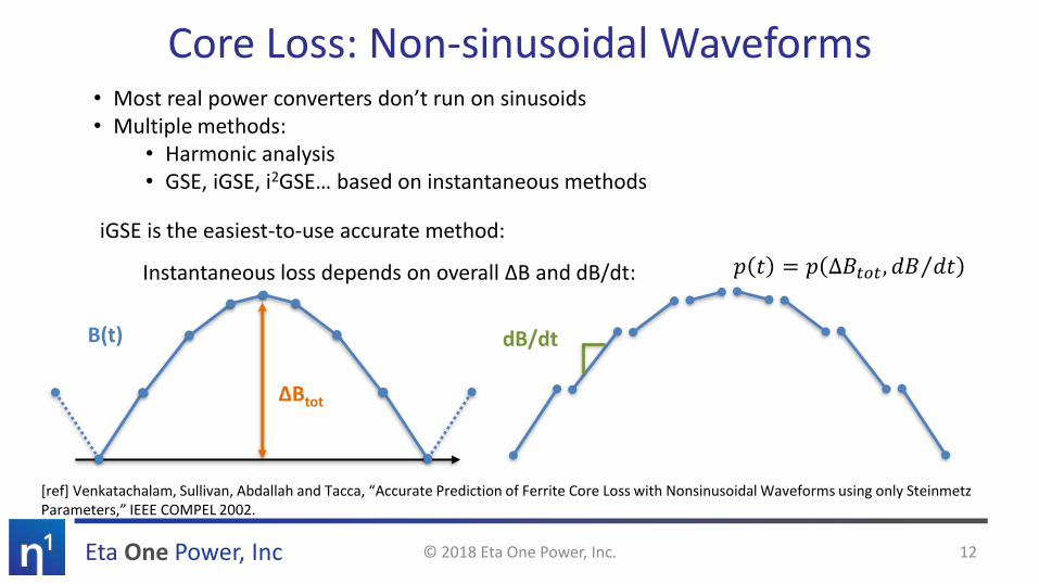
• Most real power converters don’t run on sinusoids• Multiple methods:
• Harmonic analysis• GSE, iGSE, i2GSE… based on instantaneous methods
iGSE is the easiest-to-use accurate method:
Instantaneous loss depends on overall ∆B and dB/dt: 𝑝 𝑡 = 𝑝 ∆𝐵𝑡𝑜𝑡 , Τ𝑑𝐵 𝑑𝑡
B(t)
∆Btot
dB/dt
[ref] Venkatachalam, Sullivan, Abdallah and Tacca, “Accurate Prediction of Ferrite Core Loss with Nonsinusoidal Waveforms using only Steinmetz Parameters,” IEEE COMPEL 2002.

Eta One Power, Inc
Magnetics Loss: AC Winding Losses
© 2018 Eta One Power, Inc. 13
Additionalcopper losses
Eddy currents induced to cancel H field
Current in single wire or turn
H-field generated by nearby turns and windings
Fringing H-field contributed by core gap(s)
Skin
De
pth
Pro
xim
ity
Frin
gin
g

Eta One Power, Inc
AC Winding Losses: Skin Depth
© 2018 Eta One Power, Inc. 14
At high frequencies, eddy currents generated by the magnetic field drive the internal current to zero
Skin Depth: 𝛿 =1
𝜋𝜎𝜇𝑓
Litz wire or foil can be used to counter skin effect
[Wikipedia]
Eta One Power, Inc
AC Winding Losses: Proximity Effect
© 2018 Eta One Power, Inc. 15
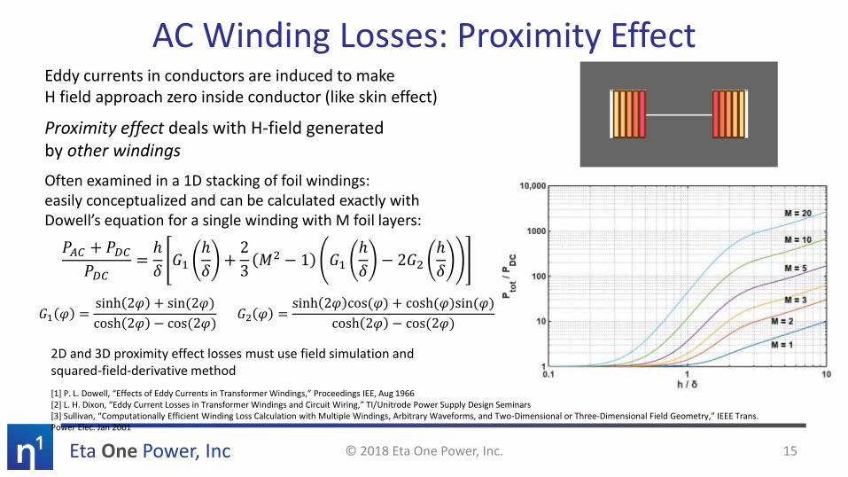
Eddy currents in conductors are induced to makeH field approach zero inside conductor (like skin effect)
Proximity effect deals with H-field generatedby other windings
Often examined in a 1D stacking of foil windings:easily conceptualized and can be calculated exactly withDowell’s equation for a single winding with M foil layers:
[1] P. L. Dowell, “Effects of Eddy Currents in Transformer Windings,” Proceedings IEE, Aug 1966[2] L. H. Dixon, “Eddy Current Losses in Transformer Windings and Circuit Wiring,” TI/Unitrode Power Supply Design Seminars[3] Sullivan, “Computationally Efficient Winding Loss Calculation with Multiple Windings, Arbitrary Waveforms, and Two-Dimensional or Three-Dimensional Field Geometry,” IEEE Trans. Power Elec. Jan 2001
2D and 3D proximity effect losses must use field simulation and squared-field-derivative method
𝑃𝐴𝐶 + 𝑃𝐷𝐶𝑃𝐷𝐶
=ℎ
𝛿𝐺1
ℎ
𝛿+2
3𝑀2 − 1 𝐺1
ℎ
𝛿− 2𝐺2
ℎ
𝛿
𝐺1 𝜑 =sinh 2𝜑 + sin(2𝜑)
cosh 2𝜑 − cos(2𝜑)𝐺2 𝜑 =
sinh 2𝜑 cos(𝜑) + cosh(𝜑)sin(𝜑)
cosh 2𝜑 − cos(2𝜑)
Eta One Power, Inc
Proximity Effect Example
© 2018 Eta One Power, Inc. 16
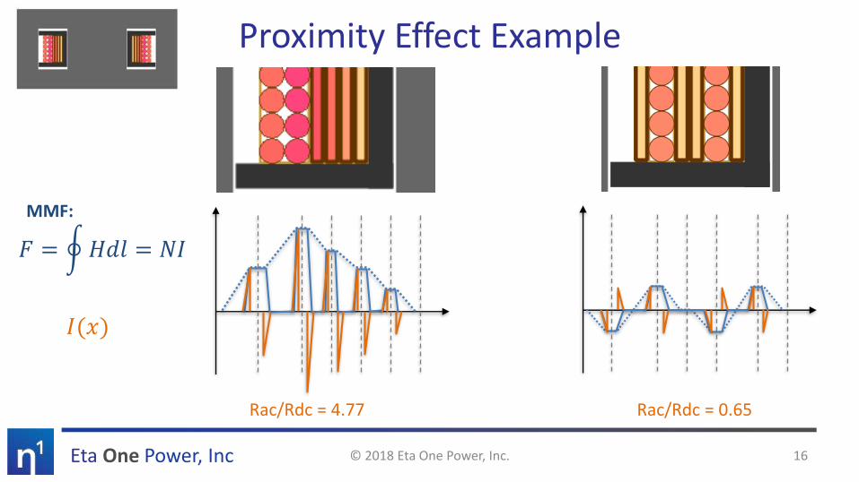
Rac/Rdc = 4.77 Rac/Rdc = 0.65
𝐹 = ර𝐻𝑑𝑙 = 𝑁𝐼
𝐼(𝑥)
MMF:

Eta One Power, Inc
𝐸𝑣 =1
2𝑩 ∙ 𝑯
AC Winding Losses: Fringe-Field EffectFlux Density (B) Field (H)𝑩 = 𝜇𝑯
Current Density (J)
[1] Finite Element Method Magnetics: http://www.femm.info
© 2018 Eta One Power, Inc. 17

Eta One Power, Inc
Magnetic Structures : H FieldsDistributed gap materials contain flux but distribute fringe field
Example: 120 µH, 45W offline flyback transformer @ 500 kHz, RM8/I core, losses at fundamental current only in FEMM
Loss: 337mW Loss: 188mW
Standard Ferrite Distributed Gap Powdered Material
Loss: 360mW
© 2018 Eta One Power, Inc. 18
• Single gap can cause large fringing losses in nearby windings
• Distributed gap effective at reducing fringing fields and losses while keeping flux contained in core
• Ungapped material (e.g. powdered iron) not effective in Pot-core shapes in constraining flux.• Fringing fields extend into window, not near gap
• Likely much better in toroid geometries

Eta One Power, Inc
Examining Winding Location: Eta Designer
Winding Loss: 382 mWWinding Loss: 544 mW Winding Loss: 308 mW
See [2]: Hu, Sullivan, “Optimization of shapes for round-wire high-frequency gapped-inductor windings,” IEEE Ind. Appl. Soc. Annual Meeting 1998.
© 2018 Eta One Power, Inc. 19
85-265 VAC to 20V/2.25A Flyback @ 500 kHz

Eta One Power, Inc
Examining Winding Location: FEMM
Winding Loss: 337 mWWinding Loss: 560 mW Winding Loss: 226 mW
See [2]: Hu, Sullivan, “Optimization of shapes for round-wire high-frequency gapped-inductor windings,” IEEE Ind. Appl. Soc. Annual Meeting 1998.
© 2018 Eta One Power, Inc. 20
85-265 VAC to 20V/2.25A Flyback @ 500 kHz

Eta One Power, Inc
Approach to Simulating Fringe-Field (& Proximity) Losses
1) Determine H field at wire / winding turn locations2) Compute AC loss for specific wire given H field [3-5]
DC FEM Simulation determines external H
𝑃𝑒𝑥𝑡 =𝐺(𝑔𝑒𝑜𝑚𝑒𝑡𝑟𝑦)
𝜎𝐻2
3) Add in skin depth loss, DC Loss, core loss4) Evaluate and optimize magnetic structure…
[3] Sullivan, “Computationally Efficient Winding Loss Calculation with Multiple Windings, Arbitrary Waveforms, and Two-Dimensional or Three-Dimensional Field Geometry,” IEEE Trans. Power. Elec. Jan 2001[4] Nan, Sullivan, “Simplified High-Accuracy Calculation of Eddy-Current Loss in Round-Wire Windings,” IEEE PESC 2004[5] Zimmanck, Sullivan, “Efficient Calculation of Winding-Loss Resistance Matrices for Magnetic Components,” IEEE COMPEL 2010
© 2018 Eta One Power, Inc. 21

Eta One Power, Inc
Winding Capacitances
© 2018 Eta One Power, Inc. 22
+–
VIN IOUT
Intrawinding capacitance:• Distributed capacitance between turns of same
winding• “Lumped” capacitance falls across switching node,
adds to switching loss• Leads to ringing in circuit and other resonant modes
Interwinding capacitance:• Distributed capacitance between different windings• Capacitive charge injection across barrier• Leads to common-mode noise injected into output,
trouble at the EMC lab

Eta One Power, Inc
Reducing Winding Capacitance
© 2018 Eta One Power, Inc. 23
Reducing intrawinding capacitance:• Reduce ∆V between adjacent turns• Single-layer windings• Wind two-layer windings in same direction• Stagger-wind to avoid large overlap ∆V
Reducing interwinding capacitance:• Minimize interleaving between windings
• Counter to minimizing proximity loss
• Space windings apart with tape / insulation• Add shielding layer

Eta One Power, Inc
Buck Converter: Inductor Scaling
Frequency%
Rip
ple Larger Cores
Saturation Limited:• Core Loss is a small % of total
• Smaller gap and lower flux ripple
• Fringing effects minimal
Core Loss Limited:• Significant ripple and energy stored in core
• Fringing and skin effects must be considered
© 2018 Eta One Power, Inc. 24
Time
Ind
uct
or
Cu
rren
t

Eta One Power, Inc
Magnetics scaling: Generalization
© 2018 Eta One Power, Inc. 25
Goal: Create a representation of power capability (via V-A product) for a general magnetic
ref: Sullivan, et. al. “On Size and Magnetics: Why Small Efficient Power Inductors are Rare,” IEEE 3D-PEIM 2016
𝑉𝐴 = 𝑉 ∙ 𝐼 = 𝑁𝑓𝐵0𝐴𝑐𝐽0𝐴𝑤𝑁
= 𝑓(𝐵0𝐽0)(𝐴𝑐𝐴𝑤)
Power handling capability
Applied voltage & winding current
Max current density in winding window
Max flux in core
For low frequency operation, saturation limited and for a linear dimension α:
• Power is proportional to α4 – power density improves with magnetic size
• Power is proportional to frequency f (B0 = Bsat)

Eta One Power, Inc
Magnetics Scaling: Frequency
© 2018 Eta One Power, Inc. 26
Operating Condition Power Densityby Size
Power Densityby Frequency
Low freq, saturation limited, fixed temp rise α1 f1
Low freq, core loss limited, fixed temp rise α0 to α0.2 * f B0(f)
High freq, core loss limited, fixed temp rise α-0.5 to α-0.3 * ∼f0.5 B0(f)
ref: Sullivan, et. al. “On Size and Magnetics: Why Small Efficient Power Inductors are Rare,” IEEE 3D-PEIM 2016
* based on Steinmetz β for core material @ frequency (β = 2 to 3)
Material performance factor

Eta One Power, Inc
CASE STUDY:FLYBACK CONVERTER
© 2018 Eta One Power, Inc. 27
Eta One Power, Inc
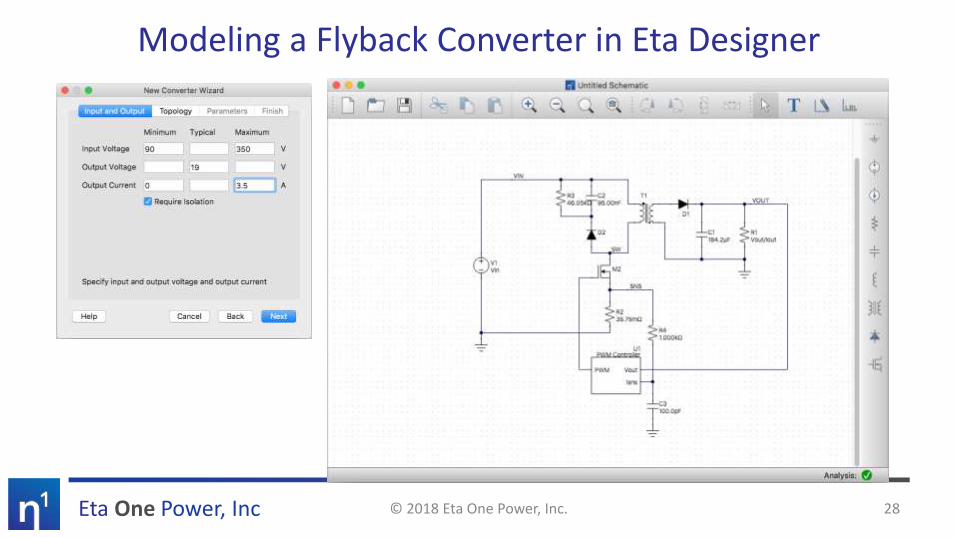
Modeling a Flyback Converter in Eta Designer
© 2018 Eta One Power, Inc. 28

Eta One Power, Inc
Modeling a Flyback Converter in Eta Designer (2)
© 2018 Eta One Power, Inc. 29

Eta One Power, Inc
Designing Flyback Magnetics
© 2018 Eta One Power, Inc. 30
1. Choose core geometry and material
2. Choose gap size, mag. inductance and/or turn count
3. Add an auxiliary winding
4. Edit windings as needed
5. Drag windings and add tape to arrange as desired

Eta One Power, Inc
Flyback: Simulation vs. Bench
© 2018 Eta One Power, Inc. 31
65W Universal AC to 19V Flyback ConverterLM5023 Valley-mode flyback controller EVM
In E
ta D
esi
gne
r:
Total Loss: 2.68 W @ 3 A

Eta One Power, Inc
Flyback: Simulation vs. Bench (2)
© 2018 Eta One Power, Inc. 32
Measured: From EVM Datasheet
Simulated: From Eta Designer
78%
80%
82%
84%
86%
88%
90%
92%
0.5 1 1.5 2 2.5 3 3.5
Effi
cien
cy
Output Current [A]
115 VAC230 VAC
Sim w/o AC losses
Sim w/ AC losses
Measured results
Eta One Power, Inc
CASE STUDY: LLC CONVERTER
© 2018 Eta One Power, Inc. 33
Eta One Power, Inc
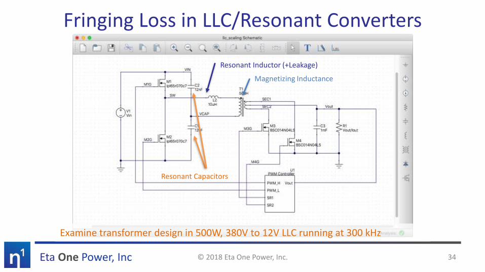
Fringing Loss in LLC/Resonant Converters
Resonant Capacitors
Resonant Inductor (+Leakage)
Magnetizing Inductance
© 2018 Eta One Power, Inc. 34
Examine transformer design in 500W, 380V to 12V LLC running at 300 kHz
Eta One Power, Inc
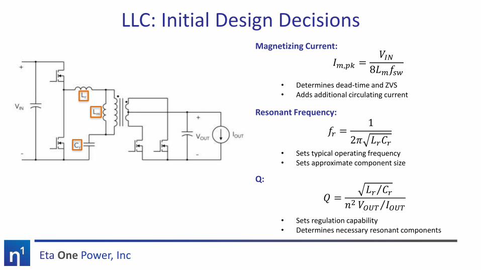
LLC: Initial Design DecisionsMagnetizing Current:
• Determines dead-time and ZVS• Adds additional circulating current
Resonant Frequency:
• Sets typical operating frequency• Sets approximate component size
Q:
• Sets regulation capability• Determines necessary resonant components
𝐼𝑚,𝑝𝑘 =𝑉𝐼𝑁
8𝐿𝑚𝑓𝑠𝑤
𝑓𝑟 =1
2𝜋 𝐿𝑟𝐶𝑟
𝑄 =Τ𝐿𝑟 𝐶𝑟
𝑛2 Τ𝑉𝑂𝑈𝑇 𝐼𝑂𝑈𝑇

Eta One Power, Inc
LLC Waveforms (at resonance)
Primary switch-node voltagePrimary resonant current
Secondary-side currents
Gating Waveforms
ZVSZVS
ZCS
© 2018 Eta One Power, Inc. 36

Eta One Power, Inc
LLC Silicon vs. GaN: Magnetic EffectsSilicon Version:
70 mΩ 650V SuperjunctionCr: 24nF, Lr: 10µH, Lm: 50µH
GaN Version:67 mΩ 650V e-mode GaN
Cr: 24nF, Lr: 10µH, Lm: 200µH
16:1CT on 8L x 140 um PCB in EQ25+PLT-3F36
Total Winding Loss: 5.43 W16:1CT on 8L x 140 um PCB in EQ25+PLT-3F36
Total Winding Loss: 2.991 W
© 2018 Eta One Power, Inc. 37
Eta One Power, Inc
Conclusions• Magnetics design is complex with many tradeoffs
– Custom designs are needed for almost every power supply
• Magnetic design comes down to understanding losses and their tradeoff in the context of the specific power converter– Easy: DC winding loss– Medium: Core loss (but non-sinusoidal waveforms are hard)– Hard: Skin-depth, proximity and fringe-field losses
• Understanding the trends in magnetics design can help drive converter design decisions
• Software like Eta Designer helps designers understand the tradeoffs easily to quickly develop an optimized solution.
© 2018 Eta One Power, Inc. 38