Embed Size (px)
Citation preview

Tekla StructuresSystem Guide
Product version 21.0March 2015
©2015 Tekla Corporation
Contents
1 Optimizing Tekla Structures performance...................................................... 51.1 System memory......................................................................................................................... 51.2 Graphics card.............................................................................................................................61.3 Modeling tips for large models............................................................................................... 6
2 Tekla Open API...................................................................................................8
3 Files and folders.................................................................................................93.1 Initialization files....................................................................................................................10
Typical initialization files and their reading order................................................................................................. 10Global default environment settings - env_global_default.ini.......................................................................... 14Local environment settings - env_<environment>.ini..........................................................................................14Role settings - role_<role>.ini.....................................................................................................................................14 Modifying the user.ini file ...........................................................................................................................................15Creating customized initialization files and startup shortcuts.......................................................................... 16Initialization files included in customized initialization files............................................................................. 18
3.2 Files storing options and advanced options.........................................................................18Settings in the Options dialog box............................................................................................................................. 19Settings defined by advanced options.......................................................................................................................32List of user-specific advanced options...................................................................................................................... 33 Changing advanced option settings .........................................................................................................................38
3.3 Input files................................................................................................................................ 39Customizing user-defined attributes......................................................................................................................... 39The environment database file.....................................................................................................................................40Updating definitions of user-defined attributes in a model............................................................................... 41Objects.inp properties.....................................................................................................................................................41User-defined attributes affecting numbering......................................................................................................... 43Example: Creating and updating a user-defined attribute..................................................................................43Showing plates as flat bars in drawings and reports............................................................................................ 46Defining flat bar sizes with Fltprops.inp................................................................................................................... 47Defining unfolding parameters.................................................................................................................................... 47Unfolding parameter properties.................................................................................................................................. 48
3.4 Data files................................................................................................................................. 493.5 Message files...........................................................................................................................50
Customizing message files............................................................................................................................................ 50Example: Modifying a message file............................................................................................................................ 51
3.6 Standard files..........................................................................................................................51List of standard files saved with Save defaults command...................................................................................52
3.7 Properties files........................................................................................................................ 523.8 Catalog files............................................................................................................................ 533.9 Font files..................................................................................................................................54
2

3.10 Symbol files.............................................................................................................................553.11 Files related to templates, reports and drawings................................................................553.12 Image files............................................................................................................................... 563.13 Log files................................................................................................................................... 57
Viewing a log file............................................................................................................................................................. 58Viewing parts listed in a log file..................................................................................................................................59The numbering.history log file..................................................................................................................................... 59Numbering series in the numbering.history log file.............................................................................................. 61
3.14 Model folder files and file name extensions....................................................................... 623.15 Checking and changing Tekla Structures file and folder locations (Directory
Browser)...................................................................................................................................833.16 Folder search order.................................................................................................................843.17 Project and firm folders.........................................................................................................863.18 Location of environment files............................................................................................... 873.19 Location of certain files in hidden folders...........................................................................873.20 Macros..................................................................................................................................... 89
Recording, editing and running macros.................................................................................................................... 89Adding a customized toolbar button for a macro.................................................................................................. 90
4 Model dump..................................................................................................... 914.1 Exporting a model dump........................................................................................................914.2 Importing a model dump........................................................................................................92
5 Disclaimer.........................................................................................................93
3

4
1 Optimizing Tekla Structuresperformance
To optimize Tekla Structures performance, you should consider the following items especiallywhen you are handling large and complex models:
• your hardware setup
• Speed and Accuracy settings in the Advanced Options dialog box.
• modeling practices.
For more detailed information on hardware setup, see hardware recommendations in TeklaUser Assistance Support Articles: Hardware recommendations
See also the Hardware and operating system topics on the Tekla Discussion Forum.
System memory on page 5
Graphics card on page 5
Modeling tips for large models on page 6
1.1 System memoryLarge models consume more memory. As a 64-bit system is able to utilize more memory thana 32-bit system, 64-bit Tekla Structures on a 64-bit operating system is recommended.
Optimizing Tekla Structures performance on page 5
See also
See also
Optimizing Tekla Structures performance 5 System memory
1.2 Graphics cardRendering in Tekla Structures uses OpenGL technology, so graphics cards with good hardwaresupport for OpenGL give the best performance. Up-to-date display drivers are very importantso you should regularly check that you have the latest driver installed.
If you suspect that your graphics card is causing problems with displaying objects, set the XS_USE_SOFTWARE_RENDERING advanced option to TRUE. This may solve the displayproblems but may reduce performance.
You can test your graphics card performance with Steelmark, an application developed byTekla. Steelmark tests how fast your computer handles graphical information typically used inTekla Structures. You can download Steelmark on the Tekla Extranet.
XS_USE_SOFTWARE_RENDERING
Optimizing Tekla Structures performance on page 5
Tekla Structures graphics hardware test
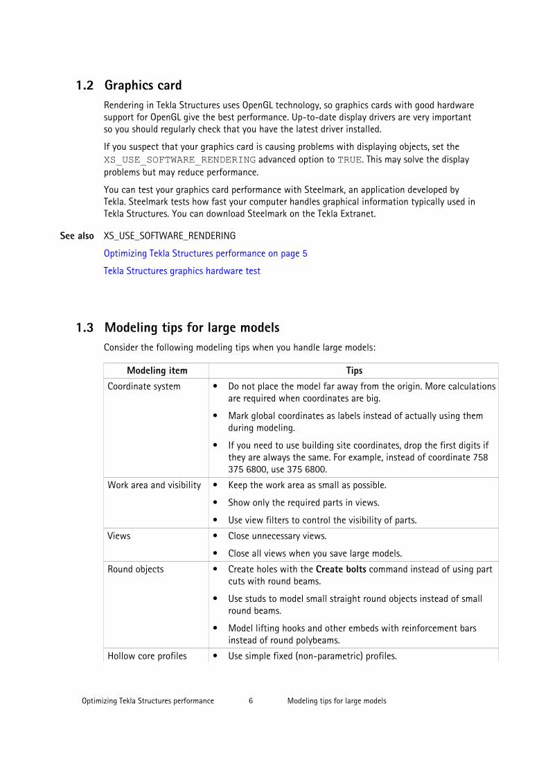
1.3 Modeling tips for large modelsConsider the following modeling tips when you handle large models:
Modeling item TipsCoordinate system • Do not place the model far away from the origin. More calculations
are required when coordinates are big.
• Mark global coordinates as labels instead of actually using themduring modeling.
• If you need to use building site coordinates, drop the first digits ifthey are always the same. For example, instead of coordinate 758375 6800, use 375 6800.
Work area and visibility • Keep the work area as small as possible.
• Show only the required parts in views.
• Use view filters to control the visibility of parts.
Views • Close unnecessary views.
• Close all views when you save large models.
Round objects • Create holes with the Create bolts command instead of using partcuts with round beams.
• Use studs to model small straight round objects instead of smallround beams.
• Model lifting hooks and other embeds with reinforcement barsinstead of round polybeams.
Hollow core profiles • Use simple fixed (non-parametric) profiles.
See also
Optimizing Tekla Structures performance 6 Modeling tips for large models

Modeling item Tips• Use chamfers for curved corners.
Custom components • Do not create overly complex custom components. When used ingreat numbers they consume a lot of memory.
Numbering • Do not number the whole model in one go. Numbering all objectsin large models may take a considerable amount of time.
Model database • If your model file is getting large, repairing the model database canhelp to reduce the file size considerably and therefore help withmemory problems.
Firm and Projectfolders
• Save Firm and Project folders locally on the hard drive of yourcomputer instead of a network drive. This saves time if networkspeed is slow.
When working in the multi-user mode, ensure that the folders aresynchronized on all users’ hard drives so that important data is notlost or changed.
See also
Optimizing Tekla Structures performance 7 Modeling tips for large models

2 Tekla Open API
Tekla Open API is a specialized Application Programming Interface (API) developed by Teklathat enables you to develop applications and additional functionality on the Tekla modelingplatform and integrate it into your own environment. Tekla Open API is implemented usingMicrosoft .NET technology.
Applications that are developed with Tekla Open API to work in conjunction with TeklaStructures are called extensions.
With Tekla Open API you can:
• Record and run user interface actions
By recording and running user interface actions you can automate routine tasks, such ascreating daily reports.
• Create automation tools
You can create automation tools for frequently needed objects. With automation toolsyou can, for example, create basic structures or add typical details to drawings.
• Integrate Tekla Structures to other software
You can utilize the Tekla Open API and .NET in transferring information between TeklaStructures and other software, such as Analysis & Design software.
• Create new functionality
With Tekla Open API, you can create tools that add new functionality to Tekla Structures.
For more information on Tekla Open API and extensions, see:
• TeklaOpenAPI_Reference.chm help in the ..\ProgramData\TeklaStructures\<version>\help\enu folder
• .NET startup package in Tekla Downloads product download service.
• Extensions in Tekla Warehouse.
• Extensions in Tekla User Assistance.
Tekla Open API 8 Modeling tips for large models

3 Files and folders
This section explains where Tekla Structures stores information. It describes the file typesTekla Structures contains, where they are located, and how they should be used.
Tekla Structures contains a large amount of files that affect the way the software works. It isimportant to know which file controls which functionality, and also which files we do notrecommend that you touch.
The initialization file reading order is also very important. You need to know the order inwhich the files are read when you open Tekla Structures, so that you do not do unnecessarymodifications in the files.
Initialization files on page 10
Input files on page 38
Files storing options and advanced options on page 18
Data files on page 49
Message files on page 50
Standard files on page 51
Properties files on page 52
Catalog files on page 53
Font files on page 54
Symbol files on page 55
Files related to templates, reports and drawings on page 55
Image files on page 56
Log files on page 57
Model folder files and file name extensions on page 62
Checking and changing Tekla Structures file and folder locations (Directory Browser) on page82
Folder search order on page 84
Project and firm folders on page 86
See also
Files and folders 9 Modeling tips for large models

Location of environment files on page 87
Location of certain files in hidden folders on page 87
Macros on page 88
3.1 Initialization filesInitialization files are used for defining Tekla Structures start-up parameters and defaultsettings. They contain advanced options that are used for configuring Tekla Structures fordifferent standards, and for your or your company’s style of working.
Tekla Structures automatically creates the necessary initialization files during installation.Thenumber of initialization files it creates depends on how many country-specific environmentsyou choose to install.
Advanced Options Reference Guide
Typical initialization files and their reading order
Below is a list of all the typical initialization files that are read when Tekla Structures isstarted. The numbers indicate their reading order at startup. If there are conflicting settings,the ones read later override the ones read earlier.
Changing an advanced option value in .ini files located outside the modelfolder does not affect the existing models. You can only update advanced optionsin the Advanced Options dialog box or in the options.ini file located inmodel folder; not from an options.ini file located in folders defined for theadvanced options XS_FIRM or XS_PROJECT. The .ini files are read alsowhen you open an existing model, but only new advanced options that do notexist in options_model.db or options_drawings.db are inserted, forexample, such options that are not yet in the Advanced Options dialog box buthave been added in the software.
To check the files that have been read and their reading order, go to Tools -->Display Log File --> Session History .
See also
Files and folders 10 Initialization files

File and reading order Description1. fonts_<lang>.ini This file is optional, and it is only needed for languages using
special characters. One example is the fonts_jpn.ini filefor the Japanese language.
This file is read from Tekla Structures\<version>\nt\bin\ if it is available. It is installed to the ..\nt\binfolder when Tekla Structures is installed.
NOTE: Do not change these settings.
2.teklastructures.ini
The file teklastructures.ini starts Tekla Structures. It isread from ..\Program Files\Tekla Structures\<version>\nt\bin\.
This file contains basic system settings, such as the location ofsoftware and environment files. This file is installed to the ..\nt\bin folder when Tekla Structures is installed. It is alwaysread at Tekla Structures startup.
NOTE: Do not change these settings.
3. lang_<lang>.ini This file contains the language settings. It is read from ..\Program Files\Tekla Structures\<version>\nt\bin\.
This file is installed to the ..\nt\bin folder when TeklaStructures is installed.
Which lang_<lang>.ini files exist in the ..\nt\binfolder depends on which languages you have selected to installduring the software installation.
The language that is read depends on the language you haveselected in Tools --> Select Language in the previous TeklaStructures session.
NOTE: Do not change these settings.
4.env_global_default.ini
This file is used as a default for all environments and containsthe global settings. The settings in theenv_global_default.ini provide the basics for allenvironment settings globally. The settings in this file can belocalized and specified differently in an environment-specificinitialization file that is read later than this file.
This file is always read at Tekla Structures startup from ..\ProgramData\Tekla Structures\<version>\environments\common\ and is installed there from thecommon environment installation package.
NOTE: Do not change these settings.
Files and folders 11 Initialization files

File and reading order Description5. env_<environment>.ini
The env_<environment>.ini files contain all theadvanced options that have environment-specific settings. Theyare read from ..\ProgramData\Tekla Structures\<version>\environments\<environment>\.
The env_<environment>.ini files that exist on yourcomputer depends on which environment packages you haveinstalled. Which env_<environment>.ini file is readdepends on the environment that you select in the TeklaStructures the startup dialog box.
For example, this file defines that the US imperial environmentuses imperial units, shows the fractions correctly, andunderstands input as imperial. In metric environments metricunits are used.
NOTE: Do not change these settings.
6. role_<role>.ini The role_<role>.ini files contain all the advancedoptions that have typical role-specific settings. They are readfrom ..\ProgramData\Tekla Structures\<version>\environments\<environment>\.
The available roles depend on the environments you haveinstalled.
You can select the role in the Tekla Structures the startup dialogbox.
NOTE: Do not change these settings.
7. All .ini files defined inshortcut/command line with -i <name>.ini
Usually none.
8. company.ini The company.ini file is useful especially for big companiesthat want to unify certain enterprise-level settings. This file isread from a folder specified with the advanced option XS_COMPANY_SETTINGS_DIRECTORY. This file is readonly if the advanced option XS_COMPANY_SETTINGS_DIRECTORY is set.
This file is created by the system administrator when necessary,it is not created by the installation.
9. user.ini The user.ini file is where you can save your personal usersettings.
This file is located in the same location as the user-specificoptions.bin file, for example, C:\Users\<user>\AppData\Local\Tekla Structures\<version>\UserSettings.
Files and folders 12 Initialization files

File and reading order DescriptionThe user.ini is created in the above mentioned locationwhen you start Tekla Structures for the first time and create andsave a model using the current version. It is read when you startTekla Structures.
The changes you make in the advanced options in the AdvancedOptions dialog box override the settings in all other initializationfiles, if the advanced option exists in both locations.
If user.ini has system options they are read always whenTekla Structures is opened.
If user.ini has model-specific options they are used whennew model is created.
If user.ini has user-specific options they are used whenTekla Structures is used for the first time.
10. options.ini in systemfolder
The folder is specified with the advanced option XS_SYSTEM.
11. options.ini, firm-specific, if any exits
12. options.ini, project-specific, if any exist
The option.ini files containing firm- or project-specificmodel settings are saved in and read from user-defined locationsspecified with the advanced options XS_FIRM and XS_PROJECT. They work in the specified way for the firm inquestion, or for the specified project if the model has been setup to read settings from these locations, and if the user hasmanually moved the options.ini file to these locations. Anoptions.ini is created in the firm or project folder whenyou copy or move it there.
Updating of model-specific and user-specific advanced optionscan only be done from the Advanced Options dialog box oroptions.ini located in model folder, not from the firm- orproject-specific options.ini files.
The options.ini in the firm or project folder is read whenyou start Tekla Structures or open the model.
13. options.ini, model-specific
The options.ini in the model folder.
Settings defined by advanced options on page 32
Creating customized initialization files and startup shortcuts on page 16
See also
Files and folders 13 Initialization files

Global default environment settings - env_global_default.ini
Do not modify the env_global_default.ini file. If you need to modifysome environment settings, copy the needed advanced options from this file toyour user.ini file and modify the settings there, or modify the settings in theAdvanced Options dialog box.
This file defines the global defaults for advanced options. Please see the environment settingsfile env_<environment name>.ini and the role settings file role_<rolename>.ini files for advanced options that are set according to your local standards. Thelocal files override the advanced options set in env_global_default.ini.
If the advanced option in the file is preceded by "rem", the software defaults are used andshown as the value. The outdated advanced options are listed at the end of the file.
Typical initialization files and their reading order on page 10
Local environment settings - env_<environment>.ini
Do not modify the env_<environment>.ini file. If you need to modifysome settings, copy the needed advanced options from this file to youruser.ini file and modify the settings there, or modify the settings in theAdvanced Options dialog box.
This file contains advanced options that are set according to local standards and are differentfrom the global defaults. The Global default environment settings fileenv_global_defaults.ini contains a complete listing of advanced options. Thelocal files override the advanced options set in env_global_default.ini .
Typical initialization files and their reading order on page 10
Role settings - role_<role>.ini
Do not modify the role_<role>.ini file. If you need to modify somesettings, copy the needed advanced options from this file to your user.ini file
See also
See also
Files and folders 14 Initialization files

and modify the settings there, or modify the settings in the Advanced Optionsdialog box.
This file contains advanced options that are set according to typical role requirements in yourlocal area. These settings are different from your environment settings inenv_<environment>.ini. The global default environment settings fileenv_global_defaults.ini contains a complete listing of advanced options. Theadvanced option settings in role_<role>.ini override the ones inenv_<environment>.ini
Typical initialization files and their reading order on page 10
Modifying the user.ini file
We recommend that you add in the user.ini file only system-specificadvanced options. You can also add model-specific advanced options, but thesesettings only affect new models that you create. Putting user-specific advancedoptions in user.ini may not work as desired as options.bin is loadedafter user.ini and may override the value.
To add an advanced option in the user.ini file:
1. Right-click the user.ini file in Windows Explorer and click Open with.... Select astandard text editor from the list of available programs.
2. On a new line, enter set, then a space, then the name of the advanced option followedby an equal sign, and then the value in a single line.
Tekla Structures only reads lines in the initialization file that start with set.
3. Save user.ini.
4. Restart Tekla Structures for the changes to take effect.
Possible values ExampleTRUEFALSE
set XS_DISABLE_WELD_PREP_SOLID=TRUEsetXS_UNDERLINE_AFTER_POSITION_NUMBER_IN_HARDSTAMP=FALSE
1 set XS_SINGLE_CLOSE_DIMENSIONS=10 set XS_SINGLE_USE_WORKING_POINTS=0string value set
XS_USER_DEFINED_BOLT_SYMBOL_TABLE=bolt_symbol_table.txt
See also
Files and folders 15 Initialization files
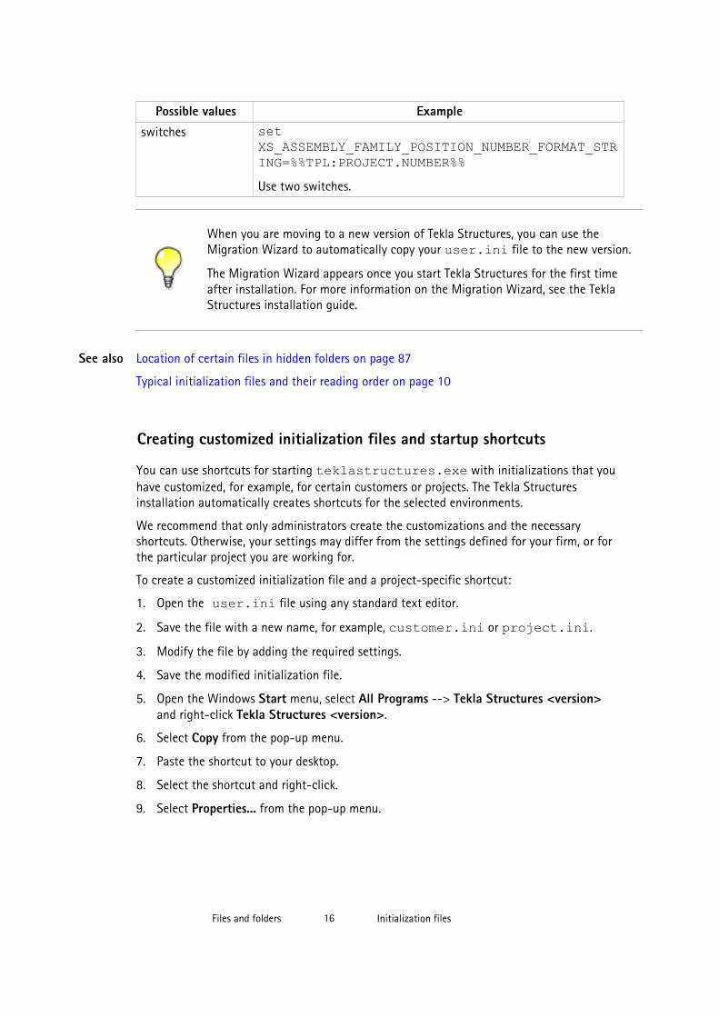
Possible values Exampleswitches set
XS_ASSEMBLY_FAMILY_POSITION_NUMBER_FORMAT_STRING=%%TPL:PROJECT.NUMBER%%Use two switches.
When you are moving to a new version of Tekla Structures, you can use theMigration Wizard to automatically copy your user.ini file to the new version.
The Migration Wizard appears once you start Tekla Structures for the first timeafter installation. For more information on the Migration Wizard, see the TeklaStructures installation guide.
Location of certain files in hidden folders on page 87
Typical initialization files and their reading order on page 10
Creating customized initialization files and startup shortcuts
You can use shortcuts for starting teklastructures.exe with initializations that youhave customized, for example, for certain customers or projects. The Tekla Structuresinstallation automatically creates shortcuts for the selected environments.
We recommend that only administrators create the customizations and the necessaryshortcuts. Otherwise, your settings may differ from the settings defined for your firm, or forthe particular project you are working for.
To create a customized initialization file and a project-specific shortcut:
1. Open the user.ini file using any standard text editor.
2. Save the file with a new name, for example, customer.ini or project.ini.
3. Modify the file by adding the required settings.
4. Save the modified initialization file.
5. Open the Windows Start menu, select All Programs --> Tekla Structures <version>and right-click Tekla Structures <version>.
6. Select Copy from the pop-up menu.
7. Paste the shortcut to your desktop.
8. Select the shortcut and right-click.
9. Select Properties... from the pop-up menu.
See also
Files and folders 16 Initialization files

10. Modify the Target of the shortcut by adding the required project initializationinformation to it.
First enter the path to the current teklastructures.exe, then the desiredparameters. In the following example, the name of the customized initialization file isproject1.ini.
You can use the following parameters in shortcuts:
• -i <initialization_file>: The initialization file to be read during startupafter the <role>.ini file, for example, -i \\MyServer\MyProject\Project1.ini. You can repeat this parameter as many times as you need, andthis way enter as many initialization files you need.
• <model_to_be_opened>: Full path to the model to be opened automatically,for example, "C:\TeklaStructuresModels\New model 1".
Files and folders 17 Initialization files

The settings in user.ini and option.ini files override the settings defined in theshortcuts using the parameter -i <initialization_file>The maximum length of a shortcut is 256 characters. If you have problems with the length,you can call all other necessary initialization files from your customized initialization fileinstead of adding them to the shortcut.
Initialization files included in customized initialization files on page 18
Typical initialization files and their reading order on page 10
Initialization files included in customized initialization filesInitialization files can include or call other initialization files. You can use this functionalityto create shortcuts for different purposes, for example, to have customized setup filesdepending on the client you are working for in a project such as fabricators.
Below is an example of a customized project initialization file that calls other initializationfiles.
MyProject.ini
The project shortcut for MyProject:
C:\ProgramFiles\Tekla Structures\19.0\nt\bin\TeklaStructures.exe -i \\MyServer\MyProject\MyProject.ini \\MyServer\MyProject\MyModel\MyModel.db1
Creating customized initialization files and startup shortcuts on page 16
3.2 Files storing options and advanced options
When a new model is created, Tekla Structures reads model-specific option and advancedoption values from the standard.opt file, and from the .ini files in a certain readingorder, and creates the databases options_model.db and options_drawings.db,and the options.ini file under the model folder.
When you change a model-specific option or advanced option and press OK or Apply in theOptions or Advanced Options dialog box, the settings are taken into use (otherwise you will
See also
See also
Files and folders 18 Files storing options and advanced options

get a warning message). The updated model-specific option or advanced option settings aresaved in options_model.db and options_drawings.db under model folder whenthe model is saved. In addition, there are also some special model-specific advanced optionsthat can be updated from the options.ini file located in the model folder, for example,new advanced options that are not yet in the Advanced Options dialog box.
When you change a user-specific option or advanced option, and press OK or Apply in theOptions or Advanced Options dialog box, the settings are saved in options.bin in ..\Users\<user>\AppData\Local\Tekla Structures\<version>\UserSettings.
You can change model-specific advanced options only in the Advanced Options dialog boxor in the options.ini file that is located in model folder.
You can change user-specific advanced options only in the Advanced Options dialog box.
You can change model- and_user-specific options only in the Options dialog box manually orby loading standard.opt file values in the dialog box.
You can save your own settings in the Options dialog by using the Save button. Then thestandard.opt file is saved in the \attributes folder under the model folder.
You can create a complete list of advanced options in a text file by clicking Writeto file in the Advanced Options dialog box. The list shows the name of theadvanced option, current value and type.
Changing an advanced option value in .ini files located outside the modelfolder does not affect the existing models. You can only update advanced optionsin the Advanced Options dialog box or in the options.ini file located inmodel folder; not from an options.ini file located in folders defined for theadvanced options XS_FIRM or XS_PROJECT. The .ini files are read alsowhen you open an existing model, but only new advanced options that do notexist in options_model.db or options_drawings.db are inserted, forexample, such options that are not yet in the Advanced Options dialog box buthave been added in the software.
Settings in the Options dialog box on page 19
Settings defined by advanced options on page 32
Settings in the Options dialog box
The Options dialog box (Tools > Options > Options...) contains the current values for anumber of Tekla Structures settings.
Check the settings before you start modeling and change them, if necessary.
See also
Files and folders 19 Files storing options and advanced options

The model-specific settings in this dialog box are saved in the options_model.db andoptions_drawings.db databases in the model folder, and the user-specific settings inoptions.bin in your local <user> folder.
You can also save your own settings by using the Save button. Then the standard.optfile is saved in the \attributes folder under model folder. You may want to copy this fileto your firm folder. When you create a model, the standard.opt is read from the firmfolder.
The options in the Options dialog box are described below.
Settings on this page are model-specific.
Option DescriptionClash check between bolt andbolted part
Defines whether the model is checked for clashes that occurbetween bolts and the related bolted parts.
If you select Yes, Tekla Structures will check the bolts against thereal geometry of the bolted part profiles including roundings, andusing the real bolt dimensions.
Defines the clash check clearance area for bolts.
If you do not enter a value, Tekla Structures uses the defaultvalue 1.00.
If you clear the check boxes, the clearance will be zero.
Defines the minimum clearance or the allowed overlap forreinforcing bars when they are checked against other reinforcingbars.
To allow reinforcing bars to overlap, enter a negative value.
If you clear the check box, the clearance will be zero.
Defines the reinforcing bar cover thickness.
Tekla Structures checks the cover thickness against the part thatthe reinforcing bar belongs to. Tekla Structures only checks thedistance from bar side to part surface. Tekla Structures does notcheck the distance from bar end to part surface. If the barpenetrates a part surface, a clash is reported, even if the bar iscompletely inside a cast unit or pour.
If you clear the check box, Tekla Structures will not check thecover thickness.
Tekla Structures uses the information on the Components tab when it creates parts usingcomponents.
Component properties defined in component dialog boxes override these settings. TeklaStructures only uses these settings if the corresponding boxes in the component dialog boxesare empty.
Clash check page
Componentspage
Files and folders 20 Files storing options and advanced options

If you change settings here, Tekla Structures only applies the new settings to componentsyou subsequently create. Components you created prior to changing the preferences are notaffected.
Settings on this page are model-specific.
Option DescriptionProfile names Defines parametric profile prefixes for plates. It is important that
profile names are set up correctly so that you can use filters andwizards effectively.
Profile names must exist in the profile catalog. If you want touse a parametric profile that does not have a name in thecatalog, first add it to the Profile Catalog, then enter it here.Tekla Structures uses the Folded plate prefix when you use thefolded plates in components.
Bolts In components, Tekla Structures uses Factor of bolt edgedistance and Compare edge distance to to check that the boltsit creates are not too close to the edge of a part, and warns youif they are. Check that Factor of bolt edge distance is setaccording to the standard you are using. The default edgedistance setting depends on your environment.
Compare edge distance defines whether the edge distancechecks are based on bolt or hole diameter.
To define the default bolt properties to use in connections, selecta Bolt standard and Bolt size.
Parts Part material defines the default part material grade.
Part start numbers defines start numbers for parts that areWelded to primary and Welded to secondary, Loose parts, andAssembly loose parts.
Cross-check these settings against the numbering series youdefine to make sure they do not overlap. If they overlap, TeklaStructures may create two non-identical parts with the samepart number. This generates an error in the log filenumbering.history.
Settings on this page are model-specific.
Option DescriptionExaggeration This setting defines the default values for Exaggeration limit
and Exaggeration scaling.
When you enable the exaggeration of the dimensions, a drawingdimension that is narrower than the defined limit is expanded.Exaggeration limit defines the default value for this limit.
Exaggeration scaling defines whether you are using Paper orModel as the exaggeration scaling method:
Drawingdimensions page
Files and folders 21 Files storing options and advanced options
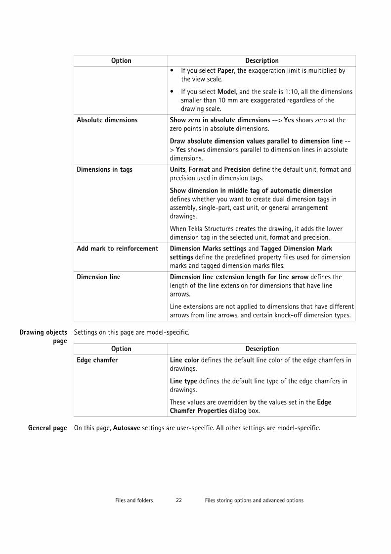
Option Description• If you select Paper, the exaggeration limit is multiplied by
the view scale.
• If you select Model, and the scale is 1:10, all the dimensionssmaller than 10 mm are exaggerated regardless of thedrawing scale.
Absolute dimensions Show zero in absolute dimensions --> Yes shows zero at thezero points in absolute dimensions.
Draw absolute dimension values parallel to dimension line --> Yes shows dimensions parallel to dimension lines in absolutedimensions.
Dimensions in tags Units, Format and Precision define the default unit, format andprecision used in dimension tags.
Show dimension in middle tag of automatic dimensiondefines whether you want to create dual dimension tags inassembly, single-part, cast unit, or general arrangementdrawings.
When Tekla Structures creates the drawing, it adds the lowerdimension tag in the selected unit, format and precision.
Add mark to reinforcement Dimension Marks settings and Tagged Dimension Marksettings define the predefined property files used for dimensionmarks and tagged dimension marks files.
Dimension line Dimension line extension length for line arrow defines thelength of the line extension for dimensions that have linearrows.
Line extensions are not applied to dimensions that have differentarrows from line arrows, and certain knock-off dimension types.
Settings on this page are model-specific.
Option DescriptionEdge chamfer Line color defines the default line color of the edge chamfers in
drawings.
Line type defines the default line type of the edge chamfers indrawings.
These values are overridden by the values set in the EdgeChamfer Properties dialog box.
On this page, Autosave settings are user-specific. All other settings are model-specific.
Drawing objectspage
General page
Files and folders 22 Files storing options and advanced options
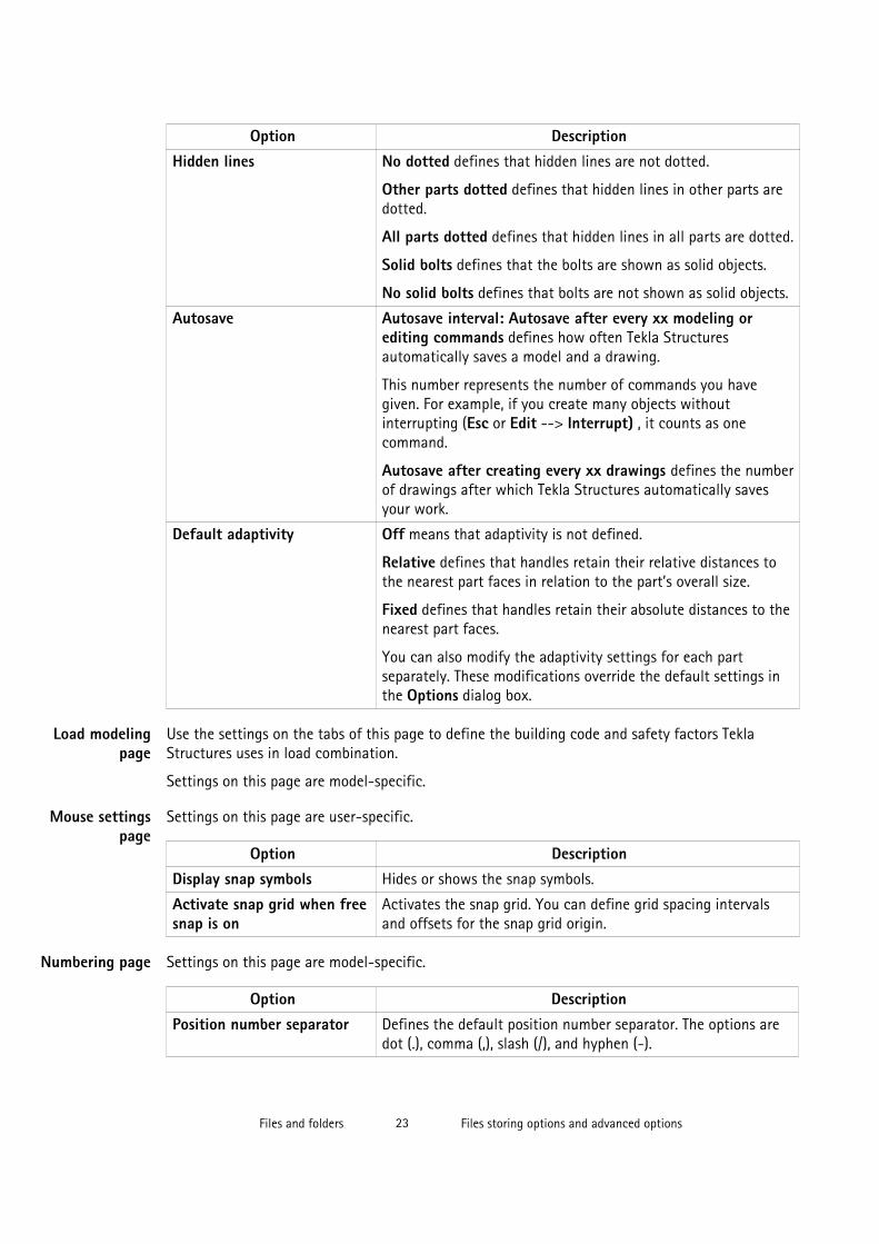
Option DescriptionHidden lines No dotted defines that hidden lines are not dotted.
Other parts dotted defines that hidden lines in other parts aredotted.
All parts dotted defines that hidden lines in all parts are dotted.
Solid bolts defines that the bolts are shown as solid objects.
No solid bolts defines that bolts are not shown as solid objects.
Autosave Autosave interval: Autosave after every xx modeling orediting commands defines how often Tekla Structuresautomatically saves a model and a drawing.
This number represents the number of commands you havegiven. For example, if you create many objects withoutinterrupting (Esc or Edit --> Interrupt) , it counts as onecommand.
Autosave after creating every xx drawings defines the numberof drawings after which Tekla Structures automatically savesyour work.
Default adaptivity Off means that adaptivity is not defined.
Relative defines that handles retain their relative distances tothe nearest part faces in relation to the part’s overall size.
Fixed defines that handles retain their absolute distances to thenearest part faces.
You can also modify the adaptivity settings for each partseparately. These modifications override the default settings inthe Options dialog box.
Use the settings on the tabs of this page to define the building code and safety factors TeklaStructures uses in load combination.
Settings on this page are model-specific.
Settings on this page are user-specific.
Option DescriptionDisplay snap symbols Hides or shows the snap symbols.
Activate snap grid when freesnap is on
Activates the snap grid. You can define grid spacing intervalsand offsets for the snap grid origin.
Settings on this page are model-specific.
Option DescriptionPosition number separator Defines the default position number separator. The options are
dot (.), comma (,), slash (/), and hyphen (-).
Load modelingpage
Mouse settingspage
Numbering page
Files and folders 23 Files storing options and advanced options

Option DescriptionRebar position numberseparator
Defines the default reinforcing bar position number separator.The options are dot (.), comma (,), slash (/), and hyphen (-).
Part number type Defines the default part number type. The options are Partnumber and Combined assembly / part number.
Settings on this page are model-specific.
Option DescriptionNorth direction Project north (degrees counter clockwise from global x)
defines which direction is north in the model. Enter the value indegrees counter-clockwise from the global x axis.
Part viewing direction Defines which direction parts are viewed from in drawings.
Beam skew limit
Column skew limit
Tekla Structures uses limit angles to determine whether a part isa beam or a column when creating orientation marks. TeklaStructures treats parts outside these limits as braces.
Parts skewed more than 80° are columns.
Parts skewed less than 10° are beams.
Preferred location for mark Defines the location of part marks in drawings, to the left orright end of the part.
Mark always to center ofcolumn
This setting only affects columns.
Yes places part marks in the center of columns in plan views. Toindicate part orientation, include compass direction (Facedirection) in the part mark instead.
No places part marks on the same flange in general arrangementand assembly drawings.
Orientationmarks page
Files and folders 24 Files storing options and advanced options

Units and decimals given on the Modeling and Catalogs tabs affect input. The units anddecimals given on the Analysis results tab affect the output data.
The settings on the Modeling tab affect the data that is used when you are modeling, forexample copying, moving, creating grids, creating points, etc. Settings on the Catalogs tabaffect the data stored in the profile and material catalogs.
Settings on the Units and decimals page do not have any effect on drawings or reports, oron the Inquire and Measure tools.
The number to the left of each option indicates the number of decimals.
The number of decimals affects the input and storage accuracy. Always use a sufficientnumber of decimals.
Settings on this page are model-specific.
Option DescriptionLength mm, cm, m, in (decimal), ft (decimal), ft-inAngle o, radSpring constant
Units anddecimals page
Files and folders 25 Files storing options and advanced options

Option DescriptionRot. spring constant
Factor Enter a value using the arrow buttons.
Force
Distributed load
Surface load
Files and folders 26 Files storing options and advanced options
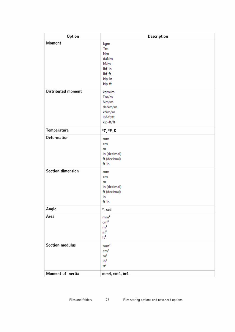
Option DescriptionMoment
Distributed moment
Temperature oC, oF, KDeformation
Section dimension
Angle o, radArea
Section modulus
Moment of inertia mm4, cm4, in4
Files and folders 27 Files storing options and advanced options

Option DescriptionRadius of inertia
Torsion constant mm4, cm4, in4Warping constant mm6, cm6, in6Cover area
Strength
Files and folders 28 Files storing options and advanced options

Option DescriptionModulus
Density
Weight
Strain o/oo, %Thermal dilat. coeff. 1/oC, 1/oF, 1/KRatio o/oo, %Volume
Length mm, cm, m, in (decimal), ft (decimal), ft-inAngle o, rad
Files and folders 29 Files storing options and advanced options
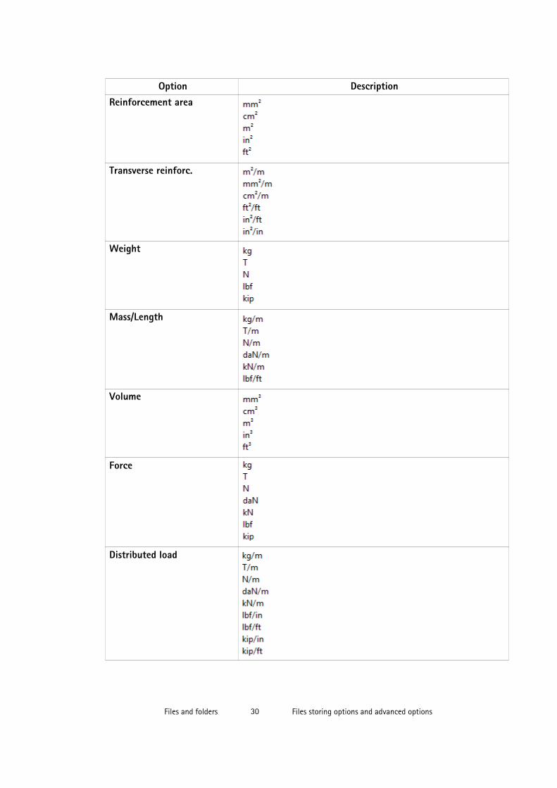
Option DescriptionReinforcement area
Transverse reinforc.
Weight
Mass/Length
Volume
Force
Distributed load
Files and folders 30 Files storing options and advanced options
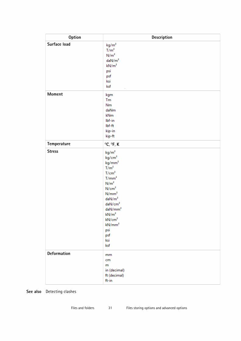
Option DescriptionSurface load
Moment
Temperature oC, oF, KStress
Deformation
Detecting clashesSee also
Files and folders 31 Files storing options and advanced options

Creating exaggerated dimensions
Automatic drawing-level dimensioning
Adding dual dimensions manually
Adding predefined reinforcement dimensions
Edge chamfers in drawings
Saving a model
Autosaving in multi-user mode
Modifying the shape of a reinforcement using adaptivity
Other snap switches
Defining a snap grid
Load combination properties
Displaying orientation marks (north marks)
Displaying compass direction
Mark location
Setting viewing direction for columns in assembly drawings
Setting viewing direction for beams and bracings in assembly drawings...
Files storing options and advanced options on page 18
Settings defined by advanced options
Advanced options can be user-, model-, system or role-specific:
• User-specific advanced options are saved in your local options.bin file, which is bydefault located in C:\Users\<user>\AppData\Local\Tekla Structures\<version>\UserSettings, and work in the specified way in all models that youhave. The folder can be changed using the advanced option XS_USER_SETTINGS_DIRECTORY. In the Advanced Options dialog box, the type isUSER. Some user-specific advanced options require restarting of Tekla Structures afterchanging the value.
• Model-specific advanced options work in the specified way only in the current model.They are saved to options_model.db and options_drawings.db undermodel folder. In the Advanced Options dialog box, the type is MODEL or DRAWING.Some special model-specific options that are not visible in the Advanced Options dialogbox can be changed from options.ini file under the model folder.
• System-specific advanced options are general to all sessions of Tekla Structures, andwork in the specified way for all users and in all models. In the Advanced Options dialogbox, the type is SYSTEM. A system-specific advanced option can be stored tooptions.ini under model folder by clicking SYSTEM next to the option andchanging it to MODEL(SYSTEM). Note that the changed value only works for the current
Files and folders 32 Files storing options and advanced options
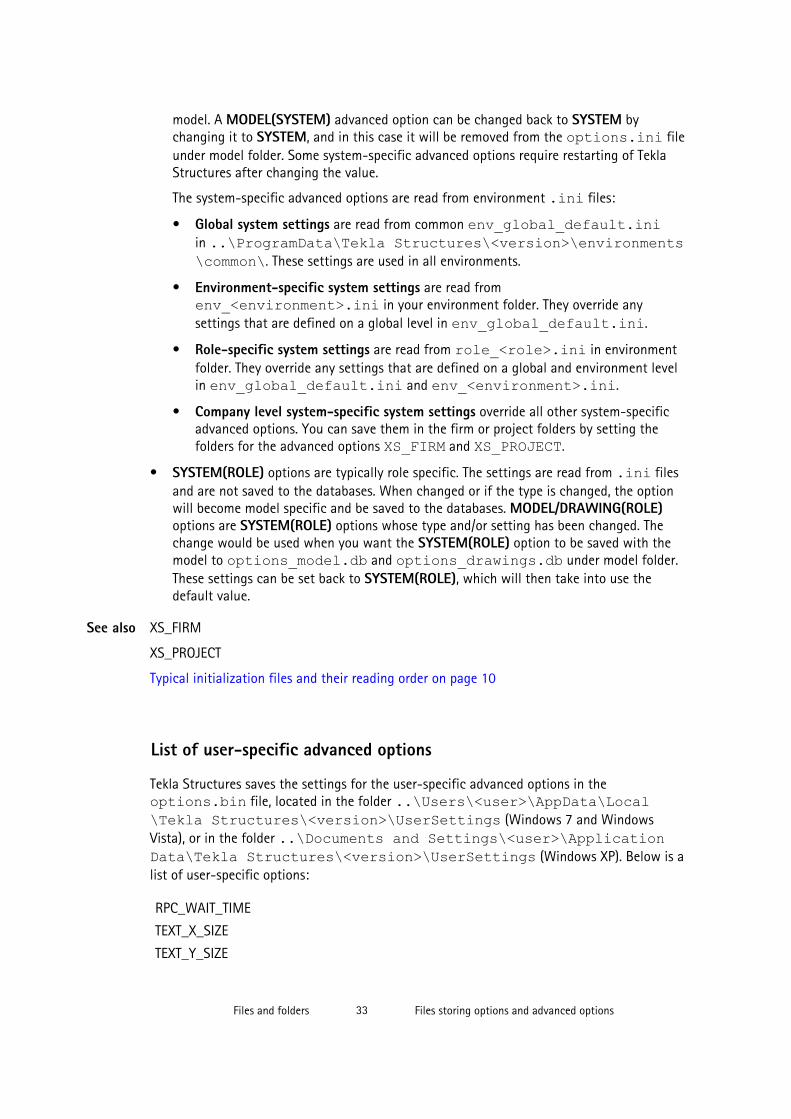
model. A MODEL(SYSTEM) advanced option can be changed back to SYSTEM bychanging it to SYSTEM, and in this case it will be removed from the options.ini fileunder model folder. Some system-specific advanced options require restarting of TeklaStructures after changing the value.
The system-specific advanced options are read from environment .ini files:
• Global system settings are read from common env_global_default.iniin ..\ProgramData\Tekla Structures\<version>\environments\common\. These settings are used in all environments.
• Environment-specific system settings are read fromenv_<environment>.ini in your environment folder. They override anysettings that are defined on a global level in env_global_default.ini.
• Role-specific system settings are read from role_<role>.ini in environmentfolder. They override any settings that are defined on a global and environment levelin env_global_default.ini and env_<environment>.ini.
• Company level system-specific system settings override all other system-specificadvanced options. You can save them in the firm or project folders by setting thefolders for the advanced options XS_FIRM and XS_PROJECT.
• SYSTEM(ROLE) options are typically role specific. The settings are read from .ini filesand are not saved to the databases. When changed or if the type is changed, the optionwill become model specific and be saved to the databases. MODEL/DRAWING(ROLE)options are SYSTEM(ROLE) options whose type and/or setting has been changed. Thechange would be used when you want the SYSTEM(ROLE) option to be saved with themodel to options_model.db and options_drawings.db under model folder.These settings can be set back to SYSTEM(ROLE), which will then take into use thedefault value.
XS_FIRM
XS_PROJECT
Typical initialization files and their reading order on page 10
List of user-specific advanced options
Tekla Structures saves the settings for the user-specific advanced options in theoptions.bin file, located in the folder ..\Users\<user>\AppData\Local\Tekla Structures\<version>\UserSettings (Windows 7 and WindowsVista), or in the folder ..\Documents and Settings\<user>\ApplicationData\Tekla Structures\<version>\UserSettings (Windows XP). Below is alist of user-specific options:
RPC_WAIT_TIME
TEXT_X_SIZE
TEXT_Y_SIZE
See also
Files and folders 33 Files storing options and advanced options

XS_ALWAYS_CONFIRM_SAVE_WHEN_CLOSING_DRAWING
XS_ALWAYS_CONFIRM_SAVE_WHEN_EXIT
XS_AUTOMATIC_NEW_MODEL_NAME
XS_AUTOMATIC_USER_FEEDBACK_SENDING_INTERVAL
XS_AUTOSAVE_DIRECTORY
XS_BACKGROUND_COLOR1
XS_BACKGROUND_COLOR2
XS_BACKGROUND_COLOR3
XS_BACKGROUND_COLOR4
XS_BASICVIEW_HEIGHT
XS_BASICVIEW_POSITION_X
XS_BASICVIEW_POSITION_Y
XS_BASICVIEW_WIDTH
XS_BLACK_DRAWING_BACKGROUND
XS_CHAMFER_DISPLAY_LENGTH_FACTOR
XS_CHANGE_DRAGGED_DIMENSIONS_TO_FIXED
XS_CHANGE_DRAGGED_MARKS_TO_FIXED
XS_CHANGE_DRAGGED_NOTES_TO_FIXED
XS_CHANGE_DRAGGED_TEXTS_TO_FIXED
XS_CHANGE_DRAGGED_VIEWS_TO_FIXED
XS_CHECK_BOLT_EDGE_DISTANCE_ALWAYS
XS_CIS_DEP1_EXPRESS_FILE
XS_CLONING_TEMPLATE_DIRECTORY
XS_COMPONENT_CATALOG_COLLECTION_NAME_LENGTH
XS_COMPONENT_CATALOG_THUMBNAIL_SIZE
XS_CREATE_ALSO_BIG_HTML_REPORT_PICTURES
XS_CREATE_DRAWING_PREVIEW_AUTOMATICALLY
XS_DEFAULT_FONT
XS_DEFAULT_FONT_SIZE
XS_DEFAULT_FONT_SIZE_GRID
XS_DISABLE_ANALYSIS_AND_DESIGN
XS_DISABLE_CIS2
XS_DISABLE_CLASSIFIER_FOR_MODIFIED_PARTS
XS_DISABLE_MASTER_DRAWING_CATALOG
XS_DISABLE_PARTIAL_REFRESH
XS_DISABLE_REBAR_MODELING
XS_DISABLE_TEMPLATE_DOUBLE_CLICK
Files and folders 34 Files storing options and advanced options
XS_DISPLAY_DIMENSIONS_WHEN_CREATING_OBJECTS
XS_DISPLAY_DIMENSIONS_WHEN_SELECTING_OBJECTS
XS_DO_NOT_CREATE_ASSEMBLY_DRAWINGS_FOR_CONCRETE_PARTS
XS_DO_NOT_CREATE_ASSEMBLY_DRAWINGS_FOR_LOOSE_PARTS
XS_DO_NOT_CREATE_BOLT_MARKS_IN_ALL_INCLUDED_SINGLE_VIEWS
XS_DO_NOT_CREATE_PART_MARKS_IN_ALL_INCLUDED_SINGLE_VIEWS
XS_DO_NOT_DISPLAY_CHAMFERS
XS_DONT_SHOW_POLYBEAM_MID_EDGES
XS_DRAW_CUT_FACES_WITH_RED_COLOR
XS_DRAWING_ALLOW_SNAPPING_TO_DISTANT_POINTS
XS_DRAWING_CHECK_PARTS_IN_UPDATE
XS_DRAWING_SHEET_HEIGHT
XS_DRAWING_SHEET_POSITION_X
XS_DRAWING_SHEET_POSITION_Y
XS_DRAWING_SHEET_WIDTH
XS_DRAWING_UDAS_MODIFY_ALL_DRAWING_TYPES
XS_DRAWING_VIEW_DIRECTION_MARK_SYMBOL_BACK
XS_DRAWING_VIEW_DIRECTION_MARK_SYMBOL_BOTTOM
XS_DRAWING_VIEW_DIRECTION_MARK_SYMBOL_FRONT
XS_DRAWING_VIEW_DIRECTION_MARK_SYMBOL_TOP
XS_DSTV_DO_NOT_UNFOLD_POLYBEAM_PLATES
XS_DUPLICATE_CHECK_LIMIT_FOR_COPY_AND_MOVE
XS_ENABLE_AUTODRAWINGS_IN_MENU
XS_ENABLE_DOUBLE_BUFFERING_IN_DRAWINGS
XS_ENABLE_POUR_MANAGEMENT
XS_ENABLE_SOLID_ERROR_DIALOG
XS_EXPORT_CODEPAGE
XS_EXPORT_LINE_TYPE_DEFINITION_FILE
XS_EXPORT_TO_MODELSPACE_AND_PAPERSPACE
XS_FAILED_SOLID_COLOR
XS_GRID_COLOR
XS_GRID_COLOR_FOR_WORK_PLANE
XS_GRID_DIMENSION_OVERALL_LENGTH
XS_HANDLE_SCALE
XS_HARD_STAMP_BY_ORIENTATION_MARK
XS_HIDDEN_USE_BOLT_PLANES
XS_HIDE_OTHER_PARTS_IN_ASSEMBLY_AND_CAST_UNIT_VIEWS
Files and folders 35 Files storing options and advanced options

XS_HIDE_WORKAREA
XS_HIGHLIGHT_ASSOCIATIVE_DIMENSION_CHANGES
XS_HIGHLIGHT_MARK_CONTENT_CHANGES
XS_HTML_REPORT_LEAVE_INTERMEDIATE_FILES
XS_IMPERIAL_DATE
XS_IMPERIAL_INPUT
XS_IMPERIAL_TIME
XS_IMPORT_MODEL_LOG
XS_INTELLIGENT_MESSAGES_ALLOWED
XS_KEEP_AUTOSAVE_FILES_ON_EXIT_WHEN_NOT_SAVING
XS_KEYIN_ABSOLUTE_PREFIX
XS_KEYIN_DEFAULT_MODE
XS_KEYIN_RELATIVE_PREFIX
XS_MACRO_LOG
XS_MDIBASICVIEWPARENT
XS_MDIVIEWPARENT
XS_MDIZOOMPARENT
XS_MIS_SEQUENCE
XS_MODEL_TEMPLATE_DIRECTORY
XS_NO_AUTO_DISPLAY_VIEWS
XS_NO_CHAMFERS_IN_EXACT_MODE
XS_OBJECT_SELECTION_CONFIRMATION
XS_OPEN_DRAWINGS_MAXIMIZED
XS_PILOTING_EXTENSIONS
XS_PIXEL_TOLERANCE
XS_PLOT_UNPLOT_BUFFER_SIZE
XS_POP_MARK_EDGE_DISTANCE
XS_PRINT_REPORT_FONT
XS_PROFILE_ANALYSIS_CHECK_ALL
XS_PROFILE_ANALYSIS_VALUE_DIFF_LIMIT
XS_PROFILE_DISPLAY_INCH_MARK_AFTER_FRACTIONS_IN_REPORTS
XS_RECREATE_UNMODIFIED_DRAWINGS
XS_REDRAW_VIEWS_AFTER_SELECTED_NUMBERING
XS_REFERENCE_CACHE
XS_REFERENCE_USE_RENDERED_CLIPPING
XS_RENDERED_CURSOR_LINE_WIDTH
XS_RENDERED_FIELD_OF_VIEW
Files and folders 36 Files storing options and advanced options
XS_RENDERED_FOG_END_VALUE
XS_RENDERED_FOG_START_VALUE
XS_RUN_AT_STARTUP
XS_SDNF_IMPORT_MIRROR_SWAP_OFFSETS
XS_SHOW_PROGRESS_BAR_FOR_PROJECT_STATUS_VISUALIZATION
XS_SHOW_REVISION_MARK_ON_DRAWING_LIST
XS_SHOW_TEMPLATE_LOG_MESSAGES
XS_SMRT_SEPARATE_MEMORY_POOL_FOR_SOLIDS
XS_SMRT_SOLID_POOL_PAGE_SIZE
XS_SNAPSHOT_DIRECTORY
XS_SOLID_BUFFER_SIZE
XS_THUMBNAIL_FONT
XS_USE_COLOR_DRAWINGS
XS_USE_DRAWING_NAME_AS_PLOT_TITLE
XS_USE_MULTI_NUMBERING_WHEN_COPYING_DRAWING_VIEWS
XS_USE_OBJECT_LOCK_PROTO
XS_USE_SMOOTH_LINES
XS_USE_SOFTWARE_RENDERING
XS_VIEW_DIM_LINE_COLOR
XS_VIEW_DIM_TEXT_COLOR
XS_VIEW_FAST_BOLT_COLOR
XS_VIEW_HEIGHT
XS_VIEW_PART_LABEL_COLOR
XS_VIEW_POSITION_X
XS_VIEW_POSITION_Y
XS_VIEW_WIDTH
XS_VISUALIZE_VIEW_NEIGHBOUR_PART_EXTENSION
XS_VISUALIZE_VIEW_IN_ANOTHER_VIEWS
XS_VISUALIZE_VIEW_IN_FATHER_VIEW_ONLY
XS_ZOOM_STEP_RATIO
XS_ZOOM_STEP_RATIO_IN_MOUSEWHEEL_MODE
XS_ZOOM_STEP_RATIO_IN_SCROLL_MODE
Settings defined by advanced options on page 32
Changing advanced option settings on page 37
See also
Files and folders 37 Files storing options and advanced options

Changing advanced option settings
Use advanced options to configure Tekla Structures to suit the way you work, or to complywith specific project requirements or industry standards.
Change the advanced options only in the Advanced Options dialog box. The settings in theAdvanced Options dialog override the settings in any other initialization file.
To change an advanced option setting:
1. Click Tools --> Options --> Advanced Options... to open the Advanced Options dialogbox.
2. Browse the categories to find the advanced option you want to set.
You can also enter a search term in the Search box. To search the search term in allcategories, select In all categories. You can also use wildcards. For example, to find alladvanced options that have the words anchor and filter and that have anycharacters between these two words, enter anchor*filter.
3. Set the advanced option to the desired value by entering the value or by selecting fromthe list.
• You can change the type of the role-specific advanced options from SYSTEM (ROLE)to MODEL (ROLE) or DRAWING(ROLE) and vice versa from the list next to theoption type. When you change the option type to SYSTEM(ROLE), the valueautomatically changes to the default value. When you enter a value for a SYSTEM(ROLE) option, it changes to MODEL (ROLE) or DRAWING(ROLE).
• You can change the type of system-specific advanced options from SYSTEM toMODEL(SYSTEM), in which case the value is saved in the options.ini file in themodel folder. If you reset the advanced option back to SYSTEM, it will be removedfrom the options.ini file.
• You can use switches with some advanced options, for example, to define thecontents of marks: %TPL:PROJECT.NUMBER%.
• If you need to enter a folder path, enter a backslash at the end of the folder path.
4. Click Apply or OK.
To create a complete list of advanced options in a text file, click Write to file. Thelist shows the name of the advanced option together with its current value andtype.
Settings defined by advanced options on page 32See also
Files and folders 38 Input files

3.3 Input filesTekla Structures uses input files to manage dialog boxes and for defining how componentswork. All input files have the extension inp.
Input files that you can use for example for customizing Tekla Structures are listed below.
File Descriptionanalysis_design_config.inp Contains settings for analysis and design.
fltprops.inp Includes materials and dimensions of available flatbars.
objects.inp Used to manage user-defined attributes.
pop_mark_parts.inp Contains settings for pop-marking.
privileges.inp Used to control access rights.
profitab.inp Contains available parametric profiles.
rebar_config.inp Contains settings for reinforcement marks.
rebar_schedule_config.inp Contains internal bending types of reinforcing barsand their mapping to area specific bending codes.
Rebar Shape Manager is a more versatile way todefine reinforcing bar bending shapes.
Analysis model properties
Reinforcement settings for drawings
Reinforcement in templates
Customizing user-defined attributesMany dialog boxes contain user-defined attributes for various objects, including beams,columns, bolts and drawings. Tekla Structures displays these fields when you click the User-Defined Attributes... button. You can use the values of user-defined attributes in reportsand drawings.
The definitions of a user-defined attribute are unique, which means that a user-definedattribute cannot have different definitions for different object types, such as beams andcolumns.
To define new user-defined attributes, create your own objects.inp file in the model,project or firm folder.
Do not copy the objects.inp file in the ..\environments\common\inp\folder. Copying the file creates unnecessary duplicates and later objects.inp updatesmade by Tekla can be lost.
See also
Files and folders 39 Input files
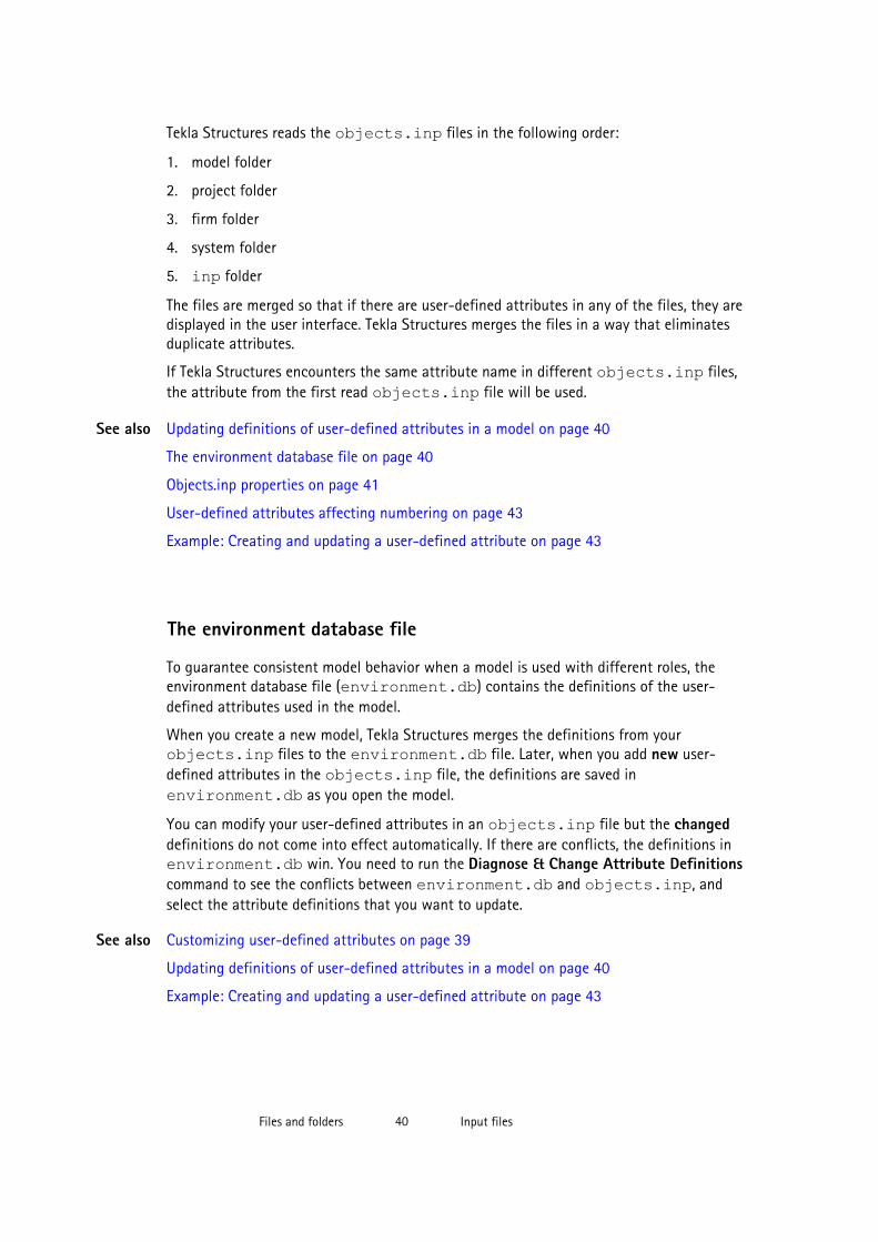
Tekla Structures reads the objects.inp files in the following order:
1. model folder
2. project folder
3. firm folder
4. system folder
5. inp folder
The files are merged so that if there are user-defined attributes in any of the files, they aredisplayed in the user interface. Tekla Structures merges the files in a way that eliminatesduplicate attributes.
If Tekla Structures encounters the same attribute name in different objects.inp files,the attribute from the first read objects.inp file will be used.
Updating definitions of user-defined attributes in a model on page 40
The environment database file on page 40
Objects.inp properties on page 41
User-defined attributes affecting numbering on page 43
Example: Creating and updating a user-defined attribute on page 43
The environment database file
To guarantee consistent model behavior when a model is used with different roles, theenvironment database file (environment.db) contains the definitions of the user-defined attributes used in the model.
When you create a new model, Tekla Structures merges the definitions from yourobjects.inp files to the environment.db file. Later, when you add new user-defined attributes in the objects.inp file, the definitions are saved inenvironment.db as you open the model.
You can modify your user-defined attributes in an objects.inp file but the changeddefinitions do not come into effect automatically. If there are conflicts, the definitions inenvironment.db win. You need to run the Diagnose & Change Attribute Definitionscommand to see the conflicts between environment.db and objects.inp, andselect the attribute definitions that you want to update.
Customizing user-defined attributes on page 39
Updating definitions of user-defined attributes in a model on page 40
Example: Creating and updating a user-defined attribute on page 43
See also
See also
Files and folders 40 Input files
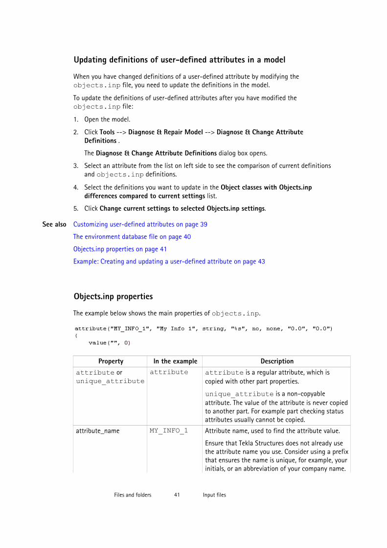
Updating definitions of user-defined attributes in a model
When you have changed definitions of a user-defined attribute by modifying theobjects.inp file, you need to update the definitions in the model.
To update the definitions of user-defined attributes after you have modified theobjects.inp file:
1. Open the model.
2. Click Tools --> Diagnose & Repair Model --> Diagnose & Change AttributeDefinitions .
The Diagnose & Change Attribute Definitions dialog box opens.
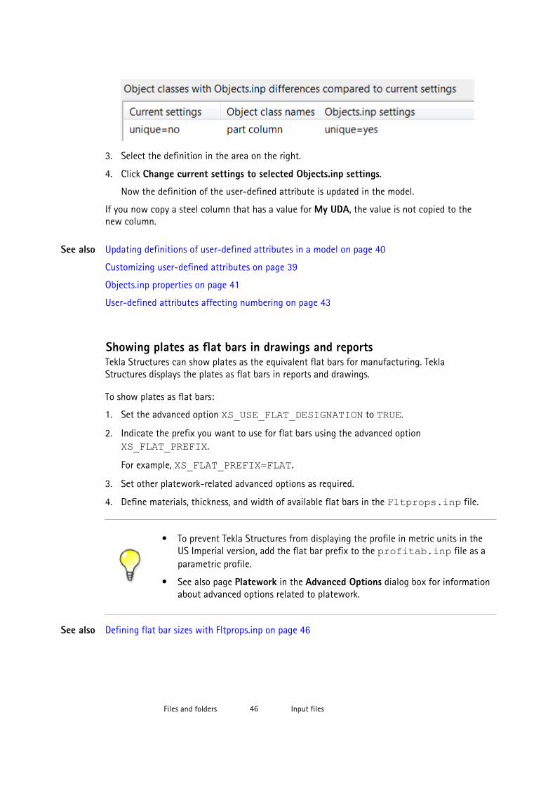
3. Select an attribute from the list on left side to see the comparison of current definitionsand objects.inp definitions.
4. Select the definitions you want to update in the Object classes with Objects.inpdifferences compared to current settings list.
5. Click Change current settings to selected Objects.inp settings.
Customizing user-defined attributes on page 39
The environment database file on page 40
Objects.inp properties on page 41
Example: Creating and updating a user-defined attribute on page 43
Objects.inp properties
The example below shows the main properties of objects.inp.
Property In the example Descriptionattribute or unique_attribute
attribute attribute is a regular attribute, which iscopied with other part properties.
unique_attribute is a non-copyableattribute. The value of the attribute is never copiedto another part. For example part checking statusattributes usually cannot be copied.
attribute_name MY_INFO_1 Attribute name, used to find the attribute value.
Ensure that Tekla Structures does not already usethe attribute name you use. Consider using a prefixthat ensures the name is unique, for example, yourinitials, or an abbreviation of your company name.
See also
Files and folders 41 Input files

Property In the example DescriptionThe attribute name is case-sensitive. Do not usespaces or reserved characters in attribute names.The maximum length of the name can be 19characters.
To include the attribute in a report or template,add the name of the attribute to your layout in theTemplate Editor. When you run a report or create adrawing, Tekla Structures displays the currentvalue of the attribute.
label_text My Info 1 Label that Tekla Structures displays in the dialogbox.
Some default attributes have prompts like j_comment, meaning that the prompt comesfrom the joints.ail message file.
value_type string integer or float for numbers
string for text
string_not_modifiable for text whosemodification is prevented. A field with the string_not_modifiable property is alwaysdisplayed as dimmed and it cannot be switched onor off. The value in the field is not saved whenclicking the Apply button or modified whenclicking the Modify button.
option for lists
date for date with small calendar
date_time_min for date and time [12:00] withsmall calendar
date_time_sec for date and time [12:00:00]with small calendar
field_format %s Definition of the field format in the dialog box
• %s for strings
• %d for numbers
special_flag no no or yesFor parts: consider in numbering
For drawings: display the attribute value indrawing list
For other elements: no effect
check_switch none noneThis option is not used.
Files and folders 42 Input files

Property In the example Descriptionattribute_value_max 0.0 0.0
This option is not used.
attribute_value_min 0.0 0.0This option is not used.
User-defined attributes affecting numbering on page 43
User-defined attributes affecting numberingYou can set whether the user-defined attribute affects numbering or not.
If you want Tekla Structures to consider the user-defined attribute when numbering, set the special_tag option to yes in the Part attributes section of objects.inp.Tekla Structures assigns different numbers to parts that are otherwise identical but havedifferent user-defined attributes.
Only user-defined attributes of parts affect numbering. User-defined attributes of otherobjects, such as phases, projects and drawings do not affect numbering.
If you want Tekla Structures to ignore the user-defined attribute when numbering, set the special_tag option to no in objects.inp.
Objects.inp properties on page 41
Example: Creating and updating a user-defined attribute
This example shows how to create your own user-defined attribute and update the model touse the changed attribute definition.
To create and update a user-defined attribute:
1. Create a new model and save it.
The user-defined attributes in the model are merged from objects.inp files andTekla Structures saves the attribute definitions in the environment.db file in themodel folder.
2. Close the model.
3. Create an input file called objects.inp in the model folder by using a standard texteditor.
4. Enter the following information in objects.inp.
See also
See also
Creating a newuser-defined
attribute
Files and folders 43 Input files
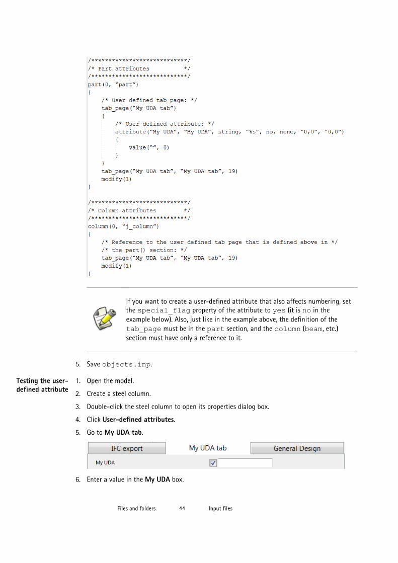
If you want to create a user-defined attribute that also affects numbering, setthe special_flag property of the attribute to yes (it is no in theexample below). Also, just like in the example above, the definition of the tab_page must be in the part section, and the column (beam, etc.)section must have only a reference to it.
5. Save objects.inp.
1. Open the model.
2. Create a steel column.
3. Double-click the steel column to open its properties dialog box.
4. Click User-defined attributes.
5. Go to My UDA tab.
6. Enter a value in the My UDA box.
Testing the user-defined attribute
Files and folders 44 Input files

7. Click Modify.
8. Copy the steel column.
9. Check the My UDA box of the new steel column.
The attribute value was also copied.
10. Close the model.
1. Open the objects.inp file in the model folder by using a standard text editor.
2. Enter unique_ before the user-defined attribute.
This makes the user-defined attribute unique, meaning that the value of the user-definedattribute will not be copied to another part.
3. Save objects.inp.
1. Open the model.
2. Enter a value in the My UDA box for a steel column and click Modify.
3. Copy the steel column.
4. Check the My UDA box of the new column.
5. The value was copied, so the user-defined attribute in the model is not unique. There is aconflict between the environment.db and objects.inp definitions.
1. Click Tools --> Diagnose & Repair Model --> Diagnose & Change AttributeDefinitions .
The Diagnose & Change Attribute Definitions dialog box opens.
2. Select My UDA in the Attribute area on the left.
You can see that My UDA is not unique in the current setting, but it is set to unique inobjects.inp.
Modifying theuser-defined
attribute
Testing theunique user-
defined attribute
Updating thedefinitions ofuser-defined
attributes
Files and folders 45 Input files
3. Select the definition in the area on the right.
4. Click Change current settings to selected Objects.inp settings.
Now the definition of the user-defined attribute is updated in the model.
If you now copy a steel column that has a value for My UDA, the value is not copied to thenew column.
Updating definitions of user-defined attributes in a model on page 40
Customizing user-defined attributes on page 39
Objects.inp properties on page 41
User-defined attributes affecting numbering on page 43
Showing plates as flat bars in drawings and reportsTekla Structures can show plates as the equivalent flat bars for manufacturing. TeklaStructures displays the plates as flat bars in reports and drawings.
To show plates as flat bars:
1. Set the advanced option XS_USE_FLAT_DESIGNATION to TRUE.
2. Indicate the prefix you want to use for flat bars using the advanced option XS_FLAT_PREFIX.
For example, XS_FLAT_PREFIX=FLAT.
3. Set other platework-related advanced options as required.
4. Define materials, thickness, and width of available flat bars in the Fltprops.inp file.
• To prevent Tekla Structures from displaying the profile in metric units in theUS Imperial version, add the flat bar prefix to the profitab.inp file as aparametric profile.
• See also page Platework in the Advanced Options dialog box for informationabout advanced options related to platework.
Defining flat bar sizes with Fltprops.inp on page 46
See also
See also
Files and folders 46 Input files

Defining flat bar sizes with Fltprops.inpUse the ..\environments\your_environment\profil\Fltprops.inp fileto define flat bar thickness, width and material.
Copy the Fltprops.inp file to a model, project or firm folder and then modify the filein the new location as required.
The first row in the file contains flat bar material definitions (enclosed in quotes " ") followedby plate thicknesses. If you do not define a material, you can use all materials for all flat bars.The following rows define the widths of available flat bars.
The units are millimeters.
Fltprops.inp contains the following data:
With the above data, Tekla Structures displays the following plates as flat bars:
Plate Material5x40, 5x45, 6x50, 6x55 All materials
8x60, 8x65, 10x70, 10x75 S235
10x100, 10x110, 15x200, 15x220 S275J0
The flat bars get the prefix that is set in the XS_FLAT_PREFIX advanced option.
Showing plates as flat bars in drawings and reports on page 46
Defining unfolding parametersThe unfolding parameters define the location of the neutral axis when a profile is unfolded.The neutral axis is a line which runs along the length of a profile where stress and strain areequal to zero. Tekla Structures uses these parameters to create NC files and to displayunfolded profiles in single-part drawings.
To define unfolding parameters, modify the unfold_corner_ratios.inp file locatedin the system folder using a standard text editor. You can copy theunfold_corner_ratios.inp file to a model, project or firm folder and then modifythe file in the new location as required. Tekla Structures searches for this file in the defaultsearch order.
Example
See also
Files and folders 47 Input files

The settings in unfold_corner_ratios.inp have no effect if the advanced option XS_USE_OLD_POLYBEAM_LENGTH_CALCULATION is set.
Folder search order on page 84
Unfolding parameter properties on page 48
Unfolding parameter properties
See below for an example of unfolding parameters in unfold_corner_ratios.inpand the descriptions of the parameters.
1 HE300A S235JR 0 180 2 0 1000 .7
Property In theexample
Description
Type 1 1 is polybeams
2 is plates modeled as polybeams (for example, PLT)
3 is for parts which are not unfolded and follow theold polybeam calculation (for example, the line 3 L** disables unfolding of L profiles)
Profile HE300A You can also use wildcards with profile, for example, HE300*.
Material S235JR You can also use wildcards with material, for example, S235*.
Rotation / thickness min 0 For polybeams: the minimum angle when the profile isrotated around its longitudinal axis
For plates: the minimum thickness of plate
Rotation / thickness max 180 For polybeams: the maximum angle when the profileis rotated around its longitudinal axis
For plates: the maximum thickness of plate
Flag 2 This property defines what kind of parts are affectedby the next two properties.
1 is sharp folds. Only polybeams with straightchamfers are affected.
2 is curved bends. Only polybeams with curvedchamfers are affected.
See also
Files and folders 48 Input files

Property In theexample
Description
Angle / radius min 0 For sharp folds: the minimum angle
For curved bends: the minimum radius
Angle / radius max 1000 For sharp folds: the maximum angle
For curved bends: the maximum radius
Ratio .7 Defines how much the profile stretches or shrinkswhen unfolded.
Ratio = (1 - the relative location of the neutral axis).
If only the inner surface of the profile shrinks, theratio is 1. If only the outer surface of the profilestretches, the ratio is 0. By default, the ratio is 0.5 forlength calculation and 0.0 for bending radiuscalculation.
Tekla Structures applies the unfolding ratio if theprofile properties are within the range indicated bythe minimum and maximum values.
To define the rotation angle, set the work plane by the first three points of thepolybeam. Set the rotation angle in the Rotation box in the Beam Propertiesdialog box.
Defining unfolding parameters on page 47
3.4 Data filesData files contain information used by certain components, for example.
These files affect the operation of components. Do not modify the files listed hereunless you are an administrator.
File Descriptionjoints.dat Contains data used in Handrailing (1024) and
Stanchions (S76) components. Used in theStanchion connection type option.
railings.dat Contains data used in Handrailing (1024).Used in the Stanchion connection type option.
See also
Files and folders 49 Data files

File Descriptionsteps.dat Contains the data for Stairs (S82) and Stairs
(S71). Used in the Step profile and Cataloguestep options.
std_flange_plates.dat Contains data for Tapered column (S99). Usedin the options:
• Outer flange profile
• Inner flange profile
• Top plate profilestd_stiffener_plates.dat Contains data used in Tapered column (S99).
Used in the Horizontal stiffener profile box.
marketsize.dat Contains available market sizes for certainmaterial grade. Can be used with fMarketSize() function in the customcomponent editor.
import_macro_data_types.dat Contains the user-defined attributes that youcan include in an input file in attribute import.
Defining flat bar sizes with Fltprops.inp on page 46
3.5 Message filesTekla Structures uses the information in the message files to display messages in the userinterface. Message files include, for example, texts used in dialog boxes.
Message files are located in the folder ..\Tekla Structures\<version>\messages (message files with the .ail extension) and in the folder ..\TeklaStructures\<version>\messages\DotAppsStrings (message files withthe .xml extension). The files include texts in languages in which the Tekla Structures userinterface is available.
Customizing message files on page 50
Example: Modifying a message file on page 51
Customizing message filesYou can customize the messages that Tekla Structures displays in the user interface.
To customize messages:
1. Do one of the following:
See also
See also
Files and folders 50 Message files

• To modify an .ail message file, go to the ..\Tekla Structures\<version>\messages folder.
• To modify an .xml message file, go to the ..\Tekla Structures\<version>\messages\DotAppsStrings folder.
2. Open the message file you want to customize using a standard text editor.
3. Modify the message as required.
4. Save the message file.
Example: Modifying a message file on page 51
Example: Modifying a message file
In this example, you will modify a message that Tekla Structures uses for near side plates indrawings. You want Tekla Structures to display (NS) instead of (N/S).
To modify the message:
1. Go to the ..\Tekla Structures\<version>\messages folder.
2. Open by_number.ail using a standard text editor.
The by_number.ail file contains both prompts and default texts that TeklaStructures uses in drawings.
3. Browse to the following section:
string by_number_msg_no_675 {...entry = ("enu", "(N/S)");};4. Change (N/S) to (NS)in the entry row.
5. Save and close the file.
Message files on page 50
3.6 Standard filesStandard files are property files that Tekla Structures uses by default.
These properties are displayed in the dialog boxes of different objects such as beams,columns or plates, when you select the standard option in the list next to the Load button,and click the Load button.
See also
See also
Files and folders 51 Standard files
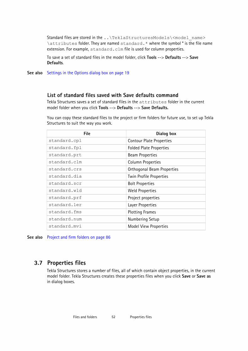
Standard files are stored in the ..\TeklaStructuresModels\<model_name>\attributes folder. They are named standard.* where the symbol * is the file nameextension. For example, standard.clm file is used for column properties.
To save a set of standard files in the model folder, click Tools --> Defaults --> SaveDefaults.
Settings in the Options dialog box on page 19
List of standard files saved with Save defaults commandTekla Structures saves a set of standard files in the attributes folder in the currentmodel folder when you click Tools --> Defaults --> Save Defaults.
You can copy these standard files to the project or firm folders for future use, to set up TeklaStructures to suit the way you work.
File Dialog boxstandard.cpl Contour Plate Properties
standard.fpl Folded Plate Properties
standard.prt Beam Properties
standard.clm Column Properties
standard.crs Orthogonal Beam Properties
standard.dia Twin Profile Properties
standard.scr Bolt Properties
standard.wld Weld Properties
standard.prf Project properties
standard.ler Layer Properties
standard.fms Plotting Frames
standard.num Numbering Setup
standard.mvi Model View Properties
Project and firm folders on page 86
3.7 Properties filesTekla Structures stores a number of files, all of which contain object properties, in the currentmodel folder. Tekla Structures creates these properties files when you click Save or Save asin dialog boxes.
See also
See also
Files and folders 52 Properties files
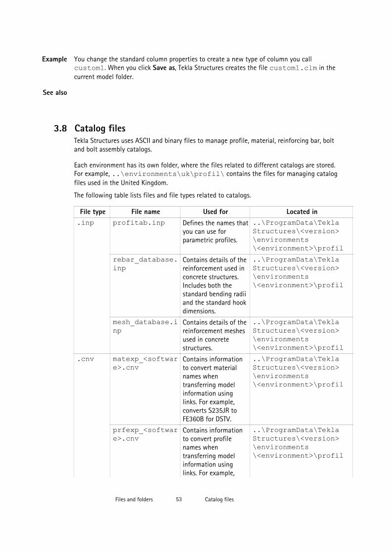
You change the standard column properties to create a new type of column you callcustom1. When you click Save as, Tekla Structures creates the file custom1.clm in thecurrent model folder.
3.8 Catalog filesTekla Structures uses ASCII and binary files to manage profile, material, reinforcing bar, boltand bolt assembly catalogs.
Each environment has its own folder, where the files related to different catalogs are stored.For example, ..\environments\uk\profil\ contains the files for managing catalogfiles used in the United Kingdom.
The following table lists files and file types related to catalogs.
File type File name Used for Located in.inp profitab.inp Defines the names that
you can use forparametric profiles.
..\ProgramData\TeklaStructures\<version>\environments\<environment>\profil
rebar_database.inp
Contains details of thereinforcement used inconcrete structures.Includes both thestandard bending radiiand the standard hookdimensions.
..\ProgramData\TeklaStructures\<version>\environments\<environment>\profil
mesh_database.inp
Contains details of thereinforcement meshesused in concretestructures.
..\ProgramData\TeklaStructures\<version>\environments\<environment>\profil
.cnv matexp_<software>.cnv
Contains informationto convert materialnames whentransferring modelinformation usinglinks. For example,converts S235JR toFE360B for DSTV.
..\ProgramData\TeklaStructures\<version>\environments\<environment>\profil
prfexp_<software>.cnv
Contains informationto convert profilenames whentransferring modelinformation usinglinks. For example,
..\ProgramData\TeklaStructures\<version>\environments\<environment>\profil
Example
See also
Files and folders 53 Catalog files

File type File name Used for Located inconverts convertsHEA100 to HE100A forDSTV.
.clb For example,RU_CF.clb
Contains thedefinitions ofparametric profilesused inprofitab.inp.
..\ProgramData\TeklaStructures\<version>\environments\common\inp
.lis You can define the filename while exporting.
Created when youexport bolt, profile andmaterial catalogs.
You can define the folder where toexport the files.
.db assdb.db The bolt assemblycatalog.
..\ProgramData\TeklaStructures\<version>\environments\<environment>\profil
screwdb.db The bolt catalog. ..\ProgramData\TeklaStructures\<version>\environments\<environment>\profil
.bin profdb.bin The profile catalog. ..\ProgramData\TeklaStructures\<version>\environments\<environment>\profil
matdb.bin The material catalog. ..\ProgramData\TeklaStructures\<version>\environments\<environment>\profil
3.9 Font filesYou can define the location of font files with the advanced option DXK_FONTPATH in theteklastructures.ini or your environment initialization file. For example, you can usefonts available in the folder ..\ProgramData\Tekla Structures\<version>\environments\common\fonts. This folder includes the following fonts:
Font Font typefixfont.fon Tekla Structures graphic font
romco.fon Tekla Structures graphic font
romsim.fon Tekla Structures graphic font
romsim8.fon Tekla Structures graphic font
See also
Files and folders 54 Font files
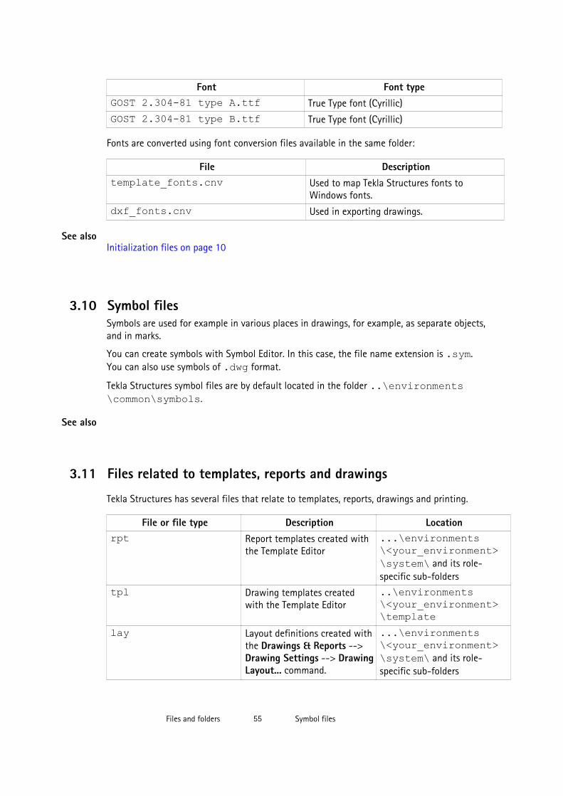
Font Font typeGOST 2.304-81 type A.ttf True Type font (Cyrillic)
GOST 2.304-81 type B.ttf True Type font (Cyrillic)
Fonts are converted using font conversion files available in the same folder:
File Descriptiontemplate_fonts.cnv Used to map Tekla Structures fonts to
Windows fonts.
dxf_fonts.cnv Used in exporting drawings.
Initialization files on page 10
3.10 Symbol filesSymbols are used for example in various places in drawings, for example, as separate objects,and in marks.
You can create symbols with Symbol Editor. In this case, the file name extension is .sym.You can also use symbols of .dwg format.
Tekla Structures symbol files are by default located in the folder ..\environments\common\symbols.
3.11 Files related to templates, reports and drawings
Tekla Structures has several files that relate to templates, reports, drawings and printing.
File or file type Description Locationrpt Report templates created with
the Template Editor...\environments\<your_environment>\system\ and its role-specific sub-folders
tpl Drawing templates createdwith the Template Editor
..\environments\<your_environment>\template
lay Layout definitions created withthe Drawings & Reports -->Drawing Settings --> DrawingLayout... command.
...\environments\<your_environment>\system\ and its role-specific sub-folders
See also
See also
Files and folders 55 Symbol files

File or file type Description Locationplotdev.bin Printer device definitions
created with the File -->Print... --> Printer Catalog...command.
..\environments\<your_environment\system
xdproc Master Drawing Catalog ruleset
...\environments\<your_environment>\system\ and its role-specific sub-folders
xdproc.master Master Drawing Catalogmaster drawing file
...\environments\<your_environment>\system\ and its role-specific sub-folders
xdproc.master.png Master Drawing Catalogsample (preview) image files
...\environments\<your_environment>\system\ and its role-specific sub-folders
xdproc.png Master Drawing Catalogthumbnail image files
...\environments\<your_environment>\system\ and its role-specific sub-folders
3.12 Image filesTekla Structures uses image files in several places:
• In templates in drawings
• In drawing snapshots
• In component dialog boxes and thumbnails
• In drawing line types
• In the surface treatment dialog box
• In the Master Drawing Catalog for thumbnails and sample images
• In profile properties dialog boxes
The following image file formats are supported in Tekla Structures:
• In templates: bmp, gif, grd, jpg, ppm, pgm, rle, tiff and xkrl• In drawing snapshots, and int thumbnail and sample images for the Master Drawing
Catalog: png• Other situations: bmp
See also
Files and folders 56 Image files
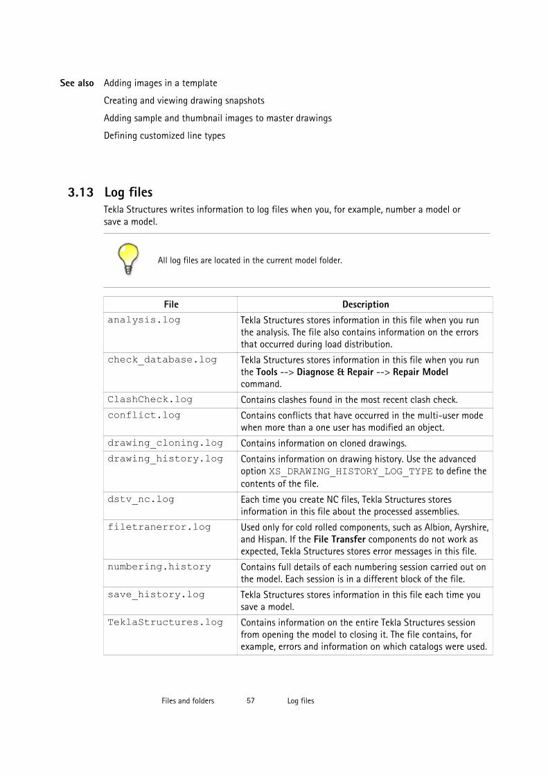
Adding images in a template
Creating and viewing drawing snapshots
Adding sample and thumbnail images to master drawings
Defining customized line types
3.13 Log filesTekla Structures writes information to log files when you, for example, number a model orsave a model.
All log files are located in the current model folder.
File Descriptionanalysis.log Tekla Structures stores information in this file when you run
the analysis. The file also contains information on the errorsthat occurred during load distribution.
check_database.log Tekla Structures stores information in this file when you runthe Tools --> Diagnose & Repair --> Repair Modelcommand.
ClashCheck.log Contains clashes found in the most recent clash check.
conflict.log Contains conflicts that have occurred in the multi-user modewhen more than a one user has modified an object.
drawing_cloning.log Contains information on cloned drawings.
drawing_history.log Contains information on drawing history. Use the advancedoption XS_DRAWING_HISTORY_LOG_TYPE to define thecontents of the file.
dstv_nc.log Each time you create NC files, Tekla Structures storesinformation in this file about the processed assemblies.
filetranerror.log Used only for cold rolled components, such as Albion, Ayrshire,and Hispan. If the File Transfer components do not work asexpected, Tekla Structures stores error messages in this file.
numbering.history Contains full details of each numbering session carried out onthe model. Each session is in a different block of the file.
save_history.log Tekla Structures stores information in this file each time yousave a model.
TeklaStructures.log Contains information on the entire Tekla Structures sessionfrom opening the model to closing it. The file contains, forexample, errors and information on which catalogs were used.
See also
Files and folders 57 Log files

File Descriptionwizard.log Tekla Structures stores information in this file when you run a
drawing rule set (wizard) file. The file contains, for example,errors and number of drawings created.
Viewing a log file on page 58
XS_DRAWING_HISTORY_LOG_TYPE
XS_CNC_CUT_PLANE_HEIGHT
XS_LOG_FILE_NAME
Viewing a log file
To view a log file:
1. Open the model whose log history you want view.
2. Click Tools --> Display Log File and select a log file you want to examine.
The options are:
• Session history log (TeklaStructures.log)
• Numbering history log (numbering.history)
• Drawing history log (drawing_history.log)
• Saving history log (save_history.log)
• Clash Check history log (ClashCheck.log)
• Analysis history log (analysis.log)
If you want to view the log files in a viewer that has been associated with the file type, forexample, in Microsoft Notepad, select Tools --> Display Log File --> With AssociatedViewer .
Alternatively, if you want to view the log files on a toolbar at the bottom of the TeklaStructures window, select Tools --> Toolbars --> Message Panel .
Log files on page 57
The numbering.history log file on page 59
See also
See also
Files and folders 58 Log files

Viewing parts listed in a log fileThe parts that are listed in a log file can be viewed in the model.
To view parts listed in a log file:
1. Click Tools --> Display Log File .
2. Select a log file you want to examine.
3. In the log file, select a row which contains a part or an assembly.
Parts and assemblies have the prefix id.
Tekla Structures highlights the part in the model.
If there are several parts or assemblies on a row and you select that row, Tekla Structureshighlights all the parts in the model. You can also select parts on different rows.
You can access a part’s or an assembly’s pop-up menu from the log file by right-clicking arow that contains a part or an assembly. Tekla Structures displays the same pop-up menuas when you right-click a part or an assembly in the model.
Log files on page 57
The numbering.history log fileThe numbering.history log file contains full details of each numbering session carriedout on the model. Each numbering session is in a different block of the file.
If you remove or delete the numbering.history log file, Tekla Structures generates anew file with the same name next time when you run numbering. The new file does notcontain a history of previous numbering sessions.
Below is an example of the contents of a numbering.history log file.
User name, date and time of the numbering.
See also
Example
Files and folders 59 Log files

Numbering method.
• Modified numbering is displayed when you run the Number Modified Objectscommand.
• Modified numbering for selected series is displayed when you runthe Number Series of Selected Objects command.
• Diagnose & Repair Numbering: All is displayed when you run theDiagnose & Repair Numbering: All command.
• Diagnose & Repair Numbering: Series of selected objectsis displayed when you run the Diagnose & Repair Numbering: Series of SelectedObjects command.
• Renumber all is displayed when you select the Renumber all option in theNumbering Setup dialog box.
Some Compare options set in the Numbering Setup dialog box are displayed in thenumbering.history log file only if they are set differently than the default value:
• Compare modified to old parts• Compare new to old part• No holes comparing• No part name comparing• Beam orientation• Column orientationSome Compare options are not displayed at all:
• Reinforcing bars
• Embedded objects
• Surface treatmentNumbering options.
• Use old numbers is displayed only when you have selected the Re-use oldnumbers option in the Numbering Setup dialog box.
• Check for standard parts is displayed only when you have selected theCheck for standard parts option in the Numbering Setup dialog box.
Tolerances are set in the Numbering Setup dialog box.
Changes in the position numbers and in the numbering series during one numberingsession.
In addition:
If a numbering series overlaps another, the errors are written to the log file.
Numbering series in the numbering.history log file on page 61See also
Files and folders 60 Log files

Viewing parts listed in a log file on page 58
Numbering series in the numbering.history log fileTekla Structures lists information on the numbered parts and assemblies in thenumbering.history log file.
The numbering.history log after one concrete beam B/20 has been created andnumbered:
Part position number.
• The part with the GUID ID510F595D-0000-0030-3133-353939383335 is apart of the numbering series Concrete_B-20/1.
• The part becomes the first part in the numbering series: Concrete_B-20/0 ->Concrete_B-20/1.
Assembly position number.
• The assembly ID of the part is ID510F595D-0000-002F-3133-353939383335.
• The part belongs to the B/20 assembly numbering series, which is also the cast unitnumbering series.
• The part gets the assembly position number: B/20: B/0 -> B/20.
The numbering.history log after another concrete beam B/21 has been created andnumbered:
Example 1
Example 2
Files and folders 61 Log files

Part position number of the new part.
• The part with the ID ID510F595D-0000-0030-3133-353939383335 ispart of the numbering series Concrete_B-20/1.
• The part becomes the second part in the numbering series: Concrete_B-20/0 -> Concrete_B-20/2.
Assembly position number.
• The assembly ID of the part is ID510F595D-0000-002F-3133-353939383335.
• The part belongs to the B/20 assembly numbering series, which is also the cast unitnumbering series.
• The part gets the assembly position number: B/20 B/0 -> B/21.
The numbering.history log file on page 59
Viewing parts listed in a log file on page 58
3.14 Model folder files and file name extensions
The following table lists the files and file name extensions in use in Tekla Structures andlocated in model folder.
File or filename
extension
Description For moreinformation
Files in the Tekla Structures model folder:*.db1 The model database
*.db2 Numbering database
environment.db
Database for user-defined attribute definitions
See also
Files and folders 62 Model folder files and file name extensions

File or filename
extension
Description For moreinformation
xslib.db1 Contains information on user-defined connections anddetails, and default component descriptions.
*.idrm Mapping file, which handles IDs. Do not modify.
xslib.db2 Contains numbering information. Numbering themodel
options_model.db andoptions_drawings.db
Contain values for model-specific options from theOptions dialog box and values for model-specificadvanced options from the Advanced Options dialogbox. When a model is created, Tekla Structures readsmodel-specific options and advanced options valuesfrom the standard.opt file and .ini files in theenvironment folders and saves them in these twodatabases.
Settings in theOptions dialogbox on page 19
xsdb.xs File used for displaying the name of the model in theOpen dialog box.
Opening a model
xs_user.<user name>
Contains interface settings specified by the user.
Each time a model is saved, anxs_user.<user_name> file is created or updated.These settings are user specific. If thexs_user.<user_name> settings are not found inthe model folder when you open the model, TeklaStructures searches for the xs_user.default filefrom the following path: model, model/attributes,project, firm, system. If this file is not found, TeklaStructures default settings will be used.
The file contains settings for many of the switches onthe Tools --> Options menu and the settings for theicons on the Selecting and Snapping toolbars.
save_history.log
Tekla Structures stores the information in this file eachtime the model is saved. The file includes the savingtime, date and information on any conflicts duringsaving.
Saving a model
notification_report.xsr
File used for displaying a notification report ofassignments when you open a model.
XS_SHOW_NOTIFICATION_REPORT
TeklaStructuresModel.xml
Contains information on the Tekla Structures session,for example on opening, closing and what catalogs arebeing used.
dotlog.txt A log file that contains information on Tekla Open APIapplication use.
Tekla Open APIon page 8
Files and folders 63 Model folder files and file name extensions
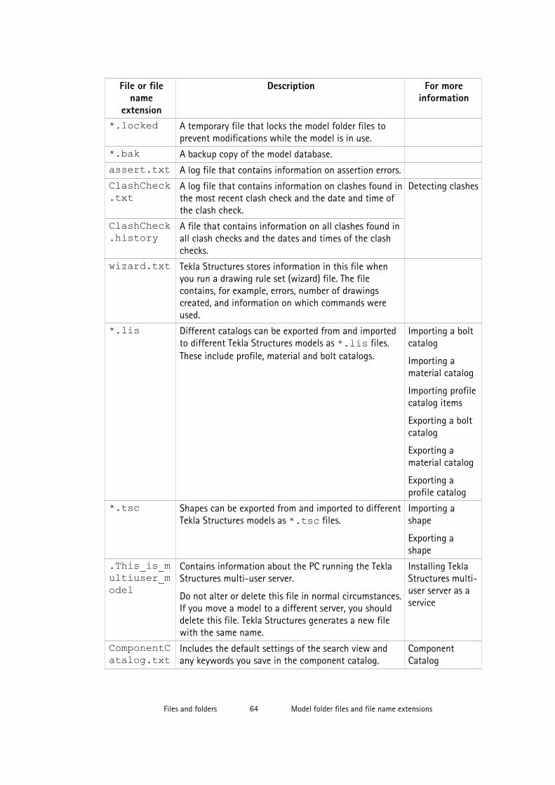
File or filename
extension
Description For moreinformation
*.locked A temporary file that locks the model folder files toprevent modifications while the model is in use.
*.bak A backup copy of the model database.
assert.txt A log file that contains information on assertion errors.
ClashCheck.txt
A log file that contains information on clashes found inthe most recent clash check and the date and time ofthe clash check.
Detecting clashes
ClashCheck.history
A file that contains information on all clashes found inall clash checks and the dates and times of the clashchecks.
wizard.txt Tekla Structures stores information in this file whenyou run a drawing rule set (wizard) file. The filecontains, for example, errors, number of drawingscreated, and information on which commands wereused.
*.lis Different catalogs can be exported from and importedto different Tekla Structures models as *.lis files.These include profile, material and bolt catalogs.
Importing a boltcatalog
Importing amaterial catalog
Importing profilecatalog items
Exporting a boltcatalog
Exporting amaterial catalog
Exporting aprofile catalog
*.tsc Shapes can be exported from and imported to differentTekla Structures models as *.tsc files.
Importing ashape
Exporting ashape
.This_is_multiuser_model
Contains information about the PC running the TeklaStructures multi-user server.
Do not alter or delete this file in normal circumstances.If you move a model to a different server, you shoulddelete this file. Tekla Structures generates a new filewith the same name.
Installing TeklaStructures multi-user server as aservice
ComponentCatalog.txt
Includes the default settings of the search view andany keywords you save in the component catalog.
ComponentCatalog
Files and folders 64 Model folder files and file name extensions

File or filename
extension
Description For moreinformation
ModelBasicsComponents.txt
Lists the basic components available. ComponentCatalog
Worktypes.xml
Lists available task types. Created when you start theTask Manager.
Defining a tasktype
WorkTypeProperties.xml
Lists allowed property types and their units.
.tmp A file used to store temporary data.
.cnv A file used to map Tekla Structures profile and materialnames with names used in other software.
Conversion files
Files in the analysis model folder:*.ifc The analysis model exported in IFC format. Analysis model
properties
*.stp The analysis model exported in CIS/2 format.
*.map A file used for debugging analysis models.
analysis_results.db5
Database for analysis load combination results. Saving analysisresults
*.db6 Analysis model database. Analysis modelproperties
Files in the \screenshots folder:*.png Screenshot taken in Tekla Structures. Taking a
screenshot
Files in the \attributes folder:*.rop Reference object user-defined attribute properties Reference model
objects*.rop.more Reference object properties
*.m10000017
Fabtrol XML import properties Fabtrol XML
*.m10000015
Import attribute properties Attribute import
*.ncf NC file properties NC files
*.ExportIFC.MainDialog
IFC export properties IFC export
*.m440000004
3D DWG/DXF export properties DWG and DXF
*.m440000003
3D DGN export properties Exporting to 3DDGN files
Files and folders 65 Model folder files and file name extensions

File or filename
extension
Description For moreinformation
*.m1000004 FEM export properties FEM
*.m10000011
CIS analysis model export properties CIS and CIMSteel
*.m10000026
CIS manufacturing model export properties CIS and CIMSteel
*.m1000007 CAD export properties Exporting to CAD
*.m10000016
Cover sheet export properties
*.SObjGrp Object group selection filter properties Filtering objectsusing a selectionfilter
*.grd Grid properties Grid properties
*.grd.more Grid user-defined attribute properties
*.grdp Grid line properties Grid lineproperties*.grdp.mor
eGrid line user-defined attribute properties
*.mvi Model view properties that you have saved for themodel.
Default 3D, part, component, custom component,assembly, and cast unit view settings files need to besaved with names used in common environment:
3D view: basic_view
3D part view: part_basic_view
Part front view: part_front_view
Part top view: part_top_view
Part end view: part_end_view
Part perspective view: part_persp_view
3D component view: joint_basic_view
Component front view: joint_front_view
Component top view: joint_top_view
Component end view: joint_end_view
Component perspective view: joint_persp_view
Custom component front view:custom_object_editor_front_view
Custom component top view:custom_object_editor_top_view
View properties
Files and folders 66 Model folder files and file name extensions

File or filename
extension
Description For moreinformation
Custom component end view:custom_object_editor_end_view
Custom component perspective view:custom_object_editor_perspective_view
3D assembly or cast unit view: assembly_basic_view
Assembly or cast unit front view: assembly_front_view
Assembly or cast unit top view: assembly_top_view
Assembly or cast unit end view: assembly_end_view
Assembly or cast unit back view: assembly_back_view
Assembly or cast unit bottom view:assembly_bottom_view
Assembly or cast unit perspective view:assebly_persp_view
*.gvi Saved properties for creating views along grid lines Grid viewproperties
*.rep Object representation properties Changing thecolor andtransparency ofparts
*.clm Steel column properties Steel columnproperties*.clm.more Steel column user-defined attribute properties
*.prt Steel beam properties Steel beamproperties*.prt.more Steel beam user-defined attribute properties
*.crs Orthogonal beam properties Orthogonal beamproperties*.crs.more Orthogonal beam user-defined attribute properties
*.dia Twin profile properties Twin profileproperties*.dia.more Twin profile user-defined attribute properties
*.cpl Contour plate properties Contour plateproperties*.cpl.more Contour plate user-defined attribute properties
*.ips Item properties Item properties
*.ips.more Item user-defined attribute properties
*.cpf Pad footing properties Pad footingproperties*.cpf.more Pad footing user-defined attribute properties
*.csf Strip footing properties Strip footingproperties*.csf.more Strip footing user-defined attribute properties
Files and folders 67 Model folder files and file name extensions

File or filename
extension
Description For moreinformation
*.ccl Concrete column properties Concrete columnproperties*.ccl.more Concrete column user-defined attribute properties
.*.cbm Concrete beam or concrete polybeam properties Concrete beamproperties*.cbm.more Concrete beam or concrete polybeam user-defined
attribute properties
*.csl Concrete slab properties Concrete slabproperties*.csl.more Concrete slab user-defined attribute properties
*.cpn Concrete panel properties Concrete panelproperties*.cpn.more Concrete panel user-defined attribute properties
*.ipc Concrete item properties Concrete itemproperties*.ipc.more Concrete item user-defined attribute properties
*.rbr Reinforcing bar properties Creating areinforcing bar*.rbr.more Reinforcing bar user-defined attribute properties
*.rbg Reinforcing bar group properties Creating areinforcing bargroup
*.rbg.more Reinforcing bar group user-defined attribute properties
*.rcu Curved reinforcing bar group properties Creating a curvedreinforcing bargroup
*.rci Circular reinforcing bar group properties Creating acircularreinforcing bargroup
*.rbm Reinforcement mesh properties Creating arectangularreinforcementmesh
*.rbm.more Reinforcement mesh user-defined attribute properties
*.rbs Reinforcement strand pattern properties Creating areinforcementstrand pattern
*.rbs.more Reinforcement strand pattern user-defined attributeproperties
*.rsp Reinforcement splice properties Creating areinforcementsplice
*.rsp.more Reinforcement splice user-defined attribute properties
*.admodel Analysis model properties Analysis modelproperties*.admodel.
moreAnalysis model user-defined attribute properties
*.lm1 Point load properties Point loadproperties
Files and folders 68 Model folder files and file name extensions
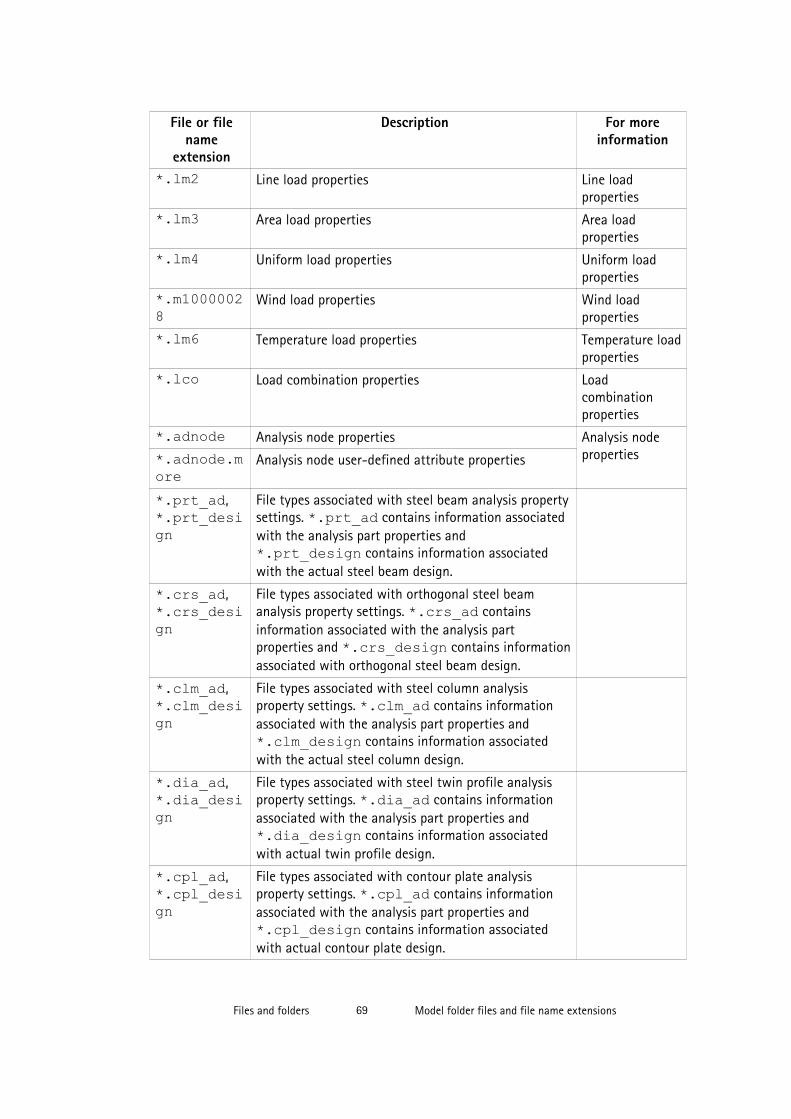
File or filename
extension
Description For moreinformation
*.lm2 Line load properties Line loadproperties
*.lm3 Area load properties Area loadproperties
*.lm4 Uniform load properties Uniform loadproperties
*.m10000028
Wind load properties Wind loadproperties
*.lm6 Temperature load properties Temperature loadproperties
*.lco Load combination properties Loadcombinationproperties
*.adnode Analysis node properties Analysis nodeproperties*.adnode.m
oreAnalysis node user-defined attribute properties
*.prt_ad,*.prt_design
File types associated with steel beam analysis propertysettings. *.prt_ad contains information associatedwith the analysis part properties and*.prt_design contains information associatedwith the actual steel beam design.
*.crs_ad,*.crs_design
File types associated with orthogonal steel beamanalysis property settings. *.crs_ad containsinformation associated with the analysis partproperties and *.crs_design contains informationassociated with orthogonal steel beam design.
*.clm_ad,*.clm_design
File types associated with steel column analysisproperty settings. *.clm_ad contains informationassociated with the analysis part properties and*.clm_design contains information associatedwith the actual steel column design.
*.dia_ad,*.dia_design
File types associated with steel twin profile analysisproperty settings. *.dia_ad contains informationassociated with the analysis part properties and*.dia_design contains information associatedwith actual twin profile design.
*.cpl_ad,*.cpl_design
File types associated with contour plate analysisproperty settings. *.cpl_ad contains informationassociated with the analysis part properties and*.cpl_design contains information associatedwith actual contour plate design.
Files and folders 69 Model folder files and file name extensions

File or filename
extension
Description For moreinformation
*.cpf_ad,*.cpf_design
File types associated with pad footing analysis propertysettings. *.cpf_ad contains information associatedwith the analysis part properties and*.cpf_design contains information associatedwith the actual pad footing design.
*.csf_ad,*.csf_design
File types associated with strip footing analysisproperty settings. *.csf_ad contains informationassociated with the analysis part properties and*.csf_design contains information associatedwith the actual strip footing design.
*.ccl_ad,*.ccl_design
File types associated with concrete column analysisproperty settings. *.ccl_ad contains informationassociated with the analysis part properties and*.ccl_design contains information associatedwith the actual concrete column design.
*.cbm_ad,*.cbm_design
File types associated with concrete beam analysisproperty settings. *.cbm_ad contains informationassociated with the analysis part properties and*.cbm_design contains information associatedwith the actual concrete beam design.
*.csl_ad,*.csl_design
File types associated with concrete slab analysisproperty settings. *.csl_ad contains informationassociated with the analysis part properties and*.csl_design contains information associatedwith the actual slab design.
*.cpn_ad,*.cpn_design
File types associated with concrete panel analysisproperty settings. *.cpl_ad contains informationassociated with the analysis part properties and*.cpl_design contains information associatedwith the actual concrete panel design.
*.srf Surface treatment properties Adding surfacetreatment*.srf.more User-defined surface treatment attribute properties
*.cha Edge chamfer properties Edge chamferproperties*.cha.more User-defined edge chamfer attribute properties
.scr Bolt properties Bolt properties
.scr.more User-defined bolt attribute properties
*.wld Weld properties Weld properties
*.wld.more User-defined weld attribute properties
*.m1000009 Control number properties Control numbersettings
Files and folders 70 Model folder files and file name extensions

File or filename
extension
Description For moreinformation
*.m1000010 Control number locking properties Locking andunlocking controlnumbers
*.num Numbering setup properties Generalnumberingsettings
*.rpr Report properties Report settings
*.4d Project status visualization properties Project StatusVisualization
standard.opt
Settings are saved in standard.opt in the\attributes folder only when you save your ownsettings in the Options dialog box using Save.
There is a standard.opt file in the environmentfolder that gives the initial values to be loaded when amodel is created.
Settings in theOptions dialogbox on page 19
ComponentCatalogTreeView.txt
Includes the default settings of the folder view in thecomponent catalog.
Groupingcomponents inthe ComponentCatalog
Files in the \PublicWeb folder:Model.xml Web Viewer model in XML format Tekla Web Viewer
index.html Index file for the Web Viewer model
Model.zsol Contains information on solid objects in the WebViewer model
Files in the cssfolder
Contains Cascading Style Sheet (CSS) files for the WebViewer Model
Files in the dllfolder
Contains dynamic link libraries (DLL) files for the WebViewer model
Files in thehelp folder
Contains Web Viewer help and css files.
Files in theimages folder
Contains image files used in Web Viewer
Files in the \drawings folder:*.dg Drawing files Saving drawings
About drawingfiles
*.ldb Drawing export layer properties
Common drawing files:
Files and folders 71 Model folder files and file name extensions

File or filename
extension
Description For moreinformation
*.ldr Drawing link properties Adding links toother drawings
*.cs Section symbol properties Creating asection view
*.detail Detail symbol properties Creating a detailview
*.fas Text file properties Adding links totext files
*.fhl Hyperlink properties Adding hyperlinks
Files related to single-part drawings, drawing level properties, saved in \attributesfolder:*.wd Single-part drawing properties Drawing
properties*.wd.copt Single-part drawing detailed object level settings
*.wd.more Single-part drawing user-defined attributes
*.wdf Single-part drawing filter properties Filtering indrawings*.wdnf Single-part drawing neighbor part filter properties
*.wdl Single-part drawing layout properties Drawing layout
*.wdl.more Single-part drawing user-defined layout attributes
*.wdv Single-part drawing view properties View propertiesin drawings*.wdv.more Single-part drawing user-defined view attributes
*.wdc Single-part drawing section view properties Section viewproperties*.wdc.more Single-part drawing user-defined section view
attributes
*.wdd Single-part drawing dimension properties Dimension anddimensioningproperties
*.wdd.more Single-part drawing user-defined dimension attributes
*.wdcd Single-part drawing dimensioning properties
*.wdcdmore
Single-part drawing user-defined dimensioningattributes
*.wpm Single-part drawing part mark properties Part markelements
*.wsm Single-part drawing bolt mark properties Bolt markelements
*.wnpm Single-part drawing neighbor part mark properties Part markelements
*.wdsurfm Single-part drawing surface treatment mark properties Surfacetreatment markelements
*.wdsurfm.more
Single-part drawing user-defined surface treatmentmark attributes
Files and folders 72 Model folder files and file name extensions
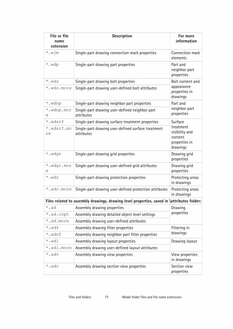
File or filename
extension
Description For moreinformation
*.wjm Single-part drawing connection mark properties Connection markelements
*.wdp Single-part drawing part properties Part andneighbor partproperties
*.wds Single-part drawing bolt properties Bolt content andappearanceproperties indrawings
*.wds.more Single-part drawing user-defined bolt attributes
*.wdnp Single-part drawing neighbor part properties Part andneighbor partproperties
*.wdnp.more
Single-part drawing user-defined neighbor partattributes
*.wdsrf Single-part drawing surface treatment properties Surfacetreatmentvisibility andcontentproperties indrawings
*.wdsrf.more
Single-part drawing user-defined surface treatmentattributes
*.wdgr Single-part drawing grid properties Drawing gridproperties
*.wdgr.more
Single-part drawing user-defined grid attributes Drawing gridproperties
*.wdr Single-part drawing protection properties Protecting areasin drawings
*.wdr.more Single-part drawing user-defined protection attributes Protecting areasin drawings
Files related to assembly drawings, drawing level properties, saved in \attributes folder:*.ad Assembly drawing properties Drawing
properties*.ad.copt Assembly drawing detailed object level settings
*.ad.more Assembly drawing user-defined attributes
*.adf Assembly drawing filter properties Filtering indrawings*.adnf Assembly drawing neighbor part filter properties
*.adl Assembly drawing layout properties Drawing layout
*.adl.more Assembly drawing user-defined layout attributes
*.adv Assembly drawing view properties View propertiesin drawings
*.adc Assembly drawing section view properties Section viewproperties
Files and folders 73 Model folder files and file name extensions

File or filename
extension
Description For moreinformation
*.add Assembly drawing dimension properties Dimension anddimensioningproperties
*.add.more Assembly drawing user-defined dimension attributes
*.adcd Assembly drawing dimensioning properties
*.adcd.more
Assembly drawing user-defined dimensioningattributes
*.apm Assembly drawing part mark properties Part markelements
*.asm Assembly drawing bolt mark properties Bolt markelements
*.anpm Assembly drawing neighbor part mark properties Part markelements
*.adsurfm Assembly drawing surface treatment mark properties Surfacetreatment markelements
*.adsurfm.more
Assembly drawing user-defined surface treatmentmark attributes
*.ajm Assembly drawing connection mark properties Connection markelements
*.adp Assembly drawing part properties Part andneighbor partproperties
*.adp.more Assembly drawing user-defined part attributes
*.ads Assembly drawing bolt properties Bolt content andappearanceproperties indrawings
*.adnp Assembly drawing neighbor part properties Part andneighbor partproperties
*.adnp.more
Assembly drawing user-defined neighbor partattributes
*.adsrf Assembly drawing surface treatment properties Surfacetreatmentvisibility andcontentproperties indrawings
*.adsrf.more
Assembly drawing user-defined surface treatmentattributes
*.adw Assembly drawing welding properties Model weld markvisibility andappearanceproperties indrawings
*.adw.more Assembly drawing user-defined welding attributes
*.adgr Assembly drawing grid properties Drawing gridproperties
Files and folders 74 Model folder files and file name extensions
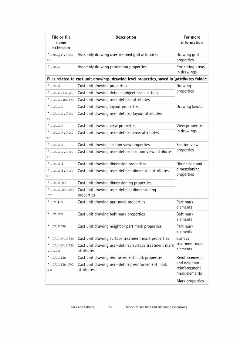
File or filename
extension
Description For moreinformation
*.adgr.more
Assembly drawing user-defined grid attributes Drawing gridproperties
*.adr Assembly drawing protection properties Protecting areasin drawings
Files related to cast unit drawings, drawing level properties, saved in \attributes folder:*.cud Cast unit drawing properties Drawing
properties*.cud.copt Cast unit drawing detailed object level settings
*.cud.more Cast unit drawing user-defined attributes
*.cudl Cast unit drawing layout properties Drawing layout
*.cudl.more
Cast unit drawing user-defined layout attributes
*.cudv Cast unit drawing view properties View propertiesin drawings*.cudv.mor
eCast unit drawing user-defined view attributes
*.cudc Cast unit drawing section view properties Section viewproperties*.cudc.mor
eCast unit drawing user-defined section view attributes
*.cudd Cast unit drawing dimension properties Dimension anddimensioningproperties
*.cudd.more
Cast unit drawing user-defined dimension attributes
*.cudcd Cast unit drawing dimensioning properties
*.cudcd.more
Cast unit drawing user-defined dimensioningproperties
*.cupm Cast unit drawing part mark properties Part markelements
*.cusm Cast unit drawing bolt mark properties Bolt markelements
*.cunpm Cast unit drawing neighbor part mark properties Part markelements
*.cudsurfm Cast unit drawing surface treatment mark properties Surfacetreatment markelements
*.cudsurfm.more
Cast unit drawing user-defined surface treatment markattributes
*.cudrm Cast unit drawing reinforcement mark properties Reinforcementand neighborreinforcementmark elements
Mark properties
*.cudrm.more
Cast unit drawing user-defined reinforcement markattributes
Files and folders 75 Model folder files and file name extensions
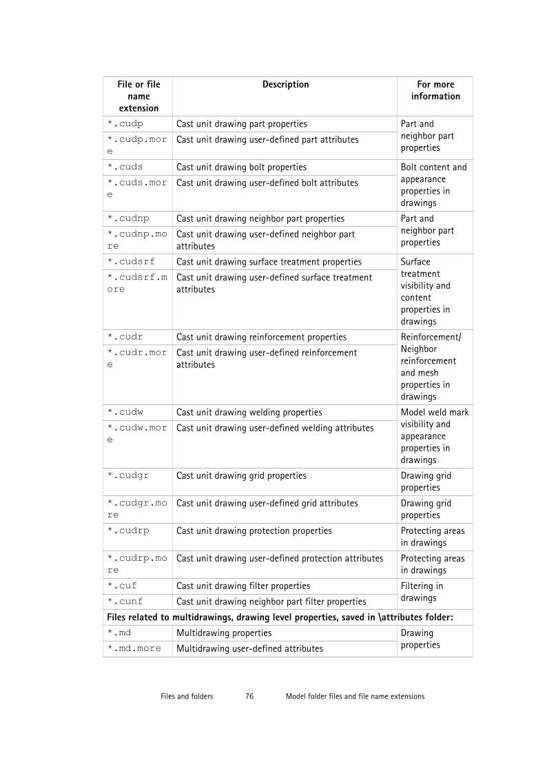
File or filename
extension
Description For moreinformation
*.cudp Cast unit drawing part properties Part andneighbor partproperties
*.cudp.more
Cast unit drawing user-defined part attributes
*.cuds Cast unit drawing bolt properties Bolt content andappearanceproperties indrawings
*.cuds.more
Cast unit drawing user-defined bolt attributes
*.cudnp Cast unit drawing neighbor part properties Part andneighbor partproperties
*.cudnp.more
Cast unit drawing user-defined neighbor partattributes
*.cudsrf Cast unit drawing surface treatment properties Surfacetreatmentvisibility andcontentproperties indrawings
*.cudsrf.more
Cast unit drawing user-defined surface treatmentattributes
*.cudr Cast unit drawing reinforcement properties Reinforcement/Neighborreinforcementand meshproperties indrawings
*.cudr.more
Cast unit drawing user-defined reinforcementattributes
*.cudw Cast unit drawing welding properties Model weld markvisibility andappearanceproperties indrawings
*.cudw.more
Cast unit drawing user-defined welding attributes
*.cudgr Cast unit drawing grid properties Drawing gridproperties
*.cudgr.more
Cast unit drawing user-defined grid attributes Drawing gridproperties
*.cudrp Cast unit drawing protection properties Protecting areasin drawings
*.cudrp.more
Cast unit drawing user-defined protection attributes Protecting areasin drawings
*.cuf Cast unit drawing filter properties Filtering indrawings*.cunf Cast unit drawing neighbor part filter properties
Files related to multidrawings, drawing level properties, saved in \attributes folder:*.md Multidrawing properties Drawing
properties*.md.more Multidrawing user-defined attributes
Files and folders 76 Model folder files and file name extensions

File or filename
extension
Description For moreinformation
*.mdl Multidrawing layout properties Drawing layout
*.mdl.more Multidrawing user-defined layout attributes
*.mdr Multidrawing protection properties Protecting areasin drawings
*.mdr.more Multidrawing user-defined protection attributes Protecting areasin drawings
Files related to general arrangement drawings, drawing level properties, saved in\attributes folder:*.gd General arrangement drawing properties Drawing
properties*.gd.copt General arrangement drawing detailed object levelsettings.
*.gd.more General arrangement drawing user-defined properties
*.gdl General arrangement drawing layout properties Drawing layout
*.gdl.more General arrangement drawing user-defined layoutattributes
*.gdv General arrangement drawing view properties View propertiesin drawings*.gdv.more General arrangement drawing user-defined view
attributes
*.gdd General arrangement drawing dimension properties Dimension anddimensioningproperties
*.gdd.more General arrangement drawing user-defined dimensionattributes
*.gdcd General arrangement drawing dimensioning properties
*.gdcd.more
General arrangement drawing user-defineddimensioning attributes
*.gpm General arrangement drawing part mark properties Part markelements
*.gsm General arrangement drawing bolt mark properties Bolt markelements
*.gnpm General arrangement drawing neighbor part markproperties
Part markelements
*.gdsurfm General arrangement drawing surface treatment markproperties
Surfacetreatment markelements*.gdsurfm.
moreGeneral arrangement drawing user-defined surfacetreatment mark attributes
*.gjm General arrangement drawing connection markproperties
Connection markelements
*.gdrm General arrangement drawing reinforcement markproperties
Reinforcementand neighbor
Files and folders 77 Model folder files and file name extensions

File or filename
extension
Description For moreinformation
*.gdrm.more
reinforcementmark elements
Mark properties
General arrangement drawing user-definedreinforcement mark attributes
*.gdp General arrangement drawing part properties Part andneighbor partproperties
*.gdp.more General arrangement drawing user-defined partattributes
*.gds General arrangement drawing bolt properties Bolt content andappearanceproperties indrawings
*.gds.more General arrangement drawing user-defined boltattributes
*.gdnp General arrangement drawing neighbor part properties Part andneighbor partproperties
*.gdnp.more
General arrangement drawing user-defined neighborpart attributes
*.gdsrf General arrangement drawing surface treatmentproperties
Surfacetreatmentvisibility andcontentproperties indrawings
*.gdw General arrangement drawing welding properties Model weld markvisibility andappearanceproperties indrawings
*.gdw.more General arrangement drawing user-defined weldingattributes
*.gdr General arrangement drawing reinforcement properties Reinforcement/Neighborreinforcementand meshproperties indrawings
*.gdr.more General arrangement drawing user-definedreinforcement attributes
*.gdrmp General arrangement drawing reference objectproperties
Setting thevisibility andappearance ofreference modelsin drawings...
*.gdrmp.more
General arrangement drawing user-defined referencemodel attributes
Setting thevisibility andappearance ofreference modelsin drawings...
*.gdgr General arrangement drawing grid properties Drawing gridproperties
Files and folders 78 Model folder files and file name extensions

File or filename
extension
Description For moreinformation
*.gdgr.more
General arrangement drawing user-defined gridattributes
Drawing gridproperties
*.gdrp General arrangement drawing protection properties Protecting areasin drawings
*.gdrp.more
General arrangement drawing user-defined protectionattributes
Protecting areasin drawings
*.gdf General arrangement drawing filter properties Filtering indrawings*.gdnf General arrangement drawing neighbor part filter
properties
View level drawing settings, saved in \attributes folder:*.vi View level view properties View properties
in drawings
*.vi.copt View level detailed object level settings View propertiesin drawings
*.vpm View level part mark properties Part markelements
*.vsm View level bolt mark properties Bolt markelements
*.vnpm View level neighbor part mark properties Part markelements
*.vsurfm View level surface treatment mark properties Surfacetreatment markelements
*.vjm View level connection mark properties Connection markelements
*.vrm View level reinforcement mark properties Reinforcementand neighborreinforcementmark elements
Mark properties
*.vnrm View level neighbor reinforcement mark properties Reinforcementand neighborreinforcementmark elements
Mark properties
*.vp View level part properties Part andneighbor partproperties
*.vs View level bolt properties Bolt content andappearance
Files and folders 79 Model folder files and file name extensions
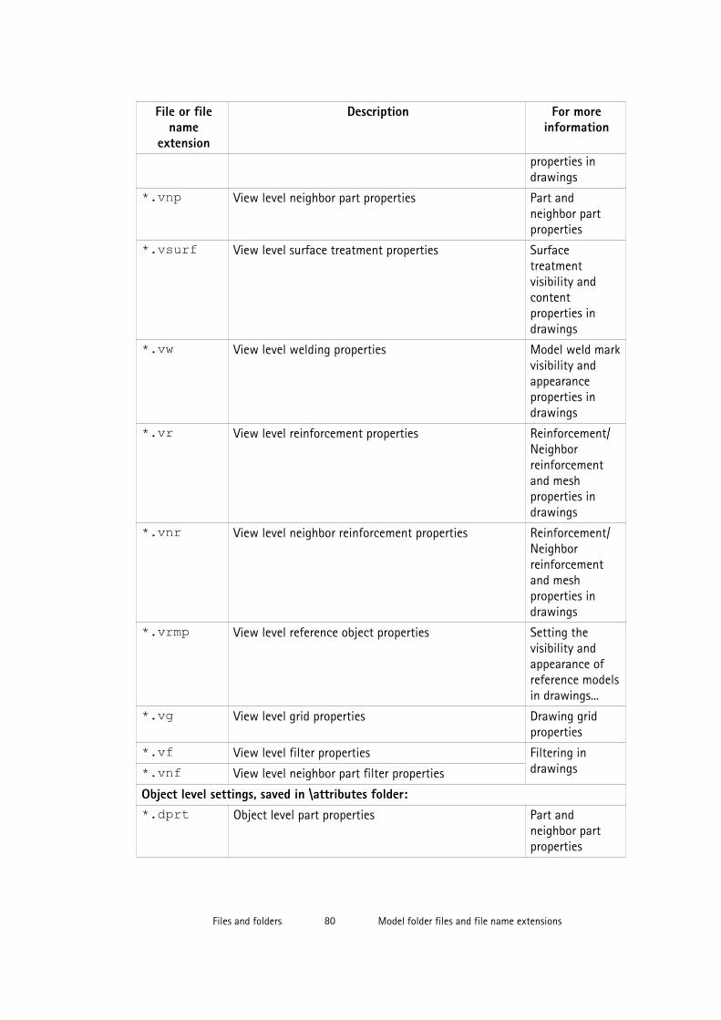
File or filename
extension
Description For moreinformation
properties indrawings
*.vnp View level neighbor part properties Part andneighbor partproperties
*.vsurf View level surface treatment properties Surfacetreatmentvisibility andcontentproperties indrawings
*.vw View level welding properties Model weld markvisibility andappearanceproperties indrawings
*.vr View level reinforcement properties Reinforcement/Neighborreinforcementand meshproperties indrawings
*.vnr View level neighbor reinforcement properties Reinforcement/Neighborreinforcementand meshproperties indrawings
*.vrmp View level reference object properties Setting thevisibility andappearance ofreference modelsin drawings...
*.vg View level grid properties Drawing gridproperties
*.vf View level filter properties Filtering indrawings*.vnf View level neighbor part filter properties
Object level settings, saved in \attributes folder:*.dprt Object level part properties Part and
neighbor partproperties
Files and folders 80 Model folder files and file name extensions

File or filename
extension
Description For moreinformation
*.dim Object level dimension properties Dimension anddimensioningproperties
*.pm Object level part mark properties Mark properties
*.jm Object level connection mark properties
*.sm Object level bolt mark properties
*.rm Object level reinforcement mark properties
*.mrms Object level merged reinforcement mark properties
*.surfm Object level surface treatment mark properties
*.note Object level associative note properties
*.wls Object level weld mark properties Weld markproperties
*.lev Object level level mark properties Level markproperties
*.rev Object level revision mark properties Adding revisionmarks
*.drmsh Object level reinforcement mesh properties Reinforcement/Neighborreinforcementand meshproperties indrawings
*.drbr Object level reinforcement properties Reinforcement/Neighborreinforcementand meshproperties indrawings
*.sc Object level bolt properties Bolt content andappearanceproperties indrawings
*.srf Object level surface treatment properties Surfacetreatmentvisibility andcontentproperties indrawings
*.dgr Object level grid properties Drawing gridproperties
Files and folders 81 Model folder files and file name extensions
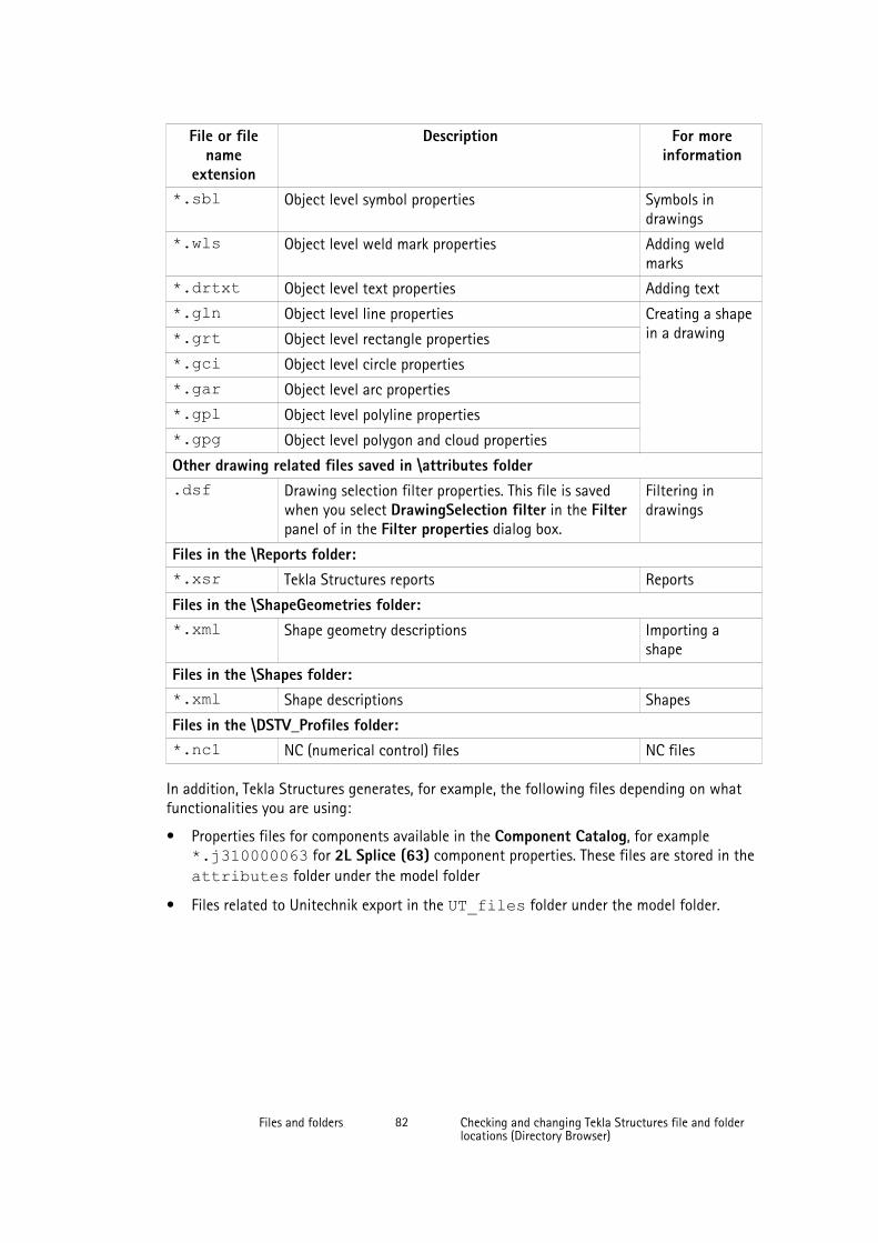
File or filename
extension
Description For moreinformation
*.sbl Object level symbol properties Symbols indrawings
*.wls Object level weld mark properties Adding weldmarks
*.drtxt Object level text properties Adding text
*.gln Object level line properties Creating a shapein a drawing*.grt Object level rectangle properties
*.gci Object level circle properties
*.gar Object level arc properties
*.gpl Object level polyline properties
*.gpg Object level polygon and cloud properties
Other drawing related files saved in \attributes folder.dsf Drawing selection filter properties. This file is saved
when you select DrawingSelection filter in the Filterpanel of in the Filter properties dialog box.
Filtering indrawings
Files in the \Reports folder:*.xsr Tekla Structures reports Reports
Files in the \ShapeGeometries folder:*.xml Shape geometry descriptions Importing a
shape
Files in the \Shapes folder:*.xml Shape descriptions Shapes
Files in the \DSTV_Profiles folder:*.nc1 NC (numerical control) files NC files
In addition, Tekla Structures generates, for example, the following files depending on whatfunctionalities you are using:
• Properties files for components available in the Component Catalog, for example*.j310000063 for 2L Splice (63) component properties. These files are stored in theattributes folder under the model folder
• Files related to Unitechnik export in the UT_files folder under the model folder.
Files and folders 82 Checking and changing Tekla Structures file and folderlocations (Directory Browser)

3.15 Checking and changing Tekla Structures file and folder locations(Directory Browser)
Directory Browser is a tool that helps you to find and modify the location of the variousTekla Structures files and folders, and customize user settings.
Generally, only administrators should change these settings. If you change themyourself, and you are using the same model with other users, and your settingsdiffer from those of the project, you will have problems. Also, adding or modifyingfiles in some of these folders may require administrator rights.
To locate files and folders, and customize your Tekla Structures settings:
1. Select Tools --> Macros... to open the Macros dialog box.
2. Select DirectoryBrowser and click Run.
The Directory Browser dialog box is displayed. Here you can check the most commonfolder paths, and customize the settings in your user.ini file, or in the user-specificor model-specific options.ini file.
3. Check the folder paths and change them if necessary by clicking the buttons on the leftof the Basic tab.
If you click the Project or Firm button and you have not set your firm and project folder,Tekla Structures will prompt you to do so and add the folder path definition to youruser.ini file.
4. Check the settings in the user.ini and options.ini files and change them ifnecessary by clicking the buttons on the right of the Basic tab.
5. Go to the Advanced tab and define the folder paths for additional folders that you mayneed to access, such as custom components and macros.
To display the location of your own user settings, click User Settings on the left. If you wantto check or change the content in one of your user settings files, click the User Settings(user.ini) or the User Specific Settings (options.ini) button to open the file.
Example
Files and folders 83 Checking and changing Tekla Structures file and folderlocations (Directory Browser)

3.16 Folder search order
When you open a model, Tekla Structures searches for the associated files in specific foldersin a set order.
It is important that you keep files in correct folders. Once Tekla Structures finds theassociated files, it stops searching. This means that files that have the same name but arelocated lower down the search order are ignored.
The folder search order is:
Folder Defined byCurrent model The open model
Project Advanced option XS_PROJECTFirm Advanced option XS_FIRM
Files and folders 84 Folder search order
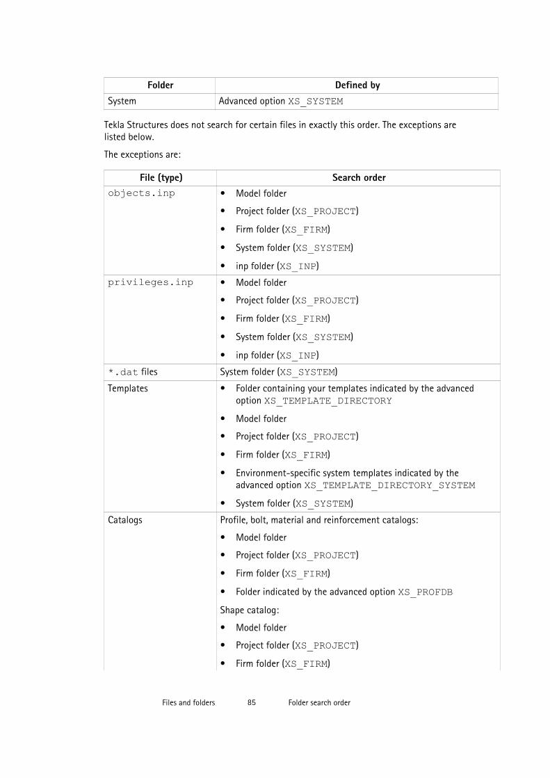
Folder Defined bySystem Advanced option XS_SYSTEM
Tekla Structures does not search for certain files in exactly this order. The exceptions arelisted below.
The exceptions are:
File (type) Search orderobjects.inp • Model folder
• Project folder (XS_PROJECT)
• Firm folder (XS_FIRM)
• System folder (XS_SYSTEM)
• inp folder (XS_INP)
privileges.inp • Model folder
• Project folder (XS_PROJECT)
• Firm folder (XS_FIRM)
• System folder (XS_SYSTEM)
• inp folder (XS_INP)
*.dat files System folder (XS_SYSTEM)
Templates • Folder containing your templates indicated by the advancedoption XS_TEMPLATE_DIRECTORY
• Model folder
• Project folder (XS_PROJECT)
• Firm folder (XS_FIRM)
• Environment-specific system templates indicated by theadvanced option XS_TEMPLATE_DIRECTORY_SYSTEM
• System folder (XS_SYSTEM)
Catalogs Profile, bolt, material and reinforcement catalogs:
• Model folder
• Project folder (XS_PROJECT)
• Firm folder (XS_FIRM)
• Folder indicated by the advanced option XS_PROFDBShape catalog:
• Model folder
• Project folder (XS_PROJECT)
• Firm folder (XS_FIRM)
Files and folders 85 Folder search order

File (type) Search order• System folder (XS_SYSTEM)
• Folder indicated by the advanced option XS_DEFAULT_BREP_PATH
Printer catalog:
• Model folder
• Project folder (XS_PROJECT)
• Firm folder (XS_FIRM)
• Folder indicated by the advanced option XS_DRIVER
Do not use the system folder to store customized files. That way you will avoidhaving problems or doing a lot of unnecessary work when you upgrade to a newerversion of the software.
3.17 Project and firm folders
You can create project and firm folders for customized files. This is a useful technique if youwant to store the files for future use, or want to retain them when you install a new release.The project folder is where you should store files you customize for a particular project. Usethe firm folder to store files customized for a particular organization or company. Create firmand project folders manually and make them available in all versions using the advancedoptions XS_PROJECT and XS_FIRM in Tools --> Options --> Advanced Options... -->File Locations .
For example, you regularly work for a company that has specific drawing layout standards itexpects you to use. Customize the drawing templates once for the company and save them ina sub-folder located under the firm folder. You can then use the customized drawingtemplates for all future projects for that company.
Changing an advanced option value in .ini files located outside the modelfolder does not affect the existing models. You can only update advanced optionsin the Advanced Options dialog box or in the options.ini file located inmodel folder; not from an options.ini file located in folders defined for theadvanced options XS_FIRM or XS_PROJECT. The .ini files are read alsowhen you open an existing model, but only new advanced options that do notexist in options_model.db or options_drawings.db are inserted, for
Files and folders 86 Project and firm folders
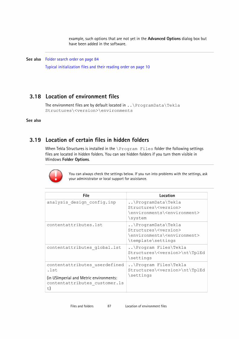
example, such options that are not yet in the Advanced Options dialog box buthave been added in the software.
Folder search order on page 84
Typical initialization files and their reading order on page 10
3.18 Location of environment filesThe environment files are by default located in ..\ProgramData\TeklaStructures\<version>\environments
3.19 Location of certain files in hidden foldersWhen Tekla Structures is installed in the \Program Files folder the following settingsfiles are located in hidden folders. You can see hidden folders if you turn them visible inWindows Folder Options.
You can always check the settings below. If you run into problems with the settings, askyour administrator or local support for assistance.
File Locationanalysis_design_config.inp ..\ProgramData\Tekla
Structures\<version>\environments\<environment>\system
contentattributes.lst ..\ProgramData\TeklaStructures\<version>\environments\<environment>\template\settings
contentattributes_global.lst ..\Program Files\TeklaStructures\<version>\nt\TplEd\settings
contentattributes_userdefined.lst(in USImperial and Metric environments:contentattributes_customer.lst)
..\Program Files\TeklaStructures\<version>\nt\TplEd\settings
See also
See also
Files and folders 87 Location of environment files
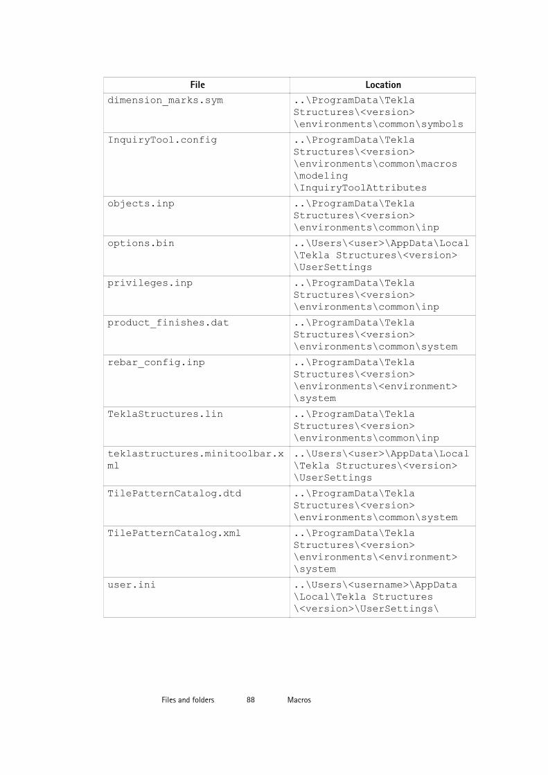
File Locationdimension_marks.sym ..\ProgramData\Tekla
Structures\<version>\environments\common\symbols
InquiryTool.config ..\ProgramData\TeklaStructures\<version>\environments\common\macros\modeling\InquiryToolAttributes
objects.inp ..\ProgramData\TeklaStructures\<version>\environments\common\inp
options.bin ..\Users\<user>\AppData\Local\Tekla Structures\<version>\UserSettings
privileges.inp ..\ProgramData\TeklaStructures\<version>\environments\common\inp
product_finishes.dat ..\ProgramData\TeklaStructures\<version>\environments\common\system
rebar_config.inp ..\ProgramData\TeklaStructures\<version>\environments\<environment>\system
TeklaStructures.lin ..\ProgramData\TeklaStructures\<version>\environments\common\inp
teklastructures.minitoolbar.xml
..\Users\<user>\AppData\Local\Tekla Structures\<version>\UserSettings
TilePatternCatalog.dtd ..\ProgramData\TeklaStructures\<version>\environments\common\system
TilePatternCatalog.xml ..\ProgramData\TeklaStructures\<version>\environments\<environment>\system
user.ini ..\Users\<username>\AppData\Local\Tekla Structures\<version>\UserSettings\
Files and folders 88 Macros
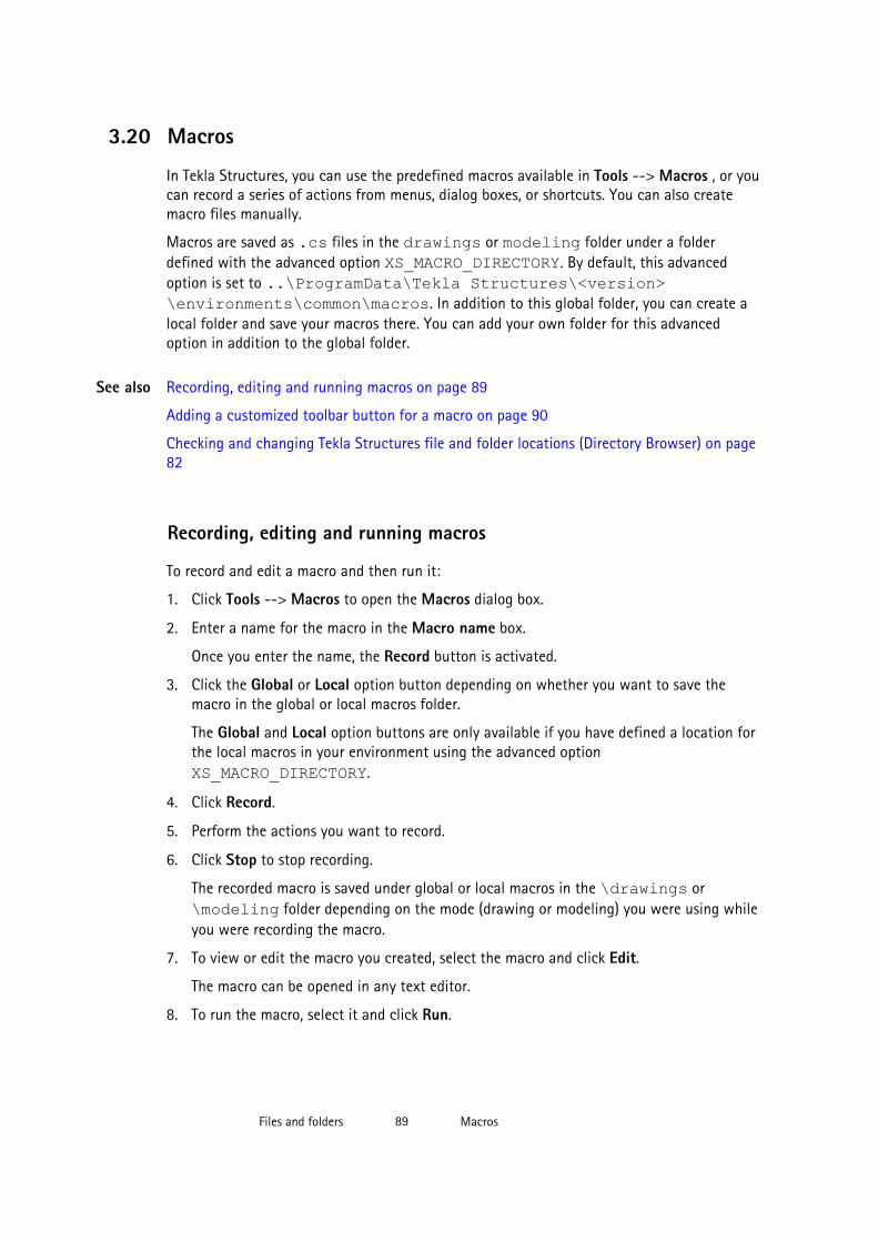
3.20 Macros
In Tekla Structures, you can use the predefined macros available in Tools --> Macros , or youcan record a series of actions from menus, dialog boxes, or shortcuts. You can also createmacro files manually.
Macros are saved as .cs files in the drawings or modeling folder under a folderdefined with the advanced option XS_MACRO_DIRECTORY. By default, this advancedoption is set to ..\ProgramData\Tekla Structures\<version>\environments\common\macros. In addition to this global folder, you can create alocal folder and save your macros there. You can add your own folder for this advancedoption in addition to the global folder.
Recording, editing and running macros on page 89
Adding a customized toolbar button for a macro on page 90
Checking and changing Tekla Structures file and folder locations (Directory Browser) on page82
Recording, editing and running macros
To record and edit a macro and then run it:
1. Click Tools --> Macros to open the Macros dialog box.
2. Enter a name for the macro in the Macro name box.
Once you enter the name, the Record button is activated.
3. Click the Global or Local option button depending on whether you want to save themacro in the global or local macros folder.
The Global and Local option buttons are only available if you have defined a location forthe local macros in your environment using the advanced option XS_MACRO_DIRECTORY.
4. Click Record.
5. Perform the actions you want to record.
6. Click Stop to stop recording.
The recorded macro is saved under global or local macros in the \drawings or\modeling folder depending on the mode (drawing or modeling) you were using whileyou were recording the macro.
7. To view or edit the macro you created, select the macro and click Edit.
The macro can be opened in any text editor.
8. To run the macro, select it and click Run.
See also
Files and folders 89 Macros
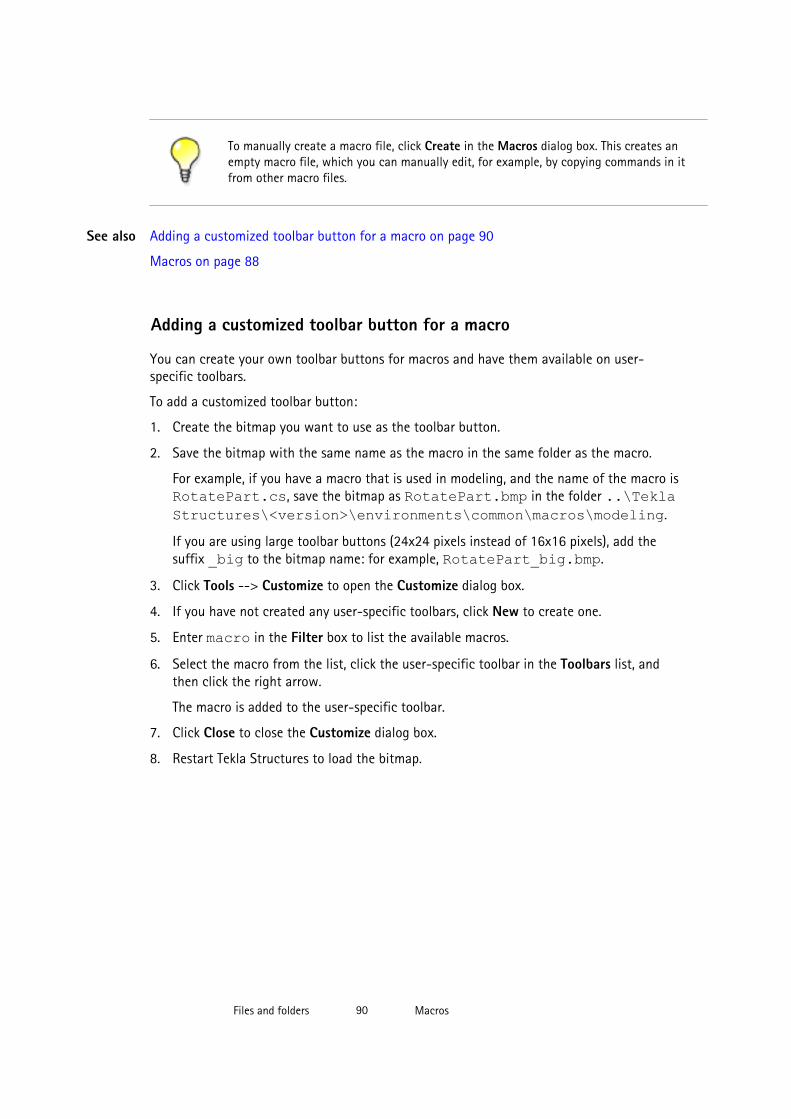
To manually create a macro file, click Create in the Macros dialog box. This creates anempty macro file, which you can manually edit, for example, by copying commands in itfrom other macro files.
Adding a customized toolbar button for a macro on page 90
Macros on page 88
Adding a customized toolbar button for a macro
You can create your own toolbar buttons for macros and have them available on user-specific toolbars.
To add a customized toolbar button:
1. Create the bitmap you want to use as the toolbar button.
2. Save the bitmap with the same name as the macro in the same folder as the macro.
For example, if you have a macro that is used in modeling, and the name of the macro isRotatePart.cs, save the bitmap as RotatePart.bmp in the folder ..\TeklaStructures\<version>\environments\common\macros\modeling.
If you are using large toolbar buttons (24x24 pixels instead of 16x16 pixels), add thesuffix _big to the bitmap name: for example, RotatePart_big.bmp.
3. Click Tools --> Customize to open the Customize dialog box.
4. If you have not created any user-specific toolbars, click New to create one.
5. Enter macro in the Filter box to list the available macros.
6. Select the macro from the list, click the user-specific toolbar in the Toolbars list, andthen click the right arrow.
The macro is added to the user-specific toolbar.
7. Click Close to close the Customize dialog box.
8. Restart Tekla Structures to load the bitmap.
See also
Files and folders 90 Macros

4 Model dump
If you have fatal problems with the model, for example, you cannot save the model, using amodel dump is one way of saving your work. Model dump creates an ASCII file. The filecontains your entire model including views and drawings.
The following information is for advanced users.
You can modify a model dump file with a standard text editor. For example, if youknow the ID of a corrupted part, you can search for the ID in the file and deletethe data related to the ID.
Importing a model dump on page 91
Exporting a model dump on page 91
4.1 Exporting a model dumpExporting a model dump creates an ASCII file of a model. You can import the model dumpinto a new model. The model dump file contains the entire model, including views anddrawings.
To export a model into a model dump file, click File --> Export --> Model Dump .
Tekla Structures creates the model.dmp file in the model folder.
Importing a model dump on page 91
See also
See also
Model dump 91 Exporting a model dump

4.2 Importing a model dump
You can only import a model dump into a newly-created model. A model dump can beimported only once into one model. You can import the same model dump into several newmodels.
To import a model dump:
1. Create a new model.
2. Copy the model dump file (.dmp) to the new model’s model folder.
3. Click File --> Import --> Model Dump .
4. Save and close the model.
5. Reopen the model.
Do not import model dumps in multi-user mode.
Exporting a model dump on page 91See also
Model dump 92 Importing a model dump
5 Disclaimer
© 2015 Tekla Corporation and its licensors. All rights reserved.
This Software Manual has been developed for use with the referenced Software. Use of theSoftware, and use of this Software Manual are governed by a License Agreement. Amongother provisions, the License Agreement sets certain warranties for the Software and thisManual, disclaims other warranties, limits recoverable damages, defines permitted uses of theSoftware, and determines whether you are an authorized user of the Software. Allinformation set forth in this manual is provided with the warranty set forth in the LicenseAgreement. Please refer to the License Agreement for important obligations and applicablelimitations and restrictions on your rights. Tekla does not guarantee that the text is free oftechnical inaccuracies or typographical errors. Tekla reserves the right to make changes andadditions to this manual due to changes in the software or otherwise.
In addition, this Software Manual is protected by copyright law and by international treaties.Unauthorized reproduction, display, modification, or distribution of this Manual, or anyportion of it, may result in severe civil and criminal penalties, and will be prosecuted to thefull extent permitted by law.
Tekla, Tekla Structures, Tekla BIMsight, BIMsight, Tedds, Solve, Fastrak and Orion are eitherregistered trademarks or trademarks of Tekla Corporation in the European Union, the UnitedStates, and/or other countries. More about Tekla trademarks: http://www.tekla.com/tekla-trademarks. Trimble is a registered trademark or trademark of Trimble Navigation Limited inthe European Union, in the United States and/or other countries. More about Trimbletrademarks: http://www.trimble.com/trademarks.aspx. Other product and company namesmentioned in this Manual are or may be trademarks of their respective owners. By referringto a third-party product or brand, Tekla does not intend to suggest an affiliation with orendorsement by such third party and disclaims any such affiliation or endorsement, exceptwhere otherwise expressly stated.
Portions of this software:
D-Cubed 2D DCM © 2010 Siemens Industry Software Limited. All rights reserved.
EPM toolkit © 1995-2004 EPM Technology a.s., Oslo, Norway. All rights reserved.
Open CASCADE Technology © 2001-2014 Open CASCADE SA. All rights reserved.
FLY SDK - CAD SDK © 2012 VisualIntegrity™. All rights reserved.
Teigha © 2003-2014 Open Design Alliance. All rights reserved.
PolyBoolean C++ Library © 2001-2012 Complex A5 Co. Ltd. All rights reserved.
Disclaimer 93 Importing a model dump

FlexNet Copyright © 2014 Flexera Software LLC. All Rights Reserved.
This product contains proprietary and confidential technology, information and creativeworks owned by Flexera Software LLC and its licensors, if any. Any use, copying, publication,distribution, display, modification, or transmission of such technology in whole or in part inany form or by any means without the prior express written permission of Flexera SoftwareLLC is strictly prohibited. Except where expressly provided by Flexera Software LLC in writing,possession of this technology shall not be construed to confer any license or rights under anyFlexera Software LLC intellectual property rights, whether by estoppel, implication, orotherwise.
To see the third party licenses, go to Tekla Structures, click Help --> About and click theThird party licenses button.
The elements of the software described in this Manual are protected by several patents andpossibly pending patent applications in the European Union and/or other countries. For moreinformation go to page http://www.tekla.com/tekla-patents.
Disclaimer 94 Importing a model dump

Index
Aadvanced options.............................................................. 10
changing...................................................................... 37storing settings.......................................................... 18user-specific................................................................33
API............................................................................................8
Ccatalog files........................................................................ 53clash check
settings......................................................................... 19company.ini.........................................................................10components
settings......................................................................... 19creating
customized initialization files................................16shortcuts...................................................................... 16
customized initializations...............................................16customizing
message files...............................................................50user-defined attributes............................................39
Ddata files..............................................................................49decimals
settings......................................................................... 19defining
flat bar sizes................................................................46unfolding parameters............................................... 47
dimensionsdefault format............................................................ 19default precision........................................................ 19default unit................................................................. 19settings......................................................................... 19
drawing objectssettings......................................................................... 19
Eenvironment settings
global default ............................................................ 13local...............................................................................14
environment variables..................................................... 18see advanced options............................................... 37
environment variables, see advanced options.......... 10environment.db..................................................................40environment
database file................................................................40env_<environment>.ini....................................... 10,14,32env_global_default.ini...............................................10,32env_global_default.ini ....................................................13examples
creating user-defined attribute.............................43flat bar sizes................................................................46modifying messages..................................................51updating user-defined attribute........................... 43
exportingmodel dump................................................................ 91
extensions..............................................................................8
Ffile name extensions........................................................ 62file types
initialization files.......................................................10files.......................................................................................... 9
extensions....................................................................62in model folder........................................................... 62initialization files.......................................................10locations.......................................................................82symbol...........................................................................55
firm folder........................................................................... 86flat bars
in drawings .................................................................46in reports......................................................................46sizes............................................................................... 46
fltprops.inp..........................................................................46folders..................................................................................... 9
95

firm................................................................................ 86in model folder........................................................... 62locations.......................................................................82project...........................................................................86search order................................................................ 84
font files...............................................................................54fonts......................................................................................54fonts_<lang>.ini................................................................10
Gglobal default environment settings........................... 13graphics card.........................................................................5
Iicons
adding customized toolbar buttons..................... 90image files...........................................................................56images
file formats..................................................................56importing
model dump................................................................ 91ini files............................................................................10,16
env_global_default.ini....................................... 13,14role_<role>.ini............................................................14
initialization files.............................................................. 10creating customized................................................. 16env_<environment>.ini........................................... 14env_global_default.ini............................................. 13file types.......................................................................10including other initialization files ....................... 18reading order.............................................................. 10role_<role>.ini............................................................14usage.............................................................................10
input files............................................................................ 38
Llang_<lang>.ini................................................................. 10load modeling
settings......................................................................... 19local environment settings
env_<environment>.ini........................................... 14location
of environmental files.............................................. 87
of hidden files.............................................................87locations
files................................................................................ 82folders........................................................................... 82
log fileslist of............................................................................. 57numbering.history log........................................ 59,61viewing......................................................................... 58viewing parts.............................................................. 58
Mmacros..................................................................................88
adding customized toolbar buttons..................... 90editing...........................................................................89global............................................................................ 89local...............................................................................89recording...................................................................... 89running......................................................................... 89
memory...................................................................................5message files...................................................................... 50
customizing.................................................................50messages
modifying.....................................................................51Migration Wizard.............................................................. 15model dump........................................................................91
exporting......................................................................91importing..................................................................... 91
model folderfile name extensions.................................................62files................................................................................ 62
model-specific settings................................................... 32mouse
settings......................................................................... 19
Nnorth marks, see orientation marks............................. 19numbering history.......................................................59,61numbering
settings......................................................................... 19user-defined attributes............................................43
Oobjects.inp........................................................................... 41
96
optimizingTekla Structures performance.................................. 5
Options dialog boxsettings......................................................................... 19
options.bin...................................................10,18,32,33,37options.ini......................................................................10,32options
storing saving............................................................. 18options_drawings.db...................................... 18,19,32,37options_model.db............................................18,19,32,37orientation marks
settings......................................................................... 19
Pperformance
modeling tips.................................................................6optimizing...................................................................... 5
platesflat bars........................................................................ 46
plotdev.bin...........................................................................55profile files.......................................................................... 53project folder......................................................................86properties files................................................................... 52properties
objects.inp................................................................... 41unfolding parameters............................................... 48
property files...................................................................... 51
Rreading order
initialization files.......................................................10recording
macros.......................................................................... 89report files...........................................................................55role settings........................................................................ 14roles.......................................................................................14role_<role>.ini....................................................... 10,14,32running
macros.......................................................................... 89
Ssaving
advanced options.......................................................18
options..........................................................................18search order........................................................................ 84settings
clash check.................................................................. 19components.................................................................19decimals....................................................................... 19dimensions...................................................................19drawing objects..........................................................19general..........................................................................19in the Options dialog box........................................19load modeling.............................................................19mouse............................................................................19north marks, see orientation marks..................... 19orientation marks...................................................... 19startup.......................................................................... 19units...............................................................................19
shortcutscreating........................................................................ 16customized initialization files................................18
standard files......................................................................51creating........................................................................ 52saving............................................................................52
standard.opt........................................................................19startup
settings......................................................................... 19symbol files......................................................................... 55system-specific settings..................................................32
TTekla Open API......................................................................8Tekla Structures files.......................................................... 9Tekla Structures folders..................................................... 9teklastructures.ini............................................................. 10template files..................................................................... 55tips
modeling large models............................................... 6toolbars
adding toolbar buttons for macros...................... 90
Uunfolding parameters
defining........................................................................ 47properties.....................................................................48
unfold_corner_ratios.inp................................................ 48units
97
settings......................................................................... 19updating
user-defined attributes in model..........................40user-defined attributes
customizing.................................................................39environment.db.......................................................... 40example........................................................................ 43numbering................................................................... 43objects.inp properties............................................... 41updating in model..................................................... 40
user-specific advanced options.................................... 33user-specific settings.......................................................32user.ini..................................................................................10
modifying.....................................................................15
Vvariables
see advanced options............................................... 33viewing parts
in log files.................................................................... 58viewing
log files.........................................................................58
98