Embed Size (px)
Citation preview

OPTIMUM SPACING AND DESIGN OF DRAINAGE CULVERTS IN THE HILLY STRETCH OF BUANGPUI –LUNGLEI STATE ROAD IN MIZORAM
S. K. Mazumder, Individual Consultant Aquagreen Engg. Mgt. (P) Ltd., ICT (P) Ltd. & SWI (P) Ltd., New Delhi
E-mail: [email protected] ABSTRACT
Large numbers of culverts are to be constructed in a hilly road for cross-drainage purpose for the safety and
efficient functioning of the road. Optimum spacing of culverts is governed by the type of terrain and its
steepness, road alignment, longitudinal slope of road, rainfall intensity and average width of catchment. An
economic analysis is performed to determine the optimum spacing of culverts in between ridge and valley
points of the road so that the total cost of culvert and drain is minimum. Hydrologic and hydraulic design
considerations for finding design discharge and carrying capacity of culverts are discussed. Typical
drawings for slab type and hume pipe culverts showing improved inlet and outlet transitions are presented.
Key Words: Culvert, Design, Hilly Terrain, Optimum Spacing, Transitions.
1 INTRODUCTION
Drainage of roads in both plain and hilly terrains is extremely important for improvement in riding quality,
safety as well as increasing life span of a road. Although the cost of longitudinal drainage (leaving cost of
bridges/culverts) varies from 1 to 2 percent of road cost, design of drainage is often neglected by the project
authorities resulting in lot of problems e.g. damage to road, poor riding quality, skidding, hydro planning
etc. Various objectives of road drainage are
• To remove storm water from road surface as rapidly as possible to avoid skidding, splashing, hydro
planning etc.
• To ensure road safety and prevent traffic hazards
• To prevent inundation of road surface from run-off / flood water in flowing streams since road acts
as a barrier to free run off movement that used to occur prior to road construction
• To ensure structural safety of road, bridges and culverts
• To maintain a healthy road, bridges and other cross-drainage works free from water congestion
settlement of embankment causing pot holes, undulations etc.
• To reduce/minimize maintenance cost and longer life span of the road
Essential requirements of an ideal road drainage system are summarized below:
• Run-off from the catchment area should be disposed as quickly as feasible.
• Run- off water from both sides of the terrain (road in valleys) or from upstream side (in terrains
with one side sloping) should be intercepted in a roadside drain so that run-off water moves to the
cross-drainage system quickly and a continuity of flow is maintained.
• Road must have adequate cross - slope or camber as per Clause 5 of IRC, SP-42(1994) for quick
disposal of storm water run-off laterally to the road side drain / drains.
• A minimum longitudinal grade of ½% should be provided to the road wherever possible for
facilitating both surface and sub - surface drainage.
• Adequate size and numbers of cross - drainage structures (Bridges and culverts) should be provided
to ensure safe and quick disposal of storm water
• Intercepting drain, as in a hilly terrain sloping towards the road, should have adequate size and be
connected properly with well designed culverts/bridges.
• In case width of terrain contributing flow to the drain is very high, intercepting drain at higher
elevation should be provided
• The drain should be connected to the cross drainage structures so designed that the water moves out
without any objectionable heading up/afflux and there is no overtopping of road and the hydraulic
structures.
• GSB /drainage layer should be provided for sub-surface drainage of percolating / seepage water as
well as for intercepting capillary water
This paper deals with the drainage requirement, planning and optimal spacing of culvers, hydrologic/
hydraulic design of culverts in the hilly stretch of Buangpui – Lunglei state road in the state of Mizoram
Proper planning of drainage culverts (Mazumder and Poudel,2002) in a hilly area like Mizoram and similar
terrains in the North-East of India is a prerequisite for a healthy road free from traffic hazards as well as for
durability of the road.
2 LOCATION OF CULVERTS IN THE HILLY STRETCH OF THE ROAD
Buangpui–Lunglei state road in Mizoram is a single lane state road mostly in the hilly terrain. It is propsed
to widen it to ½ specifications. Fig.1 shows the location of 170 existing drainage culverts (indicated by
arrows) in the hilly stretch of the road from 128.525 km to170.944km having a length of 42.414 km.. The
average distance between consecutive culverts is about 250 m or in other words about 4 numbers of culverts
are provided per km of road. In such a terrain with high rainfall intensity, perhaps more culverts should have
been provided. In this stretch of road, there is only one bridge over river Tlwang and as such the culverts
form the lifeline of the drainage system. Location and spacing of culverts are generally governed by three
major factors, namely,
(a) Width of the catchment (i.e. the distance between the road and the terrain ridgeline normal to the
road) contributing runoff towards the road
(b) Rainfall intensity in the catchment
(c) Longitudinal slope of the road
Culverts are to be provided at all valley points where the road crosses torrents for passing the storm water to
the valley. In addition, the intermediate culverts are necessary in order to limit the size of the drains running
parallel to the road at the foothill for intercepting run-off and disposing it to the valley side through the
drainage culverts. Too wide a drain along foothill will increase the cost of hill excavation besides
destabilizing hill slope. Costly slope protection measures are to be adopted for stabilizing the hill slope.
Usually Vee-shaped triangular open drains of depth varying from 30cm to 40cm with road-side slope (of
the drain) not exceeding 3(H): 1(V) is recommended by hill-road manual ( IRC-48,1998) to avoid traffic
hazard. As such, the carrying capacity of the drain, depending on size and longitudinal slope of the drain
(which is almost same as that of the road) is limited. If the spacing of intermediate culverts is too far, the
drains will overflow, especially near outfall points and damage the road. In the built-up areas, however,
covered trapezoidal concrete/boulder drains (IRC:SP-50,1999) have been provided in order to increase
conveying capacity of the drain with a view to protect the built-up / habitated areas from run-off hazards.
3 BLOCKAGE OF DRAINS / CULVERTS AND DAMAGE TO ROAD SURFACE
Author visited the existing road and the adjoining drainage system from Buangpui to Lunglei. Most of the
drains have been overflowing causing immense damage to the road surface as evident from photographs 1
and 2. It is noticed that the drains and culvert inlets are blocked due to deposition of stones and debris
falling from hills, especially in areas susceptible to slip failure of hill face in the unstable regions, resulting
in loss of drain and culvert capacity. Due to undersized culverts and their blockage by debris and jungles
(phtograph-3), choking of the drains, poor cross slope and excessive long slope of road, growth of jungles in
the valley side curbs (there is hardly any maintenance), run-off water from the hills virtually move all along
the road surface causing erosion of bituminous top surface and extensive damage to the road as evident
from the photographs..
4. TYPE, SIZE, SPACING AND CARRYING CAPACITY OF CULVERTS
Majority of the existing culverts are made of Hume pipes (HP) of sizes varying from 60 cm to 100 cm. Box
type concrete culverts are provided to augment culvert capacities wherever required (photograph-4).To
ensure smooth and free flow, slab-type culverts with masonry abutments having spans varying from 2m to
5m are provided in all such locations where the discharge is very high and the torrents carry debris, gravels
and boulders during flood season.As already mentioned earlier, average distance between consecutive
culverts is about 250 m. With a view to examine whether the spacing is adequate or not, an economic study
is made to determine the optimum spacing of the intermediate culverts, as discussed in the following
paragraphs. Drainage capacity of culverts should be equal to or more than the incoming flow from the
adjoining drains and the torrents discharging in to the culverts i.e. the total runoff generated from the
catchment contributing

Fig.1 Culverts in the Hilly Stretch of Buangpui-Lunglei State Road in Mizoram (Arrowheads Indicate Location of Culverts)

PHOTOGRAPH-1 PHOTOGRAPH-2
(Showing Highly Damaged Road Surface)
flow to the culverts. Design methodology of drains are given in IRC-SP:42 (1994), (IRC:SP-50,1999), Hill
Road Manual (IRC-48,1998), Drainage Design Manual (2002), AASHTO (1992), HEC-12 (1984).
Hydraulic Design procedure of culverts are given in IRC-SP-!3 (2004), AASHTO (1975), USBR(1968).
Because of steep slope of culverts discharging in the valley (resulting in shooting supercritical free flow at
outlet), most of the culverts are of inlet control types. Since top of culverts are to be below road crust, the
culvert inverts at entry are to be lowered by providing catch pits of adequate depth to accommodate them.
Water from the drains drops into the catch pit, heads up and then starts flowing through the culverts to
dispose the design discharge when the head is maximum.
Discharging capacity (Qc) of HP culverts under inlet control can be expressed as
Qc=C A (2gHw)1/2
where C is the coefficient of discharge depending on whether the head (Hw ) is measured above invert or
from the center of conduit, head to depth ratio (Hw/D), D being the height of opening of the conduit at the
inlet and the inlet geometry. A is the cross sectional area of flow of the conduit at entry in the plane of inlet
headwall (for a HP culvert A= (π/4) D2, g is acceleration due to gravity.
Depth of catch pits is found to vary from 2m to 4m, depending on terrain conditions, size of drain at its
outfall and depth of culvert etc. It is noticed that many of the culverts are blocked at inlet since the catch pits
are full of large size stones and debris carried by the drains as well as the torrents.

Photograpph-3
(Showing Growth of Jungles Upstream of a Slab Culvert)
Photograph-4 (Showing a Box Type Culvert by the Side of a HP Culvert to Augment Flow Capacity) At many places, the blockage of inlet (photograph-3) has resulted in loss of carrying capacity of culverts, heading up of water level and overtopping of road resulting in damage to the road, inconvenience to traffic and slowing down of the vehicle speed . Inlet transition connecting the torrent with culvert has been modified to improve the carrying capacity and free movement of stones. 5. OPTIMUM SPACING OF CULVERTS As stated earlier, if the distance between consecutive culverts is too large, size of drain will increase and
hence its cost; but the total number of culverts will reduce and hence the total cost of culverts will be less.
On the contrary, if the spacing is too small, the total number of culverts and culvert cost will be more but the
size and cost of drain will reduce. An economic analysis is, therefore, made to examine at what spacing of
culverts, the total cost of drain and culverts becomes minimum.

Total cost of drain and culvert is computed per kilometre of road. A fixed size of 1m diameter HP culvert is
considered for the economic analysis. If S is the assumed spacing of culverts in meter, number of culverts of
1m diameter shall be 1000/S per km of road.
As stated earlier, the three most important parameters which govern the size and cost of drain are
(i) width and steepness of the catchment (i.e. the distance between the road and the ridgeline) contributing
runoff towards the road, (ii) rainfall intensity in the catchment and (iii)longitudinal slope of the road/drain.
For any assumed spacing of culverts, the size of drain is found by computing run-off from the catchment
contributing flow into the culvert. The maximum flow computed from the design rainfall intensity (on the
basis of deign storm of 25 year return period) and the catchment area is determined by using Rational
formula:
Q = 0.028 f PIcA
where Q is the design discharge in cumec, f is spread factor, P is run-off coefficient depending on
permeability and slope of catchment, Ic is design rainfall intensity (corresponding to time of concentration)
in cm/hr and A is the catchment area in hectare. Size of drain to carry the design discharge (Q) is determined
by using Manning’s formula:
Qc = 1/n (AR2/3 S01/2)
where Qc is the carrying capacity of drain in cumec, n is rugosity coefficient, A is the cross – sectional area
of flow in the drain in m2, R is hydraulic mean depth in m and S0 is the longitudinal slope of the drain. Drain
size was fixed so that Q = Qc. Knowing the drain size, cost of stone pitched drain - both Vee-type and
trapezoidal covered drains (depending on spacing of culverts and size of drain) is computed. Cost of 1000/S
number of H.P. culverts of 1m diameter along with cost of catch pit, inlet and outlet transitions etc. is
computed Total cost of drain and culvert per kilometre of road is found by adding up the cost of drain with
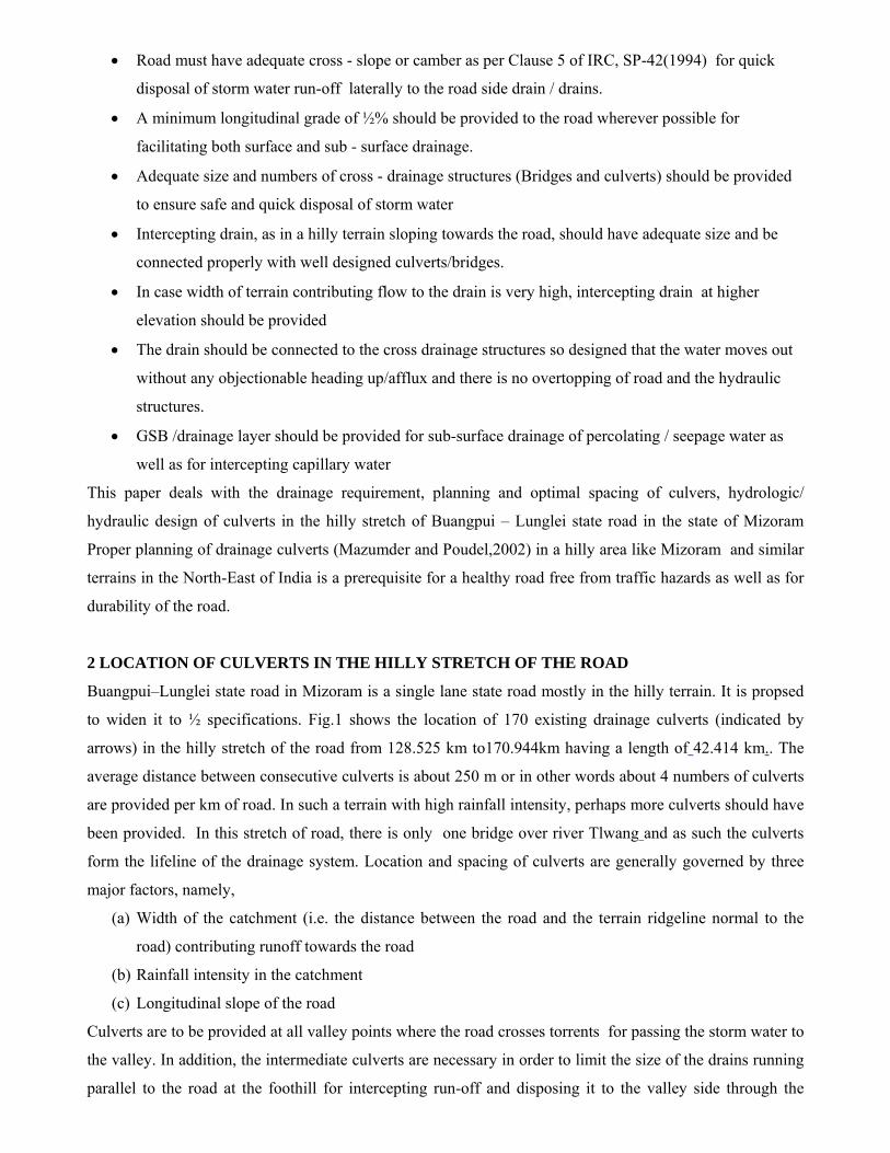
cost of culverts. The total cost so found is plotted against spacing of culverts assumed. Fig.2 is one of the
typical plots showing the cost of drain, cost of culvert and total cost of drain and culvert against different
assumed spacing of culverts for a 50 m width of catchment and a road slope of 3%. Optimum spacing of
culverts corresponding to minimum total cost is found to be 170m. Similar curves are plotted for 70m and
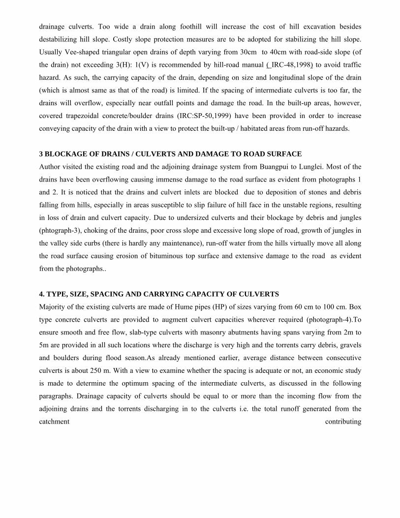
125m width of catchment for 7 different road slopes varying from 1% to 7%. Fig.3 shows a typical plot of
total cost of drain and culvert against different spacing of culverts for 7 different slopes of road varying from
1% to 7%. Similar plots are made for 70m and 125m widths of catchment. The locus of optimum spacing of
culverts corresponding to minimum total cost is indicated by dashed line in Fig.3. A master table is prepared
from Fig.3 and similar figures for other widths of catchment giving the optimum spacing of culverts, as
illustrated in table-1.
Table-1 shows that optimum spacing of culverts increase with increases in road slope for a given width of
catchment and decreases with increase in width of catchment for any given slope of road. It may be

mentioned that table-1 and the figures-2 and 3 are applicable only for the design rainfall of 25 year return
period found from iso-pluvials for the Buangpui-Lunglei region,subzone:2 (c) covering Mizoram state
(CWC-2c )
6 IMPROVED INLET AND OUTLET TRANSITIONS FOR CULVERTS
During the site investigations and field data collection for the existing drains and culverts, it has been
observed that the inlet and outlet transitions of the Box/HP culverts are not properly designed. Inlet catch
pits where the drains drop abruptly are mostly filled with stones and debris resulting in substantial loss of
head causing rise in head water elevation , overflow and damage to the road. Similarly, the outlets are found
to end abruptly without any transition for diffusion of high velocity jet flow with high discharge intensity
coming out of the culverts. There is hardly any downstream protection resulting in scouring of ground, lack
of safety to the culvert and endangering the hill slope stability downstream of the culvert. Although debris
can be removed manually, it is difficult to lift the heavy stones from deep catch pits. It is also noticed that
during the non-monsoon season when most of the torrents run dry, the local people collect subsurface
ground water by driving bamboo pieces inside the hill adjoining the torrents upstream of the culvert with
great difficulty.
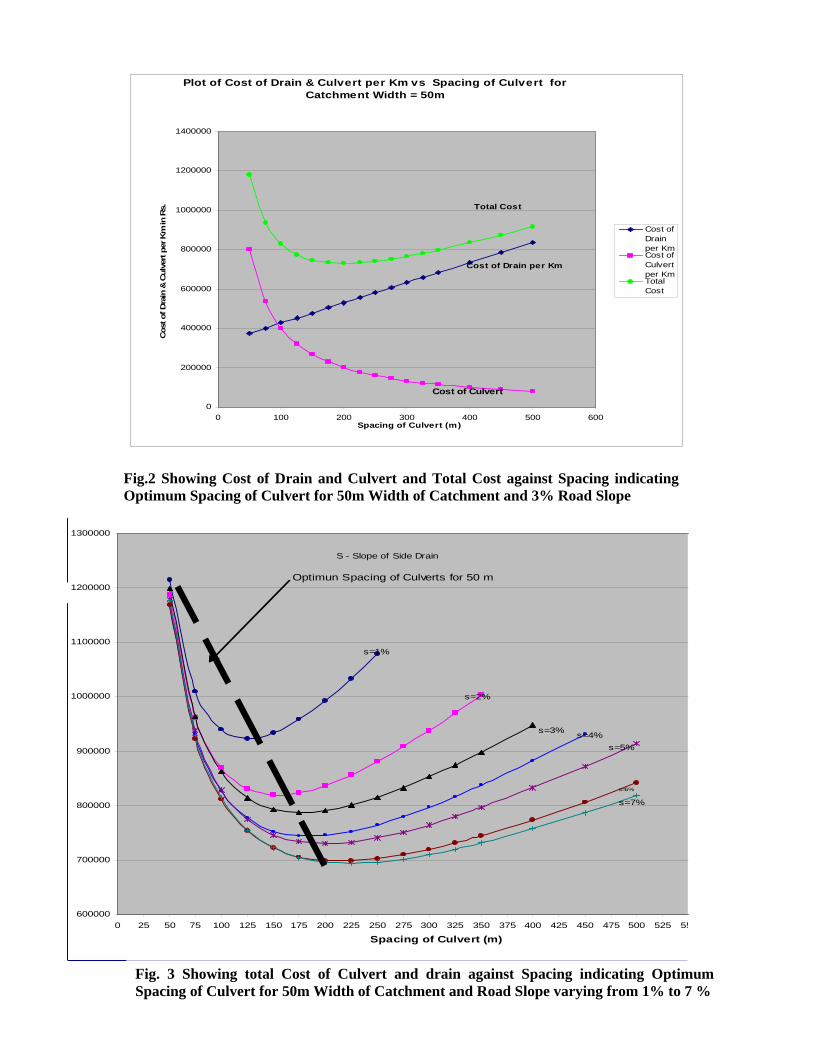
Keeping all the above points in view, the inlet and outlet transitions are modified as shown in Fig. 4 (slab
culverts) and Fig.5 (H.P/Box culverts). Since the road is to be widened from one lane to one and half lane by
excavating rocks in the hill side upstream of culvert, the existing catch pits at inlets have to be filled in and
new inlets are to be built. Instead of providing one deep catch pit, it is divided in to two shallow pits in the
improved design of inlet. The upper pit is provided with a concrete overflow type weir to intercept heavy
stones moving with flow while the lower pit will receive comparatively clear water with sand and smaller
stones which will easily move out of the culverts. The upper pit with the front weir and side walls is so
designed that it forms a wide pool of water and act as temporary storage for the heavier stones and water
which can be easily collected by the local people for domestic use.
At the outlet, floor is stepped and bed is paved with stone pitching in between the flaring side walls for
energy dissipation and flow diffusion. The downstream protection works is to be extended up to a distance
so that the flow velocity and discharge intensity at the exit of protection works is sufficiently reduced
without causing any objectionable scour downstream. It is, however, necessary to periodically remove the
stones and debris from the upper pit for its efficient functioning. Similarly, the downstream protection works
may need repair after the monsoon flood.
SUMMARY AND CONCLUSION
Buangpui-Lunglei state road in Mizoram is proposed to be widened from existing single lane to ½
specifications lane. The road is badly damaged due to inadequate number of drainage culverts most of which
are found to be choked due to stones and debris deposited in the deep catch pit at entry to the culverts.

Capacity of the culverts is substantially reduced due to growth of jungles at the inlets. An economic study
for determining optimum spacing of drainage culverts has been carried out. It is found that the optimum
spacing decreases with increase in width of catchment for any given slope and increases with increase in
road slope for any given width of catchment. Typical cases of optimum spacing corresponding to minimum
total cost of culverts and drains per kilometer of road are illustrated figures 2 and 3 and are summarized in
table-1- applicable for the design rainfall intensity in the Buangpui-Lunglei area in Mizoram state. In order
to overcome the various difficulties, an improved design of inlet and outlet transitions as illustrated in
Figures 4 and 5 are recommended for efficient functioning of the drainage culverts for this road.
600000
700000
800000
900000
1000000
1100000
1200000
1300000
0 25 50 75 100 125 150 175 200 225 250 275 300 325 350 375 400 425 450 475 500 525 55
Spacing of Culvert (m)
s=1%
s=2%
s=3% s=4% s=5%
s=6%
s=7%
S - Slope of Side Drain
Optimun Spacing of Culverts for 50 m
Fig. 3 Showing total Cost of Culvert and drain against Spacing indicating Optimum Spacing of Culvert for 50m Width of Catchment and Road Slope varying from 1% to 7 %
Fig.2 Showing Cost of Drain and Culvert and Total Cost against Spacing indicating Optimum Spacing of Culvert for 50m Width of Catchment and 3% Road Slope
Plot of Cost of Drain & Culvert per Km vs Spacing of Culvert for Catchment Width = 50m
0
200000
400000
600000
800000
1000000
1200000
1400000
0 100 200 300 400 500 600Spacing of Culvert (m)
Cos
t of D
rain
& C
ulve
rt p
er K
m in
Rs.
Cost ofDrainper KmCost ofCulvertper KmTotalCost
Total Cost
Cost of Drain per Km
Cost of Culvert

Fig.4 Showing Improved Inlet and Outlet Transitions for Slab Culverts
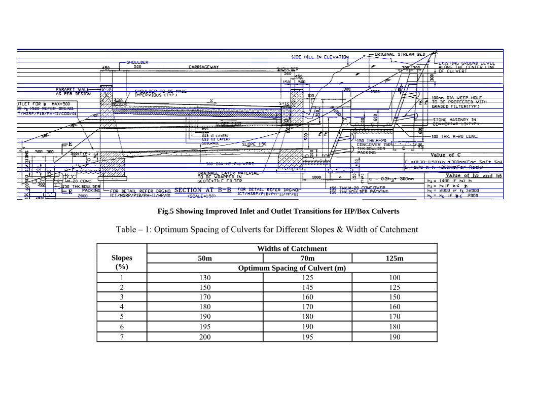
Fig.5 Showing Improved Inlet and Outlet Transitions for HP/Box Culverts
Table – 1: Optimum Spacing of Culverts for Different Slopes & Width of Catchment
Widths of Catchment 50m 70m 125m
Slopes
(%) Optimum Spacing of Culvert (m) 1 130 125 100 2 150 145 125 3 170 160 150 4 180 170 160 5 190 180 170 6 195 190 180 7 200 195 190
ACKNOWEDGEMENT
Author wishes to convey his gratitude to M/S ICT Pvt. Ltd, New Delhi, for all the co-operation and help
received for writing the paper.
REFERENCES
AASHTO (1975) ‘Guidelines for the Hydraulic Design of Culverts’ prepared .by Task Force on Hydrology
and Hydraulics Sub-Committee on Design, American Association of State Highways and Transport
Officials, Washington D.C. 20045, USA
AASHTO (1992) ‘Highway Drainage Guidelines, Storm Water Drainage Systems’, Vol..9, American
Association of State Highways and Transport Officials, Washington D.C. 20045, USA
CWC-2 (c) ‘Flood Estimation Report for Barak and Others’ Sub-zone (2c )’ ,– A Joint Work of Central
Water Commission (CWC), Indian Meteorological Deptt (IMD), Research, Design and Standards
Organisation (RDSO) and Ministry of Shipping, Highways & Road Transport (MOSHRT), pub. by
Directorate of Hydrology, CWC, New Delhi.
Ethiopian Roads Authoriy (2002) ‘Drainage Design Manual’, Govt. of Ethiopia.
FHWA ‘Hydraulic Design of Highway Culverts’ Hydraulic Design Series No.5 (HDS5), Federal Highways
Administration, USA
HEC-12 (1984), ‘Drainage for Highway Pavements’pub. by U.S.Federal Highway Administration,
IRC:SP-42 (1994), “Guidelines on Road Drainage”, Published by Indian Roads Congress, R.K.Puram, New Delhi
IRC:SP-48 (1998) ‘Hill Road Manual’ pub. by Indian Roads Congress, R.K.Puram, New Delhi.
IRC:SP-50 (1999) ‘Guidelines for Urban Drainage’ pub. by Indian Roads Congress, R.K.Puram, New Delhi
IRC:SP-13 ((2004) “Guidelines for the Design of Small Bridges and Culverts”, Published by Indian Roads
Congress, New Delhi.
IRC-5 (2004) “Standard Specifications and Code of Practice for Road Bridges – Section 1” Published by
Indian Roads Congress, R.K.Puram, New Delhi

Mazumder, S.K., and Poudel, P.R.(2002) “Planning and Design of Culverts in a Hilly terrain in Mizoram”
Proc. of HYDRO-2002 on “Hydraulics, Water Resources & Ocean Engineering” org by ISH & IIT, Mumbai
USBR (1968) ‘Design of Small Dams’, (Int. Edition) Chapter-F ‘Hydraulics of Spillways-Culvert
Hydraulics’pp326-333, pub. by Oxford & IBH pub. Co Ltd. New Delhi and Kolkata.