Embed Size (px)
Citation preview

User Manual Version 1.0.0

Microgate MicroTab LED User Manual Page 2 of 84
Contents
1 Hardware ............................................................................................................................................................. 5
1.1 Control Panel ...................................................................................................................... 6
1.2 Right Side Panel .................................................................................................................. 7
1.3 Connections ......................................................................................................................... 8
1.4 Power supply ...................................................................................................................... 9
1.4.1.1 Battery Charging ................................................................................................... 9
1.5 Modular System ................................................................................................................ 11
1.5.1 Configuration Examples ............................................................................................... 11
1.5.2 Assembly ....................................................................................................................... 13
1.6 Radio System..................................................................................................................... 16
1.7 Firmware Updating .......................................................................................................... 17
1.8 Hardware Reset ................................................................................................................ 18
1.9 Brightness Sensor ............................................................................................................. 19
2 Internal Programs .......................................................................................................................................... 20
2.1 General Setup .................................................................................................................... 21
2.2 Base Program .................................................................................................................... 23
2.2.1 Setup .............................................................................................................................. 24
2.3 Internal Program (user programs) ................................................................................. 25
2.3.1 Setup .............................................................................................................................. 25
2.4 Timer (Chronometer) ...................................................................................................... 26
2.4.1 Setup .............................................................................................................................. 26
2.5 Speedmeter ....................................................................................................................... 28
2.5.1 Setup .............................................................................................................................. 30
2.6 Countdown ........................................................................................................................ 32
2.6.1 Start Time 1 ................................................................................................................... 32
2.6.1.1 Setup ..................................................................................................................... 32
2.6.2 Start Time 2 ................................................................................................................... 33
2.6.3 Time to Zero .................................................................................................................. 34

Microgate MicroTab LED User Manual Page 3 of 84
2.6.3.1 Setup ..................................................................................................................... 34
2.7 Clock .................................................................................................................................. 35
2.7.1 Setup .............................................................................................................................. 35
2.8 Date & Clock ...................................................................................................................... 36
2.8.1 Setup .............................................................................................................................. 36
2.9 Lap Timer .......................................................................................................................... 37
2.9.1 Setup .............................................................................................................................. 37
2.10 Test Pixel ........................................................................................................................... 39
2.11 Self Timer and Parallel Self Timer .................................................................................. 40
2.12 OSM6 .................................................................................................................................. 41
2.12.1 Setup .......................................................................................................................... 41
2.13 Powertime ......................................................................................................................... 42
2.14 Alge .................................................................................................................................... 43
2.14.1 Setup .......................................................................................................................... 43
2.14.2 Note For the Connection of Chronometers ............................................................ 43
2.15 Omega ................................................................................................................................ 44
2.15.1 Setup .......................................................................................................................... 44
2.15.2 Note For the Connection of Chronometers ............................................................ 45
2.16 Stalker ................................................................................................................................ 46
2.16.1 Setup .......................................................................................................................... 46
2.17 Jugs..................................................................................................................................... 47
2.17.1 Setup .......................................................................................................................... 47
2.18 Athletic .............................................................................................................................. 48
2.18.1.1 Setup ..................................................................................................................... 48
2.18.2 Counter ...................................................................................................................... 48
2.18.3 Countdown ................................................................................................................ 48
2.18.3.1 Setup ..................................................................................................................... 48
2.18.4 Wind .......................................................................................................................... 49
2.18.4.1 Setup ..................................................................................................................... 49
3 Transmission protocol .................................................................................................................................. 50

Microgate MicroTab LED User Manual Page 4 of 84
3.1 Text Frame (ALPHA Protocol) ......................................................................................... 52
3.1.1 Text Frame Syntax and Command Table .................................................................... 54
3.1.2 AutoConfig Commands................................................................................................. 61
3.2 Graphical Frame (GRAPH Protocol) ................................................................................ 63
3.2.1 Active Objects ............................................................................................................... 64
3.2.2 Proportional and Non-Proportional Fonts ................................................................. 64
3.2.3 Graphical Frame Syntax and Command Table ........................................................... 66
3.2.3.1 Example ................................................................................................................ 71
3.3 Unicode Frame ................................................................................................................... 72
3.3.1 Graphical Unicode Frame Syntax and Command Table ................................................ 72
3.3.1.1 Example ................................................................................................................ 73
4 Microgate.DispBoard.Manager API ......................................................................................................... 74
4.1 Constructor ....................................................................................................................... 75
4.2 Connection ........................................................................................................................ 75
4.3 Overload of Some Methods .............................................................................................. 76
4.4 Main Methods ................................................................................................................... 77
4.5 Example ............................................................................................................................. 78
4.6 Methods ............................................................................................................................. 79
4.7 Properties .......................................................................................................................... 82
5 Hardware ............................................................................................... Error! Bookmark not defined.
5.1.1 Assembly .......................................................................... Error! Bookmark not defined.

Microgate MicroTab LED User Manual Page 5 of 84
1 HARDWARE
Figure 1 - MicroTab LED
Single or modular display board with horizontal attachment for forming rows of up to 4
columns (with one single power adapter). More rows can be cascade-connected, but
with a space between the rows.
Matrix: 16 x 96 LEDs
Dimensions: 16 x 96 x 15 cm (H x W x D)
Weight: approx. 5 kg
Controllable via: RS232, RS485, Radio(UHF FM), Ethernet (IP), WIFI (optional), GSM
(optional)
USB port for internal flash programming

Microgate MicroTab LED User Manual Page 6 of 84
1.1 CONTROL PANEL
Figure 2 – Control panel
RADIO: 5-pole Nucletron connector for Linkgate radio system connection
WLAN: WiFi aerial connector (optional)
LOW BATTERY: Battery status signal LED.
SERIAL1: 6-pole Amphenol connector for serial input/output
SERIAL2: 6-pole Amphenol connector for serial input/output
START STOP LAP INPUTS: 6-pole Amphenol connector for START, STOP, and LAP signals
FUSE: Fuse cavity
SPEAKER: Jack connector for external speaker connection
START STOP: Green START STOP button used for manual START and STOP signals and for modifying values in program settings1
LAP RESET: Yellow LAP RESET button used for manual LAP signals and for confirming program settings2
POWER: On/Off switch
SUPPLY: Neutrik connector for external power supply and battery charging (if used)
ETHERNET: Ethernet network cable connector
USB: USB cable connector for firmware updating
1 This button will hereafter be referred to as START-MODIFY
2 This button will hereafter be referred to as LAP-SETUP

Microgate MicroTab LED User Manual Page 7 of 84
1.2 RIGHT SIDE PANEL
Figure 3 – Right side panel
1. Locking pins for modular systems
2. 6-pole Amphenol connector for control of next MicroTab in sequence, when two or more display boards are connected on the same line (to insert in Serial1)
Microgate MicroTab LED User Manual Page 8 of 84
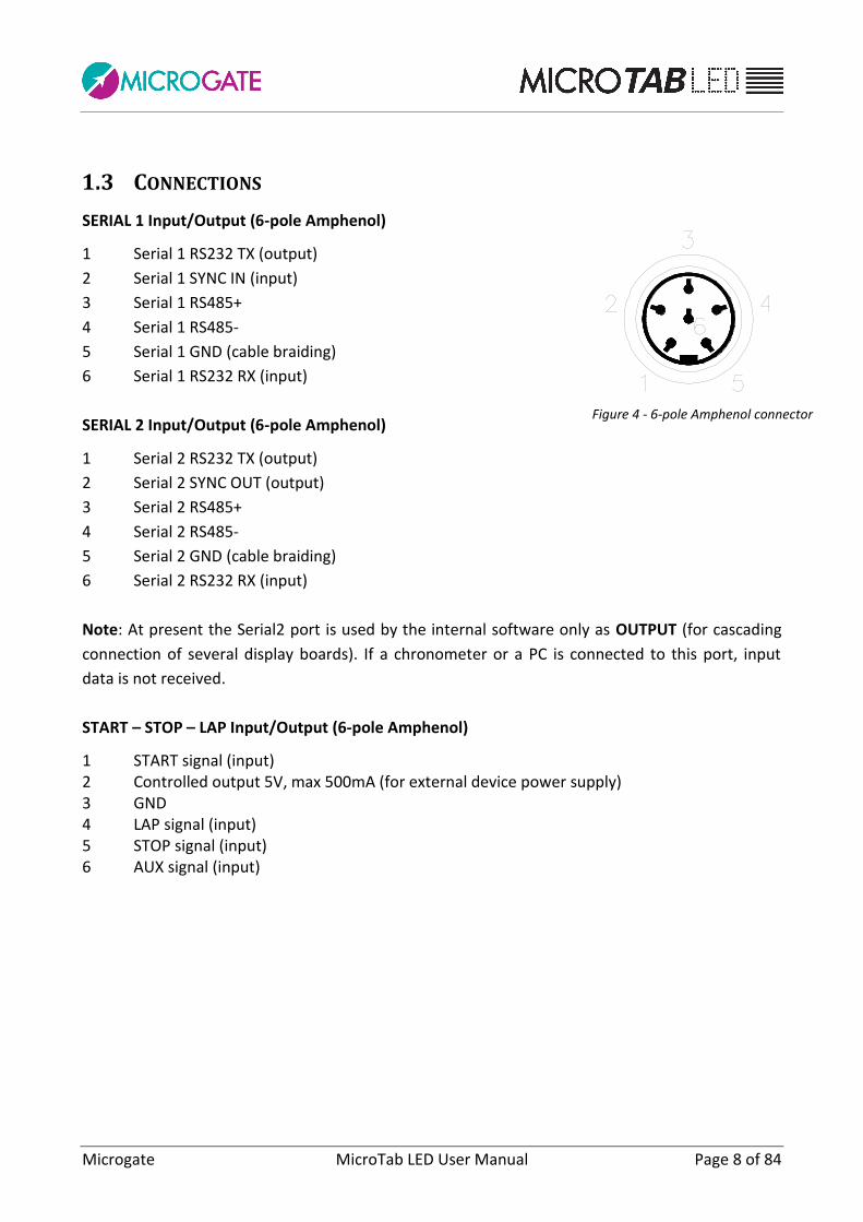
1.3 CONNECTIONS
SERIAL 1 Input/Output (6-pole Amphenol)
1 Serial 1 RS232 TX (output)
2 Serial 1 SYNC IN (input)
3 Serial 1 RS485+
4 Serial 1 RS485-
5 Serial 1 GND (cable braiding)
6 Serial 1 RS232 RX (input)
SERIAL 2 Input/Output (6-pole Amphenol)
1 Serial 2 RS232 TX (output)
2 Serial 2 SYNC OUT (output)
3 Serial 2 RS485+
4 Serial 2 RS485-
5 Serial 2 GND (cable braiding)
6 Serial 2 RS232 RX (input)
Note: At present the Serial2 port is used by the internal software only as OUTPUT (for cascading
connection of several display boards). If a chronometer or a PC is connected to this port, input
data is not received.
START – STOP – LAP Input/Output (6-pole Amphenol)
1 START signal (input) 2 Controlled output 5V, max 500mA (for external device power supply) 3 GND 4 LAP signal (input) 5 STOP signal (input) 6 AUX signal (input)
Figure 4 - 6-pole Amphenol connector
Microgate MicroTab LED User Manual Page 9 of 84
1.4 POWER SUPPLY
Power can be supplied in three ways:
• Connecting the MicroTab display board to the Microgate network adapter (code
$ACC147). In this way it is possible to supply a mains graphic display board and to keep
the batteries (if used) charged at the same time. This guarantees perfect functioning
also when the mains power supply is interrupted. The $ACC147 network adapter
operates with an input of 50 or 60 Hz alternate current, within a range of 100 and 240
Volts.
• Using the internal batteries of the display board (optional module $ACC163); in this
case autonomy is usually over 8 hours of continuous functioning (depending on the
type of display used).
• Connecting the display board via the DC/DC 12/48V converter (optional module
$ACC174) to any direct current supply (stabilized or not) between 11 and 16 Volts,
which is able to supply at least 100W peak power and approximately 50W average
power. A (60Ah) car battery usually ensures more than 6 hours continuous operation
(depending on the used display type).
If 2 or more MicroTab display boards must be powered, the $ACC155 (200W, 48V, sealed) multiple
display board network adapter must be used.
IMPORTANT NOTICE: The $ACC147 network adapter is not suitable for outdoor use. Consequently
Microgate is not liable for any damages to persons or things caused by incorrect use of the
network adapter.
1.4.1.1 BATTERY CHARGING
To enter charging mode, press the green 'START MODIFY' button on the control panel for at least 2
seconds with the display board turned off and after having connected an external power source to
the SUPPLY connector. Charging can take up to 10 hours, depending on the initial battery level.
The charging process can be interrupted by pressing again the green 'START MODIFY' button on
the control panel for at least 2 seconds.
The more frequently lithium-ion polymer (Li-poly) batteries are charged, the longer the battery life
will be.
Microgate MicroTab LED User Manual Page 10 of 84
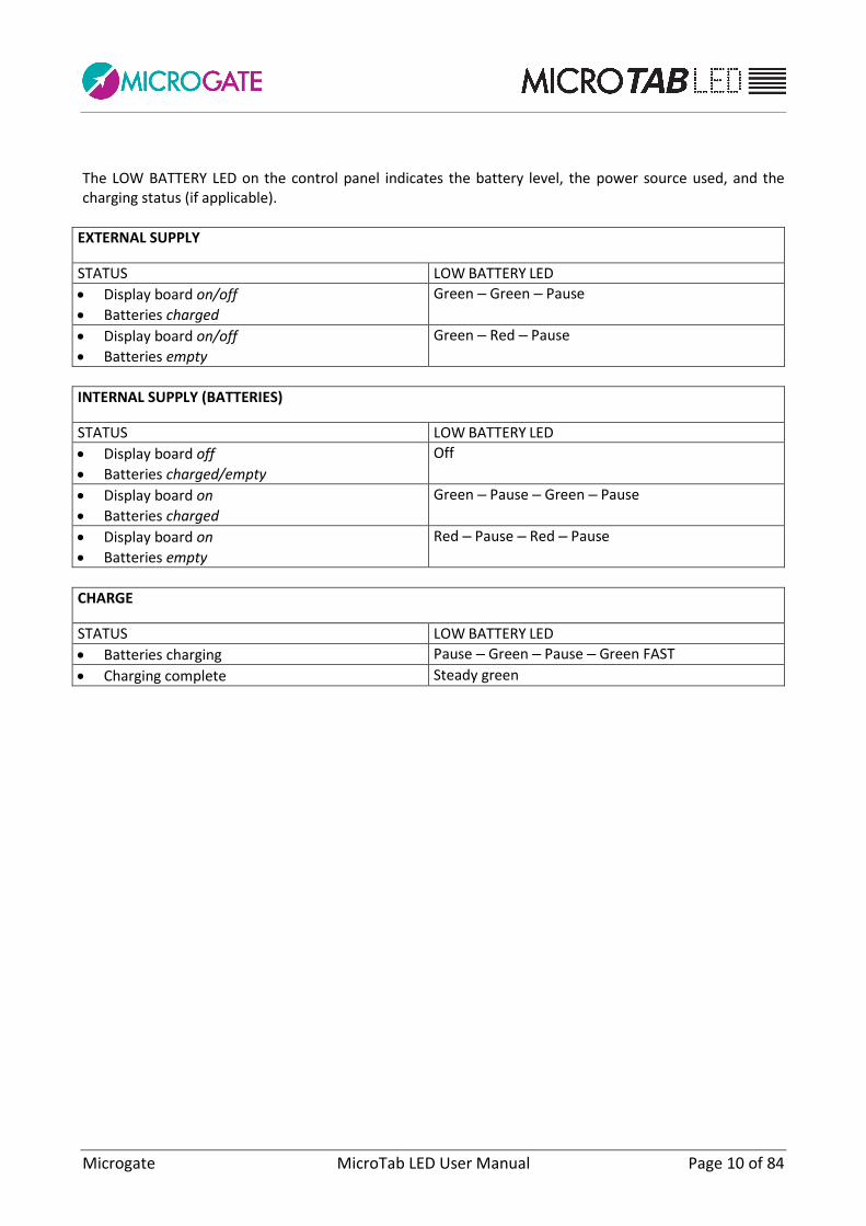
The LOW BATTERY LED on the control panel indicates the battery level, the power source used, and the charging status (if applicable).
EXTERNAL SUPPLY
STATUS LOW BATTERY LED
Display board on/off
Batteries charged
Green – Green – Pause
Display board on/off
Batteries empty
Green – Red – Pause
INTERNAL SUPPLY (BATTERIES)
STATUS LOW BATTERY LED
Display board off
Batteries charged/empty
Off
Display board on
Batteries charged
Green – Pause – Green – Pause
Display board on
Batteries empty
Red – Pause – Red – Pause
CHARGE
STATUS LOW BATTERY LED
Batteries charging Pause – Green – Pause – Green FAST
Charging complete Steady green
Microgate MicroTab LED User Manual Page 11 of 84
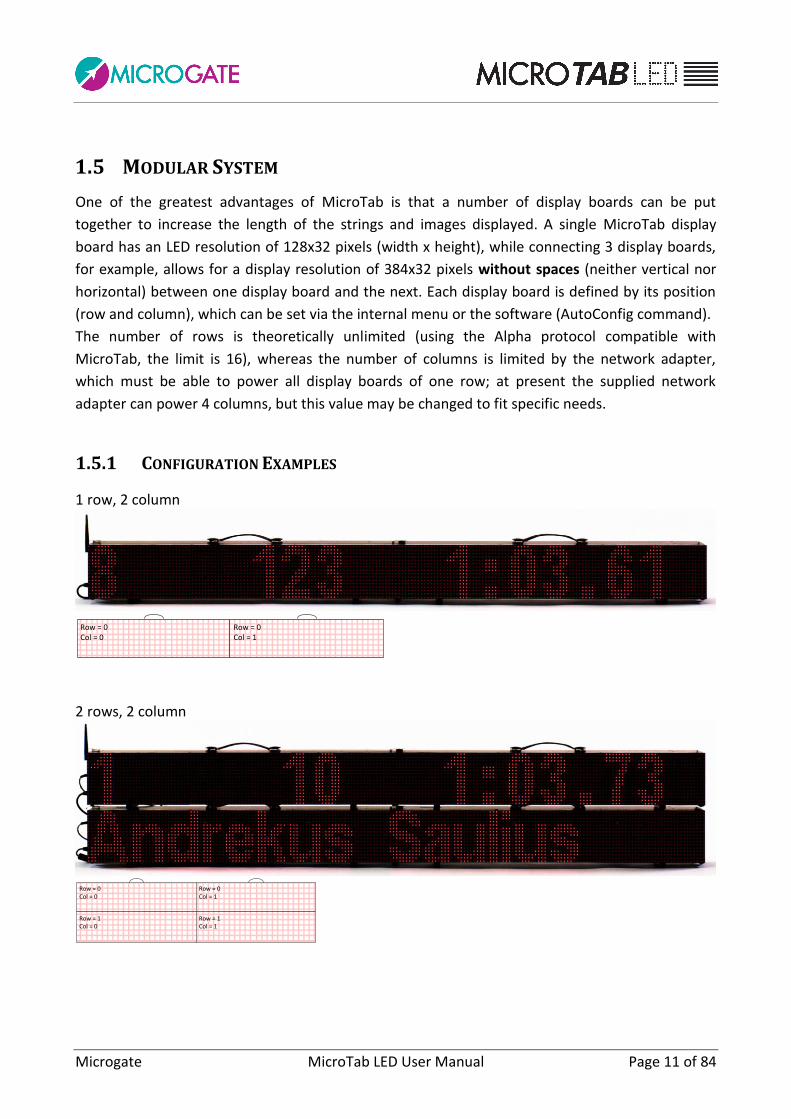
1.5 MODULAR SYSTEM
One of the greatest advantages of MicroTab is that a number of display boards can be put
together to increase the length of the strings and images displayed. A single MicroTab display
board has an LED resolution of 128x32 pixels (width x height), while connecting 3 display boards,
for example, allows for a display resolution of 384x32 pixels without spaces (neither vertical nor
horizontal) between one display board and the next. Each display board is defined by its position
(row and column), which can be set via the internal menu or the software (AutoConfig command).
The number of rows is theoretically unlimited (using the Alpha protocol compatible with
MicroTab, the limit is 16), whereas the number of columns is limited by the network adapter,
which must be able to power all display boards of one row; at present the supplied network
adapter can power 4 columns, but this value may be changed to fit specific needs.
1.5.1 CONFIGURATION EXAMPLES
1 row, 2 column
Row = 0Col = 0
Row = 0Col = 1
2 rows, 2 column
Row = 0Col = 0
Row = 0Col = 1
Row = 1Col = 0
Row = 1Col = 1

Microgate MicroTab LED User Manual Page 12 of 84
3 rows, 2 columns
Row = 0Col = 0
Row = 0Col = 1
Row = 1Col = 0
Row = 1Col = 1
Row = 2Col = 0
Row = 2Col = 1

Microgate MicroTab LED User Manual Page 13 of 84
1.5.2 ASSEMBLY
The assembly of a modular system is extremely simple. Put two display boards together and connect the Supply cable to its socket and the serial cable to the Serial1 connector.
Figure 5 - Cable connection
Insert the pins in the lower right corner of the rightmost display board into the dedicated slots of the previous display board.
Figure 6 - Inserting the pins

Microgate MicroTab LED User Manual Page 14 of 84
Hook the latch on the top using the screw on the top of the other display board.
Figure 7 - Hooking the latch
To carry out a connection of more than one row it is necessary to put the display boards one on top of the other, WITHOUT removing the feet or the handle.
Use the $CAB009 serial cable (not supplied, can be purchased separately) to connect the Serial2 connector of one display board with the Serial1 connector of the next display board (cascading connection; Serial 2 of row N must be connected to Serial1 of row N+1)

Microgate MicroTab LED User Manual Page 15 of 84
Figure 8 - Connection of lines
NOTE: BEFORE assembly, carry out the row and column configuration for each display board
(par.2.2.1, Row and Column Parameters). Alternatively, after assembly, using the Microgate
software or another third-party software implementing our protocol, use the AutoConfig
commands (par. 3.1.2).
Microgate MicroTab LED User Manual Page 16 of 84
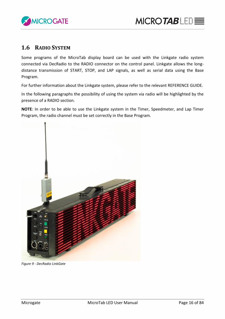
1.6 RADIO SYSTEM
Some programs of the MicroTab display board can be used with the Linkgate radio system
connected via DecRadio to the RADIO connector on the control panel. Linkgate allows the long-
distance transmission of START, STOP, and LAP signals, as well as serial data using the Base
Program.
For further information about the Linkgate system, please refer to the relevant REFERENCE GUIDE.
In the following paragraphs the possibility of using the system via radio will be highlighted by the
presence of a RADIO section.
NOTE: In order to be able to use the Linkgate system in the Timer, Speedmeter, and Lap Timer
Program, the radio channel must be set correctly in the Base Program.
Figure 9 - DecRadio LinkGate

Microgate MicroTab LED User Manual Page 17 of 84
1.7 FIRMWARE UPDATING
Each time MicroTab is turned on, it displays the firmware version presently stored, usually with
the following syntax: x.y.z (major, minor, revision).
Figure 10 - Firmware version
The firmware can be updated downloading it from the SUPPORT section of the www.microgate.it
website.
Once downloaded the file, please follow the steps below:
Turn on the display board and wait until boot is complete.
Connect the USB cable (not supplied) from the display board to a USB port of your PC.
Launch the Updater program following the on-screen instructions. In particular, if the
software does not detect Active Sync (for Windows XP) or Windows Mobile Device Center
(Vista/Windows 7), it suggests a link for downloading and installing it.
Select the option 'Keep existing settings' to maintain all current settings; if you do not
select it, the default values are restored.
After a few minutes the display board is reset automatically displaying the number of the
new installed version.
Figure 11 – Updater Software

Microgate MicroTab LED User Manual Page 18 of 84
1.8 HARDWARE RESET
If the display board stops responding to commands (e.g. entering the Setup menu as described in
par. 2.1), a Strong Reset can be carried out choosing to reset all values to the default parameters
(Factory Settings).
The steps to carry out are the following:
Turn off the display board by pressing the Power (Off) button.
Press simultaneously the START-MODIFY and LAP-SETUP buttons to turn on the display board
(Power -> On)
During the first boot phase, when the first 4 LEDs (2x2) in the upper left corner are blinking,
keep the two buttons pressed.
When the blinking LEDs are 6 (3 x 2) release the two buttons.
After a few moments the software asks if you want to restore the factory settings (Reset
Setting? Yellow=Yes) or use the stored settings. Press LAP-SETUP to reset all values
to the initial conditions.

Microgate MicroTab LED User Manual Page 19 of 84
1.9 BRIGHTNESS SENSOR
Display board LED brightness can be set manually (from the menu or software) or assessed
automatically depending on the ambient light detected by the brightness sensor in the upper left
corner (4th row, 5th column). There are other sensors for each 32x32 LED area, but only the one in
the upper left corner is used for active control.
The minimum-maximum brightness values range from 1 to 100%, although in the default settings
60 is the maximum value. This means that the maximum brightness value that can be set
automatically by the sensor is 60. Normally this value is enough even in case of strong light or
sunny days. If you want to increase brightness (which causes higher power and battery
consumption), set 1 – 100 as minimum and maximum value so that the sensor can set higher
values. Of course it is possible to set Brightness Type = Manual (instead of Automatic) and to
choose a fixed brightness level (see par. 2.1)
Figure 12 – Brightness sensor

Microgate MicroTab LED User Manual Page 20 of 84
2 INTERNAL PROGRAMS
Besides the 'Base Program', which waits for PC or chronometer commands and displays the
received information, MicroTab LED display boards also have a series of internal programs for
various timing needs.
The programs available at the time of printing this guide are:
Base Program Waits for commands via serial cable or IP (Ethernet/WiFi)
Internal Program Automatically executes the stored program.
Timer Works like a normal 1/100 second precision chronometer.
Speedmeter Measures the speed based on any length.
Countdown Displays various countdown types.
Clock Displays the time of the internal clock of the display board.
Date & Clock Displays date and time of the internal clock of the display board.
Lap Timer Timing of lap times.
Test Pixel Checks that the LEDs work correctly.
Self Timer Manages a Self-Timing course (with token machine and optional printer).
Self Timer Parallel Manages a Self-Timing parallel course.
OSM6 Connection with Omega OSM6 chronometer.
Powertime Connection with Powertime chronometer.
Alge Connection with Alge chronometer.
Omega Connection with Omega chronometer.
Stalker Connection with Stalker speedmeter
Jugs Connection with Jugs speedmeter
Athletic Program for cycle-racing and athletics tracks.
To change program follow these steps:
Keep the YELLOW LAP-SETUP button pressed for at least 3 seconds.
The currently selected program is displayed.
Press the GREEN START-MODIFY button to scroll down the above-stated program list.
Once the desired program has been reached, press the LAP-SETUP button to confirm.
Depending on the chosen program, further settings may be required or the program is
executed immediately.
Microgate MicroTab LED User Manual Page 21 of 84
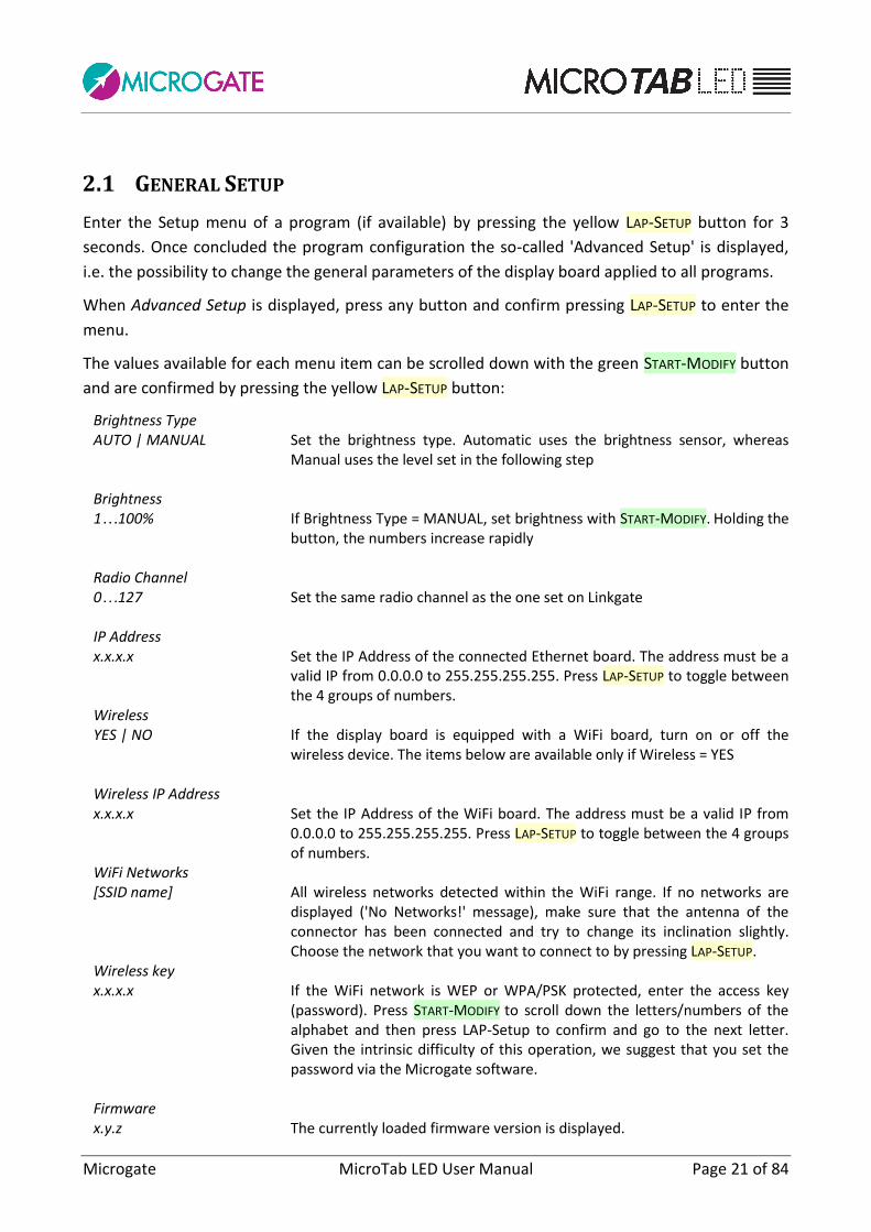
2.1 GENERAL SETUP
Enter the Setup menu of a program (if available) by pressing the yellow LAP-SETUP button for 3
seconds. Once concluded the program configuration the so-called 'Advanced Setup' is displayed,
i.e. the possibility to change the general parameters of the display board applied to all programs.
When Advanced Setup is displayed, press any button and confirm pressing LAP-SETUP to enter the
menu.
The values available for each menu item can be scrolled down with the green START-MODIFY button
and are confirmed by pressing the yellow LAP-SETUP button:
Brightness Type AUTO | MANUAL Set the brightness type. Automatic uses the brightness sensor, whereas
Manual uses the level set in the following step Brightness 1…100% If Brightness Type = MANUAL, set brightness with START-MODIFY. Holding the
button, the numbers increase rapidly Radio Channel 0…127 Set the same radio channel as the one set on Linkgate IP Address x.x.x.x Set the IP Address of the connected Ethernet board. The address must be a
valid IP from 0.0.0.0 to 255.255.255.255. Press LAP-SETUP to toggle between the 4 groups of numbers.
Wireless YES | NO If the display board is equipped with a WiFi board, turn on or off the
wireless device. The items below are available only if Wireless = YES Wireless IP Address x.x.x.x Set the IP Address of the WiFi board. The address must be a valid IP from
0.0.0.0 to 255.255.255.255. Press LAP-SETUP to toggle between the 4 groups of numbers.
WiFi Networks [SSID name] All wireless networks detected within the WiFi range. If no networks are
displayed ('No Networks!' message), make sure that the antenna of the connector has been connected and try to change its inclination slightly. Choose the network that you want to connect to by pressing LAP-SETUP.
Wireless key x.x.x.x If the WiFi network is WEP or WPA/PSK protected, enter the access key
(password). Press START-MODIFY to scroll down the letters/numbers of the alphabet and then press LAP-Setup to confirm and go to the next letter. Given the intrinsic difficulty of this operation, we suggest that you set the password via the Microgate software.
Firmware x.y.z The currently loaded firmware version is displayed.
Microgate MicroTab LED User Manual Page 22 of 84
Serial Number xxxxxxxxxxx The display board serial number is displayed. Press LAP-Setup to continue
and exit the Advanced Setup menu.

Microgate MicroTab LED User Manual Page 23 of 84
2.2 BASE PROGRAM
Selecting Base Program MicroTab can be controlled via the SERIAL 1 communication port, the
RADIO connector, the Ethernet port or the WiFi network (optional).
In par. 3 the commands which can be sent to the MicroTab display board are listed. We strongly
suggest to new users to exploit the versatile Microgate software to control MicroTab correctly,
instead of undertaking tedious direct programming attempts.
NOTE: the commands described as 'priority' or 'non-priority' (or 'strong' and 'weak') are to be
interpreted as priority or not with respect to the pause command, e.g. a 'weak reset' given after a
pause command is carried out only after the pause. On the contrary, a 'strong reset' command is
carried out unconditionally.
RADIO: Using the system via Linkgate radio in the Base Program, the transmitted radio signal type
must be different from the one of other programs and it is advisable not to exceed the
transmitter/receiver range of 150 m.
Figure 13
As shown in Figure 1, DecRadio is connected directly to the display board RADIO connector,
whereas EncRadio is connected to a PC, REI2, or RACETIME2 via relevant cable (CAB073 for PC,
CAB075 for RACETIME2, and CAB071 with CONNECTION BOX for REI2). To start communication,
simultaneously press the 2nd button and the button on EncRadio. Data will be transmitted at a
speed of 1200 bit/s.
DE
CR
AD
IO
EN
CR
AD
IO
INGRESSO RADIOBOCCOLA
BLU
BOCCOLA
NERA
uTAB
A R
EI2
, R
AC
ET
IME
2 O
PC
CAB0xx
TASTO MODEM

Microgate MicroTab LED User Manual Page 24 of 84
2.2.1 SETUP
Keep the LAP-SETUP pressed for at least 2 seconds to enter the Setup. Press START-MODIFY to change the displayed values.
Advanced Setup ? Press any key to continue. Yellow = Yes Press LAP-SETUP to enter the general setup (see par. 2.1) Green = No Press START-MODIFY to scroll the setup of the current program Font Regular|Narrow Set the default font (normal or narrow) Press LAP-SETUP Row 0...15 Set the row address (0 = first row) Press LAP-SETUP Column 0...3 Set column address (0 = first column) Press LAP-SETUP X Offset 0...384 Set the number of X Offset LEDs. All commands (with the ALPHA protocol)
will be shifted to the left by a certain amount of LEDs. Press LAP-SETUP Baud 1200…230400|RADIO Set the speed of the serial port applying one of the default values ('1200',
'2400', '4800', '9600', '19200', '38400', '38400', '57600', '115200', '230400', 'RADIO'). Specifying 'RADIO' communication via modem with Linkgate is activated.
Press LAP-SETUP Green to Default Press the green START-MODIFY button to reset the display board to the
default values, or press the yellow LAP-SETUP button to accept the entered values.
Microgate MicroTab LED User Manual Page 25 of 84
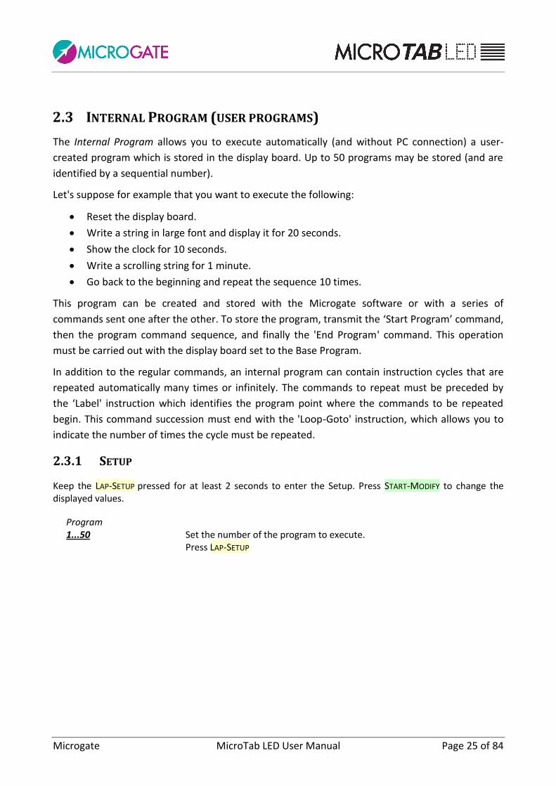
2.3 INTERNAL PROGRAM (USER PROGRAMS)
The Internal Program allows you to execute automatically (and without PC connection) a user-
created program which is stored in the display board. Up to 50 programs may be stored (and are
identified by a sequential number).
Let's suppose for example that you want to execute the following:
Reset the display board.
Write a string in large font and display it for 20 seconds.
Show the clock for 10 seconds.
Write a scrolling string for 1 minute.
Go back to the beginning and repeat the sequence 10 times.
This program can be created and stored with the Microgate software or with a series of
commands sent one after the other. To store the program, transmit the ‘Start Program’ command,
then the program command sequence, and finally the 'End Program' command. This operation
must be carried out with the display board set to the Base Program.
In addition to the regular commands, an internal program can contain instruction cycles that are
repeated automatically many times or infinitely. The commands to repeat must be preceded by
the ‘Label' instruction which identifies the program point where the commands to be repeated
begin. This command succession must end with the 'Loop-Goto' instruction, which allows you to
indicate the number of times the cycle must be repeated.
2.3.1 SETUP
Keep the LAP-SETUP pressed for at least 2 seconds to enter the Setup. Press START-MODIFY to change the displayed values.
Program 1...50 Set the number of the program to execute. Press LAP-SETUP

Microgate MicroTab LED User Manual Page 26 of 84
2.4 TIMER (CHRONOMETER)
In this mode MicroTab works as a typical 1/100 second precision chronometer.
• Pressing Start (manual, from input or via radio) the chronometer begins to count.
• With Lap (manual, from input or via radio) the chronometer displays an intermediate
time for 5 seconds.
• The chronometer is stopped using the manual Start/Stop or via radio.
• At this point it is possible to reset the chronometer with a further Lap.
Without reset the chronometer starts from the displayed value.
If the AutoReset time has been set, after each Stop (or manual Start) the chronometer is reset
after a given amount of time.
RADIO: The Timer program can be used also with a Linkgate radio system once the radio channel
has been set correctly. The MicroTab display board works also with START, LAP, and STOP signals
from Linkgate.
2.4.1 SETUP
Keep the LAP-SETUP pressed for at least 2 seconds to enter the Setup. Press START-MODIFY to change the displayed values.
Configuration Normal | Over 24H | Until 24H Set the desired mode: Normal = the chronometer starts from 0:00 Over 24H = the chronometer continues infinitely and after 24h displays
time as 24:00:01 Until 24H = the chronometer stops after 24h.00.00 Press LAP-SETUP Advanced Setup ? Press any key to continue. Yellow = Yes Press LAP-SETUP to enter the general setup (see par. 2.1) Green = No Press START-MODIFY to scroll the setup of the current program Set Starttime HH= 0 Set the hours Press LAP-SETUP Set Starttime MM= 0 Set the minutes Press LAP-SETUP Set Starttime SS= 0 Set the seconds Press LAP-SETUP

Microgate MicroTab LED User Manual Page 27 of 84
Set Starttime mm= 0 Set the thousandths of a second Press LAP-SETUP Autoreset Time= 0 Set the automatic Reset time (in seconds). After a stop command and
when the above-stated time has passed, the chronometer is reset to zero. An invalid (zero) time disables the Autoreset function.
Press LAP-SETUP Start – Stop The Start button is used at start and finish Start – Start The Start button is used only at start The chronometer is stopped and shows the preset time, ready to start.
Microgate MicroTab LED User Manual Page 28 of 84
2.5 SPEEDMETER
This program allows you to measure the speed on the basis of any given length. Speed is
calculated on the basis of the time interval between two Lap-Stop from input or via radio or
manual Lap-Starts pulses. Therefore you only need to place two photocells at the desired distance
and connect them to the Lap and Stop inputs. If the bidirectional mode has been set, the
measurement base can be used in both directions. It is advisable to use the bidirectional mode
only if absolutely necessary. The system is able to manage up to 20 simultaneous transits in the
measurement base.
If a delay has been set for the activation of the stored program (see 'Setup' below), when the time
has passed after the last measurement, the display of the sequence stored as program is
automatically started. This auxiliary function allows you to automatically display information or
advertising during the pauses between transits.
NOTE: Obviously, the precision of speed measurement depends on the accuracy of time
measurement on the measurement base. To ensure a precision of 0.025 Km/h up to speeds of 130
km/h, just place the photocells at least 10 m apart from each other (using MICROGATE photocells).
Increasing the distance increases the measurement accuracy.
RADIO: In addition to giving the manual LAP and START or input LAP or STOP signals, a Linkgate
radio system can be used. In this case the following instructions are available:
Use of 2 Polifemo photocells and 2 EncRadios. The signal of the first EncRadio must be set on LAP
(any), and that of the second on STOP.

Microgate MicroTab LED User Manual Page 29 of 84
Figure 14
In the example shown in Figure 14, 2 Polifemos connected to EncRadio with Banana Cube have
been used.
It is important to point out that if the EncRadios have been set to LONG transmission signals, the
time for covering the length base cannot be less than 3 seconds, whereas using SHORT signals the
time cannot be less than 1 second.
Figure 15
Use of 2 Polifemo photocells and 1 EncRadio. The first photocell must be connected (2-meter
CAB050 cable or 20 meter CAB048 cables) to the Red and Black banana jacks of the Encradio and
the second to the Green and Black banana jacks. The rotating selector for the selection of the
signal on the Encradio must be set to LAP E. With this option it is not possible to exploit the
bidirectionality of the system or to have more than one competitor in the measurement base.
DE
CR
AD
IO
INGRESSO RADIO
uTAB
POLIFEMO
EN
CR
AD
IO (
Sto
p)
BANANA CUBE
POLIFEMO
EN
CR
AD
IO (
Lap
qu
als
iasi)
BANANA CUBE
DE
CR
AD
IO
INGRESSO RADIO
uTAB
POLIFEMO
EN
CR
AD
IO
BANANA VERDE IN
BOCCOLA ROSSA
BANANA NERA IN
BOCCOLA NERA
BANANA VERDE IN
BOCCOLA VERDE
BANANA NERA IN
BOCCOLA NERA
BANANA VERDE IN
BOCCOLA VERDE
BANANA NERA IN
BOCCOLA NERA
CA
B048 o
CA
B050
POLIFEMO
BANANA VERDE IN
BOCCOLA VERDE
BANANA NERA IN
BOCCOLA NERA
Microgate MicroTab LED User Manual Page 30 of 84
2.5.1 SETUP
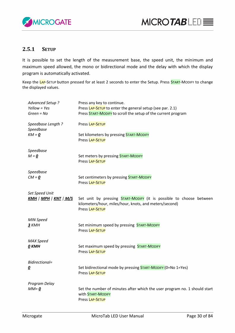
It is possible to set the length of the measurement base, the speed unit, the minimum and
maximum speed allowed, the mono or bidirectional mode and the delay with which the display
program is automatically activated.
Keep the LAP-SETUP button pressed for at least 2 seconds to enter the Setup. Press START-MODIFY to change the displayed values.
Advanced Setup ? Press any key to continue. Yellow = Yes Press LAP-SETUP to enter the general setup (see par. 2.1) Green = No Press START-MODIFY to scroll the setup of the current program Speedbase Length ? Press LAP-SETUP Speedbase KM = 0 Set kilometers by pressing START-MODIFY Press LAP-SETUP Speedbase M = 0 Set meters by pressing START-MODIFY Press LAP-SETUP Speedbase CM = 0 Set centimeters by pressing START-MODIFY Press LAP-SETUP Set Speed Unit KMH | MPH | KNT | M/S Set unit by pressing START-MODIFY (it is possible to choose between
kilometers/hour, miles/hour, knots, and meters/second) Press LAP-SETUP MIN Speed 3 KMH Set minimum speed by pressing START-MODIFY Press LAP-SETUP MAX Speed 0 KMH Set maximum speed by pressing START-MODIFY Press LAP-SETUP Bidirectional= 0 Set bidirectional mode by pressing START-MODIFY (0=No 1=Yes) Press LAP-SETUP Program Delay MM= 0 Set the number of minutes after which the user program no. 1 should start
with START-MODIFY Press LAP-SETUP

Microgate MicroTab LED User Manual Page 31 of 84
Program Delay SS= 0 Set the number of seconds after which the user program no. 1 should start
with START-MODIFY Press LAP-SETUP
When exiting the setup, the writing 'READY' is displayed and the program is ready for speed detection. NOTE: Minimum and Maximum speed refer to the measurement unit currently set.

Microgate MicroTab LED User Manual Page 32 of 84
2.6 COUNTDOWN
This program allows you to display various countdown types. After choosing the program you must indicate which one of the 3 types is to be used:
Configuration Start Time1| Start Time2| Time to zero Set mode by pressing START-MODIFY:
Press LAP-SETUP
2.6.1 START TIME 1
In this mode MicroTab simulates a start timer. The beeper is activated at -10 seconds, at -5, -4, -3, -2, -1, and 0 seconds from the set start time. Normally, the built-in beeper is too weak. It is advisable to connect the loudspeaker to the external socket on the side control panel. The start device (starting gate or other) should be connected to the START-STOP-LAP-INPUTS input. At each start the starting time (minutes, seconds and thousandths) and the deviation in minutes, seconds and thousandths relative to the scheduled starting time (with - for early start and + for delayed start) are displayed in sequence. NOTE: The first start is given at the first net minute after activation of the Countdown Program.
2.6.1.1 SETUP
The time intervals between successive starts, the green light time and the time displayed can be preset (so as to synchronize the internal clock with other devices, usually the main chronometer). The period between each start is set to 0 and the countdown from -10 seconds starts when the LAP-SETUP
key is pressed (or when the Lap input is activated). In this way the start sequence can be set manually. In this case deviation from the scheduled start time is neither displayed nor printed. Keep the LAP-SETUP pressed for at least 2 seconds to enter the Setup.
Cycle: MM= 0 Set the minutes between each start with START-MODIFY Press LAP-SETUP Cycle: SS= 30 Set the seconds between each start with START-MODIFY Press LAP-SETUP Greentime 6 Set the seconds of green light time and the other one with START-MODIFY Press LAP-SETUP Set Sync.Time HH = 10 Set the time with START-MODIFY Press LAP-SETUP Set Sync.Time MM = 44 Set the minutes with START-MODIFY Press LAP-SETUP Set Sync.Time

Microgate MicroTab LED User Manual Page 33 of 84
SS = 12 Set the seconds with START-MODIFY Press LAP-SETUP Set Sync.Time mm = 234 Set the thousandths with START-MODIFY Press LAP-SETUP
Now, if the time for synchronization is over, MicroTab waits for a START (from button or input) for synchronization and displays:
Set Sync.time 02:44:01 Start to Sync. Press START-MODIFY or send START signal from input.
NOTE: When setting the time for synchronization, MicroTab shows the time of first setting. If no value is modified, time is not changed and continues to run as if Setup had not been used. This makes it possible to edit the other parameters without losing synchronization.
2.6.2 START TIME 2
The way this program functions is similar to that of the previous program. In this case however, at each start the starting time (minutes, seconds and thousandths) and the deviation in minutes, seconds and thousandths relative to the scheduled starting time (with - for early start and + for delayed start) are displayed in sequence.

Microgate MicroTab LED User Manual Page 34 of 84
2.6.3 TIME TO ZERO
In this case the countdown starts from the time set by the user and stops at zero, with the last five seconds signaled with a beep.
2.6.3.1 SETUP
Cycle: HH = 0 Set the hours between each start with START-MODIFY Press LAP-SETUP Cycle: MM = 0 Set the minutes between each start with START-MODIFY Press LAP-SETUP Cycle: SS = 0 Set the seconds with START-MODIFY Press LAP-SETUP Cycle: mm = 0 Set the thousandths between each start with START-MODIFY Press LAP-SETUP Greentime 6 Set the seconds of green light time and the other one with START-MODIFY Press LAP-SETUP One cycle | Repeat Cycle Press START-MODIFY to set one countdown or continuous countdown
repetitions.

Microgate MicroTab LED User Manual Page 35 of 84
2.7 CLOCK
This program allows you to display the time of the internal MicroTab clock.
2.7.1 SETUP
It is possible to set the date and time of the internal clock. NOTE: When setting the time, MicroTabLED shows the time of first setting. If no value is modified, time is not changed and continues to run as if Setup had not been used. Keep the LAP-SETUP button pressed for at least 2 seconds to enter the Setup. Press START-MODIFY to change the displayed values.
Configuration HH:MM:SS | HH:MM Set display mode with START-MODIFY Advanced Setup ? Press any key to continue. Yellow = Yes Press LAP-SETUP to enter the general setup (see par. 2.1) Green = No Press START-MODIFY to scroll the setup of the current program Set R.T. Date Day = 13 Set the day of the month with START-MODIFY Press LAP-SETUP Set R.T. Date daynum = 3 Set the week day with START-MODIFY (1 Sunday, 2 Monday, ..., 7 Saturday) Press LAP-SETUP Set R.T. Date month = 7 Set the month with START-MODIFY (1 January, 2 February, …, 12 December) Press LAP-SETUP Set R.T. Clock HH = 0 Set the time with START-MODIFY Press LAP-SETUP Set R.T. Clock MM = 0 Set the minutes with START-MODIFY Press LAP-SETUP Set R.T. Clock SS = 0 Set the seconds with START-MODIFY Press LAP-SETUP
Microgate MicroTab LED User Manual Page 36 of 84
2.8 DATE & CLOCK
This mode allows you to display the time of the internal MicroTabLED clock.
2.8.1 SETUP
It is possible to set the date and time of the internal clock. The steps are the same as in the Clock Program (see par. 2.7.1).

Microgate MicroTab LED User Manual Page 37 of 84
2.9 LAP TIMER
The Lap Timer program allows you to time lap times. At each Start or Stop pulse (indifferently) the chronometer detects the time from the previous impulse and restarts automatically from zero. Time continues to be displayed for 8 seconds, and then the running time appears again. The input and Lap key reset the chronometer to zero. RADIO: As well as giving the manual or input START, STOP, and LAP signals, a Linkgate radio system can be used (after correctly setting the radio channel in the General Setup).
2.9.1 SETUP
It is possible to set the starting and the deactivation time of inputs after a pulse (hold-off time). Keep the LAP-SETUP button pressed for at least 2 seconds to enter the Setup. Press START-MODIFY to change the displayed values.
Advanced Setup ? Press any key to continue. Yellow = Yes Press LAP-SETUP to enter the general setup (see par. 2.1) Green = No Press START-MODIFY to scroll the setup of the current program Start Time HH = 0 Set the time with START-MODIFY Press LAP-SETUP Start Time MM = 0 Set the minutes with START-MODIFY Press LAP-SETUP Start Time SS = 0 Set the seconds with START-MODIFY Press LAP-SETUP Start Time mm = 0 Set the thousandths with START-MODIFY Press LAP-SETUP Autoreset Time= 0 Set the automatic Reset time (in seconds). After a stop command and when
the above-stated time has passed, the chronometer is reset to zero. An invalid (zero) time disables the Autoreset function.
Press LAP-SETUP Holdoff SS = 0 Set the seconds with START-MODIFY Press LAP-SETUP

Microgate MicroTab LED User Manual Page 38 of 84
Holdoff Time mm = 10 Set the thousandths with START-MODIFY Press LAP-SETUP
Microgate MicroTab LED User Manual Page 39 of 84
2.10 TEST PIXEL
The Test Pixel program is used to check the correct functioning of LEDs: the display board turns all
LEDs on and off for a certain number of times. If an LED does not turn on, please contact our
technical support.
Microgate MicroTab LED User Manual Page 40 of 84
2.11 SELF TIMER AND PARALLEL SELF TIMER
The programs are described in the guide supplied with the optional 'Self Timing LED' module.

Microgate MicroTab LED User Manual Page 41 of 84
2.12 OSM6
This program allows you to use the display board together with an Omega OSM6 chronometer.
2.12.1 SETUP
Keep the LAP-SETUP button pressed for at least 2 seconds to enter the Setup. Press START-MODIFY to change the displayed values.
Configuration 0...15 Set the display mode Press LAP-SETUP

Microgate MicroTab LED User Manual Page 42 of 84
2.13 POWERTIME
This program allows you to use the display board together with a Powertime chronometer.

Microgate MicroTab LED User Manual Page 43 of 84
2.14 ALGE
This program allows you to use the display board together with an Alge chronometer.
2.14.1 SETUP
Keep the LAP-SETUP button pressed for at least 2 seconds to enter the Setup. Press START-MODIFY to change the displayed values.
Configuration "MM:SS.DCM" | "HH:MM:SS" | "H:MM:SS.D" | "NNN PP" | "NNN PP MM:SS.DCM" | "NNN PP H:MM:SS.DC" | "NNN PP HH:MM:SS.D","NNN PP HH:MM:SS" | "MMSS.DCM" | "HHMMSS" | "HMMSS.D" | "NNN M:SS.DC" | "NNN MM:SS.D" | "NNN M:SS.DC" Set the display mode.
2.14.2 NOTE FOR THE CONNECTION OF CHRONOMETERS
ALGE CHRONOMETERS Chronometer Display board 3 – GND 5 – GND 5 – Serial OUT 6 – Serial IN

Microgate MicroTab LED User Manual Page 44 of 84
2.15 OMEGA
This program allows you to use the display board together with an Omega/Longines 5005/Ares
chronometer.
2.15.1 SETUP
Keep the LAP-SETUP button pressed for at least 2 seconds to enter the Setup. Press START-MODIFY to change the displayed values.
Configuration 0...15 Set the display mode Press LAP-SETUP Row 0...15 Set the row address Press LAP-SETUP CONFIGURATION = 0 Compatible with the following programs: ML 582 (Mass Sports), ML590 (Road Cycling), ML584 (Horse Racing), etc. It makes it possible to display the running or final time (in the format minutes, seconds, and tenths-hundredths-thousandths) and also the number and position. CONFIGURATION = 1 Compatible with the following programs: ML 582 (Mass Sport), ML590 (Road Cycling), ML584 (Horse Riding), etc. Similar to the previous program. The time is displayed in the format hours-minutes, seconds-tenths. CONFIGURATION = 2 Compatible with ML programs. Similar to the previous program. The time is displayed in the format hours-minutes, seconds. CONFIGURATION = 3 Compatible with the following programs: ML 582 (Mass Sports), ML590 (Road Cycling), ML584 (Horse Riding), etc. Displays only number and position. CONFIGURATION = 4 Compatible with the ML 582 (Mass Sports) program. Displays number and position in 4-digit format. CONFIGURATION = 5 Compatible with the ML 683 (Car-Motorcycle) program. Displays the lap time (LAP) CONFIGURATION = 6 Compatible with the ML 683 (Car-Motorbike) program. Displays the speed in kilometers/hour.

Microgate MicroTab LED User Manual Page 45 of 84
CONFIGURATION = 7 Compatible with the ML 683 (Car-Motorcycle) program. Displays the speed in miles/hour. CONFIGURATION = 8 Compatible with the following programs: ML 582 (Mass Sports), ML 590 (Road Cycling), ML552/553 (Downhill and Cross-Country Skiing), ML 597 (Horse Racing), ML 566 (Track Skating). Displays the day time. CONFIGURATION = 9 Compatible with ML 566 (Track Skating) programs. Displays time, number and position of competitor B. CONFIGURATION = 10 Compatible with ML 566 (Track Skating) programs. Displays time, number and position of the leading competitor. CONFIGURATION = 11 Compatible with ML 566 (Track Skating) programs. Displays the lap time of competitor A. CONFIGURATION = 12 Compatible with ML 566 (Track Skating) programs. Displays the lap time of competitor B. CONFIGURATION = 13 Compatible with ML 566 (Track Skating) programs. Displays the number and 'status' (in/out) of competitor A and B. CONFIGURATION = 14 Compatible with ML 566 (Track Skating) programs. Displays the number and missing laps for competitor A and B.
2.15.2 NOTE FOR THE CONNECTION OF CHRONOMETERS
OMEGA/LONGINES 5005 CHRONOMETERS Chronometer Display board 4 – TX+ 5 – GND 3 – TX- 6 – Serial IN

Microgate MicroTab LED User Manual Page 46 of 84
2.16 STALKER
This program allows you to use the display board together with Stalker speed radars.
2.16.1 SETUP
Keep the LAP-SETUP button pressed for at least 2 seconds to enter the Setup. Press START-MODIFY to change the displayed values.
Baud 1200…230400|RADIO Set the speed of the serial port applying one of the default values ('1200',
'2400', '4800', '9600', '19200', '38400', '38400', '57600', '115200', '230400', 'RADIO'). Specifying 'RADIO' communication via modem with Linkgate is activated.
Press LAP-SETUP Set Speed Unit KMH | MPH | KNT | M/S Set unit by pressing START-MODIFY (it is possible to choose between
kilometers/hour, miles/hour, knots, and meters/second) Press LAP-SETUP

Microgate MicroTab LED User Manual Page 47 of 84
2.17 JUGS
This program allows you to use the display board together with Jugs speed radar gun.
2.17.1 SETUP
Keep the LAP-SETUP button pressed for at least 2 seconds to enter the Setup. Press START-MODIFY to change the displayed values.
Baud 1200…230400|RADIO Set the speed of the serial port applying one of the default values ('1200',
'2400', '4800', '9600', '19200', '38400', '38400', '57600', '115200', '230400', 'RADIO'). Specifying 'RADIO' communication via modem with Linkgate is activated.
Press LAP-SETUP Set Speed Unit KMH | MPH | KNT | M/S Set unit by pressing START-MODIFY (it is possible to choose between
kilometers/hour, miles/hour, knots, and meters/second) Press LAP-SETUP

Microgate MicroTab LED User Manual Page 48 of 84
2.18 ATHLETIC
This program has been studied for managing base information for track-and-field competitions. After choosing the program you must indicate which one of the 3 types is to be used:
2.18.1.1 SETUP
Keep the LAP-SETUP button pressed for at least 2 seconds to enter the Setup. Press START-MODIFY to change the displayed values.
Configuration Counter| Countdown| Wind Set the mode with START-MODIFY:
Press LAP-SETUP
2.18.2 COUNTER
Pressing the green START key, the number of laps increases by one unit. Pressing the yellow RESET
key, the number of laps decreases by one unit. After reaching the maximum lap number (999) the
value is reset to 0.
2.18.3 COUNTDOWN
Pressing the green START key, the countdown starts. To stop the chronometer just press the green
START key and, to restart it, press the green START key again. The yellow RESET key resets the
countdown. When the set time is finished, the display board displays the writing ‘OUT’. To go back
to the initial condition just press the yellow RESET key.
2.18.3.1 SETUP
Keep the LAP-SETUP button pressed for at least 2 seconds to enter the Setup. Press START-MODIFY to change the displayed values.
MM 0 Set the minutes of countdown start time. Press LAP-SETUP SS 30 Set the seconds of countdown start time. Press LAP-SETUP

Microgate MicroTab LED User Manual Page 49 of 84
2.18.4 WIND
The Wind program allows you to display data received from the Gill anemometer. The
anemometer must be connected with a cable to Serial 1.
2.18.4.1 SETUP
Keep the LAP-SETUP button pressed for at least 2 seconds to enter the Setup. Press START-MODIFY to change the displayed values.
Reset = 5 Set the number of seconds after which the display board deletes the
displayed speed. Press LAP-SETUP

Microgate MicroTab LED User Manual Page 50 of 84
3 TRANSMISSION PROTOCOL
Using 'Base Program' (see par. 2.2) it is possible to send commands to the display board or using
the serial port (set by default to 9600 baud, 8 bit, No parity, 1 stop bit) or a TCP/IP socket via
connected Ethernet or via WiFi (by default the Ethernet port listens to the IP address
192.168.0.123, port 21967, whereas the WiFi board listens to the IP address 192.168.0.124, port
21968).
All display boards of the MicroLED family use the same protocols of the MicroPIX family, more
specifically the original MicroTAB and the specialized MicroGraph protocol.
With the Test Protocol (ALPHA) (kept to ensure compatibility with older 'character' display boards
and all those devices using this protocol) elements are positioned by ROW and COLUMN, where
the row is identified by a character (from ‘A’ to ‘Q’, ‘ ‘ space = all) and the column by an integer
from 0 to 99.
Conventionally, in graphical and LED display boards, a column corresponds to the number of dots
(pixels or LEDs) composing the space character ' ' (ASCII 32, hex 20h) in the font set on the display
board. For example a column on the LED display boards set to the font 'medium proportional'
corresponds to 10 LEDs.
The font used to display information is the one set in the display board menu.
In the example below, the writing 'CIAO' in the font 'Medium' is positioned on row B, column 2
(the first column is zero) and the command to be given is the following:
Start Frame Row Command Column Data End Frame
ESC B ‘S’ 02 'CIAO' ETX + Chk
Row A
Row B
Col0 Col1 Col2 ...
Figure 16 - Writing positioning example with ALPHA protocol
It is clear that with this protocol positioning elements is discreted and not free for every single dot
(e.g. it is not possible to write in the center of the display board).

Microgate MicroTab LED User Manual Page 51 of 84
The Graphical Protocol (GRAPH), on the contrary, allows you to specify single dot positioning
using X and Y coordinates (string, date, clock, scrolling string, image, etc.) and to vary the font and
alignment using two properties (Font and Alignment).
In the above-stated example the writing can be positioned anywhere using the X Y coordinates of
its point of origin (in the top left corner, if the alignment is standard).
Therefore the command to be given is the following (write at position 45,8 in font 2=medium,
binary operation=0)
Start Frame Command X Y Bin Op. Font Data End Frame
ESC + @ ‘S’ 45 8 0 2 'CIAO' ETX + Chk
Figure 17 - Writing positioning example with GRAPH protocol
In the following table the main differences between the various display boards are listed.
Tech Name No. Dot X
No. Dot Y
Rows Cols Protocol COM ETH WIFI
PIX MicroTAB 56 11 16 9 ALPHA Y N N
PIX MicroGRAPH 90 24 16 9 ALPHA GRAPH
Y N N
LED MicroTAB 96 16 (16)* 4** ALPHA GRAPH
Y Y Y
LED MicroGRAPH 128 32 (16)* 4** ALPHA GRAPH
Y Y Y
* Theoretical limit -- not using the ALPHA protocol there is no limit.
** Limitation due to the use of one single power adapter per row.

Microgate MicroTab LED User Manual Page 52 of 84
3.1 TEXT FRAME (ALPHA PROTOCOL)
The text frame format is as follows:
Field Length Content Meaning
Start Frame 1 ESC (0x1B) Start command frame
Address 1 A...Q,‘ ’ Row identifier, blank for broadcast
Command 1 (Any) Command to send to the display board (see below)
Data Variable Variable Optional command data area
End Frame 1 ETX (0x03) End command frame
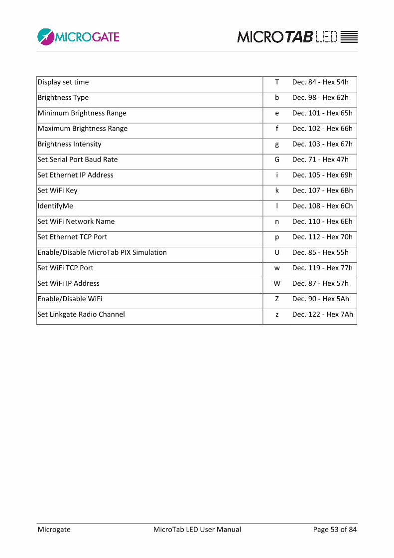
Checksum 1 Variable 7-bit checksum executed for the whole frame. In the table below the various commands are listed, which can be used in the Command field of the text record:
Command Code
Display Date A Dec. 65 - Hex 41h
Start Program B Dec. 66 - Hex 42h
Set time sensitive to Pause C Dec. 67 - Hex 43h
Set time insensitive to Pause c Dec. 99 - Hex 63h
Set Pause (suspends the execution of subsequent commands) D Dec. 68 - Hex 44h
Set Date d Dec. 100 - Hex 64h
Entry Point/Label for cycles E Dec. 69 - Hex 45h
End of Program K Dec. 75 - Hex 4Bh
Loop/Goto L Dec. 76 - Hex 4Ch
Set time internal clock (Real Time Clock) M Dec. 77 - Hex 4Dh
Display time internal clock (Real Time Clock) N Dec. 78 - Hex 4Eh
Write scrolling string O Dec. 79 - Hex 4Fh
Stop scrolling string o Dec. 111 - Hex 6Fh
Execute internal hardware program P Dec. 80 - Hex 50h
Self-Timing Printer Strings p Dec. 112 - Hex 70h
Weak display board Reset (sensitive to Pause) R Dec. 82 - Hex 52h
Strong display board Reset (sensitive to Pause) r Dec. 114 - Hex 72h
Write fix string S Dec. 83 - Hex 53h
Parameter Setup s Dec. 115 - Hex 73h
Microgate MicroTab LED User Manual Page 53 of 84
Display set time T Dec. 84 - Hex 54h
Brightness Type b Dec. 98 - Hex 62h
Minimum Brightness Range e Dec. 101 - Hex 65h
Maximum Brightness Range f Dec. 102 - Hex 66h
Brightness Intensity g Dec. 103 - Hex 67h
Set Serial Port Baud Rate G Dec. 71 - Hex 47h
Set Ethernet IP Address i Dec. 105 - Hex 69h
Set WiFi Key k Dec. 107 - Hex 6Bh
IdentifyMe l Dec. 108 - Hex 6Ch
Set WiFi Network Name n Dec. 110 - Hex 6Eh
Set Ethernet TCP Port p Dec. 112 - Hex 70h
Enable/Disable MicroTab PIX Simulation U Dec. 85 - Hex 55h
Set WiFi TCP Port w Dec. 119 - Hex 77h
Set WiFi IP Address W Dec. 87 - Hex 57h
Enable/Disable WiFi Z Dec. 90 - Hex 5Ah
Set Linkgate Radio Channel z Dec. 122 - Hex 7Ah
Microgate MicroTab LED User Manual Page 54 of 84
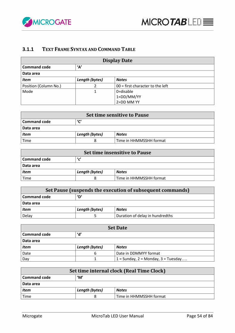
3.1.1 TEXT FRAME SYNTAX AND COMMAND TABLE
Display Date Command code ‘A’
Data area
Item Length (bytes) Notes
Position (Column No.) 2 00 = first character to the left
Mode 1 0=disable 1=DD/MM/YY 2=DD MM YY
Set time sensitive to Pause Command code ‘C’
Data area
Item Length (bytes) Notes
Time 8 Time in HHMMSSHH format
Set time insensitive to Pause Command code ‘c’
Data area
Item Length (bytes) Notes
Time 8 Time in HHMMSSHH format
Set Pause (suspends the execution of subsequent commands) Command code ‘D’
Data area
Item Length (bytes) Notes
Delay 5 Duration of delay in hundredths
Set Date Command code ‘d’
Data area
Item Length (bytes) Notes
Date 6 Date in DDMMYY format
Day 1 1 = Sunday, 2 = Monday, 3 = Tuesday….
Set time internal clock (Real Time Clock) Command code ‘M’
Data area
Item Length (bytes) Notes
Time 8 Time in HHMMSSHH format
Microgate MicroTab LED User Manual Page 55 of 84
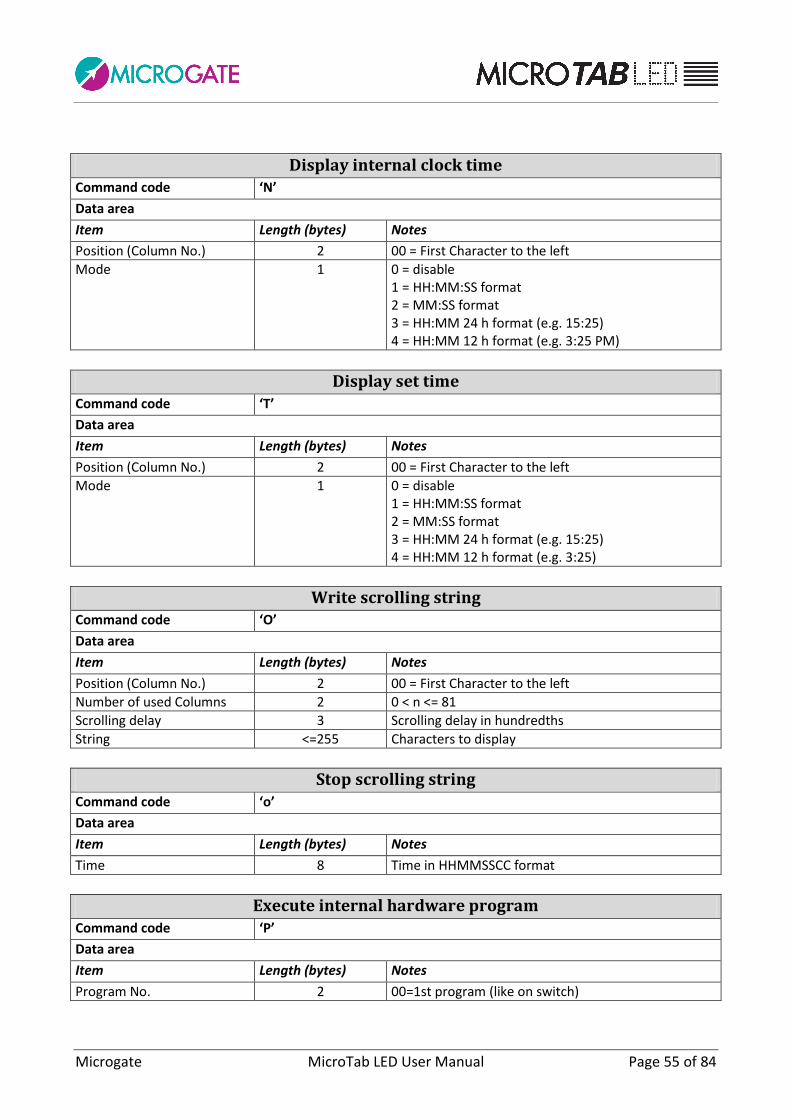
Display internal clock time Command code ‘N’
Data area
Item Length (bytes) Notes
Position (Column No.) 2 00 = First Character to the left
Mode 1 0 = disable 1 = HH:MM:SS format 2 = MM:SS format 3 = HH:MM 24 h format (e.g. 15:25) 4 = HH:MM 12 h format (e.g. 3:25 PM)
Display set time Command code ‘T’
Data area
Item Length (bytes) Notes
Position (Column No.) 2 00 = First Character to the left
Mode 1 0 = disable 1 = HH:MM:SS format 2 = MM:SS format 3 = HH:MM 24 h format (e.g. 15:25) 4 = HH:MM 12 h format (e.g. 3:25)
Write scrolling string Command code ‘O’
Data area
Item Length (bytes) Notes
Position (Column No.) 2 00 = First Character to the left
Number of used Columns 2 0 < n <= 81
Scrolling delay 3 Scrolling delay in hundredths
String <=255 Characters to display
Stop scrolling string Command code ‘o’
Data area
Item Length (bytes) Notes
Time 8 Time in HHMMSSCC format
Execute internal hardware program Command code ‘P’
Data area
Item Length (bytes) Notes
Program No. 2 00=1st program (like on switch)

Microgate MicroTab LED User Manual Page 56 of 84
Self-Timing Printer Strings Command code ‘p’
Data area
Item Length (bytes) Notes
Row 1 35 Characters of first string
Row 2 35 Characters of second string
Weak display board Reset (sensitive to Pause) Command code ‘R’
Data area
Item Length (bytes) Notes
None
Strong display board Reset (sensitive to Pause) Command code ‘r’
Data area
Item Length (bytes) Notes
None
Write fixed string Command code ‘S’
Data area
Item Length (bytes) Notes
Position (Column No.) 2 00 = First Character to the left
String <=81 Characters to display (with null terminator)
Brightness Type Command code ‘b’
Data area
Item Length (bytes) Notes
Type 1 0=Auto 1=Manual
Minimum Brightness Range Command code ‘e’
Data area
Item Length (bytes) Notes
Value Max 3 1 < n <= 100

Microgate MicroTab LED User Manual Page 57 of 84
Maximum Brightness Range Command code ‘f’
Data area
Item Length (bytes) Notes
Value Max 3 1 < n <= 100
Brightness Intensity Command code ‘g’
Data area
Item Length (bytes) Notes
Value Max 3 1 <= n <= 100 (applies only, if Brightness Type = Manual)
Set Serial Port Baud Rate Command code ‘G’
Data area
Item Length (bytes) Notes
Speed Max 6 '1200', '2400', '4800', '9600', '19200', '38400', '38400', '57600', '115200', '230400', 'RADIO'
Set Linkgate Radio Channel Command code ‘z’
Data area
Item Length (bytes) Notes
Channel Max 3 1 < n <= 127
Set Ethernet IP Address Command code ‘i’
Data area
Item Length (bytes) Notes
IP address Max 15 nnn.nnn.nnn.nnn (default = 192.168.0.123)
Set Ethernet TCP Port Command code ‘m’
Data area
Item Length (bytes) Notes
Port number Max 5 1 <= n <= 65535 (default = 21967)
Set WiFi IP Address Command code ‘W’
Data area
Item Length (bytes) Notes
IP address Max 15 nnn.nnn.nnn.nnn (default = 192.168.0.124)

Microgate MicroTab LED User Manual Page 58 of 84
Set WiFi TCP Port Command code ‘w’
Data area
Item Length (bytes) Notes
Port number Max 5 1 <= n <= 65535 (default = 21968)
Set WiFi Network Name Command code ‘n’
Data area
Item Length (bytes) Notes
SSID Name of WiFi SSID
Set WiFi Network Password Command code ‘k’
Data area
Item Length (bytes) Notes
Network Key Name of WiFi network WEP/WPA Key
Enable/Disable WiFi Network Command code ‘Z’
Data area
Item Length (bytes) Notes
Value 1 0=disable 1=enable
Enable/Disable MicroTab PIX Simulation Command code ‘U’
Data area
Item Length (bytes) Notes
Value 1 0=disable 1=enable
IdentifyMe (displays its Row/Column) Command code ‘l’
Data area
Item Length (bytes) Notes
None

Microgate MicroTab LED User Manual Page 59 of 84
Parameter Setup Command code ‘s’
Data area
Item Length (bytes) Notes
Sub-command 1 Alphabetical character (see below)
Parameter X See below
Parameter Setup Sub-commands
COUNTDOWN
A 999 Countdown Duration - 11<n500 (0=-10 sec., manual)
B 999 Valid Start Time - 0n500
O 999 Sub-program 0n2 (0='Start Time 1',. 1='Start Time 2', 2 = 'Time to Zero') SELFTIMING
C 999 Minimum time between 2 athletes - 10<n500
D 999 Maximum track time - 10<n500
I 999 Minimum track time - n0
E 999 Auto Program Time - 0n500
F 9999999 Speed base length in meters - 0n50000.00
L 999 Green Light Time - 0n600 (0=transit free – 600=always green)
M 999 Number of printer paper Line-feeds - 0n255 U 999 Unit of measurement (000=m/s 001=Kmh 002=mph 003=knt) SPEEDMETER
G 999 Auto Program Time - 0n500
H 9999999 Speed base length in meters - 0n50000.00 u 999 Unit of measurement (000=m/s 001=Kmh 002=mph 003=knt)
S 999 Maximum speed - n0
s 999 Minimum speed - n0
d 999 Bidirectionality 0n1 NORMAL
N 999 Column displayed first - 0n89
X 999 Row (0n15)
Y 999 Column (0n4) CHRONOLAP
I 9999999 Pulse hold-off time - 5n50000 TIMER
O 999 Subprogram 0n2 ('Normal', 'Over 24', 'Until 24H') DATE & CLOCK
O 999 Subprogram 0n2 ('HH:MM:SS', 'HH:MM') ALGE
O 999 Subprogram 0n13 ("MM:SS.DCM", "HH:MM:SS", "H:MM:SS.D", "NNN PP", "NNN PP MM:SS.DCM", "NNN PP H:MM:SS.DC", "NNN PP HH:MM:SS.D", "NNN PP HH:MM:SS", "MMSS.DCM", "HHMMSS", "HMMSS.D", "NNN M:SS.DC", "NNN MM:SS.D", "NNN M:SS.DC")
Microgate MicroTab LED User Manual Page 60 of 84
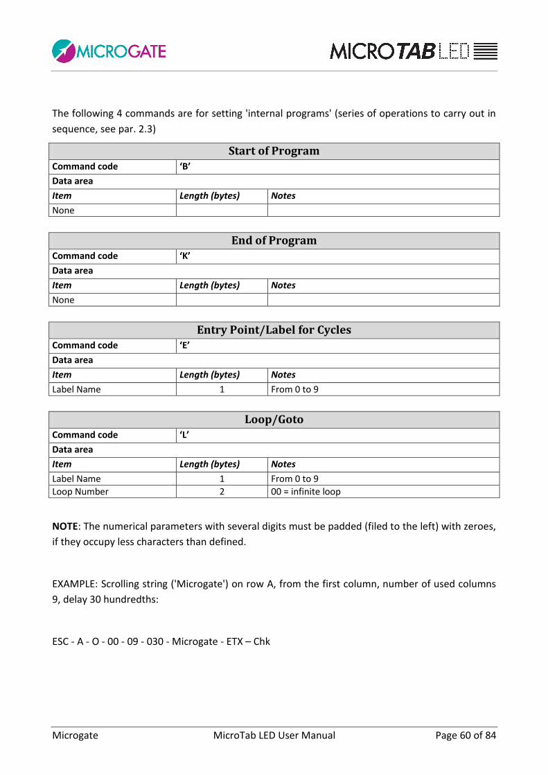
The following 4 commands are for setting 'internal programs' (series of operations to carry out in
sequence, see par. 2.3)
Start of Program Command code ‘B’
Data area
Item Length (bytes) Notes
None
End of Program Command code ‘K’
Data area
Item Length (bytes) Notes
None
Entry Point/Label for Cycles Command code ‘E’
Data area
Item Length (bytes) Notes
Label Name 1 From 0 to 9
Loop/Goto Command code ‘L’
Data area
Item Length (bytes) Notes
Label Name 1 From 0 to 9
Loop Number 2 00 = infinite loop
NOTE: The numerical parameters with several digits must be padded (filed to the left) with zeroes,
if they occupy less characters than defined.
EXAMPLE: Scrolling string ('Microgate') on row A, from the first column, number of used columns
9, delay 30 hundredths:
ESC - A - O - 00 - 09 - 030 - Microgate - ETX – Chk

Microgate MicroTab LED User Manual Page 61 of 84
3.1.2 AUTOCONFIG COMMANDS
The following commands allow to autoconfigure the Row and Column address of the modular
display boards, if you have not done so in the setup menu before assembling them.
The frame format to send is slightly different from the text frame. As address identifier (instead of
A..Q or blank) the character '*' must be used (Dec. 42, Hex 2Ah).
The commands are two and must be sent in sequence, waiting until the end of the execution of
the first (the first one sets the same port baud rate for all). This can be carried out visually (the
display board writes OK when it is ready to receive the second command) or by reading the
response from the serial/Ethernet port. These are in fact the only two (bidirectional) commands
giving a response and more precisely can give an ACK in case of Acknowledgement (OK command)
or an ERR in case of Error.
Initialize AutoConfig Command code ‘a’
Data area
Item Length (bytes) Notes
Baud Rate Max 6 '1200', '2400', '4800', '9600', '19200', '38400', '38400', '57600', '115200', '230400'
Responses
3 ACK | ERR
Set AutoConfig Parameters Command code ‘b’
Data area
Item Length (bytes) Notes
Row 2 0 <=n<= 15 – 0 = Automatic
Column 1 0 <= n <= 4 – 0 = Automatic
Direction 1 0=Down, 1=Up
Responses
3 ACK | ERR
Example:
From PC to display board From display board to PC
ESC * a 9600 ETX CHK * a ACK (or * a ERR)
ESC * b 00 0 1 ETX CHK * b ACK (or * b ERR)

Microgate MicroTab LED User Manual Page 62 of 84
The Direction parameter is very important in the case of multiple-row configurations (one display
board above the other). If the serial or Ethernet cable from the PC to the display board is
connected to the LOWEST display board, (having the address Row =0), the Direction must be 1
(Up). On the contrary, if you want to configure from top to bottom, attach the cable to the top and
set Direction = 0 (Down).
Figure 18 - Down
Figure 19 - Up
After having launched AutoConfig, it is advisable to check the configuration using the command
IdentifyMe (command 'l' – lower-case 'L')

Microgate MicroTab LED User Manual Page 63 of 84
3.2 GRAPHICAL FRAME (GRAPH PROTOCOL)
The benefit of the graphical frame is that it allows you to display images and active objects, as well
as text strings.
The position of strings and images is not limited to rows or columns, each object is positioned
completely freely and makes reference to the coordinates in pixels with respect to the angle in
the top left corner of the MicroTab LED display board. The objects have as reference their point
in the top left corner (provided that it has not been set differently).
To use the display board in graphical mode it is necessary to send the commands to the identifier
(see address field) ‘@’. The first MicroTab LED is in charge of transmitting the data to the others. If
data is sent to the graphical display boards with an address composed of ‘A’, ‘B’, and so on, they
must be interpreted as commands of the μTAB and treated as such.
The command frame format is different for commands sent to the graphical display board,
therefore it is important not to mix the identifiers. At the beginning of the Data area, 2 words are
inserted with coordinates in pixels of the command starting point and a byte containing the Binary
Operation to execute.
NOTE: The Binary Operator is not actually used for all commands (e.g. for the PAUSE command),
but it is still necessary to send it.

Microgate MicroTab LED User Manual Page 64 of 84
3.2.1 ACTIVE OBJECTS
Among the display commands present there are 'Active Objects', i.e. predefined objects updated
automatically by the graphical display board. There are 4 different active object types:
Internal display board time (Real Time Clock) in various formats: This is given by the quartz
inside the display board that works also without power supply. It is usually synchronized
with the time of day.
Time of day in various formats: This is given by the precision quartz of the display board
that works only with enabled power supply. When it is turned on, it synchronizes with the
RTC.
Date in various formats
Scrolling text
Each MicroTab LED display board can display up to a maximum of 16 active objects, each one
characterized by an origin (X and Y coordinates of the start pixel, typically the one in the top left
corner of the display area). It is not possible to display simultaneously two active objects having
the same origin. If a command is sent to display an active object with the same coordinates as one
that is already active, the new object substitutes the previous one.
The command for displaying active objects must use a certain 'Graphic Header' (ESC - @ -
command – x_start – y_start – binary operator – font).
There is an appropriate command for stopping the displaying of an active object.
3.2.2 PROPORTIONAL AND NON-PROPORTIONAL FONTS
In text frames, as well as in graphical frames, some fonts can be displayed in non-proportional and
in proportional mode:
non-proportional fonts have letters, numbers, punctuation marks and spaces of the same
width
proportional fonts have:
o numbers of the same width
o punctuation marks of the same width (but narrower than numbers)
o letters of variable width
o spaces with the same width as numbers
o non-braking space of the same width as punctuation marks and corresponding to
the ASCII 255

Microgate MicroTab LED User Manual Page 65 of 84
Font
Non-Proportional
Font
Proportional
The non-braking space of proportional fonts is very useful in those cases where times must be
aligned on several rows:
”Normal” punctuation
“Short” punctuation
Microgate MicroTab LED User Manual Page 66 of 84
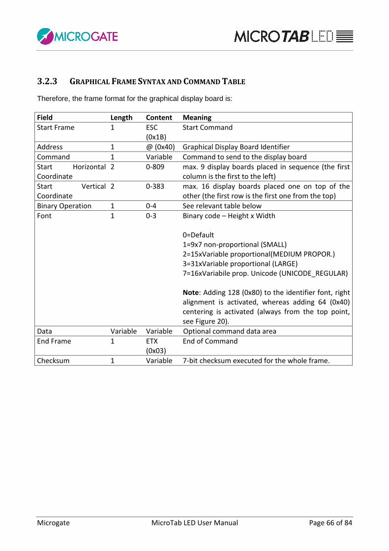
3.2.3 GRAPHICAL FRAME SYNTAX AND COMMAND TABLE
Therefore, the frame format for the graphical display board is:
Field Length Content Meaning
Start Frame 1 ESC (0x1B)
Start Command
Address 1 @ (0x40) Graphical Display Board Identifier
Command 1 Variable Command to send to the display board
Start Horizontal Coordinate
2 0-809 max. 9 display boards placed in sequence (the first column is the first to the left)
Start Vertical Coordinate
2 0-383 max. 16 display boards placed one on top of the other (the first row is the first one from the top)
Binary Operation 1 0-4 See relevant table below
Font 1 0-3 Binary code – Height x Width 0=Default 1=9x7 non-proportional (SMALL) 2=15xVariable proportional(MEDIUM PROPOR.) 3=31xVariable proportional (LARGE) 7=16xVariabile prop. Unicode (UNICODE_REGULAR) Note: Adding 128 (0x80) to the identifier font, right alignment is activated, whereas adding 64 (0x40) centering is activated (always from the top point, see Figure 20).
Data Variable Variable Optional command data area
End Frame 1 ETX (0x03)
End of Command
Checksum 1 Variable 7-bit checksum executed for the whole frame.
Microgate MicroTab LED User Manual Page 67 of 84
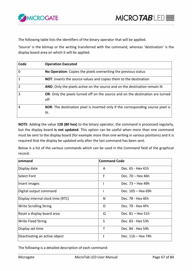
The following table lists the identifiers of the binary operator that will be applied.
'Source' is the bitmap or the writing transferred with the command, whereas ‘destination’ is the
display board area on which it will be applied.
Code Operation Executed
0 No Operation: Copies the pixels overwriting the previous status
1 NOT: Inverts the source values and copies them to the destination
2 AND: Only the pixels active on the source and on the destination remain lit
3 OR: Only the pixels turned off on the source and on the destination are turned
off
4 XOR: The destination pixel is inverted only if the corresponding source pixel is
lit.
NOTE: Adding the value 128 (80 hex) to the binary operator, the command is processed regularly,
but the display board is not updated. This option can be useful when more than one command
must be sent to the display board (for example more than one writing in various positions) and it is
required that the display be updated only after the last command has been sent.
Below is a list of the various commands which can be used in the Command field of the graphical
record:
ommand Command Code
Display date A Dec. 65 - Hex 41h
Select Font F Dec. 70 – Hex 46h
Insert images I Dec. 73 – Hex 49h
Digital output command i Dec. 105 – Hex 69h
Display internal clock time (RTC) N Dec. 78 - Hex 4Eh
Write Scrolling String O Dec. 79 - Hex 4Fh
Reset a display board area Q Dec. 81 – Hex 51h
Write Fixed String S Dec. 83 - Hex 53h
Display set time T Dec. 84 - Hex 54h
Deactivating an active object t Dec. 116 – Hex 74h
The following is a detailed description of each command:

Microgate MicroTab LED User Manual Page 68 of 84
Display Date – Active Object Command code ‘A’
Data area
Item Length (bytes) Notes
Mode 1 1=DD/MM/YY 2=DD MM YY
Select Font If you want to use the graphical display board in MicroTab-compatible mode, you must specify the display
font. This command sets the font for all display boards and prepares them to receive commands with an
identifier unequal to ‘@’. When turned on, the default font is 15x24 (TBD).
Command code ‘F’
Data area
Item Length (bytes) Notes
None (uses the font field of the graph header to set the font)
Insert Images This command is used to display Bitmap images on the graphical display board. Each data bit placed at ‘1’
corresponds to a lit pixel of the image. The image is scanned vertically, sending one column at a time,
aligned to the byte. No compression is provided
Command code ‘I’
Data area
Item Length (bytes) Notes
X Dimension 2 Horizontal image dimension, in pixels
Y Dimension 2 Vertical image dimension, in pixels
Image data ? Each pixel column is sent starting from the top. The Least Significant bit is the highest pixel. The last byte of the column is padded with zeroes, if the vertical image size is different from n*8.
Digital output command Command code ‘i’
Data area
Item Length (bytes) Notes
Input/Output control 1 Uses bits from 0 to 3 to select the mode of digital I/O from 0 to 3 (0 = output, 1 = input).
Digital output value 1 Uses bits from 0 to 4 to set the value on digital outputs from 0 to 4. (0 = 0V, 1 = 5V)

Microgate MicroTab LED User Manual Page 69 of 84
Internal Clock Display (RTC) – Active Object Command code ‘N’
Data area
Item Length (bytes) Notes
Display format 1 1 (binary) = HH:MM:SS 2 (binary) = MM:SS 3 (binary) = HH:MM (24h) 4 (binary) = HH:MM (12h)
Delay 4 long integer (31 bit + symbol) with advance or delay of the displayed time with respect to the internal clock (Real Time Clock), expressed in thousandths.
Write Scrolling String– Active Object Command code ‘O’
Data area
Item Length (bytes) Notes
Writing width 2 Writing width in pixels (binary word)
Display delay 2 Scrolling delay (Frame to Frame) in hundredths (white word)
Display width 1 Display width in pixels (binary)
Writing ? From 1 to 255 characters + 'null terminator'
Write Fixed String Command code ‘G’
Data area
Item Length (bytes) Notes
String <=81 Characters to display (with null terminator)

Microgate MicroTab LED User Manual Page 70 of 84
Reset a display board area Command code ‘Q’
Data area
Item Length (bytes) Notes
X Dimension 2 Horizontal Dimension of the area to reset
Y Dimension 2 Vertical Dimension of the area to reset
Deactivating an active object Command code ‘t’
Data area
Item Length (bytes) Notes
None The object identified by the position X, Y transmitted by the graphical frame

Microgate MicroTab LED User Manual Page 71 of 84
3.2.3.1 EXAMPLE
Write 'Microgate' at position X=90, Y=48 with MEDIUM Font String to send:
Field Byte Content (hex)
Meaning
Start Frame 0 0x1B Start Command
Address 1 0x40 Graphical Display Board Identifier
Command 2 0x53 Fixed String Command
Start Horizontal Coordinate (First byte)
3 0x5A X= 90 -> in hex 0x5A
Start Horizontal Coordinate (Second byte)
4 0x00
Start Vertical Coordinate (First byte)
5 0x30 Y = 48 -> in hex 0x30
Start Vertical Coordinate (Second byte)
6 0x00
Binary Operation 7 0x00 No Operation
Font 8 0x02 MEDIUM Font
Data 9 0x4D Character M
Data 10 0x49 Character I
Data 11 0x43 Character C
Data 12 0x52 Character R
Data 13 0x4F Character O
Data 14 0x47 Character G
Data 15 0x41 Character A
Data 16 0x54 Character T
Data 17 0x45 Character E
End Frame 18 0x03 End of Command
Checksum 19 0x58 7-bit checksum executed for the whole frame: 0x1B+0x40+0x53+0x5A+0x30+0x02+0x4D+0x49+0x43+0x52+0x4F+0x47+0x41+0x54+0x45+0x03 = 0x3D8 0x3D8 AND 0x7F = 0x58

Microgate MicroTab LED User Manual Page 72 of 84
3.3 UNICODE FRAME
Unlike the previous pixel-based version, MicroTab LED can manage the Unicode protocol for
displaying non-ASCII 2-byte characters, as for example Chinese, Japanese, Cyrillic, etc.
3.3.1 GRAPHICAL UNICODE FRAME SYNTAX AND COMMAND TABLE
The transmission protocol is completely identical to the Graphical Frame (GRAPH Protocol, see
par. 3.2), with the exception of the transmission of the Data area, where the single characters
must be sent specifying that they are 2-byte characters and ending the string with an ETX Unicode
character (0x2403). Then the ETX (0x03) ASCII character must be sent anyway, just like for other
protocols. It is important to remember to use one of the Unicode fonts (7 or 8).
Write Fixed String Command code ‘H’
Data area
Item Length (bytes) Notes
String <=81 Unicode characters to display
Write Scrolling String– Active Object Command code ‘h’
Data area
Item Length (bytes) Notes
Writing width 2 Writing width in pixels (binary word)
Display delay 2 Scrolling delay (Frame to Frame) in hundredths (white word)
Display width 1 Display width in pixels (binary)
Writing ? Unicode scrolling string

Microgate MicroTab LED User Manual Page 73 of 84
3.3.1.1 EXAMPLE
Write “您好” at position X=90, Y=48 with UNICODE_MEDIUM Font String to send:
Field Byte Content (hex)
Meaning
Start Frame 0 0x1B Start Command
Address 1 0x40 Graphical Display Board Identifier
Command 2 0x53 Fixed String Command
Start Horizontal Coordinate (First byte)
3 0x5A X= 90 -> in hex 0x5A
Start Horizontal Coordinate (Second byte)
4 0x00
Start Vertical Coordinate (First byte)
5 0x30 Y = 48 -> in hex 0x30
Start Vertical Coordinate (Second byte)
6 0x00
Binary Operation 7 0x00 No Operation
Font 8 0x07 Font UNICODE MEDIUM
Data 9 0x60 First byte of 您 character
Data 10 0xA8 Second byte of 您 character
Data 11 0x59 First byte of 好 character
Data 12 0x7D Second byte of 好 character
End of Unicode Data 13 0x24 First byte of UETX character
End of Unicode Data 14 0x03 Second byte of UETX character
End Frame 15 0x03 End of Command
Checksum 16 0x3C 7-bit checksum executed for the whole frame

Microgate MicroTab LED User Manual Page 74 of 84
4 MICROGATE.DISPBOARD.MANAGER API
The Microgate.DispBoard.Manager library has been developed for .NET Framework 3.5 and allows
you to manage Microgate pixel and LED display boards.
The main class is called DisplayBoardManager and once instanced it allows you to send all
available commands to the display board (via serial port, or, for LED display boards, via
Ethernet/WiFi), acting as wrapper for the already existing serial protocol. Thanks to this it is not
necessary to learn the exact syntax of all commands and to pay attention to the transmission
details like checksum, protocol identifiers, etc.
It is possible to use both protocols (ALPHA and GRAPH). In the ALPHA protocol, the row is
generally set via the RowAddress property and the column via a parameter of methods
providing for it; e.g. WriteString(int column,string message)
The GRAPH protocol, on the contrary, allows you to specify single dot positioning using X and Y
coordinates (string, date, clock, scrolling string, image, etc.) and to vary the font and alignment
using two properties (Font and Alignment). Alignment means the variation of the point origin
on the top of the primitive, which will be shifted to the left, center, or right, respectively.
Therefore, if you want to align a string to the right, remember to shift X to the desired spot
(keeping it at 0, the writing would move 'out' of the display board).
Figure 20 - Example of left, center, and right alignment

Microgate MicroTab LED User Manual Page 75 of 84
4.1 CONSTRUCTOR
The class must be instanced giving the constructor 3 main parameters (which set the relative
properties):
- Technology (LED | PIXEL)
- Model (MicroTab | MicroTab)
- CommunicationProtocol ( Serial | Ethernet | Wifi | Fileout)
For all three mnemonic enums are available
Depending on the chosen communication protocol, the relevant properties for communication
must be set immediately afterwards:
SERIAL ETHERNET WIFI FILEOUT
PortName (e.g. 'COM1') BaudRate (e.g. 9600)
EthIpAddress ('192.168.0.123') EthPortNumber (21967)
WifiIpAddress ('192.168.0.124') WifiPortNumber (21968)
FileNameOut
('c:\sample.txt')
4.2 CONNECTION
To establish the connection with the display board, you can use the OpenConnection()
method and, if necessary, check that the connection has been established with the property
Connected. Similarly, CloseConnection() closes the connection. The class implements the
interface IDisposable, therefore, to free and close all resources use the method Dispose()
or the statement using (C#).
In any case, it is possible to avoid the explicit opening of the serial port or the TCP socket, carried
out upon first use of a primitive or command.
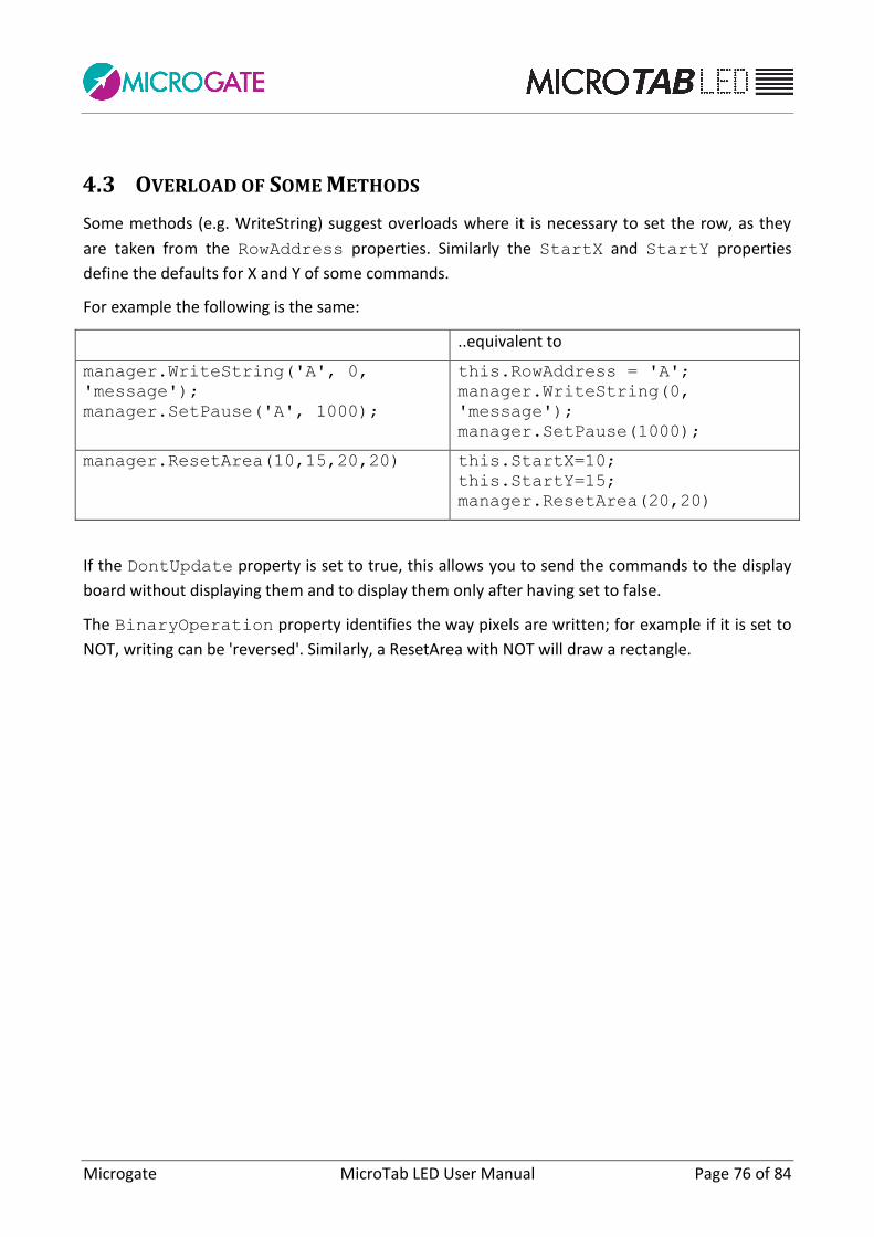
Microgate MicroTab LED User Manual Page 76 of 84
4.3 OVERLOAD OF SOME METHODS
Some methods (e.g. WriteString) suggest overloads where it is necessary to set the row, as they
are taken from the RowAddress properties. Similarly the StartX and StartY properties
define the defaults for X and Y of some commands.
For example the following is the same:
..equivalent to
manager.WriteString('A', 0,
'message'); manager.SetPause('A', 1000);
this.RowAddress = 'A'; manager.WriteString(0,
'message'); manager.SetPause(1000);
manager.ResetArea(10,15,20,20) this.StartX=10; this.StartY=15; manager.ResetArea(20,20)
If the DontUpdate property is set to true, this allows you to send the commands to the display
board without displaying them and to display them only after having set to false.
The BinaryOperation property identifies the way pixels are written; for example if it is set to
NOT, writing can be 'reversed'. Similarly, a ResetArea with NOT will draw a rectangle.

Microgate MicroTab LED User Manual Page 77 of 84
4.4 MAIN METHODS
The main methods for writing objects on the display board are: - ShowDate
- ShowClock1
- ShowClock2
- WriteString
- WriteRunningString
- DrawImage
- DrawPixel
Before using the calendar and the two internal clocks, they must be set to the relative methods. - SetDate
- SetClock1
- SetClock2
Some objects are called 'active', because once turned on they are updated automatically and to stop them they can be stopped with the following (as well as with the reset commands):
- DisableDate
- DisableClock1
- DisableClock2
- StopRunningString
- DisableActiveObject
Then there is a whole series of commands for setting the parameters of the display board, similarly to what can be done via its internal setup. For example:
- SetBrightness
- SetWifiNetworkKey
- SetBaudRate
- etc. Finally, several methods manage the 'internal user programs', i.e. the possibility to create small programs to be executed by the display board:
- UserProgramStart
- UserProgramEnd
- EntryPointLabel
- LoopGoto
- The (modular) multiple-row/column LED display board configuration can be performed on the display board, as well as with commands:
- AutoConfig
- equivalent to SetAutoConfigInit + SetAutoConfigParams - and checked with IdentifyMe

Microgate MicroTab LED User Manual Page 78 of 84
4.5 EXAMPLE
//Instance a class to manage a MicroTab LED via Ethernet DisplayBoardManager mgr = new DisplayBoardManager( Technology.LED, Model.MICROTAB, CommunicationProtocol.Ethernet); mgr.EthIPAddress = "192.168.0.123"; mgr.EthPortNumber = 21967; //Or via Serial port /* DisplayBoardManager mgr2 = new DisplayBoardManager (Technology.LED, Model.MICROTAB, CommunicationProtocol.Serial); mgr2.PortName = "COM1"; mgr2.BaudRate = 9600; */ // Opening Connection... (not necessary, is opened anyway with the first command) mgr.OpenConnection(); //check if connected if (!mgr.Connected) { //... } // Command examples // Reset mgr.StrongReset(); //Set brightness mgr.SetBrightnessType(BrightnessType.MANUAL); mgr.SetBrightness(50); // Writing String with graphical protocol x,y mgr.Font = GraphFont.HUGE; mgr.WriteString(0, 0, "BIG"); mgr.Font = GraphFont.SMALL; mgr.Alignment = Alignment.RIGHT; mgr.WriteString(128, 22, "small"); //Writing String with alpha protocol row,column mgr.WriteString("A", 6, "medium"); // Set Real Time Clock to 00:00 and display in x,y mgr.SetClock1(0,0,0,0); mgr.Alignment = Alignment.LEFT; mgr.ShowClock1(54, 22,TimeFormat.MM_SS,0); //Cleaning... mgr.CloseConnection(); mgr.Dispose();

Microgate MicroTab LED User Manual Page 79 of 84
4.6 METHODS
Name Description
AutoConfig Autoconfig of the display boards
CloseConnection Closes the connection.
DisableActiveObject Disables the active object.
DisableClock1 Stops the real time clock 1.
DisableClock2 Disables the clock2.
DisableDate Stops the date.
Dispose Performs application-defined tasks associated with
freeing, releasing, or resetting unmanaged resources.
DrawArea Resets the area with NOT mode; resets the old
binaryOperation property at the end.
DrawImage Overloaded.
DrawPixel Draws the pixel.
EnablePixEmulation Enables the emulation of old MicroTab PIXEL display
boards.
EnableWIFI Enables the WIFI card.
EntryPointLabel Overloaded.
Equals Determines whether the specified Object is equal to
the current Object.
(Inherited from Object.)
ExecuteUserProgram Overloaded.
Finalize Allows an Object to attempt to free resources and
perform other cleanup operations before the Object is
reclaimed by garbage collection.
(Inherited from Object.)
GetDimension Overloaded.
GetHashCode Serves as a hash function for a particular type.
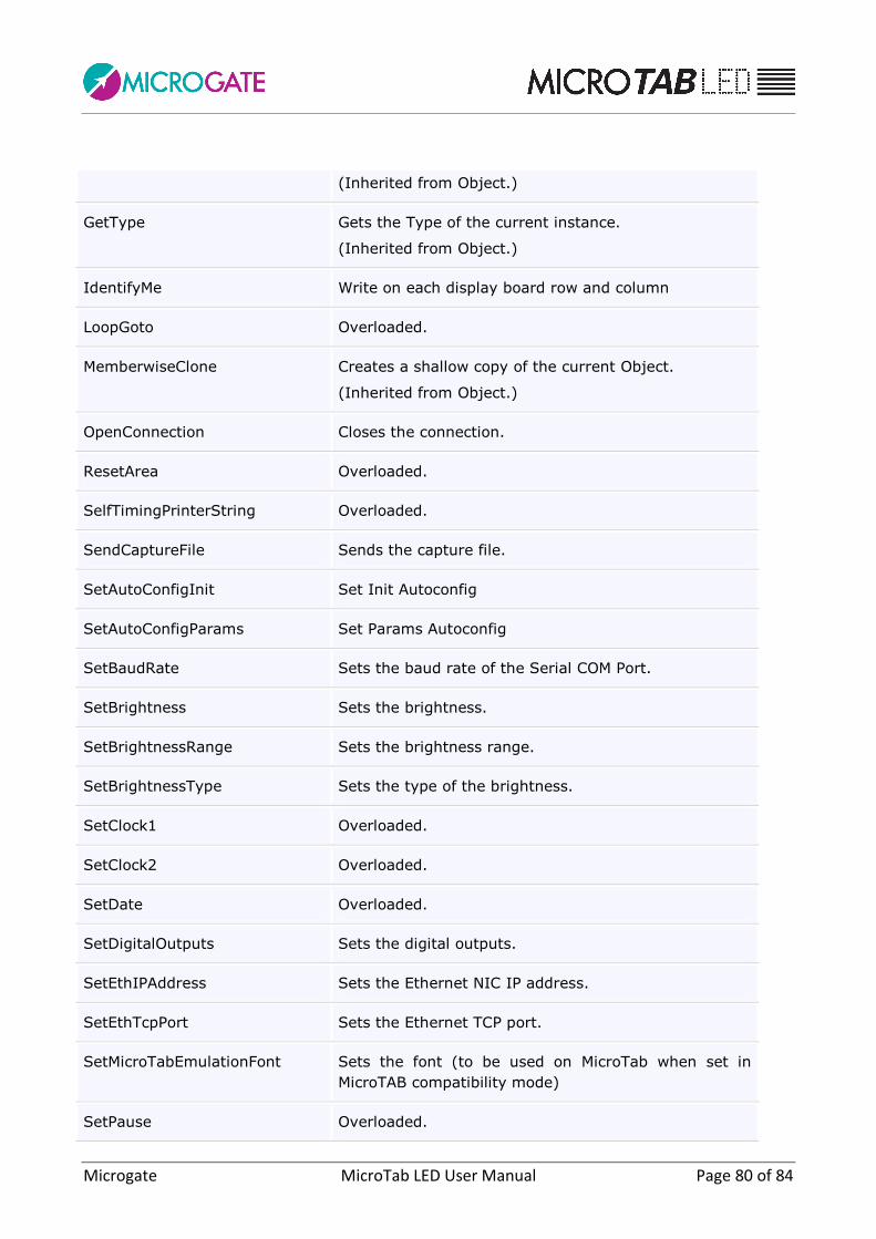
Microgate MicroTab LED User Manual Page 80 of 84
(Inherited from Object.)
GetType Gets the Type of the current instance.
(Inherited from Object.)
IdentifyMe Write on each display board row and column
LoopGoto Overloaded.
MemberwiseClone Creates a shallow copy of the current Object.
(Inherited from Object.)
OpenConnection Closes the connection.
ResetArea Overloaded.
SelfTimingPrinterString Overloaded.
SendCaptureFile Sends the capture file.
SetAutoConfigInit Set Init Autoconfig
SetAutoConfigParams Set Params Autoconfig
SetBaudRate Sets the baud rate of the Serial COM Port.
SetBrightness Sets the brightness.
SetBrightnessRange Sets the brightness range.
SetBrightnessType Sets the type of the brightness.
SetClock1 Overloaded.
SetClock2 Overloaded.
SetDate Overloaded.
SetDigitalOutputs Sets the digital outputs.
SetEthIPAddress Sets the Ethernet NIC IP address.
SetEthTcpPort Sets the Ethernet TCP port.
SetMicroTabEmulationFont Sets the font (to be used on MicroTab when set in
MicroTAB compatibility mode)
SetPause Overloaded.

Microgate MicroTab LED User Manual Page 81 of 84
SetRadioChannel Sets the radio channel for Linkgate.
SetupInternalProgramParameter Overloaded.
SetWifiIPAddress Sets the WIFI NIC IP address.
SetWifiNetworkKey Sets the Key (password) of the WPA-PSK WiFi network
(blank if none).
SetWifiNetworkSSID Sets the SSID of the WIFI network where the display
board is attached.
SetWifiTcpPort Sets the WIFI TCP port.
ShowClock1 Overloaded.
ShowClock2 Overloaded.
ShowDate Overloaded.
StopRunningString Overloaded.
StrongReset Overloaded.
ToString Returns a String that represents the current Object.
(Inherited from Object.)
UserProgramEnd Overloaded.
UserProgramStart Overloaded.
WeakReset Overloaded.
WriteRunningString Overloaded.
WriteString Overloaded.
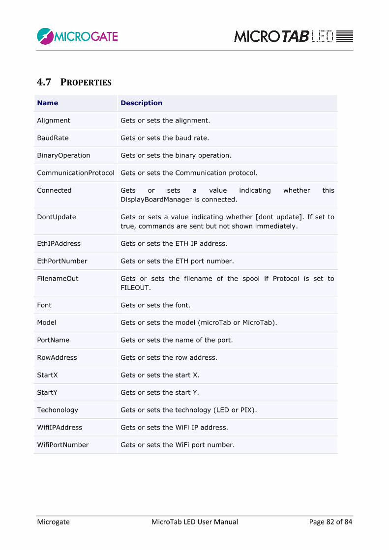
Microgate MicroTab LED User Manual Page 82 of 84
4.7 PROPERTIES
Name Description
Alignment Gets or sets the alignment.
BaudRate Gets or sets the baud rate.
BinaryOperation Gets or sets the binary operation.
CommunicationProtocol Gets or sets the Communication protocol.
Connected Gets or sets a value indicating whether this
DisplayBoardManager is connected.
DontUpdate Gets or sets a value indicating whether [dont update]. If set to
true, commands are sent but not shown immediately.
EthIPAddress Gets or sets the ETH IP address.
EthPortNumber Gets or sets the ETH port number.
FilenameOut Gets or sets the filename of the spool if Protocol is set to
FILEOUT.
Font Gets or sets the font.
Model Gets or sets the model (microTab or MicroTab).
PortName Gets or sets the name of the port.
RowAddress Gets or sets the row address.
StartX Gets or sets the start X.
StartY Gets or sets the start Y.
Techonology Gets or sets the technology (LED or PIX).
WifiIPAddress Gets or sets the WiFi IP address.
WifiPortNumber Gets or sets the WiFi port number.

Microgate MicroTab LED User Manual Page 83 of 84
Copyright
Copyright © 2011 by Microgate S.r.l.
All rights reserved
No part of this document or of any of the individual manuals may be copied or reproduced
without prior written authorization by Microgate s.r.l.
All the trademarks or names of products mentioned in this document or in the individual manuals
are or may be registered trademarks belonging to the individual firms.
Microgate, REI2, RaceTime2, and MiSpeaker are registered trademarks belonging to Microgate
s.r.l. Windows is a registered mark of Microsoft Co.
Microgate s.r.l. reserves the right to modify the products described in this document and/or in the
relative manuals without notice.
Microgate S.r.l.
Via Stradivari, 4
I-39100 Bolzano
ITALY
Tel. +39 0471 501532 - Fax +39 0471 501524
http://www.microgate.it

Microgate MicroTab LED User Manual Page 84 of 84


![User Guide...User. {{]}]} {}]}](https://img.pdfslide.net/doc/110x75/60918ca14327954d24291644/-user-guide-user-.jpg)