Embed Size (px)
Citation preview
Structural design aspects of bulk carriers
E. Lehmann, M. Bockenhauer, W. Fricke, H.-J. HansenGermanischer Lloyd
Vorsetzen 32, D-20459 Hamburg, Germany
Abstract
Large and efficient bulk carriers, designed and built mainly in the 1960's and 1970%, are nowreaching the end of their service life. The past few years have revealed several structuralproblems, which strongly affected the ships' safety. Although corrosion and bad maintenancewas found to contribute mostly to the problems, the strength behaviour and design criteriahave, nevertheless, to be reviewed taking into account the service experience observed. Afterdescribing different designs of bulk carriers and the governing structural design principles, thecriteria and models for the strength assessment based on first engineering principles aresummarised. Emphasis is placed on local strength analyses in order to cover fatigue aspects.Important will become also the strength analysis in flooded condition, considering extremeloads such as the pressure on bulkheads due to cargo and ingressed water. But ruledevelopments related to such aspects are still under discussion. Finally, corrosion and wastageaspects are discussed which need to be considered more thoroughly as service experience hasshown.
1 Introduction
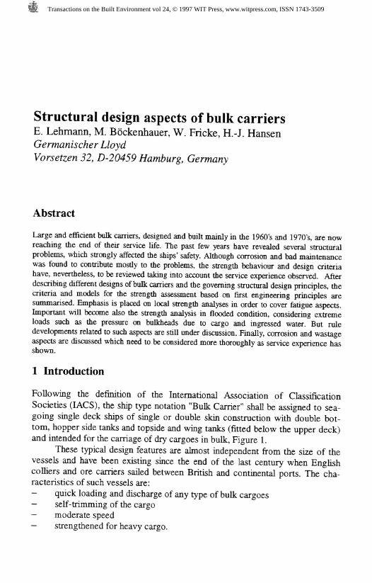
Following the definition of the International Association of ClassificationSocieties (IACS), the ship type notation "Bulk Carrier" shall be assigned to sea-going single deck ships of single or double skin construction with double bot-tom, hopper side tanks and topside and wing tanks (fitted below the upper deck)and intended for the carriage of dry cargoes in bulk, Figure 1.
These typical design features are almost independent from the size of thevessels and have been existing since the end of the last century when Englishcolliers and ore carriers sailed between British and continental ports. The cha-racteristics of such vessels are:- quick loading and discharge of any type of bulk cargoes- self-trimming of the cargo- moderate speed- strengthened for heavy cargo.
Transactions on the Built Environment vol 24, © 1997 WIT Press, www.witpress.com, ISSN 1743-3509
26 Marine Technology II
Wing Tank
Fig. 1: Midship Section of a Bulk Carrier
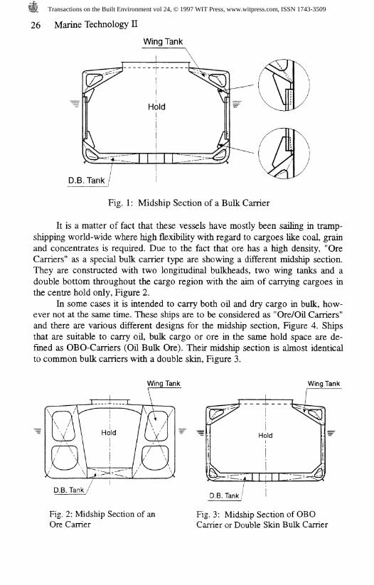
It is a matter of fact that these vessels have mostly been sailing in tramp-shipping world-wide where high flexibility with regard to cargoes like coal, grainand concentrates is required. Due to the fact that ore has a high density, "OreCarriers" as a special bulk carrier type are showing a different midship section.They are constructed with two longitudinal bulkheads, two wing tanks and adouble bottom throughout the cargo region with the aim of carrying cargoes inthe centre hold only, Figure 2.
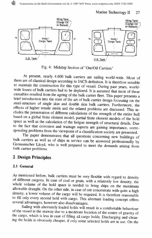
In some cases it is intended to carry both oil and dry cargo in bulk, how-ever not at the same time. These ships are to be considered as "Ore/Oil Carriers"and there are various different designs for the midship section, Figure 4. Shipsthat are suitable to carry oil, bulk cargo or ore in the same hold space are de-fined as OBO-Carriers (Oil Bulk Ore). Their midship section is almost identicalto common bulk carriers with a double skin, Figure 3.
Wing Tank
D.B. Tank /
Fig. 2: Midship Section of anOre Carrier
Fig. 3: Midship Section of OBOCarrier or Double Skin Bulk Carrier
Transactions on the Built Environment vol 24, © 1997 WIT Press, www.witpress.com, ISSN 1743-3509
Wing Tank(Cargo Oilor Ballast)
Marine Technology II 27
Wing Tank(Cargo Oil Ior Ballast)/
Fig. 4: Midship Section of "Ore/Oil Carriers"
At present, nearly 4.600 bulk carriers are sailing world-wide. Most ofthem are of classical design according to lACS-definition. It is therefore sensibleto maintain the construction for this type of vessel. During past years world-wide losses of bulk carriers had to be deplored. It is assumed that most of thesecasualties resulted from the ageing of the bulk carrier fleet. This paper presents abrief introduction into the state of the art of bulk carrier design focussing on thesteel-structure of single skin and double skin bulk carriers. Furthermore, theeffects of higher tensile steels and the related problems are discussed. TMs in-cludes the presentation of different calculations of the strength of the entire hullbased on a global finite element model, partial finite element models of the holdspace as well as the calculation of the fatigue strength of structural details. Dueto the fact that corrosion and wastage aspects are gaining importance, corre-sponding problems from the viewpoint of a classification society are presented.
The paper demonstrates that all questions concerning new buildings ofbulk carriers as well as of ships in service can be answered professionally byGermanischer Lloyd, who is well prepared to meet the demands arising frombulk carrier problems.
2 Design Principles
2.1 General
As mentioned before, bulk carriers must be very flexible with regard to densityof different cargoes. In case of coal or grain, with a relatively low density thewhole volume of the hold space is needed to bring ships on the maximumallowable draught. On the other side, in case of ore concentrate with quite a highdensity, a lower volume of the cargo will be required. It is therefore reasonableto fill only every second hold with cargo. This alternate loading concept offersseveral advantages, however also disadvantages.
Sailing with alternately loaded holds will result in a comfortable behaviourof the vessel in the seaway due to a moderate location of the centre of gravity ofthe cargo, which is less in case of filling all cargo holds. Discharging and clean-ing the holds is obviously cheaper, if only some selected holds are in use. On the
Transactions on the Built Environment vol 24, © 1997 WIT Press, www.witpress.com, ISSN 1743-3509
28 Marine Technology II
other hand, vessels intended for alternate loading have to be reinforced due toadditional shear forces, in particular in the shell area in the vicinity of the trans-verse bulkheads between loaded and unloaded holds. This becomes more seriousin case of flooded holds - which is under discussion within I ACS.
2.2 Single Skin or Double Skin
The most important question today is how to design the vessel's shell - single ordouble skinned - and what type of structural design of the transverse bulkheadsis the most reasonable one.
As mentioned before, the end connections of transverse frames of singleskin type design are very vulnerable. Therefore the double skin design is prefer-able. It must be kept in mind that double skins are reducing the cargo hold vol-ume because the distance between outer and inner skin must be wide enough toallow inspection (approx. 1000 mm). On the other hand, in case of double skin,the cargo holds are kept free from any arrangements like brackets or other simi-lar structural elements.
A further advantage of the double skin design can be seen in better pro-tection of the steel structure within the double skin space against tear and wearcaused by loading and discharging procedures. However, the void space is rec-ommended to be coated in order to prevent corrosion. From the structural point-of-view, double skin structures between upper and lower wingtanks yield to amore homogeneous distribution of the structural stiffness with regard to thetransverse strength of the entire hull.
2.3 Transverse Bulkheads
Structural design of transverse bulkheads of bulk carriers is somehow differentfrom the one applying to dry cargo vessels in general. This is due to conditionthat they have to resist against heavy bulk cargo pressure, which can be muchhigher than the water pressure usually taken into account. Another designprinciple to be considered is that no cargo residues should remain on the bulk-head structures after cargo discharge.
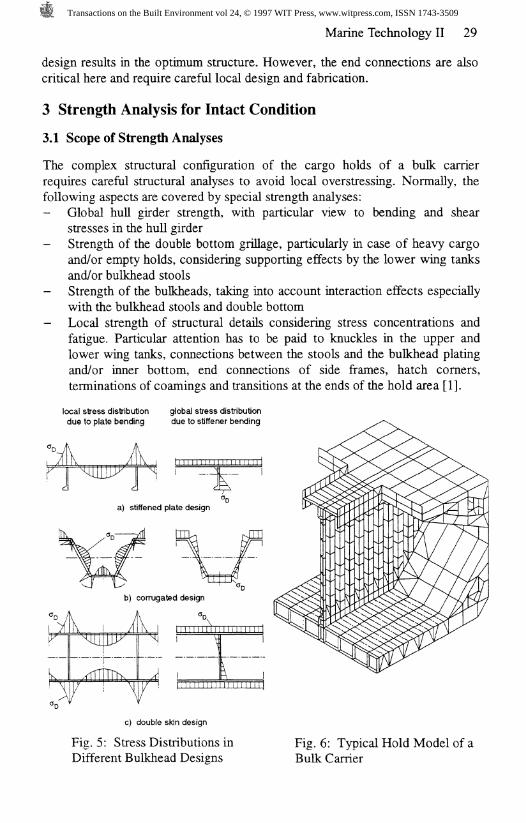
Figure 5 shows the different types of structural designs of bulkheads. Thestiffened plane bulkhead design which is normally used in dry cargo vessels, isrestricted to very small bulk carriers only. In case of bigger vessels the stiffenersbecome very heavy, even if supported by horizontal stringers, apart from the factthat these are disturbing the selftrimming discharge procedure because bulkcargo residues are unavoidable.
As can be seen from Figure 5a (stiffened plate design), the local platebending stresses (%) do not coincide with the maximum global stresses resultingfrom stiffener bending. However, in case of corrugated bulkheads the local platebending stresses (%) coincide with the maximum global bending stresses, just asin case of the double skin design.
Weight optimisation calculations have shown that the corrugated bulkhead
Transactions on the Built Environment vol 24, © 1997 WIT Press, www.witpress.com, ISSN 1743-3509
Marine Technology II 29
design results in the optimum structure. However, the end connections are alsocritical here and require careful local design and fabrication.
3 Strength Analysis for Intact Condition
3.1 Scope of Strength Analyses
The complex structural configuration of the cargo holds of a bulk carrierrequires careful structural analyses to avoid local overstressing. Normally, thefollowing aspects are covered by special strength analyses:- Global hull girder strength, with particular view to bending and shear
stresses in the hull girder- Strength of the double bottom grillage, particularly in case of heavy cargo
and/or empty holds, considering supporting effects by the lower wing tanksand/or bulkhead stools
- Strength of the bulkheads, taking into account interaction effects especiallywith the bulkhead stools and double bottom
- Local strength of structural details considering stress concentrations andfatigue. Particular attention has to be paid to knuckles in the upper andlower wing tanks, connections between the stools and the bulkhead platingand/or inner bottom, end connections of side frames, hatch corners,terminations of coamings and transitions at the ends of the hold area [1].
local stress distributiondue to plate bending
global stress distributiondue to stiffener bending
a) stiffened plate design
^̂ WLb) corrugated design
c) double skin design
Fig. 5: Stress Distributions inDifferent Bulkhead Designs
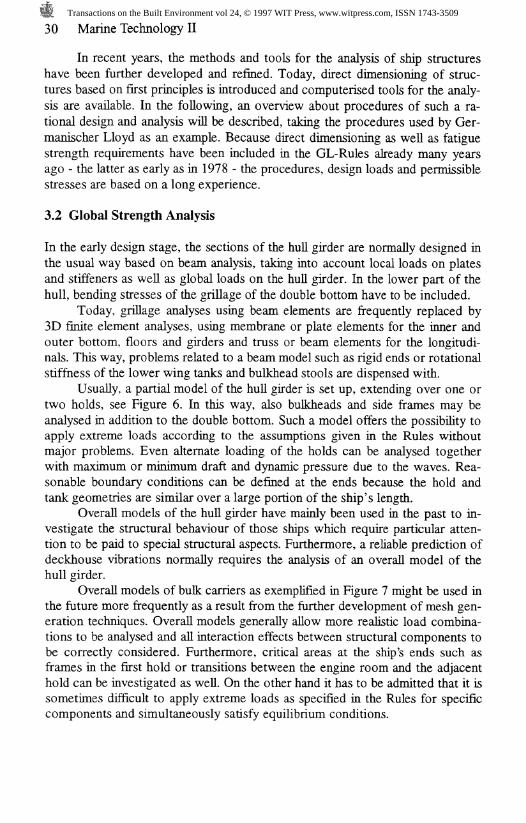
Fig. 6: Typical Hold Model of aBulk Carrier
Transactions on the Built Environment vol 24, © 1997 WIT Press, www.witpress.com, ISSN 1743-3509
30 Marine Technology II
In recent years, the methods and tools for the analysis of ship structureshave been further developed and refined. Today, direct dimensioning of struc-tures based on first principles is introduced and computerised tools for the analy-sis are available. In the following, an overview about procedures of such a ra-tional design and analysis will be described, taking the procedures used by Ger-manischer Lloyd as an example. Because direct dimensioning as well as fatiguestrength requirements have been included in the GL-Rules already many yearsago - the latter as early as in 1978 - the procedures, design loads and permissiblestresses are based on a long experience.
3.2 Global Strength Analysis
In the early design stage, the sections of the hull girder are normally designed inthe usual way based on beam analysis, taking into account local loads on platesand stiffeners as well as global loads on the hull girder. In the lower part of thehull, bending stresses of the grillage of the double bottom have to be included.
Today, grillage analyses using beam elements are frequently replaced by3D finite element analyses, using membrane or plate elements for the inner andouter bottom, floors and girders and truss or beam elements for the longitudi-nals. This way, problems related to a beam model such as rigid ends or rotationalstiffness of the lower wing tanks and bulkhead stools are dispensed with.
Usually, a partial model of the hull girder is set up, extending over one ortwo holds, see Figure 6. In this way, also bulkheads and side frames may beanalysed in addition to the double bottom. Such a model offers the possibility toapply extreme loads according to the assumptions given in the Rules withoutmajor problems. Even alternate loading of the holds can be analysed togetherwith maximum or minimum draft and dynamic pressure due to the waves. Rea-sonable boundary conditions can be defined at the ends because the hold andtank geometries are similar over a large portion of the ship's length.
Overall models of the hull girder have mainly been used in the past to in-vestigate the structural behaviour of those ships which require particular atten-tion to be paid to special structural aspects. Furthermore, a reliable prediction ofdeckhouse vibrations normally requires the analysis of an overall model of thehull girder.
Overall models of bulk carriers as exemplified in Figure 7 might be used inthe future more frequently as a result from the further development of mesh gen-eration techniques. Overall models generally allow more realistic load combina-tions to be analysed and all interaction effects between structural components tobe correctly considered. Furthermore, critical areas at the ship's ends such asframes in the first hold or transitions between the engine room and the adjacenthold can be investigated as well. On the other hand it has to be admitted that it issometimes difficult to apply extreme loads as specified in the Rules for specificcomponents and simultaneously satisfy equilibrium conditions.
Transactions on the Built Environment vol 24, © 1997 WIT Press, www.witpress.com, ISSN 1743-3509
Marine Technology II 31
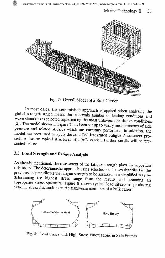
Fig. 7: Overall Model of a Bulk Carrier
In most cases, the deterministic approach is applied when analysing theglobal strength which means that a certain number of loading conditions andwave situations is selected representing the most unfavourable design conditions[2]. The model shown in Figure 7 has been set up to verify measurements of sidepressure and related stresses which are currently performed. In addition themodel has been used to apply the so-called Integrated Fatigue Assessment'pro-cedure also on typical structures of a bulk carrier. Further details will be pre-sented below. ^
3.3 Local Strength and Fatigue Analysis
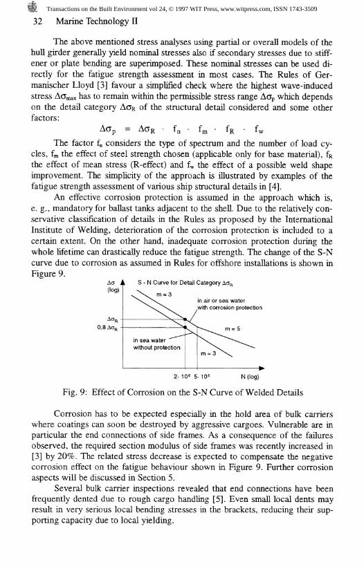
As already mentioned, the assessment of the fatigue strength plays an importantrole today. The deterministic approach using selected load cases described in theprevious chapter allows the fatigue strength to be assessed in a simplified way bydetermining the highest stress range from the results and assuming anappropriate stress spectrum. Figure 8 shows typical load situations producingextreme stress fluctuations in the transverse members of a bulk carier
Fig. 8: Load Cases with High Stress Fluctuations in Side Frames
Transactions on the Built Environment vol 24, © 1997 WIT Press, www.witpress.com, ISSN 1743-3509
32 Marine Technology II
The above mentioned stress analyses using partial or overall models of thehull girder generally yield nominal stresses also if secondary stresses due to stiff-ener or plate bending are superimposed. These nominal stresses can be used di-rectly for the fatigue strength assessment in most cases. The Rules of Ger-manischer Lloyd [3] favour a simplified check where the highest wave-inducedstress ACmax has to remain within the permissible stress range ACp which dependson the detail category A<JR of the structural detail considered and some otherfactors:
A<3p = A<jR • fn ' fm ' fR ' fw
The factor f^ considers the type of spectrum and the number of load cy-cles, fm the effect of steel strength chosen (applicable only for base material), &the effect of mean stress (R-effect) and f* the effect of a possible weld shapeimprovement. The simplicity of the approach is illustrated by examples of thefatigue strength assessment of various ship structural details in [4].
An effective corrosion protection is assumed in the approach which is,e. g., mandatory for ballast tanks adjacent to the shell. Due to the relatively con-servative classification of details in the Rules as proposed by the InternationalInstitute of Welding, deterioration of the corrosion protection is included to acertain extent. On the other hand, inadequate corrosion protection during thewhole lifetime can drastically reduce the fatigue strength. The change of the S-Ncurve due to corrosion as assumed in Rules for offshore installations is shown inFigure 9.
in air or sea water,with corrosion protection
0,8 Ac,
2- 10* 5- 1QG N (log)
Fig. 9: Effect of Corrosion on the S-N Curve of Welded Details
Corrosion has to be expected especially in the hold area of bulk carrierswhere coatings can soon be destroyed by aggressive cargoes. Vulnerable are inparticular the end connections of side frames. As a consequence of the failuresobserved, the required section modulus of side frames was recently increased in[3] by 20%. The related stress decrease is expected to compensate the negativecorrosion effect on the fatigue behaviour shown in Figure 9. Further corrosionaspects will be discussed in Section 5.
Several bulk carrier inspections revealed that end connections have beenfrequently dented due to rough cargo handling [5]. Even small local dents mayresult in very serious local bending stresses in the brackets, reducing their sup-porting capacity due to local yielding.
Transactions on the Built Environment vol 24, © 1997 WIT Press, www.witpress.com, ISSN 1743-3509
Marine Technology II 33
I I I I I I I I n 1 1 1 1 1 1 1 1 1 1 m l i i i i i i t t + 4
Frame connected to upper web|
^ 1.0-o
<DD)CC
Frame not connected to upper web
I I I
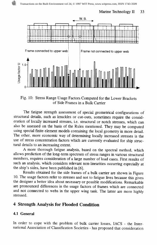
Fig. 10: Stress Range Usage Factors Computed for the Lower Bracketsof Side Frames in a Bulk Carrier
The fatigue strength assessment of special geometrical configurations ofstructural details, such as knuckles or cut-outs, sometimes require the consid-eration of locally increased stresses, i.e. structural or notch stresses, which canalso be assessed on the basis of the Rules mentioned. They may be computedusing special finite element models containing the local geometry in more detail.The other, more economic way of determining locally increased stresses is theuse of stress concentration factors which are currently evaluated for ship struc-tural details to an increasing extent.
A more thorough fatigue analysis, based on the spectral method, whichallows prediction of the long-term spectrum of stress ranges in various structuralmembers, requires consideration of a large number of load cases. First results ofsuch an analysis, which considers relevant non-linearities occurring especially atthe ship's sides, have been published in [6].
Results obtained for the side frames of a bulk carrier are shown in Figure10. The usage factors refer to stresses and not to fatigue lives because this givesthe designer a better idea about necessary or possible modifications. Remarkableare pronounced differences in the usage factors of frames which are connectedand not connected to webs in the upper wing tank. The latter are more highlystressed.
4 Strength Analysis for Flooded Condition
4.1 General
In order to cope with the problem of bulk carrier losses, IACS - the Inter-national Association of Classification Societies - has proposed that consideration
Transactions on the Built Environment vol 24, © 1997 WIT Press, www.witpress.com, ISSN 1743-3509
34 Marine Technology II
should be given to the strength of bulk carriers in flooded condition. Relevantunified requirements (UR) have been elaborated and are still under development,i. e. UR-S17 for the longitudinal strength in flooded condition, UR-S18 forvertically corrugated transverse watertight bulkheads and UR-S20 for the doublebottom. The intention is to apply these requirements to all new single side skinbulk carriers of 150 m in length and above, which are contracted forconstruction after 1* July, 1998. In addition similar standards with respect tobulkheads and double bottom have been elaborated for existing ships of the sameidentity.
Contrary to the damage stability calculation according to IMO-Regula-tions, where an exchange between cargo and ingressed water is assumed,flooded condition in this context means that each cargo hold is assumed to beseparately flooded by an opening in the side shell. This opening is not defined insize and location but allows the ingress of water until the equilibrium waterline isreached. Thus, in this scenario the strength check has to be done in addition tothe strength in the intact still water loading conditions defined in the loadingmanual, but it has to be well understood as a "case of emergency".
4.2 Longitudinal Strength
Depending on the number of cargo holds as many loading cases in stillwatercondition have to be calculated with regard to their bending moment and shearforce distribution along the ship's length, each single cargo hold assumed to beflooded up to the equilibrium waterline.
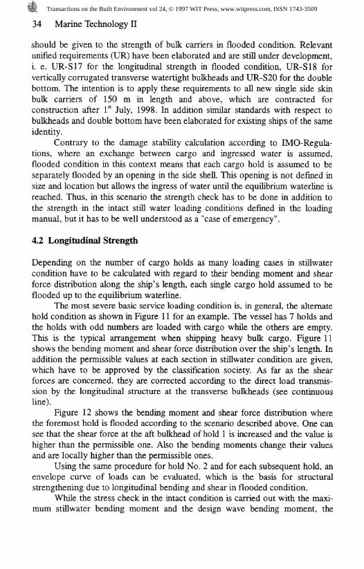
The most severe basic service loading condition is, in general, the alternatehold condition as shown in Figure 11 for an example. The vessel has 7 holds andthe holds with odd numbers are loaded with cargo while the others are empty.This is the typical arrangement when shipping heavy bulk cargo. Figure 11shows the bending moment and shear force distribution over the ship's length. Inaddition the permissible values at each section in stillwater condition are given,which have to be approved by the classification society. As far as the shearforces are concerned, they are corrected according to the direct load transmis-sion by the longitudinal structure at the transverse bulkheads (see continuousline).
Figure 12 shows the bending moment and shear force distribution wherethe foremost hold is flooded according to the scenario described above. One cansee that the shear force at the aft bulkhead of hold 1 is increased and the value ishigher than the permissible one. Also the bending moments change their valuesand are locally higher than the permissible ones.
Using the same procedure for hold No. 2 and for each subsequent hold, anenvelope curve of loads can be evaluated, which is the basis for structuralstrengthening due to longitudinal bending and shear in flooded condition.
While the stress check in the intact condition is carried out with the maxi-mum stillwater bending moment and the design wave bending moment, the
Transactions on the Built Environment vol 24, © 1997 WIT Press, www.witpress.com, ISSN 1743-3509
Marine Technology II 35
check in flooded condition is performed using only 80 % of the Rule wavebending moment. The same procedure is used with regard to shear forces.
If one assumes that in the "intact" condition the stfflwater loads are as highas the wave loads, the strength has to be increased for the flooded condition, ifthe stillwater loads in flooded conditions increase by more than 20 %. This valueis a good approximation.
Shear Forces Shear Forces
A
permissible vaJues A.Puncorrectedcorrected
permissble values F.P.uncorrected
Bending Moments
Fig. 11: Alternate Loading,Intact Condition
Fig. 12: Alternate Loading,One Hold Flooded
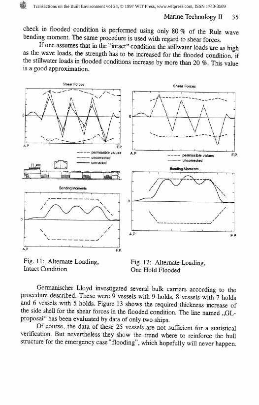
Germanischer Lloyd investigated several bulk carriers according to theprocedure described. These were 9 vessels with 9 holds, 8 vessels with 7 holdsand 6 vessels with 5 holds. Figure 13 shows the required thickness increase ofthe side shell for the shear forces in the flooded condition. The line named ,,GL-proposaT has been evaluated by data of only two ships.
Of course, the data of these 25 vessels are not sufficient for a statisticalverification. But nevertheless they show the trend where to reinforce the hullstructure for the emergency case "flooding", which hopefully will never happen.
Transactions on the Built Environment vol 24, © 1997 WIT Press, www.witpress.com, ISSN 1743-3509
36 Marine Technology II
1.31
1.2
**" 1.1
1.0
9 holds5 holds7 holds
20 40 60 80x/Lpp[%]
100
Fig. 13: Relative Thickness Increase of Side Shellin Flooded Condition, Lumped Values
4.3 Vertically Corrugated Transverse Watertight Bulkheads
While in the aforesaid consequences of a failure of the first barrier namely theside shell has been addressed, the transverse bulkheads as the second barrier arenow discussed. The most severe combinations of cargo and flooding loads are tobe used for the determination of scantlings of each bulkhead depending on thespecified loading conditions defined by the designer:- homogeneous loading conditions;- non-homogeneous loading conditions;- packed cargo conditions (such as steel mill products).
The flooding head hf which is defined in Figure 14, differs from that ofUR S17 (longitudinal strength) because UR S18 is not related to the equilibriumwaterline but to fixed values df as specified below:a) in general:- D for the foremost vertically corrugated transverse bulkhead
0,9 D for the other bulkheadsb) for ships less than 50.000 tdw with B freeboard:- 0,95 D for the foremost vertically corrugated transverse bulkhead
0,85 D for the other bulkheadsTop of ore means the horizontal line after levelling the piled up ore. This
assumed line is the basis for the calculation of the horizontal pressure loadsshown also in Figure 14.
The strength criteria to determine the scantlings (section modulus andlocal plate thickness of corrugation) have been evaluated on the basis ofextensive calculations, carried out by different classification societies to unify asmany global and local structural details as possible.
Transactions on the Built Environment vol 24, © 1997 WIT Press, www.witpress.com, ISSN 1743-3509
Marine Technology II 37
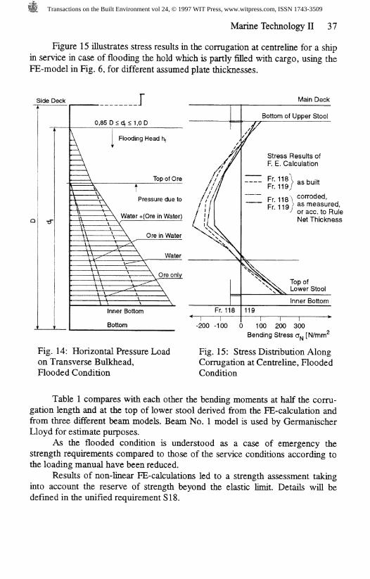
Figure 15 illustrates stress results in the corrugation at centreline for a shipin service in case of flooding the hold which is partly filled with cargo, using theFE-model in Fig. 6, for different assumed plate thicknesses.
Side Deck J Main Deck
•d"
0,85 D < df < 1,0 D\ IA Flooding Head fy ,
i /. \ Top of Ore f / /
iT \\ Pressure due to // • /V ^ \ I /
, A ...\_.\ \A/atcir _L/Ora in \A/otar\ ' / /\\ \ \ water +(Ure in water) : J /: \\ \ v / '\\ \ \ V v\ \i \\ \ \ Oro in Wator ^., \\,>.\\ \ \ ure in water x xxv: \\ \ >: .̂%\
\\ }*c \ XX\\ ^ \ \ Wnter \\\'̂ s \ \ Water \V \ y — — \ ^
: \\ \ \. VA \ \ Ore only• \-\ \ — ̂ --̂ \! \ \ ^\ \\ \ ̂-^ \ \
\ \ \ \\ \ \ \Inner Bottom Fr. 118
Bottom -200 -100 C
Bottom of Upper Stoolif///y
/Stress Results ofF. E. Calculation
Fr 118 V
Fr 118 \ Corroded,\ 23 measured^ or ace. to Rule
Net Thickness
^̂ r<r̂ \X<̂̂ X\̂S%x Top of
\̂\x Lower Stool1 0 U.
119
) 100 200 300Bending Stress o\, [N/mrrf
Fig. 14: Horizontal Pressure Loadon Transverse Bulkhead,Flooded Condition
Fig. 15: Stress Distribution AlongCorrugation at Centreline, FloodedCondition
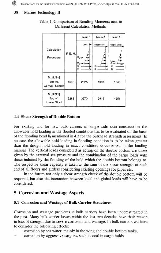
Table 1 compares with each other the bending moments at half the corru-gation length and at the top of lower stool derived from the FE-calcuktion andfrom three different beam models. Beam No. 1 model is used by GermanischerLloyd for estimate purposes.
As the flooded condition is understood as a case of emergency thestrength requirements compared to those of the service conditions according tothe loading manual have been reduced.
Results of non-linear FE-calculations led to a strength assessment takinginto account the reserve of strength beyond the elastic limit. Details will bedefined in the unified requirement SI8.
Transactions on the Built Environment vol 24, © 1997 WIT Press, www.witpress.com, ISSN 1743-3509
38 Marine Technology II
Table 1: Comparison of Bending Moments ace. toDifferent Calculation Methods
Calculation
Procedure
M, [kNm]Half the
Corrug. Length
Mg [kNm]Top of
Lower Stool
F. E. M.
1642
3282
beam 1
Deck
^i-> />
M2-»/-IIB —LB
•<-
<-<-
2025
3370
beam 2
Upper Stool
j
B<-<-
1987
2919
beams
Upper Stool
~l
Lower r~̂Stool L^IBB
1348
4251
4.4 Shear Strength of Double Bottom
For existing and for new bulk carriers of single side skin construction theallowable hold loading in the flooded conditions has to be evaluated on the basisof the flooding head hf mentioned in 4.3 for the bulkhead strength assessment. Inno case the allowable hold loading in flooding condition is to be taken greaterthan the design hold loading in intact condition, documented in the loadingmanual. The vertical loads considered as acting on the double bottom are thosegiven by the external sea pressure and the combination of the cargo loads withthose induced by the flooding of the hold which the double bottom belongs to.The respective shear capacity is taken as the sum of the shear strength at eachend of all floors and girders considering existing openings for pipes etc.
In the future not only a shear strength check of the double bottom will berequired, but also the interaction between local and global loads will have to beconsidered.
5 Corrosion and Wastage Aspects
5.1 Corrosion and Wastage of Bulk Carrier Structures
Corrosion and wastage problems in bulk carriers have been underestimated inthe past. Many bulk carrier losses within the last two decades have their reasonin loss of strength due to severe corrosion and wastage. In bulk carriers we haveto consider the following effects:- corrosion by sea water, mainly in the wing and double bottom tanks,- corrosion by aggressive cargoes, such as coal in cargo holds,
Transactions on the Built Environment vol 24, © 1997 WIT Press, www.witpress.com, ISSN 1743-3509
Marine Technology II 39
wastage due to rough service conditions during cargo loading and dis-charging operations.The corrosion problem in the ballast tanks has been recognised by the clas-
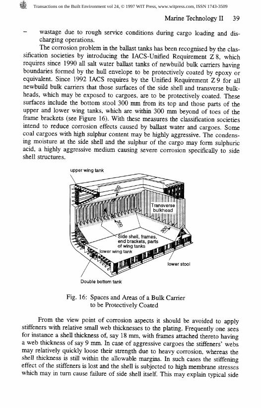
sification societies by introducing the lACS-Unified Requirement Z 8, whichrequires since 1990 all salt water ballast tanks of newbuild bulk carriers havingboundaries formed by the hull envelope to be protectively coated by epoxy orequivalent. Since 1992 IACS requires by the Unified Requirement Z9 for allnewbuild bulk carriers that those surfaces of the side shell and transverse bulk-heads, which may be exposed to cargoes, are to be protectively coated. Thesesurfaces include the bottom stool 300 mm from its top and those parts of theupper and lower wing tanks, which are within 300 mm beyond of toes of theframe brackets (see Figure 16). With these measures the classification societiesintend to reduce corrosion effects caused by ballast water and cargoes. Somecoal cargoes with high sulphur content may be highly aggressive. The condens-ing moisture at the side shell and the sulphur of the cargo may form sulphuricacid, a highly aggressive medium causing severe corrosion specifically to sideshell structures.
upper wing tank
Side shell, frames,end brackets, partsof wing tanks
lower wing tank
lower stool
Double bottom tank
Fig. 16: Spaces and Areas of a Bulk Carrierto be Protectively Coated
From the view point of corrosion aspects it should be avoided to applystiffeners with relative small web thicknesses to the plating. Frequently one seesfor instance a shell thickness of, say 18 mm, with frames attached thereto havinga web thickness of say 9 mm. In case of aggressive cargoes the stiffeners' websmay relatively quickly loose their strength due to heavy corrosion, whereas theshell thickness is still within the allowable margins. In such cases the stiffeningeffect of the stiffeners is lost and the shell is subjected to high membrane stresseswhich may in turn cause failure of side shell itself. This may explain typical side
Transactions on the Built Environment vol 24, © 1997 WIT Press, www.witpress.com, ISSN 1743-3509
40 Marine Technology II
shell failures observed in bulk carriers. It is therefore important that in areassubject to corrosion, the web thickness of the stiffening elements must be ade-quate to that of the stiffened plating.
The classification societies require therefore since 1992 by the Unified Re-quirement S 12 that the web thickness of frames in bulk carriers shall not be lessthan a specified minimum thickness ranging normally from 11,5 - 13 mm, irre-spective whether mild or higher tensile steel is used. The thickness of the lowerframe brackets is required to be at least 2 mm thicker than the above minimumweb thickness for frames.
The above strengthenings are also important from the wastage point ofview. As mentioned above, bulk carrier hold structures are exposed to severetreatment during cargo operation causing physical damages. Heavy grabs may bemoved against frames and brackets and cargo residues are removed from thestructures by special movable hammering equipment". Another case is worth tobe reported, where, as a consequence of loading and discharging big logs, severedeformations of the side framing and framing brackets were observed. Conse-quently, the framing system lost its ability to sufficiently stiffen the side shell,which in turn failed for the reasons explained above, causing hold space flood-ing.
From the corrosion and wastage point of view also some aspects con-cerning the use of higher tensile steel should be considered. The corrosion ratesare also influenced by the stress levels, which may cause higher corrosion ratesfor higher tensile steels. Therefore, hold structures exposed to corrosive cargoesshould be made of mild steel, wherever possible. The application of higher ten-sile steel in bulk carriers should be limited to longitudinal hull structural elementswithin the upper and lower hull flange.
One design aspect of the inner bottom is its stressing by heavy grabs dur-ing cargo discharge. These grabs, having a net weight of some 15 t, are fre-quently moved onto the inner bottom in the final phase of the discharging proc-ess causing thereby severe impact forces. These impact forces can best be ab-sorbed by a ,flexible" inner bottom construction. According to GL's experiencea relatively thick inner bottom in combination with a relative large stiff-ener/girder spacing of say not less than 800 mm has a much better chance tosurvive these impact forces than a relatively thin inner bottom thickness in com-bination with a small stiffener/girder spacing of say 400 - 600 mm.
5.2 Corrosion Additions, Residual Strength of Corroded Structures
The GL rule corrosion addition tk is defined such that it results in a relativelylarge percentage addition for small thicknesses t' and a relatively small percen-tage addition for large thicknesses t', because a mean corrosion rate of say0,2 mm per year means abt. 3 % thickness reduction for a 6 mm thick plate, butonly 0,8 % thickness reduction for a 25 mm thick plate.
The corrosion addition tk ranges therefore generally between ~ 10 - 25 %of the original thickness. For plates designed for local pressures, the absolute
Transactions on the Built Environment vol 24, © 1997 WIT Press, www.witpress.com, ISSN 1743-3509
Marine Technology II 41
corrosion addition tk expressed in terms of millimetres is the same for mild steeland higher tensile steel, because the Rule thickness depends inter alia on thesquare root of the material factor k. Relative to the thickness, the corrosionaddition tk is larger in case of higher tensile steel compared to that for mild steel.This is intended to cover the above mentioned somewhat higher corrosion ratesof higher tensile steels.
The strength concept of the GL Rules is based on the condition that steelrenewal will be required when the average thickness reduction equals the corro-sion allowance tk, i.e. when the net thickness t' = t - tk is reached. The maximumpermissible local thickness reduction is about 20 percent. This means that theGL rules consider also the structural strength in the corroded condition.
For the longitudinal strength standard in the corroded condition it is re-quired that the hull girder moduli are not reduced by more than 10 % due tocorrosion. This means a maximum increase in hull girder bending stress of 10 %,i. e. from 175 to abt. 193 N/mnf, or a safety factor of abt. 1,2 against yielding inthe corroded condition. It can be shown that in case of a 20 % thickness reduc-tion the safety factor against plastic failure of a bottom plate panel and of a bot-tom longitudinal subjected to both hull girder and local bending is still in therange of 1,2 [7].
The Rule requirements for the proof of buckling strength are also based onthe ,riet thickness"-concept by using the thickness t' = t - tk for the bucklinganalysis. For the net thickness the safety factor against buckling must be equal orgreater than 1,0, having in mind that steel renewal becomes necessary when theoriginal thickness is reduced by the corrosion addition tk. This concept also im-plies that the post buckling behaviour provides an additional strength reserve.
6 Concluding Remarks
Severe problems with the ageing world bulk carrier fleet during the past fewyears demanded a review of the strength behaviour and design criteria. Themethods and procedures available for the overall and local strength analysis - asshown in the paper - allow a rational assessment of the structural integrity basedon first engineering principles. This includes aspects such as fatigue strength anddetrimental effects of corrosive environment on crack initiation.
A new aspect will be the requirement of strength analyses in flooded con-dition. The current status has been discussed in the paper, final decisions will betaken by the relevant IACS governing bodies.
It has to be emphasised that even a bulk carrier of an excellent structuraldesign will have problems during the service life if it is not properly maintained.Corrosion and wastage aspects are therefore, most important for the structuralintegrity. Design requirements with respect to fatigue, corrosion additions andprotective coatings can contribute to reduce the problems, proper maintenanceand efficient inspections are essential to control them.
Germanischer Lloyd is fully aware of its responsibility for sound design re-quirements and adequate rule development for safe and efficient bulk carriers, as
Transactions on the Built Environment vol 24, © 1997 WIT Press, www.witpress.com, ISSN 1743-3509
42 Marine Technology II
well as for careful plan approvals including all necessary strength analyses andfor careful surveys during construction and service time. Based on the good ex-perience in the past with a large number of bulk carriers in class, the prospectsfor new generations of bulk carriers are considered as good as far as strengthrequirements are met and maintenance is taken care of.
References
[1] I ACS - International Association of Classification Societies: "Bulk Carriers-Guidelines for Surveys, Assessment and Repair of Hull Structure." London,1994.
[2] H.G. Payer and W. Fiicke: "Rational Dimensioning and Analysis of Com-plex Ship Structures." SNAME Transactions Vol. 102 (1994).
[3] Germanischer Lloyd: "Rules and Regulations, I - Ship Technology, Part 1 -Seagoing Ships, Chapter 1 - Hull Structures." Germanischer Lloyd, Ham-burg 1997.
[4] W. Fricke: "Fatigue Control in Structural Design of Different Ship Types."Proc. of the Vlth Congress of the IMAM, Varna 1993.
[5] Lehmann, E.: "Damages of Ship Structures (in German)." TransactionsSTG, Vol. 84, Springer, Berlin 1990.
[6] W. Fricke, M. Scharrer, H. von Selle: "Integrated Fatigue Analysis of ShipStructures." Proc. of 5th IMDC and Summer Meeting of STG, Delft 1994.
[7] M. Bockenhauer: "Residual Strength of Corroded Structures." Paper pre-sented at the Work Group Meeting of the Tanker Structure Co-operativeForum in Hamburg, October 1988.
Transactions on the Built Environment vol 24, © 1997 WIT Press, www.witpress.com, ISSN 1743-3509


![Acquisition Of Bulk Reo Packages L As Vegas[1]](https://img.pdfslide.net/doc/110x75/547b921ab379597b2b8b4db4/acquisition-of-bulk-reo-packages-l-as-vegas1.jpg)