Embed Size (px)
Citation preview
ORDER
PRE-DEPARTURE CLEARANCE PHASE I PROJECT IMPLEMENTATION PLAN
APRIL 1, 1991
DEPARTMENT OF TRANSPORTATION FEDERAL AVIATION ADMINISTRATION
Distribution: A-w (RD/SM/SE/TR/HT) - 2 ; A-x (AF/AT) - 3 ; Initiated BY: ARD- 3 10
A-FAT-0 (LTD)

RECORD OF CHANGES
FAA
DIRECTIVE NO.
Form
7 0 3 2 . 1 0
C FAA AC 69-2967

FOREWORD
This order provides technical guidance and management direction for the orderly implementation of the Pre-Departure Clearance (PDC) system. This order identifies and describes specific requirements, events, tasks and activities to be accomplished, as well as project responsibilities that are necessary to implement the Project. Management responsibility for this program is assigned to the AircraftICNS System Development Division, ARD- 300.
The goal of this order is to provide a uniform approach for all organizations that have a role in conducting activities necessary to implement any portion of this project.
Acting ~irecvor , Research and Development Service, ARD-1
Page i (and ii)

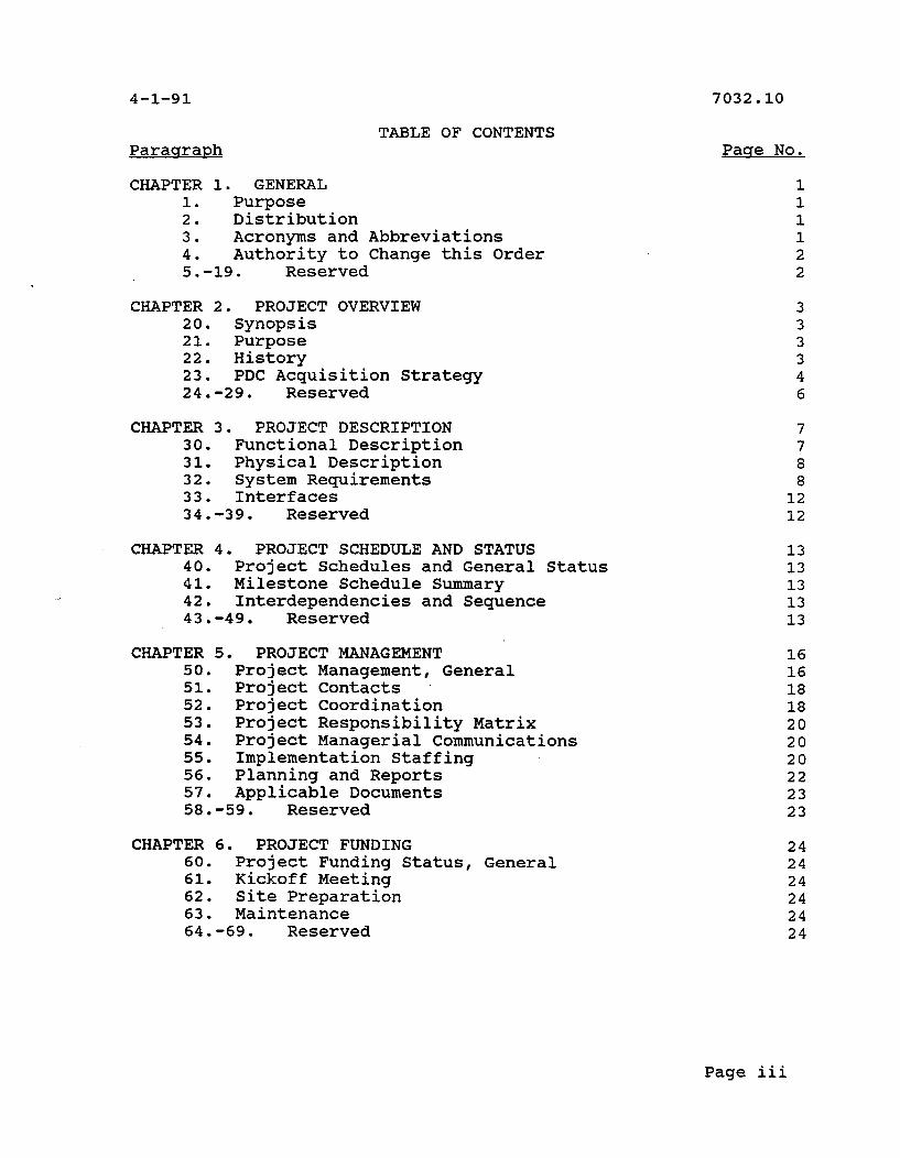
TABLE OF CONTENTS Paraara~h
CHAPTER 1. GENERAL 1. Purpose 2. Distribution 3. Acronyms and Abbreviations 4. Authority to Change this Order 5.-19. Reserved
CHAPTER 2. PROJECT OVERVIEW 20. Synopsis 21. Purpose 22. History 23. PDC Acquisition Strategy 24.-29. Reserved
CHAPTER 3. PROJECT DESCRIPTION 30. Functional Description 31. Physical Description 32. System Requirements 33. Interfaces 34.-39. Reserved
CHAPTER 4. PROJECT SCHEDULE AND STATUS 40. Project Schedules and General Status 41. Milestone Schedule Summary 42. Interdependencies and Sequence 43.049. Reserved
CHAPTER 5. PROJECT MANAGEMENT 50. Project Management, General 51. Project Contacts ,
52. Project Coordination 53. Project Responsibility Matrix 54. Project Managerial Communications 55. Implementation Staffing 56. Planning and Reports 57. Applicable Documents 58.-59. Reserved
CHAPTER 6. PROJECT FUNDING 60. Project Funding Status, General 61. Kickoff Meeting 62. Site Preparation 63. Maintenance 64.-69. Reserved
Pase No.
1 1 1 1 2 2
3 3 3 3 4 6
7 7 8 8 12 12
13 13 13 13 13
16 16 18 18 20 20 20 22 23 23
24 24 24 24 24 24
Page iii
CHAPTER 7. DEPLOYMENT 70. General Deployment Considerations 71. Site Preparation 72. Delivery 73. Installation Plan 74.-79. Reserved
CHAPTER 8. VERIFICATION 80. Hardware Verification 81. System Checkout 82. Contractor Integration Testing 83. Contractor Acceptance Inspection (CAI) 84. Operational Test & Evaluation/Integration 85. Operational Test & Evaluation/Shakedown 86. Joint Acceptance Inspection (JAI) 87. configuration Management (CM) 88.-89. Reserved
CHAPTER 9. INTEGRATED LOGISTICS SUPPORT 90. Maintenance Planning 91. Training 92. Support Tools and Test Eq~ipmer~t 93. Supply Support 94. Vendor Data and Technical Manuals 95. Equipment Removal 96. Facilities 97. Equipment Accountability 98.-99. Reserved
Page iv
CHAPTER 1. GENERAL
1. PURPOSE. This order provides the Project Implementation Plan (PIP) for the Pre-Departure Clearance (PDC) system and presents overall technical guidance and management direction for the orderly implementation of PDC at the respective sites. It identifies activities and schedules required to accomplish this implementation.
2. DISTRIBUTION. This order is distributed at division level to the office of the Director, Research and Development Service, Systems Maintenance, NAS Systems Engineering, and Air Traffic Plans and Requirements Services, and the Office of Training and Higher Education; to branch level in the regional Airway Facilities and Air Traffic divisions; and Air Traffic field off ices.
3. ACRONYMS AND ABBREVIATIONS. The following abbreviations and acronyms are
ACARS
ADNS AMS APMT ARINC ARTCC AT ATC ATCT ATN CAI CCB CD CDRL CM CMS CSA DPA DRR ECP FAA FCA FCI FDIO FE FRDF FSP FTS IFR ILSP
used in this order:
Aircraft Communications Addressing and Reporting System ARINC Data Network Service ARINC Maintenance Service Associate Program Manager For Test Aeronautical Radio Incorporated , , Air Route Traffic Control Center Air Traffic Air Traffic Control Airport Traffic Control Tower Aeronautical Telecommunication Network Contractor Acceptance Inspection Configuration Control Board Clearance Delivery Contract Data Requirements List Configuration Management Communications Management System Configuration Status Accounting Delegation of Procurement Authority Deployment Readiness Review Engineering Change Proposal Federal Aviation Administration Functional Configuration Audit Functional Configuration Inspection Flight Data Input Output Field Engineering Facility Data Reference File Flight Strip Printer Federal Telecommunications System Instrument Flight Rules Integrated Logistic Support Plan
Chap 1 Par 1 Page 1
JAB JAI ME NAILS NAS NCP OATS OCD ORD OT&E PA PC PCA PC1 PDC PIP RALA RCU SA SEI SSS TOR UPS
Joint Acceptance Board Joint Acceptance Inspection Maintenance Engineering National Airspace Integrated Logistics Support ~ational Airspace System NAS Change Proposal Office Automation Technology and Service Operation Capabilities Demo Operational Readiness Demonstration Operational Test & Evaluation Project Authorization Personal Computer Physical Configuration Audit Physical Configuration Inspection Pre-Departure Clearance Project Implementation Plan Registered Automatic Line Adapter Remote Control Unit System Administrator System Engineering and Integration System/Segment Specification Technical Officer Representative Uninterruptible Power Supply
4. AUTHORITY TO CHANGE THIS ORDER. The Director, Research and Development Service, ARD-1 may issue changes to this order necessary to manage and implement the project which do not affect policy, delegate authority, or assign responsibility.
5. -19. RESERVED.
Page 2 Chap 1 Par 3
CHAPTER 2. PROJECT OVERVIEW
20. SYNOPSIS. Today's Air ~raffic Control (ATC) clearance delivery process can be cumbersome, labor intensive in terms of controller voice-communications workload, and susceptible to human error. This is particularly true at high density facilities where upwards of 1,000 clearances are delivered daily. Also, frequency congestion with its consequent blocked and garbled communications has reached highly undesirable levels at many facilities.
PDC will assist the Airport Traffic Control Tower (ATCT) clearance delivery position in relaying departure clearances to flight crews via data link. Data link delivery of clearances will relieve much of the voice congestion on the ATCT clearance delivery frequency by eliminating voice clearance delivery to airlines participating in the program.
21. PURPOSE. The PDC system provides a solution to voice communications problems by using digital data communications instead of voice to relay departure clearances to aircrews. The PDC system can be used by tower personnel to compose clearances for data link delivery based upon information contained in the departure flight strips plus local operational instructions selectable from menu lists. After reviewing and appending any local information, the clearance is transmitted from the PDC system to participating airline operations host computers. The airlines then take responsibility to deliver the clearance directly to the appropriate aircraft utilizing Aircraft Communications Addressing and Reporting System (ACARS) data link or by delivery to departure gate printers. This eliminates the need for a voice contact with the tower for clearance delivery to the flight crew. The PDC system will communicate directly with the airline operations computer to deliver clearances and will not affect in any way the FDIO system or flight strip printing in the tower cab.
22. HISTORY. The MITRE Corporation developed an experimental tower workstation under the sponsorship of the Federal Aviation Administration (FAA) to issue clearances in digital form. The workstation was installed in three towers: Dallas/Ft. Worth (DFW), Chicago OqHare (ORD), and San Francisco (SFO).
In July 1989, the DFW system began operation with American Airlines as the sole participant. American uses ACARS data link as the delivery mechanism to the cockpit. All of American's DFW departures were eligible to participate, amounting to approximately 400 flights per day.
In December 1989, the ORD system began operating with both American and United Airlines participating. The majority of
Chap 2 Par 20 Page 3

United's fleet does not have data link displays suitable for presentation of the clearance message; therefore, a hybrid delivery system is used by United. The PDC message is received at the gate podium printer for flights not appropriately equipped to receive the message via data link. For flights with the appropriate equipment, the PDC message is accessed by the crew and displayed via a touch display input/output (110) device in the cockpit. All of American's and United's ORD departures are eligible to participate, amounting to approximately 700 flights per day.
Since then both Delta and USAir have also begun participation. Delta does not make extensive use of data link due to limitations of the data link avionics in the fleet. For now Delta's approach is to deliver the PDC message via gate podium printers for all flights. Approximately 95% of USAir's fleet has data link equipment suitable for display of the PDC message. Therefore USAir uses only data link for delivery of the digital PDC message. The addition of these airlines have had the most impact at DFW, raising the number of clearances issued using PDC to approximately 600 per day.
SF0 became the third PDC demonstration site in September of 1990. All four participating air carriers operate from SFO, which uses PDC to issue more than 200 clearances per day.
23. PDC ACQUISITION STRATEGY. Key aspects of the acquisition of the PDC system are as follows:
a. The FAA plans to implement PDC in two phases through a turnkey services contract. The first phase will culminate in the installation of 30 operational systems within approximately six months from the date of contract award. This phase will not add substantial new functionality to the experimental system, but will move the software to a homogenous hardware platform. The initial three experimental systems that have been in operation during the last year will be replaced as part of the thirty. The majority of the PDC hardware, including AT&T workstations, will be procured using th'e FAA office ~utomation Technology and Service (OATS) contract. Maintenance for items purchased through the OATS contract will also be procured at the same time.
b. The first phase of the PDC implementation will remain in operation for approximately one year. During this time, a second phase will be conducted in which the PDC software will be subjected to a complete evaluation and development cycle which will ensure software reliability and functionality according to user requirements. Additional enhancements which will allow PDC to transition to the future data communications environment will also be included, after which all PDC systems will be upgraded with the new software from this second phase development. The PDC system hardware is expected to remain the same during both
Page 4 Chap 2 Par 22
phases, although the cold standby system in the first phase will become a redundant system backing up the operating PDC system in Phase 11. Eventually, the enhancements of the second phase will allow direct data communications between the clearance delivery controller and the flight crew in the cockpit, allowing much greater clearance delivery control and flexibility in issuing clearance revisions.
c. The equipment and services to be obtained utilizing the PDC contract are as follows:
Tower Emipment - Tower Cab. (a) AT&T 502 terminal with keyboard (2)
(b) Short Haul modem (2)
Tower Eauipment - Tower Equipment Room.
(el Model 122 to allow
. . AT&T 6386/25 Personal Computer (PC) (2)
1.44 MB internal'disk drive 182 MI3 unformatted internal hard disk Internal cartridge-tape drive 8 MB RAM Multisync GS2A monochrome monitor 10 MHz Starlan network access board
Uninterruptible Power Supply (UPS)
Omni 48 modem (2)
Short Haul modem (2)
Registered Automatic Line Adapter (RALA), switching from dedicated to dial backup lines
Cables FDIO RCU to AT&T PC (up to 4)
Power Strip
Rack
RS-232 card with eight ports
RS-422 card with four ports
AT&T nix System V/386 version 3.2.2
Chap 2 Par 23 Page 5
(3) Installation.
(a) Two dedicated four-wire data circuits
(b) PDC system
(4) Software. The PDC experimental software that was developed by MITRE will be ported from the PDC demonstration system hardware platform to the ATtT hardware by the PDC contractor. All software that is related to changes in supporting hardware (e.g., 8-port asynchronous card instead of 3Com Ethernet) must also be changed. Technical support will be provided by MITRE.
(5) Maintenance Suwwort. Aeronautical Radio Incorporated (ARINC) is responsible for all maintenance support for PDC, and will be the single point of contact for maintenance of both hardware and software. ARINC is responsible for ensuring that a failure in any PDC system component within their control is corrected within four hours of notification. ARINC is also responsible for taking corrective action for system components outside their control, such as an interruption in Telco services. Any hardware maintenance required through the OATS contract will be arranged and supervised by ARINC. A cold backup system will be ready to be switched over in the event of a failure by the running system. This system will remain in operation until ARINC can arrange hardware-maintenance through AT&T.
(6) Traininq. operation and user training will be presented on-site by ARINC. Each site will be trained following system installation. A capability to conduct ongoing training will be provided by ARINC for those personnel that were not trained during the initial training session. ARINC will have completed internal training for their support personnel before installation. This training will include maintenance and operation procedures.
24.-29. RESERVED.
Page 6 Chap 2 Par 23

CHAPTER 3. PROJECT DESCRIPTION
FUNCTIONAL DESCRIPTION.
a. The PDC system can be used by tower personnel to compose clearances for data link delivery based upon information contained in the departure flight strips plus local operational instructions selectable from menu lists. Data from the departure flight strip arriving in the tower on the Flight Data Input/Output (FDIO) are stored and displayed to the tower Clearance Delivery (CD) controllers on the PDC terminal. After reviewing and appending any local information, the departure clearance is transmitted from the PDC system to participating airline operations host computers. The airlines then take responsibility to deliver the clearance directly to the appropriate aircraft utilizing ACARS data link or by delivery to departure gate printers. This eliminates the need for a voice contact with the tower for clearance delivery to the flight crew. The PDC system will communicate directly with the airline operations computer to deliver clearances and will not affect in any way the FDIO system or flight strip printing in the tower cab.
Q
b. The PDC system can be broken up into six functional areas :
(1) Human Machine Interface. *All CD Controller or System Administrator (SA) inputs will be received by this function. Requests will be passed to the appropriate function. Displays, menus, and forms will be also be generated by the function and presented to the controller or SA.
(2) PDC Data Processor. This function will receive all inputs from the FDIO and select clearances for participating airlines. Input from the CD controller will be validated, appended to the clearance and then sent to the airline host. Acknowledgements from airlines for clearances will be recorded and the clearance queue will be updated.
(3) PDC Database. The PDC Database function will store all clearances, debugging data, network data, and site specific data. This data can be retrieved for startup, queries, and message archiving.
(4) Messase Archival. All clearances that were sent to the airline host computers must be stored for a period of 15 days. These messages must be archived to tape on a regular basis.
(5) Svstem Services. System services will provide the means for startup, shutdown, security, change to second clearance
Chap 3 Par 30 Page 7
position, error reporting, performance monitoring, as well as other necessary functions.
(6) Data Extraction. Data Extraction will allow clearances to be retrieved for a particular aircraft, an airline, or a selected day. The .data will be formatted and a means or procedure will be provided for printing this data.
31. PHYSICAL DESCRIPTION. Figure 3-1 depicts the PDC system components. The components that will be housed in the ATCT facility are enclosed in the dark black outline resembling a tower. Only the PDC terminal(s) will reside in the tower cab. The PDC system (ATtT 386 workstation) will receive the clearances through a one way tap on each line that drives the Flight Strip Printers (FSPs) that are in the cab. The tap of up to four FSP lines will be accomplished with a connection between the FDIO Remote Control Unit (RCU).and the PDC equipment. This connection does not affect normal operation of any FDIO system components. There will be a cold backup system in the equipment room for switch over if the operating PDC system fails. The PDC terminal in the cab will provide the means for the clearances to be reviewed and have local dafa appended prior to data link delivery to the airlines. Once a clearance is complete it will be sent via a dedicated Telco line to an ARINC Data Network Service (ADNS) facility, where it is forwarded to the airline host computers and on to the appropriate flight crew. Figure 3-2 shows the interconnection between the PDC components and how they will interface through the,Telco system to the ADNS facilities.
32. SYSTEM REOUIREMENTS. System requirements that have been determined for the Phase I PDC system are listed below:
a. Computer must be. located outside of tower cab.
tap. b. System must receive data from FDIO as a passive
c. Flight numbers of all unprocessed flights must be displayed.
d. Controller must be able to append information to clearances.
e. Clearance can't be removed until an acknowledgment is received from the airline host.
f. Clearances and airline acknowledgments must be stored for a period of 15 days.
g. Software must be the same for all 30 locations.
Page 8 Chap 3 Par 30
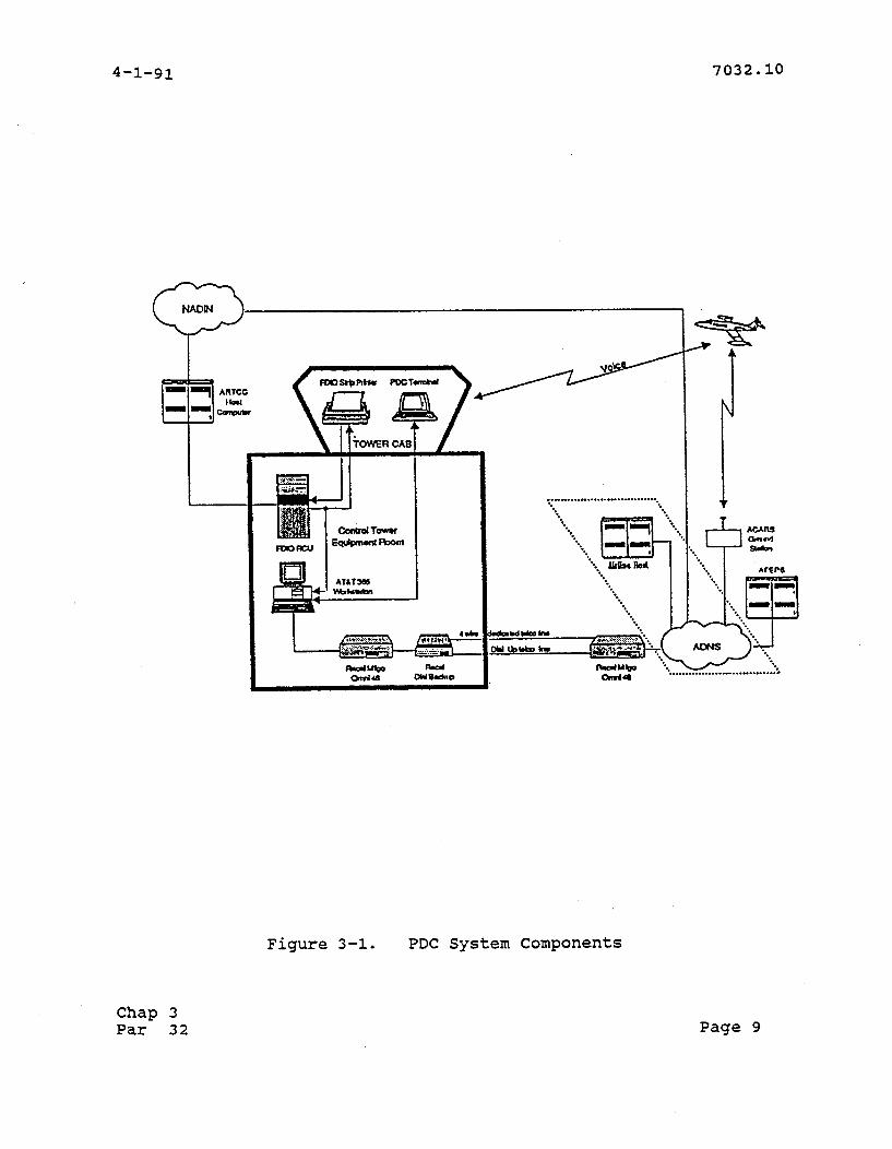
Figure 3-1. PDC System Components
Chap 3 Par 32 Page 9
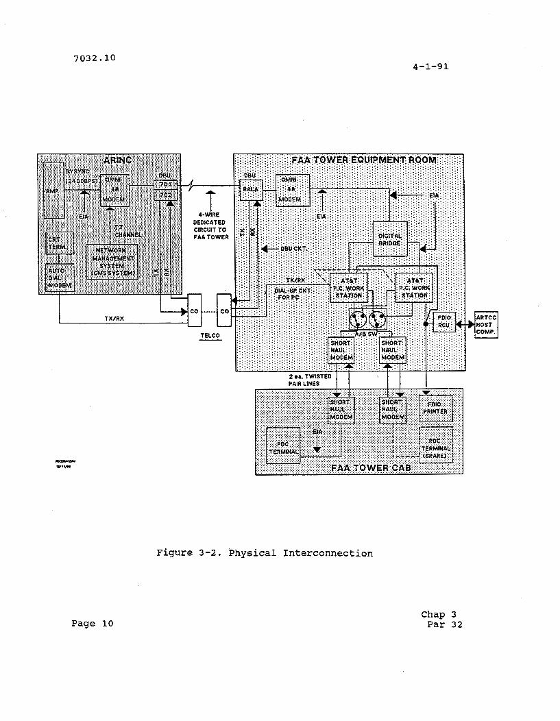
Figure 3-2. Physical Interconnection
Page 10 Chap 3 Par 32
4-1-91
h. A backup system must be provided.
i. Controller input must be validated.
j. Airline acknowledgement messages must be tracked.
k. Automatic mode processing of clearances must be provided.
1. Flights must be posted with the same time as the flight strip printer.
m. Flights must be posted in order of receipt, except for those associated with revised flight strips.
n. Lists should contain multiple columns.
o. Workstation must be capable of at least two modes of operation: flight select and flight clearance generation.
p. Screen should display an image of the actual flight strip for the selected flight.
q. Current local time must be displayed.
r. The display must alert controller when airline is unable to deliver a departure clearance
s, A timeout indication must be provided if a transmitted clearance is not acknowledged.
t. Abnormal acknowledgements from airlines must be handled.
u. Clearance data to the ADNS interface must be staged for delivery to airline operations computers.
v. Provision to purge data from the database must be provided.
w, The screen must display a status area used to display status conditions related to the transmission of clearances. Status messages must be accompanied by a aural alert from the terminal.
x. Performance must be monitored via system statistics.
. Processing throughput must be throttled to match communicat~ons.
Chap 3 Par 32 Page 11
z . Capability to start and stop the system must be provided.
aa. Capability to produce and deliver system error reports must be provided.
bb, Provision must be provided for logon authorization.
cc. Ability to switch from one PDC.termina1 to the other PDC terminal must be provided.
33. INTERFACES.
a. Communications Channel Interface.
(I) PDC Computer to ADNS. The ADNS provides the connectivity to the host computers of the participating airlines. Individual clearance messages are transmitted to the airline hosts and acknowledgment messages are received via this interface. Both the PDC computer and the ADNS use a Bisynchronous protocol.
(2) PDC Computer to PDC Terminal. All user interaction will be transferred through this interface. ~ndividual clearances will be updated.
(3) FDIO to PDC Com~uter. All flight strip data will enter into the PDC system through the FDIO interface.
b. Physical Interface.
(1) PDC Computer to ADNS. The PDC computer uses an asynchronous interface to communicate with the RALA. The RALA uses a four wire circuit to communicate with ADNS. The interface between the PDC computer and the RALA is RS-232.
(2) PDC Computer to PDC Terminal. The PDC computer uses an asynchronous interface to communicate with the PDC terminal. Short haul modems are at each end to allow communications between the two devices at longer distances. The interface is RS-232.
(3) FDIO to PDC Computer. The PDC computer uses a one way asynchronous interface to receive data from the FDIO. The interface is RS-422. NAS Change Proposal (NCP) #I3590 has been generated and was approved on February 28, 1991 for this connection.
34.-39. RESERVED.
Page 12 Chap 3 Par 32
CHAPTER 4. PROJECT SCHEDULE AND STATUS
40. PROJECT SCHEDULES AND GENERAL STATUS. The project schedule for the PDC system phase I is shown in Figure 4-1.
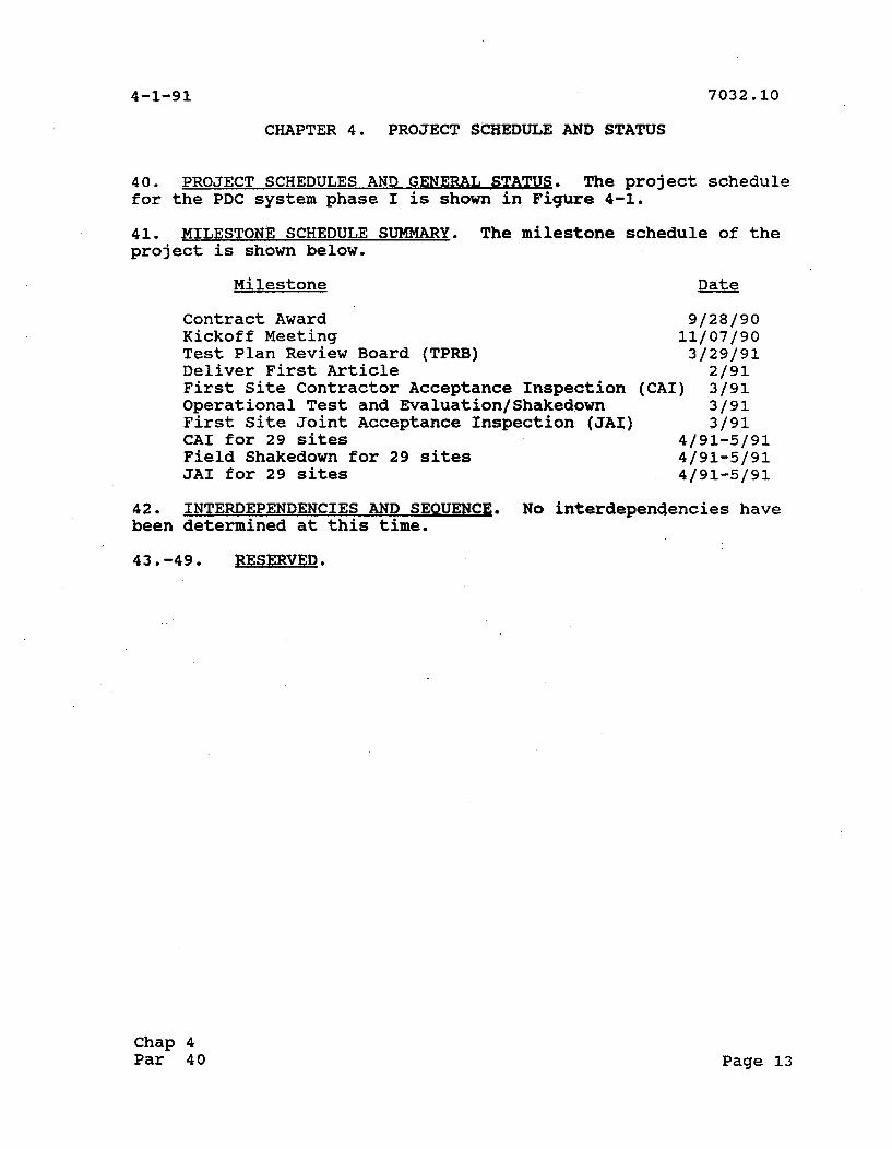
41. MILESTONE SCHEDULE SUMMARY. The milestone schedule of the project is shown below.
Milestone Date
Contract Award 9/28/90 Kickoff Meeting 11/07/90 Test Plan Review Board (TPRB) 3/29/91 Deliver First Article 2/91 First Site Contractor Acceptance Inspection (CAI) 3/91 Operational Test and Evaluation/Shakedown 3/91 First Site Joint Acceptance Inspection (JAI) 3/91 CAI for 29 sites 4191-5/91 Field Shakedown for 29 sites 4191-5/91 JAI for 29 sites 4191-5/91
42. INTERDEPENDENCIES AND SEQUENCE. No interdependencies have been determined at this time.
43.-49. RESERVED.
Chap 4 Par 40 Page 13

Activity
Contract Award
Kickoff Meeting
Site Survey
Rack Installation
Site Survey Approval
Leased Line Installation
Local Loop Installation
Site Preparation
Program Implementation Plan (PIP) Prepare PIP Review/Comment Final PIP
-
NAILS Prepare ILSP Review/Comment NAILSMT Final ILSP
System Installation DFW SF0 ORD PIT ATL LAX DEN BOS STL JFK LGA DCA MIA CLT MSP EWR BWI DTW MEM MCO PHL RDU IAD SLC PHX BNA SEA IAH LAX
Training DFW SF0 ORD LAX DEN PIT ATL BOS STL JFK LGA DCA MIA DTW MSP EWR BWI MEM MCO PHL CLT RDU SLC PHX BNA SEA IAH LAS IAD
Start End
Figure 4-1. Project Schedule.
Page 14 Chap 4
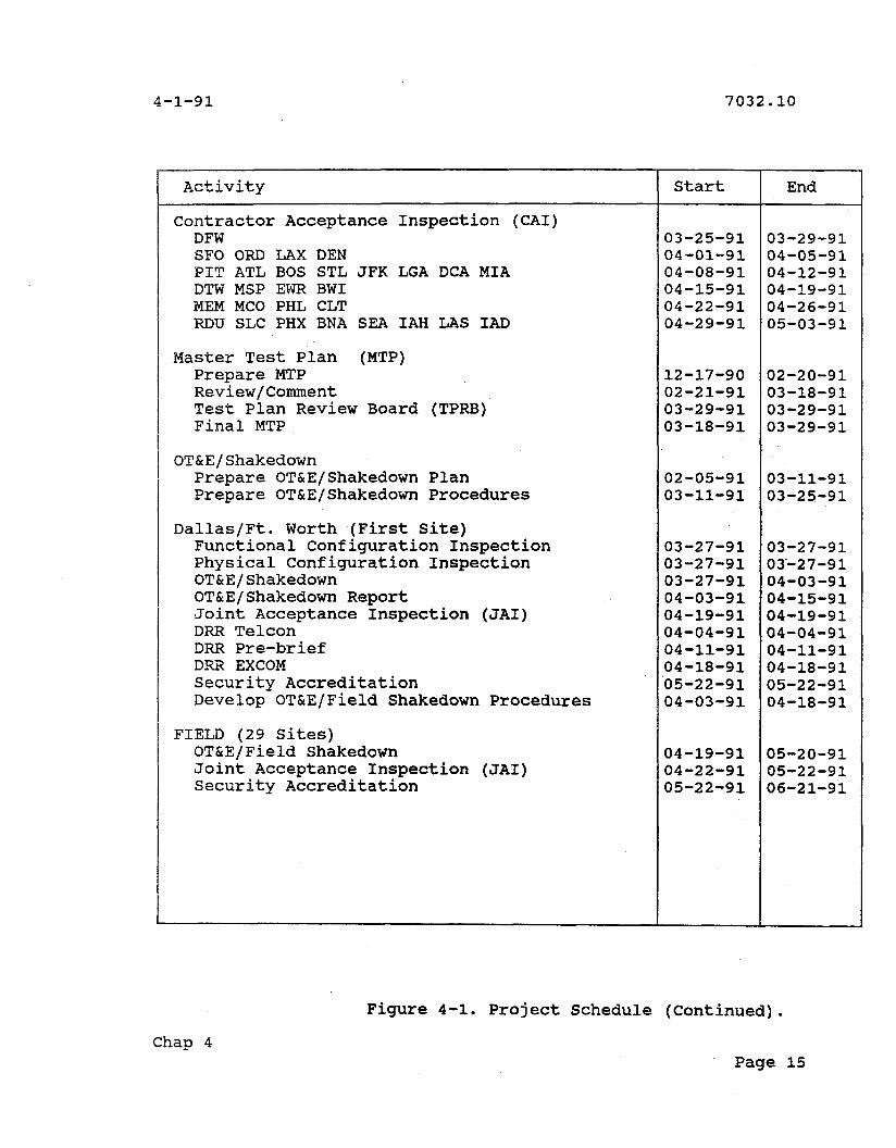
Activity
Contractor Acceptance Inspection (CAI) DFW SF0 ORD LAX DEN PIT ATL BOS STL JFK LGA DTW MSP EWR BWI MEM MCO PHL CLT RDU SLC PHX BNA SEA IAH
DCA MIA
LAS IAD
Master Test Plan (MTP) Prepare MTP Review/Comment Test Plan Review Board Final MTP
(TPRB)
Prepare OT&E/Shakedown Plan Prepare OT&E/Shakedown Procedures
Dallas/Ft. Worth (First Site) Functional Configuration Inspection Physical Configuration Inspection OT&E/Shakedown OT&E/Shakedown Report Joint Acceptance Inspection (JAI) DRR Telcon DRR Pre-brief DRR EXCOM Security Accreditation Develop OT&E/Field Shakedown Procedures
FIELD (29 Sites) OT&E/Field Shakedown Joint Acceptance Inspection (JAI) Security Accreditation
Start End
Chap 4
Figure 4-1. Project Schedule (Continued).
Page 15
CHAPTER 5. PROJECT MANAGEMENT
50. PROJECT MANAGEMENT, GENERAL. The project management organization at the FAA Washington Headquarters, regions, and facilities that will be responsible for the successful implementation of the PDC system are presented in the following paragraphs. Their respective areas of responsibilities in the implementation are described.
a. FAA Washinaton Headauarters Proiect Manaqement.
(1) Director, Research and Development Service (ARD- a. ARD-1 has joint responsibility with Systems Maintenance Service, ASM-1, and Air Traffic Plans and Requirements Service, ATR-1 for the Pre-Departure Clearance Program.
(2) AircraftICNS Svstem Division Manaqer (ARD-3001. ARD-300 has overall management responsibility for the implementation.
(3) PDC Proaram Manaaer (ARD-3101. A member of the Aircraft/CNS System Development Division has been designated PDC Program Manager. The Program Manager will be responsible for developing, coordinating, and implementing Phase I and Phase I1 of PDC. The implementation responsibilities of the program manager are to ensure that the PDC system is ready for deployment and that the FAA will be ready to receive, operate, and provide life-cycle support for the PDC system when deployed.
(4) Proqram Manaaer International Telephone (ASM-300). ASM-300 will coordinate requirements of local loop phone lines with each region.
(5) Contractina Officer, Defense Commercial Communications Office (DECCO). The contracting officer will convert the program requirements into contractual documents and perform contract management activities to assure that the terms of the contract are met. The contracting officer will be the only person authorized to make changes that will affect prices, deliverables, and/or schedules.
(6) Svstem Enaineerina and Intearation (SEI) Contractor. The SEI contractor is involved in the Deployment Readiness Review (DRR) process, support of testing and configuration management.
(7) Proiect Suwwort Contractor. The project support contractor will:
(a) Provide technical guidance and direction, through ARD-310, to the PDC contractor within the scope of the
Page 16 Chap Par
contract.
(b) Perform systems engineering and analysis.
(c) Develop and maintain the Project Implementation Plan.
(d) Serve as a member of the DRR Team.
(e) communicate program information and status.
(f) Develop and maintain the Master Test Plan.
(8) Software Im~lementation Sumort Contractor. The software implementation support contractor will provide the following:
(a) provide assistance to PDC contractor on porting of software from SUN platform to AT&T platform.
(b) Serve as a member of the DRR Team.
b. Resional Project Manasement. Regional Project Management will provide the following:
(1) Coordination of the installation of the local loop telephone lines (two dial back-up lines and one maintenance line). This will include ordering and support of the installation.
(2) Conduct JAI with facility management.
(3) Coordination of Site Survey and review/approval of Site Survey Report.
(4) Facility Reference Data File (FRDF) shall be established by the Airway Facilities sector personnel with the appropriate information provided by the regional F&E personnel.
c. Facility Project Manaqement. Facility Project Management will be responsible for:
(1) The installation of the local loop telephone lines (two dial back-up lines and one maintenance line).
(2) Participation in CAI with the PDC contractor.
( 3 ) Organization of Cadre training for Clearance Delivery controllers.
( 4 ) Conducting OT&E/Field Shakedown testing using procedures developed by the ASM-410.
Chap 5 Par 50 Page 17
(5) Coordination of site preparation.
(6) Participation in JAI with Regional Management.
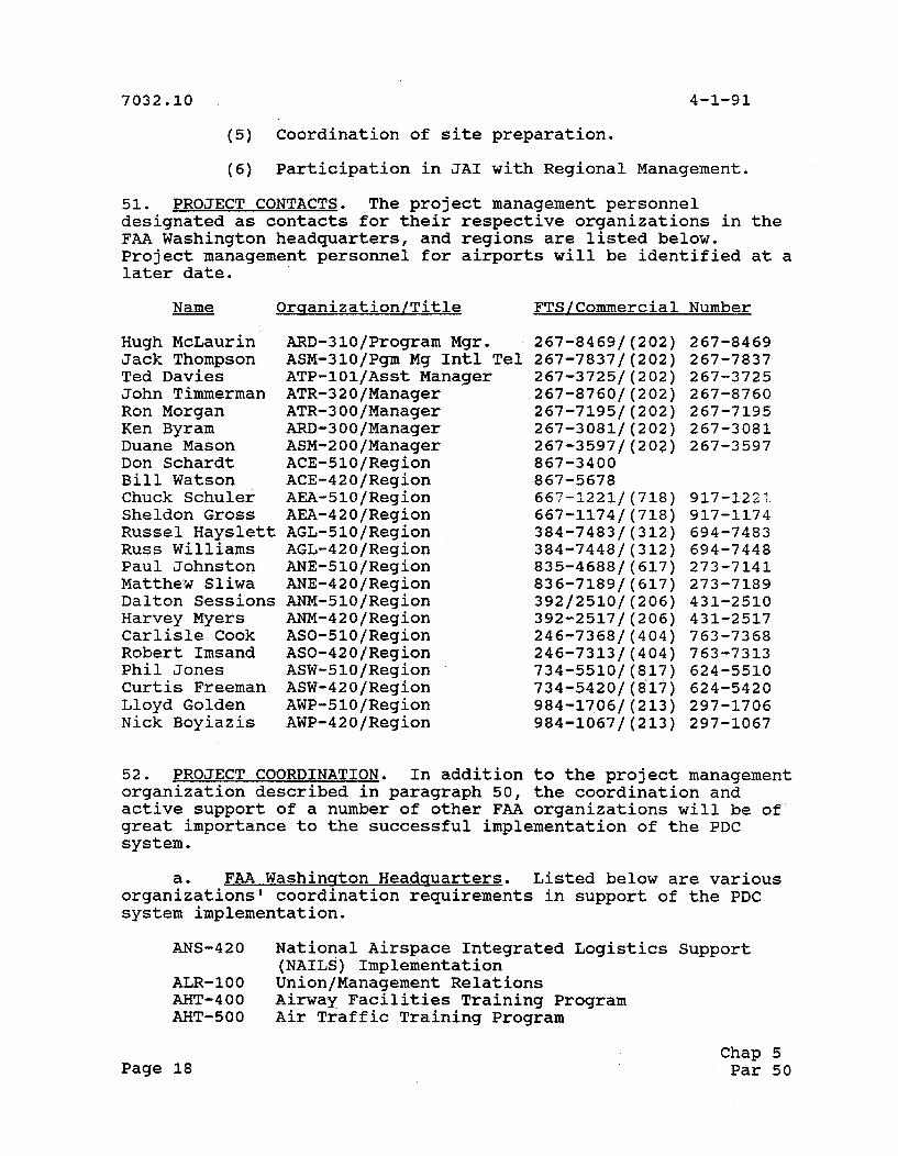
51. PROJECT CONTACTS. The project management personnel designated as contacts for their respective organizations in the FAA Washington headquarters, and regions are listed below. Project management personnel for airports will be identified at a later date.
Name Orqanization/Title FTS/Commercial Number
Hugh McLaurin Jack Thompson Ted Davies John Timmerman Ron Morgan Ken Byram Duane Mason Don Schardt Bill Watson Chuck Schuler Sheldon Gross Russel Hayslett Russ Williams Paul Johnston Matthew Sliwa Dalton Sessions Harvey Myers Carlisle Cook Robert Imsand Phil Jones Curtis Freeman Lloyd Golden Nick Boyiazis
ARD-310/Program Mgr. ASM-310/Pgm Mg Intl Tel ATP-lOl/Asst Manager ATR-320lManager ATR-300lManager ARD-3OO/Manager ASM-200lManager ACE-5101Region ACE-42OlRegion AEA-510/Region AEA-420lRegion AGL-510lRegion AGL-420lRegion ANE-51O/Region ANE-420lRegion ANM-5101Region ANM-420/Region ASO-5101Region ASO-42OlRegion ASW-510lRegion ASW-420lRegion AWP-510lRegion AWP-420lRegion
52. PROJECT COORDINATION. In addition to the project management organization described in paragraph 50, the coordination and active support of a number of other FAA organizations will be of great importance to the successful implementation of the PDC system.
a. FAA Washinaton Headquarters. Listed below are various organizations' coordination requirements in support of the PDC system implementation.
ANS-420 National Airspace Integrated Logistics Support (NAILS) Implementation
ALR-100 UnionIManagement Relations AHT-400 Airway Facilities Training Program AHT-500 Air Traffic Training Program
Page 18 Chap 5 Par 50
Field Development Program Policy and Requirements Branch NAS System Engineering Service Office of Civil Aviation Security Air Traffic Rules and Procedures Air Traffic Advanced Automation System Requirement AircraftlCNS System Development Telecommunications Ops & Admin
b. FAA ~echnical Center.
(1) Automation Division [ACN-100). ACN-100 has the Test and Evaluation responsibilities as defined in Order 1810.4. As the Associate Program Manager for Test (APMT), responsibilities include:
(a) Review of OT&E/Shakedown test requirements, plans, and procedures.
(b) Monitor OT&E/Shakedown tests.
(c) Review all OT&E/Shakedown test reports.
(d) Review field shakedown test requirements, plans, procedures, and reports.
(e) Monitor Field Shakedown tests.
(f) Jointly prepare and update the Project Master Test Plan with the Program Manager.
(g) Provide updates of available test results during DRR telcons.
(2) National Automation Ensineerins Field Sumort Division (ASM-400). ASM-400 has the responsibilities as defined in Order 1810.4:
(a) Member of TPRB.
(b) Reviews Project MTP and Project MTP requirements.
(c) Prepares OT&E/Shakedown test requirements, plans, procedures, and reports in coordination with ATR.
(d) Approves OT&E/Shakedown test requirements, plans, procedures, and reports in coordination with ATR.
(el Directs and conducts OT&E/Shakedown tests as applicable to ASM OTCE requirements.
Chap 5 Par 52 Page 19

(f) Provides personnel for performing and/or monitoring the conduct of OT&E/Shakedown test.
(g) Conducts OT&E/Shakedown data analysis.
(h) Provides a deployment recommendation that represents both ASM and ATR organizations conclusions based on OT&E/Shakedown test and evaluation results in support of tQe DRR process.
(i) Monitors Field Shakedown tests.
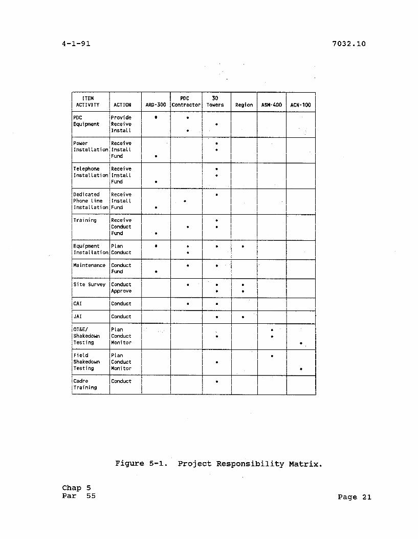
5 3 . PROJECT RESPONSIBILITY MATRIX. The matrix presented in Figure 5-1 shows the organizational responsibilities and significant functions to be performed during the PDC implementation.
54. PROJECT MANAGERIAL COMMUNICATIONS. The PDC Program Office will manage the project using the following communications means:
a. National PDC Kickoff Meetinq. The program office will host a National PDC Kickoff Meeting after contract award. Personnel who may attend the conference are the program office, other headquarters offices, regional engineering offices, participating airports facility management, and other personnel as may be required.
b. Weeklv Status Meetinas. The program office will conduct weekly status meetings with the PDC contractor and other .personnel required to discuss specific topics.
c. Coordination between Program Office and the ~egions/Towers is performed by the Air Traffic focal point. Regular telephone conversations and memorandums provide the means for this coordination.
5 5 . IMPLEMENTATION STAFFING. ARD-310 is responsible for identifying staffing requirements. However, there are no unique or peculiar staffing requirements associated with the PDC system.
2
Page 20 Chap 5 Par 52
1 ITEM 1 I ACTIVITY I ACTION ARD-300
1 PDC /provide 1 IEquipment [Receive 1 I j I n s t a l l I I
I~quipment /p lan I 1 I n s t a l LationIConduct I -
I
Power
/ Telephone 1 ~ e c e i v e 1 I l n s t a l l a t i o n l I n s t a l l I
I 1 Fund I I
/ s i t e Survey /conduct 1 I I ~ p p r o v e I
Receive
Dedicated
I Ins ta l la t ion1 1ns ta l I
I 1 Fund I
Receive
Figure 5-1. Project Responsibility Matrix.
/ p h o n e l i n e I ~ n s t a l l / 1 Ins ta lLat ionI Fund I
I 1 CAI /conduct 1 -
Chap 5 Par 55
JAI
Page 21
Conduct
I I 1 OT&E/ 1~Lan I 1 Shakedown 1 Conduct I Testing Monitor
I I l ~ i e l d IPlan 1 1 Shakedown 1 Conduct I [Test ing [Monitor I
Organizations with assigned responsibilities are expected to accomplish their tasks with existing resources. The contractor will provide maintenance for the life-cycle of the system.
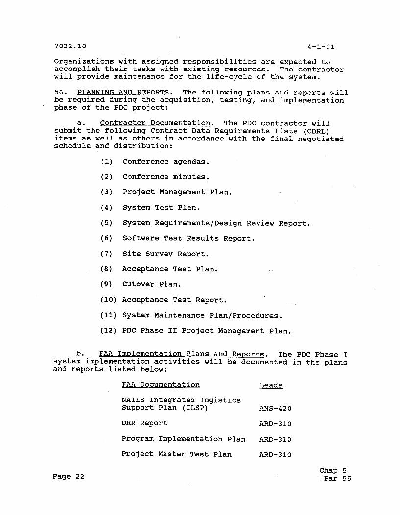
56. PLANNING AND REPORTS. The following plans and reports will be required during the acquisition, testing, and implementation phase of the PDC project:
a. Contractor Documentation. The PDC contractor will submit the following Contract Data Requirements Lists (CDRL) items as well as others in accordance with the final negotiated schedule and distribution:
(1) Conference agendas.
(2) Conference minutes.
(3) Project Management Plan.
(4) System Test Plan.
(5) System Requirements/Design Review Report.
(6) Software Test Results Report.
(7) Site Survey Report.
(8) Acceptance Test Plan.
(9) Cutover Plan.
(10) Acceptance ~ e s t Report.
(11) System Maintenance Plan/Procedures.
(12) PDC Phase I1 Project Management Plan.
b. FAA Im~lementation Plans and Reports. The PDC Phase I system implementation activities will be documented in the plans and reports listed below:
FAA Documentation Leads
NAILS Integrated logistics Support Plan (ILSP) ANS-420
DRR Report ARD-3 10
Program Implementation Plan ARD-310
Project Master Test Plan ARD-310
Page 22 Chap 5 Par 55
Security Risk Analysis ARD-310
JAI Report Regions/ Airway Facilities
Training Requirements AHT-400/500
Maintenance Requirements ASM-240
Facility Reference Data File Regions/ Airway Facilities
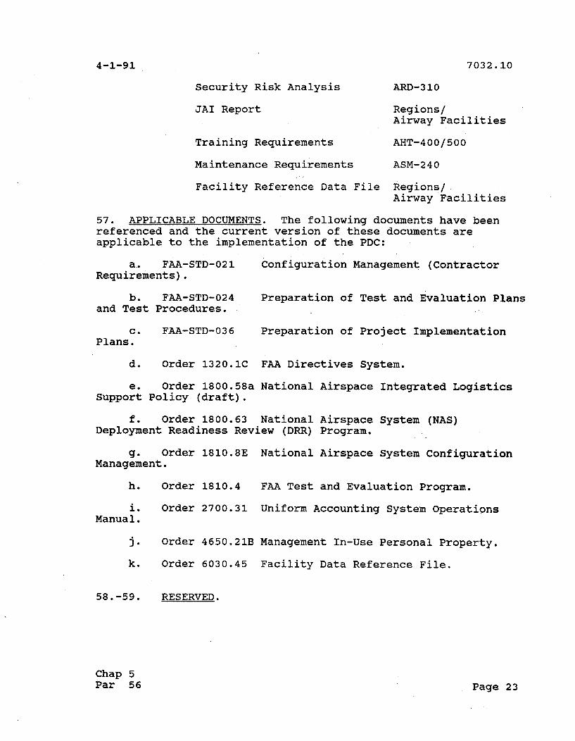
57. APPLICABLE DOCUMENTS. The following documents have been referenced and the current version of these documents are applicable to the implementation of the PDC:
a. FAA-STD-021 Configuration Management (Contractor Requirements) .
b. FAA-STD-024 Preparation of Test and Evaluation Plans and Test Procedures.
c. FAA-STD-036 preparation of Project Implementation Plans.
d. Order 1320.1C FAA Directives System.
e. Order 1800.58a National Airspace Integrated Logistics Support policy (draft) .
f. Order 1800.63 National Airspace System (NAS) Deployment Readiness Review (DRR) Program.
g. Order 1810.8E National Airspace System Configuration Management.
h. Order 1810.4 FAA Test and Evaluation Program.
i. Order 2700.31 Uniform Accounting System Operations Manual.
j. Order 4650.21B Management In-Use Personal Property.
k. Order 6030.45 Facility Data Reference File.
58.-59. RESERVED.
Chap 5 Par 56 Page 23
CHAPTER 6. PROJECT FUNDING
60. PROJECT FUNDING STATUS. GENERAL. The program office will fund all PDC equipment, installation at thirty sites, installation of three local phone lines per site, and the first two years of maintenance on each system.
61. KICKOFF MEETING. The program office will provide an accounting code for travel to the kickoff meeting for tower and region personnel.
62. SITE PREPARATION. Approximately $5,000 for each tower will be PAgd to its region. These funds will be used for F&E engineering, and to install power in the equipment room and cab (if necessary), and run twisted pairs from the equipment room to the cab.
63. -MAINTENANCE. Funding for contractor maintenance will transfer to the OCM budget as soon as possible after the first two years.
64.-69. RESERVED.
Page 24 Chap 6 Par 60
CHAPTER 7. DEPLOYMENT
70. GENERAL DEPLOYMENT CONSIDERATIONS. The PDC system deployment determination will be made by the Associate Administrator for Airway Facilities (AAF-1). The deployment determination will be based on an FAA assessment of the extent to which the PDC system is ready to be successfully integrated into the NAS and the extent to which the FAA infrastructure is prepared to accept, operate and support the deployed system throughout its life-cycle. An outline of the PDC system DRR process follows:
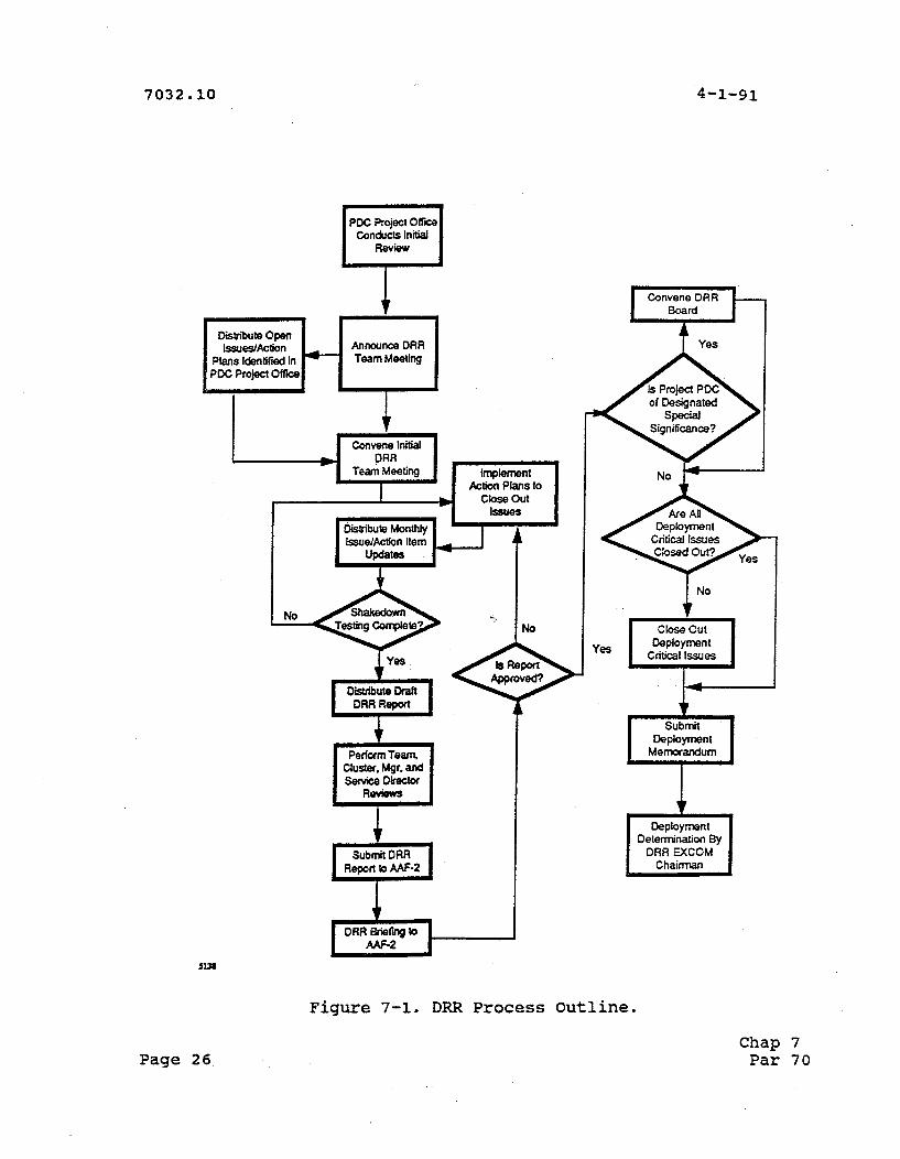
a. General DRR Process. Figure 7-1 outlines the general DRR process by which the PDC Program Manager (ARD-310) will lead an FAA review to ensure that the PDC system is ready to be integrated into the NAS and the FAA is ready to receive, operate, and provide life-cycle support to the equipment when deployed. The DRR process will be accelerated due to the six month implementation period that has been mandated by the FAA Administrator. The two key DRR milestones are as follows:
(1) Initiation of the DRR Process. The project will initiate an internal review of the DRR status upon release of the solicitation. The PDC Program Manager (ARD-310) and the DRR Program Manager (AAF-11) will convene the project DRR teams.
(2) Submission of the DRR Re~ort and Briefinq. After completion of equipment shakedown testing, the PDC Program Manager (ARD-310) will submit a DRR report to the Deputy Associate Administrator for Airway Facilities (AAF-2).
b. DRR Checklist. A detailed DRR checklist will be used by the DRR team to ensure that all significant areas of concern are identified during the review. The PDC DRR team will identify issues/concerns requiring action prior to deployment. All open actions will have a status in the DRR Report to AAF-2. The checklist will address:
(1) NAS system requirements.
(2) Maintenance planning.
(3) Project implementation.
Contract status.
(5) Configuration management.
(6) Facility/site preparedness.
Chap 7 Par 70 Page 25
PDC Project o m Conducts Initial
Disbi te Open
Plans Identifi In PDC Project OK-
DRR Implement
Action Phns to I close Out
J Issues Disbibute Monthly I IssuelActkn Item
Updates L
mrfm Team. cluster. Mgr. and
DRA Briem to kl-
Convene DRR
t Ye.
of Designated
Deployment Critical Issues
Close Out Deployment
Deployment
Determination By DRR EXCOM
C hairrnan
Figure 7-1. DRR Process Outline.
Page 2 6 Chap 7 Par 70

Test program.
(8) Software and firmware integration and maintenance.
(9) NAILS.
Training.
(11) Staffing.
(11) Communications.
(12) Human-Machine interface.
(13) Automated information systems security effectiveness.
(14) General.
c. DRR Executive Committee Meetinqs. The Deputy Associate Administrator for Airway Facilities (AAF-2) will chair the PDC DRR Executive Committee Meetings that will propose the PDC deployment determination to be recommended to the Associate Administrator for Airway Facilities (AAF-1) for approval.
d. PDC DRR Schedule. The PDC DRR Schedule is as follows:
DRR ACTION
Initial DRR Review By Support Contractor DRR Team Announcement Initial DRR Team Meeting Implement Action Plans/Close Open Issues Distribute Action Item Updates Distribute Draft DRR Report Perform Team Review Perform Service Director Review Submit DRR Report to AAF-2 Telcon DRR Briefing to AAF-2 Convene DRR Executive Committee Close Out Deployment Critical Issues Submit Deployment Memorandum Deployment Determination
DATE
09/13/90 10/30/90 11/15/90 11/26/90 Monthly Monthly Monthly 04/02/91 04/04/91 04/04/91 04/11/91 04/18/91 04/10/91
Chap 7 Par 70 Page 27

7032.10
71. SITE PREPARATION.
a. Site Preparation Activities. The PDC system will be installed at 30 airports, which are listed below:
~altimore washington International (BWI) Washington-Dulles (IAD) Washington National (DCA) LaGuardia (LGA) Newark (EWR) John F. Kennedy (JFK) Boston-Logan (BOS) Greater Pittsburgh (PIT) Philadelphia (PHL) Detroit Metropolitan (DTW) ~iami (MIA) Orlando (MCO) ~tlanta-Hartsfield (ATL) Houston Intercontinental (IAH) Memphis (MEM) Charlotte-Douglas (CLT) Raleigh-Durham (RDU) Nashville (BNA) Salt Lake City (SLC) San Francisco (SFO) Seattle-Tacoma (SEA) Honolulu (HNL) Los Angeles (LAX) Las Vegas-McCarran (US) Phoenix-Sky Harbor (PHX) Denver-Stapleton (DEN) Minneapolis-St. Paul (MSP) Chicago-0 Hare (ORD) Dallas-Fort Worth (DFW) St. Louis-Lambert (STL)
Site preparation activities will include the following:
(1) Delivery Order Prevaration. the PDC project office will coordinate PDC requirements and funding arrangements with the affected regional management prior to issuing delivery orders. At a minimum this coordination will address the following:
(a) Equipment to be installed and spares requirements.
(b) Site preparation requirements to include the estimated cost and time to complete.
(c) The installation dates for each site.
Page 28 Chap 7 Par 71
(2) Site Surveys. The PDC contractor will require access to various FAA sites to perform site surveys as required to perform work authorized on the Installation Delivery Orders. The following items will be included in the site survey:
(a) Location of PDC equipment to be installed.
Environmental Control.
(c) Location and availability of power in equipment room and tower cab.
(d) Site Access.
(e) PBX and Centrex impac*.
(f) 4-wire and local loop circuits locations.
(g) Interference and noise at proposed equipment locat ion.
(3) Site Survey Review. At the completion of any site survey, the PDC contractor will identify any significant items that would impact the PDC equipment installation efforts and discuss, with the site manager, procedures the contractor will follow during the installation at the site. A formal site survey report will be prepared for each site and mailed to the respective regions for concurrence.
b. FAA Orsanizations. The respective FAA site manager will be responsible for ensuring that the requisite site preparations are completed on schedule. Regional and local FAA personnel will perform the following site preparation activities:
(1) Provide guidance and assistance to the contractor during site survey activities.
(2) Establish configuration baseline for each site which satisfies floor space, location, and power requirements.
(3) Prepare site plans and procedures necessary to receive and support the installation of the PDC equipment.
(4) Perform site preparation as identified in the site survey report including site engineering and planning, update facility documentation, drill holes through operations floor and walls for cable routing and install AC power and grounding required to support the new equipment.
(5) Support the contractor during installation, e.g., coordinating with contractor installation and integration
Chap 7 Par 71 Page 29

activities and escorting the contractor to and from the installation site.
72. DELIVERY. The majority of the PDC equipment will be stored at ARINC locations until installed at the towers. However, the PDC equipment rack will be delivered directly to the tower, where it will need to be stored, preferably in the PDC equipment location.
73. INSTALLATION PLAN. The ARINC Facilities Engineering organization is primarily responsible for the deployment of the PDC Phase I project. ARINC Field Service is secondarily responsible for this effort. The ARINC Field Services personnel shall be trained on the operation and maintenance of the system before deployment of the systems.
74.-79. RESERVED.
Page 30 Chap 7 Par 71
CHAPTER 8. VERIFICATION
80. HARDWARE VERIFICATION. A series of factory and installation tests will be performed by the PDC contractors.
a. re-~hiwwins Factorv Tests. The ATCT PCs will be verified by ATCT before being shipped from the factory to the ARINC facilities. The standard set of quality assurance tests will be completed.
b. Post-Shiwwins Factorv Tests. The proper operation of all AT&T PCs will be verified by ARINC at the ARINC facilities before installation at the tower. An AT&T person will be present to repair or replace all non-functional equipment.
81. SYSTEM CHECKOUT. The PDC contractor will perform an equipment checkout to demonstrate that the installed equipment meets the functional performance requirements for the basic equipment and any installed options. Checkout will include the following:
a. Testins of the installed eauiwment to verify that integrated hardware and software meet specified functional and operational performance at each site.
b. Verifyins that reauired sumort items such as support manuals are available, technically compatible and in compliance with the contract requirements.
c. Verification of the PDC eauiwment installation at the site by the Onsite Technical Officer Representative (TOR) when checkout has been successfully completed and approved by the site manager. Final acceptance of the installed equipment will be deferred until satisfactory completion of a 30-day trouble-free period of operation.
82. CONTRACTOR INTEGRATION TESTING. ARINC Maintenance Service (AMS) and Field Engineering (FE) personnel shall run through the installation checklist after the systems are installed to determine that all components of the system are operating properly. Integration testing will be performed at each site after installation. This will demonstrate that the PDC equipment meets its functional and system-level performance requirements, has been integrated as specified and can interface and operate with specified external systems/subsystems. These external systems/subsystems will include the line to the FDIO tap and the ADNS connection.
Chap 8 Par 80 Page 31

83. CONTRACTOR ACCEPTANCE INSPECTION (CAI).
a. General. The PDC equipment will be procured using a service type contract. Consequently:
(1) The contractor Acceptance Inspection will be performed by the contractor and the Airway Facility personnel following site training.
(2) FAA Form 256 will be used as the checkoff list.
84. OPERATIONAL TEST & EVALUATIONIINTEGRATION. No FAA integration testing is anticipated for the PDC system due to the lack of an involved automation interface. A PDC system will not be delivered to the Technical Center for Integration Testing during Phase I.
85. OPERATIONAL TEST & EVALUATIONISHAKEDOWN.
a. O~erational Test & Evaluation (OT&E) /Shakedown testing for the PDC system will be conducted as specified by Order 1810.4. This testing will determine the operational effectiveness of the PDC equipment by assessing the integrated readiness of people, procedures, and equipment to assume field operational status. Testing will be accomplished at the first site. ASM-410 will stage the shakedown test for the PDC system. ARINC will provide technical assistance, as required, to isolate and correct any technical and operational deficiencies. The tests will provide FAA personnel with first-hand operational experience on the PDC system and permit them to identify defects or anomalies in the system operation.
(1) In so far as possible, the following will be observed during the shakedown tests: reliability, availability, safety, human factors, and any nonstandard occurrence which might be encountered in operation.
(2) The shakedown testing will test the functional and operational requirements.
(3) Shakedown testing will be conducted by ASM-410 and monitored by the PDC Program Manager (ARD-310), DFW ATCT, ATR- 320, and APMT.
(4) ASM-410 shall be responsible for the development of the OT&E/Shakedown plan and procedures in accordance with Order 1810.4.
b. Field Shakedown ~estinq. Subsequent to a deployment decision, it is anticipated that each system will undergo some field shakedown testing at individual deployment sites. Regional personnel shall conduct field shakedown test & evaluation at each
Page 32 Chap 8 Par 83
field site prior to commissioning. The field shakedown test will be a subset of the first site OTtElshakedown.
86. JOINT ACCEPTANCE INSPECTION (JAI).
a. General. A Joint Acceptance Inspection will be conducted to gain consensus of all responsible FAA organizations that facility modifications are completed in accordance with national criteria, and that the facility is capable of performing its required functions. JAI will be accomplished near the end of each site implementation and prior to the Operational Readiness Demonstration (ORD) .
b. Procedures. The procedures and participants for the JAI are described in Order 6030.45. A JAI will be performed for each installation. ~eficiencies that are found during JAI and are a result of the PDC contractor will be assigned as action items to the Program Office for resolution.
c. Reauired Preparations. The following items must be accomplished prior to performing the JAI for a site.
(1) Inspection and inventory of the equipment delivered to the site.
(2) Completion of site installation and specific site installation testing.
(3) Completion of shakedown testing.
(4) Correction of all identified discrepancies or uncompleted items from FAA OT&E/Shakedown testing.
(5) Completion/review of JAI report forms (FAA Forms 6030-18 through 6030-25).
(6) Notification of convening Joint Acceptance Board.
(7) Completion of CAI.
d. Joint Acceptance Board (JAB). A JAB will be convened to formally conduct the JAI for each installation. The JAB consists of representatives of the Airway Facilities sector, Air Traffic, ARD-300 Program Office responsible for project implementation, and others, as appropriate. The composition and responsibilities of the JAB are described in Order 6030.45.
e. JAI Re~ort. FAA Forms 6030-18 through 6030-25 will be used to document all the findings of the board. The Chairman of the JAB is responsible for the JAI Report.
Chap 8 Par 85 Page 33
87. CONFIGURATION MANAGEMENT (CM). The PDC is a commercial system for which configuration will be controlled and maintained both during the acquisition and implementation of PDC phase 1.
a. Acauisition Phase Confiauration Manasement. During the acquisition phase the PDC configuration will be controlled and maintained by the contractor as required by the terms of the contract. The contractor is required to establish, implement, and maintain a CM program in accordance with FAA-STD-021, Configuration Management, and documented in a Configuration Management Plan. The contractor will establish a Configuration Change Board (CCB) to establish baselines and support baseline management. The contractor will submit Engineering Change Proposals (ECP) to the Contracting Officer for proposed changes to configuration items. Configuration items are to be systematically identified and marked; the contractor will prepare Configuration Item Development Records for each item. Configuration Status Accounting (CSA) Reports will be provided to the FAA. The contractor will develop a Configuration Audit Plan and conduct configuration audits on all delivered hardware, software, and documentation. ARD-310 is responsible for monitoring the contractor's CM program during the life of the contract.
(1) The ARD Confiauration Control Board (CCB) controls the establishment of and changes to the hardware and software baselines during the acquisition phase. For PDC matters, the CCB will include members from Air Traffic, Maintenance Operations, Contracts, System Engineering, Configuration Management, and the SEI contractor. The CCB is responsible for ensuring the functional, performance and interface requirements allocated to the PDC hardware and software subsystems are reflected in the baseline documentation, and is responsible for controlling any changes to that documentation. The CCB retains this CM responsibility until the last ORD.
( 2 ) As a prerequisite to establishing the Product Baseline, the contractor is required to conduct the ~unctional configuration Audit (FCA) and Physical configuration Audit (PCA) with FAA participation.
(3) Upon successful com~letion of the FCA and PCA, ARD-310 will initiate a case file for the PDC Product Baseline in accordance with FAA Order 1800.8E, National Airspace System configuration Management, for approval by the CCB.
b. Transition of Hardwarelsoftware Confisuration Manasement. The CM responsibility associated with PDC software will transition from ARD to ASM-400 after the last ORD. Subsequently, approval authority of all hardware NAS Change Proposal (NCP) activity will transition from the ARD CCB to the Maintenance Engineering (ME) CCB and all software NCP activity to
Page 34 Chap 8 Par 87

the Air Traffic (AT) CCB. A hand-off package for PDC will be prepared by ARD-310 consisting of all hardware, technical and provisioning documentation, all software media, and all supporting documentation and site installation documentation.
c. O~erational Sumort Phase Confiauration Manasement. During the operational support phase, and for the entire life- cycle of the implemented PDC hardware and software, CM functions will consist of maintenance and change control management to ensure the integrity of the approved Product Baseline.
88.-89. RESERVED.
Chap 8 Par 87 Page 35

CHAPTER 9. INTEGRATED LOGISTICS SUPPORT
90. MAINTENANCE PLANNING.
a. General. The primary source for maintenance support for the life of the PDC equipment will be the PDC contractor. The Technical Standards Branch (ASM-120) is the primary interface point for the contractor maintenance system support. There are two basic types of maintenance that will be provided by the PDC contractor: corrective maintenance, which includes on call, and preventive maintenance.
b. Contractor Corrective Maintenance. ARINC will provide a total maintenance support package for the PDC equipment. Maintenance will be provided by the contractor onsite. The contractor will provide the following maintenance support:
(1) Onsite Maintenance. ARINC Operations/Annapolis will be the point of contact for PDC System Troubles reported by FAA Tower personnel. A toll free telephone number is provided to the FAA for this purpose. ARINC Operations/Annapolis will also be the central point for detection of communications and facility alarms.
(2) Contract Period. The initial period of the ARINC PDC contract is 5 years. There are 5 one-year extension options available for the PDC contractor to perform onsite corrective maintenance. The FAA OATS contract is for 8 years of AT&T computer maintenance. The first two years will be funded for each system by the program office, the remaining years will be funded by the Systems Maintenance Service, ASM-1.
c. Contractor Preventive Maintenance. Routine test and adjustments for major assemblies will be scheduled as recommended by the manufacturer and ARINC1s operating experience. The preventative maintenance will be the responsibility of ARINC.
91. TRAINING. Training will be performed at each site prior to use of the system. Three different courses will be taught: System ~dministration, Clearance Delivery Controller, and Airway Facilities support.
a. System Administration. Initial training consists of a four hour formal training session for System Administrator(s). Personnel will receive a 30 minute supervised hands-on system introduction. A videotape will be available for employees trained after the initial training sessions.
b. Clearance Delivery Controller. Initial training consists of a one half to one hour formal training session for
Page 36 Chap 9 Par 90
Clearance Delivery Controller trainers. Personnel will receive a 30 minute supervised hands-on system introduction. Employees trained after the initial training sessions will be provided a videotape.
c. Airwav Facilities. Initial training consists of a one half to one hour formal training session for Airway Facilities personnel. Personnel will receive a 30 minute supervised hands- on system introduction. Employees trained after the initial training sessions will be provided a videotape.
d. On the Job Training. This will be the primary training vehicle for tower personnel. Due to the simplicity of the user interface, more intensive training is unnecessary. New employees will receive the same amount of training as those present for the initial training sessions and will be able to become proficient on the equipment in a very short time. Following training, the first 30 minutes of system operation will be supervised, to insure that the employee has grasped the system concepts. Subsequently, personnel can proceed without supervision.
e. -User Manual. A user manual will be provided during initial instruction and will be available to tower personnel for reference. The user manual will describe, in detail, the functioning of the system and the measures to take in cases of exceptions. Airports with unique procedures will receive the basic user manual with an addendum specifically addressing their individual requirements.
92. SUPPORT TOOLS AND TEST EOUIPMENT. Special tools, test/support equipment and/or interface devices required to support the PDC system will be held to a minimum. The PDC contractor will identify, in a list of recommended tools and equipment, interface devices and connectors needed to maintain the PDC system.
93. SUPPLY SUPPORT. The present support concept of complete contractor maintenance and support of workstation hardware and software negates the requirement for site and depot level sparing of those items. This will also negate the need for a formal provisioning conference for PDC.
94. VENDOR DATA AND TECHNICAL MANUALS. The PDC contractor will deliver manuals listed in section 56, Planning and Reports, as well as those listed below:
a. System/Segment Specification (SSS).
b. Software User's Manual.
c. Computer System Operator's Manual.
Chap 9 Par 91 Page 37

d. Test Procedures.
e. Software Product Specification.
f. Software Test Procedures.
g. Software Detailed Design Document.
h. Software Top Level Design Document.
95. EOUIPMENT REMOVAL. The three demonstration systems will need to be removed after the new systems are operational. The equipment will be returned to MITRE and ARINC.
96. FACILITIES. PDC equipment will be configured to fit within existing space allocated at the FAA facilities. No special responsibilities have been assigned to the Government for designing, developing, or acquiring support facilities.
97. EOUIPMENT ACCOUNTABILITY. Accountability and recording of equipment will be accomplished in accordance with Order 4650.21B, Management In-Use Personal Property. Property that is recorded in the Uniform Accounting Systems will be accomplished in accordance with Order 2700.32, Uniform Accounting System Operations Manual.
98.-99. RESERVED.
Page 38 Chap 9 Par 94