Embed Size (px)
Citation preview
USER’S HANDBOOK
COSPAS-SARSAT TEST BENCHES
STB-06-A & STB-06-LA
Issued by
ELTA
F6614
14 Place Marcel Dassault
31702 BLAGNAC
France
www.elta.fr
ORGANISM ASSIGNATION
LABEL LOCATION
Documentation P/N: 02E65745 Rev. G
Initial issue: Jan 31/03 Title Page Mar. 08/12
USER’S HANDBOOK
LIST OF UPDATES
INSERTION INSERTION UPDATE
No. ISSUE
DATE BY
UPDATE No.
ISSUE DATE BY
Creation
Typing correction & clarification
New software release
New Software release
V1.2.6.0 and integration
of the CodADT
tool
New software
V1.2.7.0
New PC Computer
New PC Computer
New Software Release V1.2.8.0
A Prelim.
A
B
C
D
E
F
G
Jan./Feb. 03
Nov. 03
Nov. 03
July 06
Oct. 07
Nov. 07
Jun. 11
Mar. 12
ELTA
ELTA
ELTA
ELTA
ELTA
ELTA
ELTA
ELTA
Page 1
Mar. 08/12

USER’S HANDBOOK
PAGE INTENTIONALLY LEFT BLANK
Page 2
BLANK
USER’S HANDBOOK
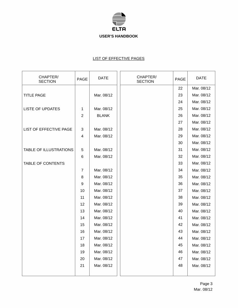
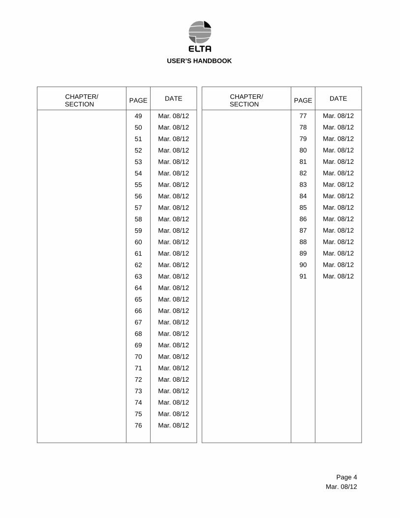
LIST OF EFFECTIVE PAGES
CHAPTER/ SECTION
PAGE DATE CHAPTER/ SECTION
PAGE DATE
TITLE PAGE
LISTE OF UPDATES
LIST OF EFFECTIVE PAGE
TABLE OF ILLUSTRATIONS
TABLE OF CONTENTS
1
2
3
4
5
6
7
8
9
10
11
12
13
14
15
16
17
18
19
20
21
Mar. 08/12
Mar. 08/12
BLANK
Mar. 08/12
Mar. 08/12
Mar. 08/12
Mar. 08/12
Mar. 08/12
Mar. 08/12
Mar. 08/12
Mar. 08/12
Mar. 08/12
Mar. 08/12
Mar. 08/12
Mar. 08/12
Mar. 08/12
Mar. 08/12
Mar. 08/12
Mar. 08/12
Mar. 08/12
Mar. 08/12
Mar. 08/12
22
23
24
25
26
27
28
29
30
31
32
33
34
35
36
37
38
39
40
41
42
43
44
45
46
47
48
Mar. 08/12
Mar. 08/12
Mar. 08/12
Mar. 08/12
Mar. 08/12
Mar. 08/12
Mar. 08/12
Mar. 08/12
Mar. 08/12
Mar. 08/12
Mar. 08/12
Mar. 08/12
Mar. 08/12
Mar. 08/12
Mar. 08/12
Mar. 08/12
Mar. 08/12
Mar. 08/12
Mar. 08/12
Mar. 08/12
Mar. 08/12
Mar. 08/12
Mar. 08/12
Mar. 08/12
Mar. 08/12
Mar. 08/12
Mar. 08/12
Page 3
Mar. 08/12
USER’S HANDBOOK
CHAPTER/ SECTION
PAGE DATE CHAPTER/ SECTION
PAGE DATE
49
50
51
52
53
54
55
56
57
58
59
60
61
62
63
64
65
66
67
68
69
70
71
72
73
74
75
76
Mar. 08/12
Mar. 08/12
Mar. 08/12
Mar. 08/12
Mar. 08/12
Mar. 08/12
Mar. 08/12
Mar. 08/12
Mar. 08/12
Mar. 08/12
Mar. 08/12
Mar. 08/12
Mar. 08/12
Mar. 08/12
Mar. 08/12
Mar. 08/12
Mar. 08/12
Mar. 08/12
Mar. 08/12
Mar. 08/12
Mar. 08/12
Mar. 08/12
Mar. 08/12
Mar. 08/12
Mar. 08/12
Mar. 08/12
Mar. 08/12
Mar. 08/12
77
78
79
80
81
82
83
84
85
86
87
88
89
90
91
Mar. 08/12
Mar. 08/12
Mar. 08/12
Mar. 08/12
Mar. 08/12
Mar. 08/12
Mar. 08/12
Mar. 08/12
Mar. 08/12
Mar. 08/12
Mar. 08/12
Mar. 08/12
Mar. 08/12
Mar. 08/12
Mar. 08/12
Page 4
Mar. 08/12
USER’S HANDBOOK
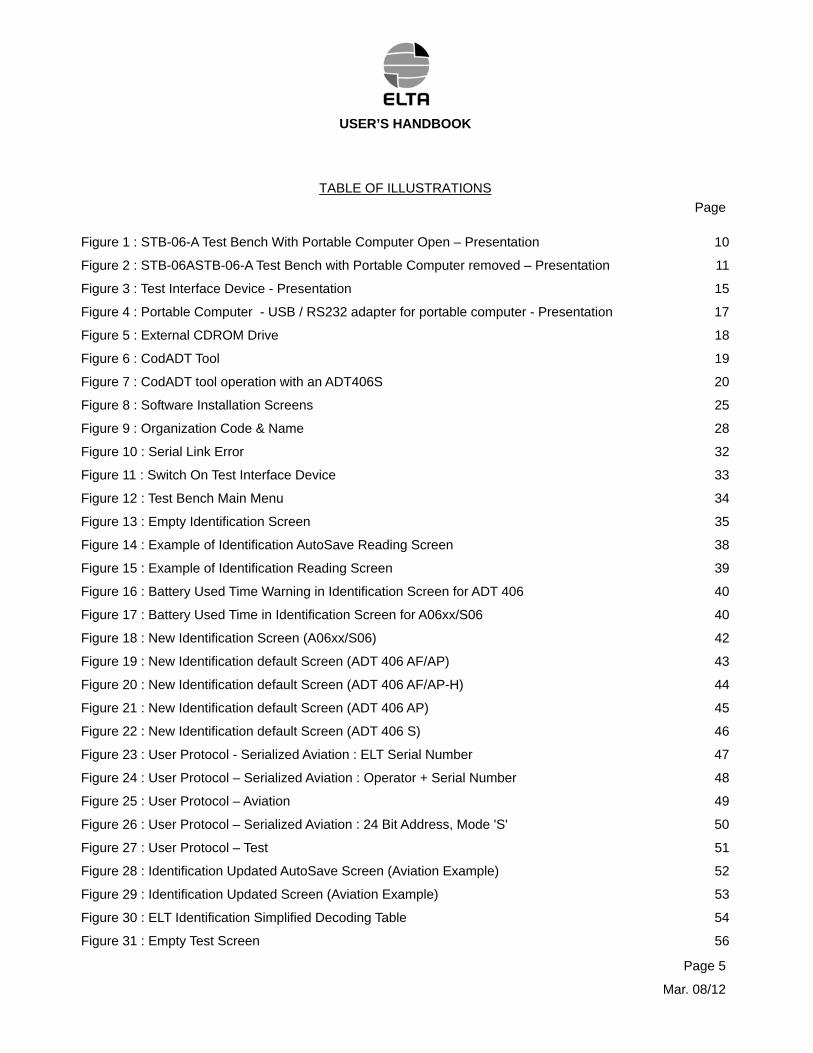
TABLE OF ILLUSTRATIONS
Page
Figure 1 : STB-06-A Test Bench With Portable Computer Open – Presentation 10
Figure 2 : STB-06ASTB-06-A Test Bench with Portable Computer removed – Presentation 11
Figure 3 : Test Interface Device - Presentation 15
Figure 4 : Portable Computer - USB / RS232 adapter for portable computer - Presentation 17
Figure 5 : External CDROM Drive 18
Figure 6 : CodADT Tool 19
Figure 7 : CodADT tool operation with an ADT406S 20
Figure 8 : Software Installation Screens 25
Figure 9 : Organization Code & Name 28
Figure 10 : Serial Link Error 32
Figure 11 : Switch On Test Interface Device 33
Figure 12 : Test Bench Main Menu 34
Figure 13 : Empty Identification Screen 35
Figure 14 : Example of Identification AutoSave Reading Screen 38
Figure 15 : Example of Identification Reading Screen 39
Figure 16 : Battery Used Time Warning in Identification Screen for ADT 406 40
Figure 17 : Battery Used Time in Identification Screen for A06xx/S06 40
Figure 18 : New Identification Screen (A06xx/S06) 42
Figure 19 : New Identification default Screen (ADT 406 AF/AP) 43
Figure 20 : New Identification default Screen (ADT 406 AF/AP-H) 44
Figure 21 : New Identification default Screen (ADT 406 AP) 45
Figure 22 : New Identification default Screen (ADT 406 S) 46
Figure 23 : User Protocol - Serialized Aviation : ELT Serial Number 47
Figure 24 : User Protocol – Serialized Aviation : Operator + Serial Number 48
Figure 25 : User Protocol – Aviation 49
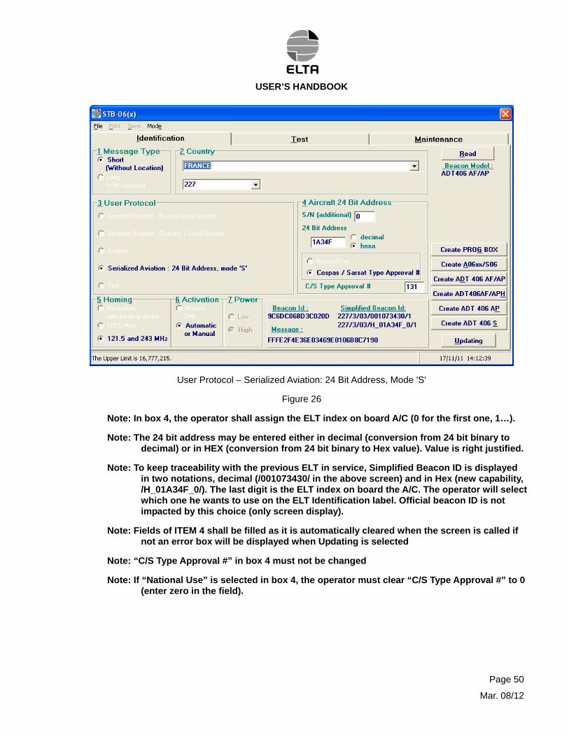
Figure 26 : User Protocol – Serialized Aviation : 24 Bit Address, Mode 'S' 50
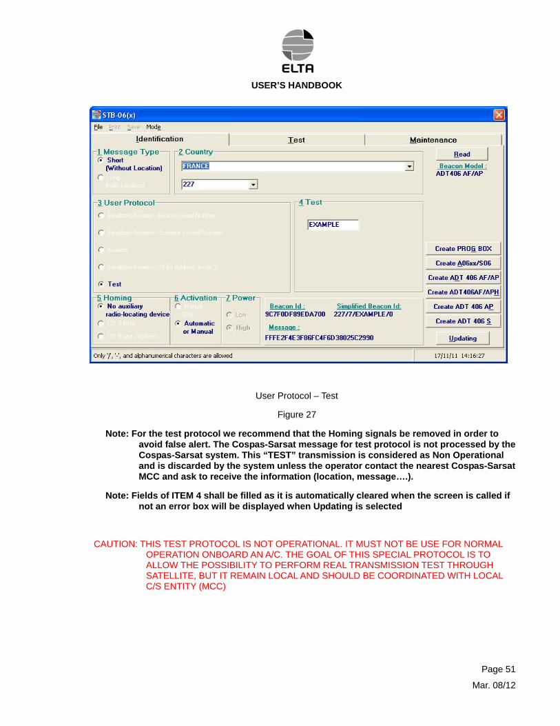
Figure 27 : User Protocol – Test 51
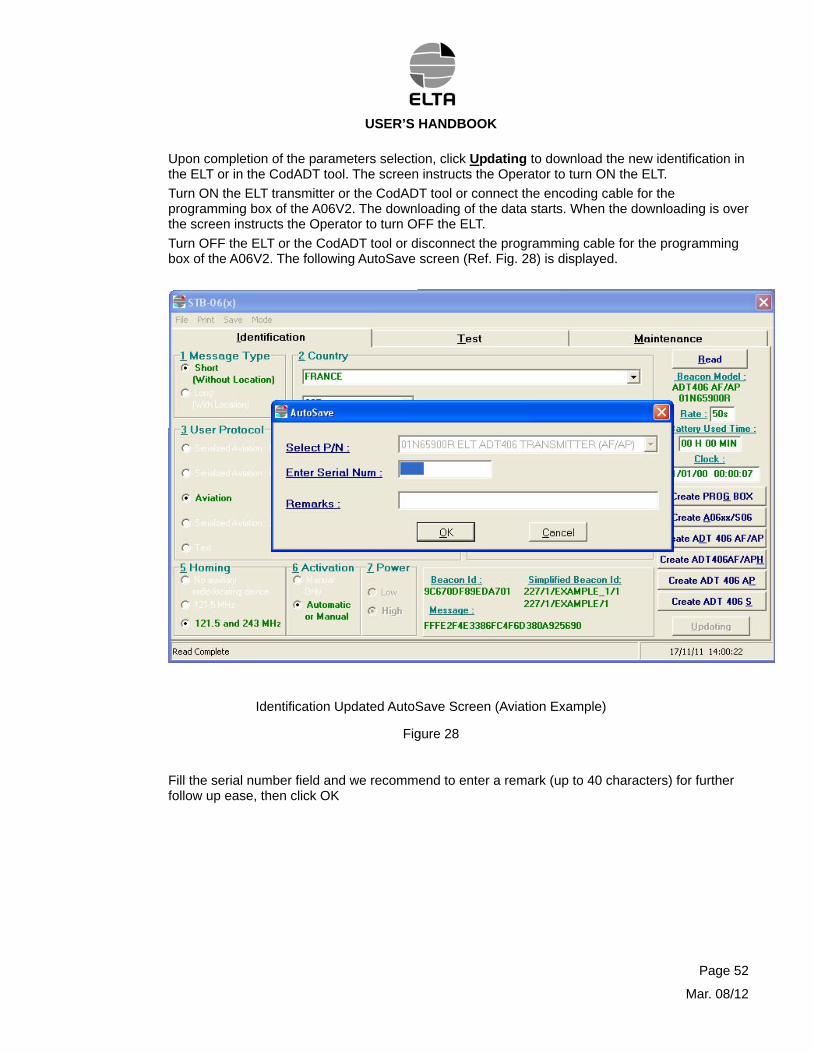
Figure 28 : Identification Updated AutoSave Screen (Aviation Example) 52
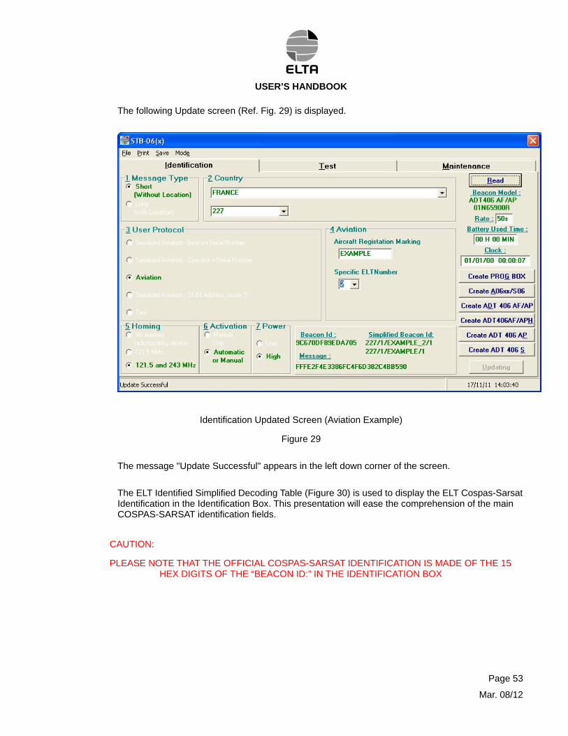
Figure 29 : Identification Updated Screen (Aviation Example) 53
Figure 30 : ELT Identification Simplified Decoding Table 54
Figure 31 : Empty Test Screen 56
Page 5
Mar. 08/12
USER’S HANDBOOK
Page 6
Mar. 08/12
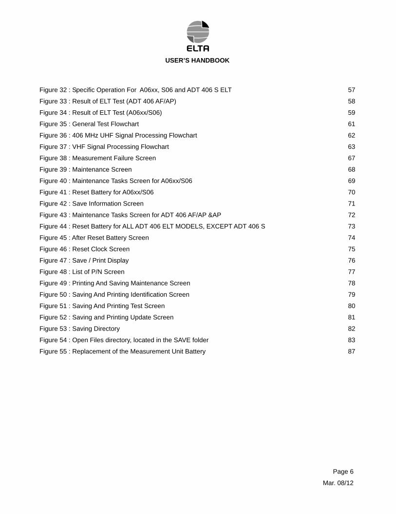
Figure 32 : Specific Operation For A06xx, S06 and ADT 406 S ELT 57
Figure 33 : Result of ELT Test (ADT 406 AF/AP) 58
Figure 34 : Result of ELT Test (A06xx/S06) 59
Figure 35 : General Test Flowchart 61
Figure 36 : 406 MHz UHF Signal Processing Flowchart 62
Figure 37 : VHF Signal Processing Flowchart 63
Figure 38 : Measurement Failure Screen 67
Figure 39 : Maintenance Screen 68
Figure 40 : Maintenance Tasks Screen for A06xx/S06 69
Figure 41 : Reset Battery for A06xx/S06 70
Figure 42 : Save Information Screen 71
Figure 43 : Maintenance Tasks Screen for ADT 406 AF/AP &AP 72
Figure 44 : Reset Battery for ALL ADT 406 ELT MODELS, EXCEPT ADT 406 S 73
Figure 45 : After Reset Battery Screen 74
Figure 46 : Reset Clock Screen 75
Figure 47 : Save / Print Display 76
Figure 48 : List of P/N Screen 77
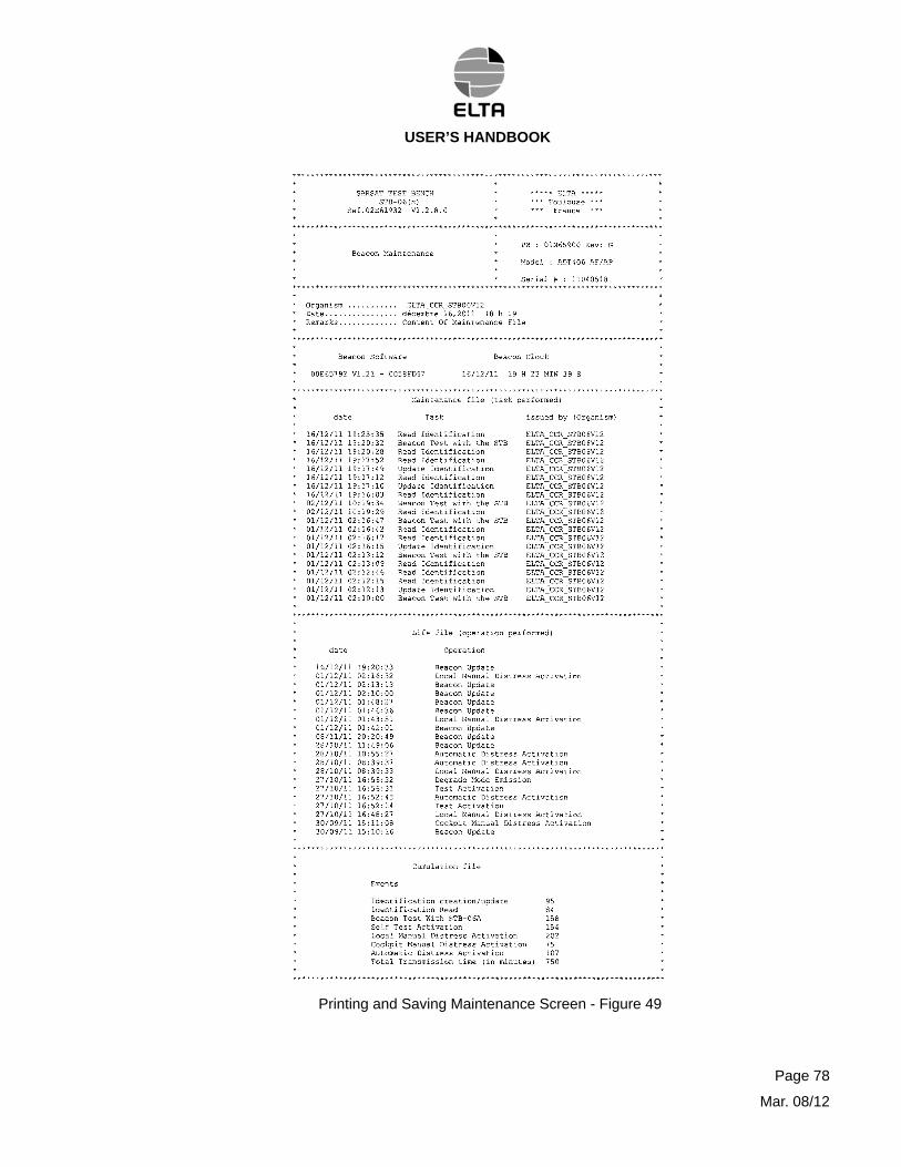
Figure 49 : Printing And Saving Maintenance Screen 78
Figure 50 : Saving And Printing Identification Screen 79
Figure 51 : Saving And Printing Test Screen 80
Figure 52 : Saving and Printing Update Screen 81
Figure 53 : Saving Directory 82
Figure 54 : Open Files directory, located in the SAVE folder 83
Figure 55 : Replacement of the Measurement Unit Battery 87
USER’S HANDBOOK
TABLE OF CONTENTS
PAGE
LIST OF UPDATES 1
LIST OF EFFECTIVE PAGES 3
TABLE OF ILLUSTRATIONS 5
TABLE OF CONTENTS 7
1. INTRODUCTION 8
2. GENERAL 8
A. Purpose of the test bench 8
B. Software Improvement from the initial version 8
C. List of ELT model addressed by STB-06 test bench 9
D. General characteristics 9
3. DESCRIPTION 12
A. General description (Ref. Fig. 1 & 2) 12
B. Detailed description 14
4. OPERATION 22
A. External Power Supply operation 22
B. Returning to service after long-duration storage 22
C. Putting into service 23
D. Software installation (STB-06-LA, laboratory version, or STB-06-A recovery) 25
E. Functional test of ELT 31
5. MAINTENANCE 84
A. Calibration 84
B. Spare parts list 84
C. Fault locating 85
6. REPLACEMENT OF THE BATTERY 85
A. Computer 85
B. CodADT tool 86
C. Test Interface Device (Ref. Fig 55): 86
7. LIST OF COUNTRIES AND THE ASSOCIATED COUNTRY CODES IN ALPHABETICAL ORDER 87
Page 7
Mar. 08/12
USER’S HANDBOOK
1. INTRODUCTION
This document describes the STB-06-(x) test bench.
The test bench exists in two versions:
- a complete portable and autonomous test bench powered by internal batteries, model STB-06-A, P/N 02N65740,
- a laboratory test bench, model STB-06-LA,P/N 02N65739..
Operations and performances are identical between the two versions.
The differences are the housing metallic transport case and utilization of a portable computer for STB-06-A.
STB-06-LA requires use of a computer that is supplied by the customer.
2. GENERAL
A. Purpose of the test bench
The STB-06-A test bench can be powered from the shop power supply or using its own internal battery in portable configuration. It can be used in workshop or onboard A/C.
The STB-06-LA is limited to work shop application
They are used to:
Check the Radio Frequency (RF) performances of the different ELT’ transmitters
ELT or Programming Box Cospas-Sarsat identification management.
They contain everything required for programming and testing the performance of ELT’ distress beacon.
B. Software Improvement from the initial version
The new release version 1.2.8.0. Incorporates the following evolutions of the test bench software:
Upgrade to process the new Cospas-Sarsat “User Aviation Protocol” (management of “specific ELR Number”,
Addition of “ADT 406 AF/AP – H” ELT new model dedicated to helicopters application (PN: 01N65901),
Improvement of the Compatibility for Windows 7 (or Vista),
New software location on computer main hard disk under "…\Program Files\ELTA\STB-06-V1.2.8.0" new directory (allows operation of several test bench variants on the same computer).
Page 8
Mar. 08/12
USER’S HANDBOOK
C. List of ELT model addressed by STB-06 test bench
ELT model ELT Type ELT P/N Rev. (Amendment)
ADT 406 AF/AP Automatic Fixed 01N65900 A to K
ADT 406² AF/AP Automatic Fixed 01N65900 L and above
ADT 406² AF/AP-H Automatic Fixed 01N65901 A and above
ADT 406 AP Automatic Portable 01N65910 A and above
ADT 406 S Survival 01N65920 A and above
A06 Automatic Portable 9260065 A and above
A06V2 Automatic Portable 95N6088 A and above
Prog.Box To be use with A06V2 95N6089 A and above
A06T Automatic Portable 94N6576 A and above
A06GE Automatic Portable 93N6205 A and above
A06M Automatic Fixed 02N62322 A and above
S06 Survival 94N6576 A and above
D. General characteristics
(1)Environment
Operating temperature with the case open : 5°C to +35°C.
Storage temperature with the case closed : 0°C to +55°C.
Humidity without condensation : 20% to 80%
(2)Transport case closed (STB-06-A only)
When the transport case is closed, the test bench components are protected against:
- Dust. All the test bench components are protected against harmful deposits,
- Impacts (0.225 joule). The case can withstand a weight of 150 grams dropped from a height 15 cm.
The case is designed to withstand vibrations with a frequency of 5 to 150 Hz and an acceleration of 1G on all 3 axes.
(3)Transport case open
When the transport case is open, the test bench components are not protected or immobilized.
It is also the case for the STB-06-LA version.
Page 9
Mar. 08/12
USER’S HANDBOOK
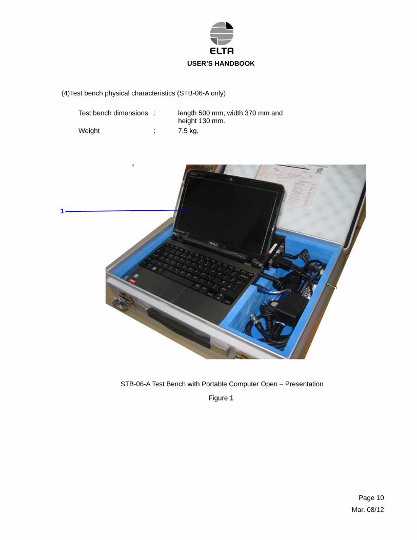
(4)Test bench physical characteristics (STB-06-A only)
Test bench dimensions : length 500 mm, width 370 mm and height 130 mm.
Weight : 7.5 kg.
1
STB-06-A Test Bench with Portable Computer Open – Presentation
Figure 1
Page 10
Mar. 08/12
USER’S HANDBOOK
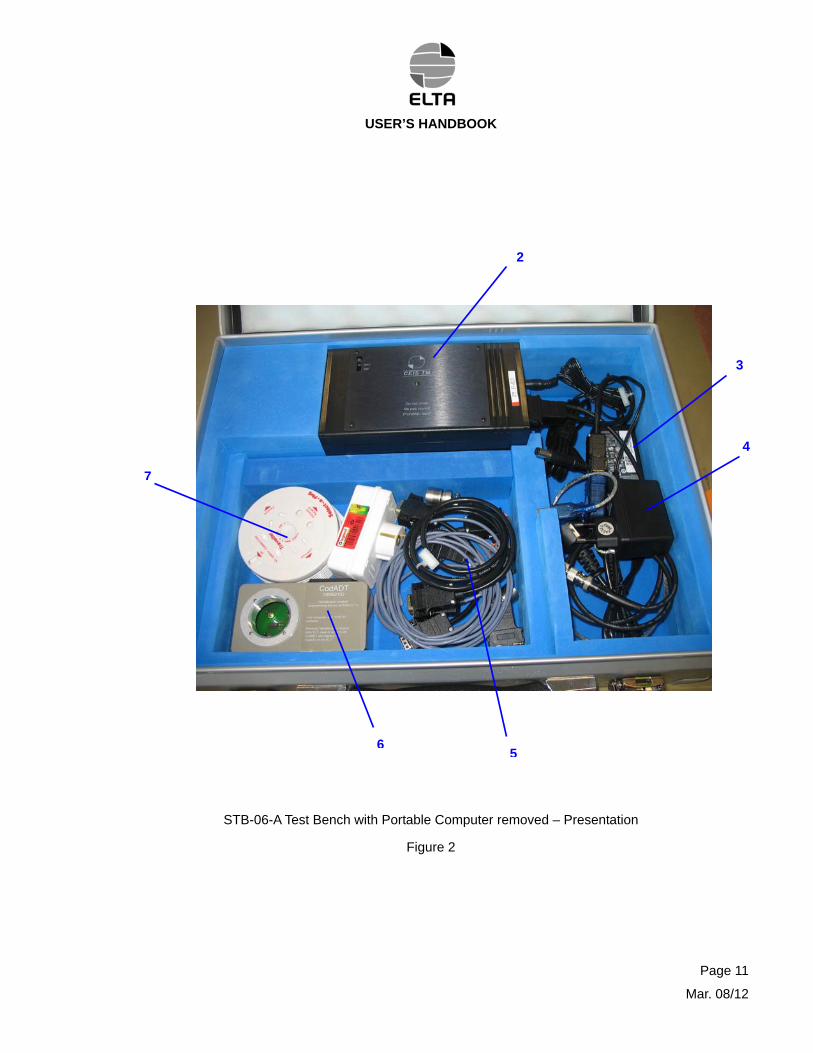
2
4
7
3
65
STB-06-A Test Bench with Portable Computer removed – Presentation
Figure 2
Page 11
Mar. 08/12
USER’S HANDBOOK
Page 12
Mar. 08/12
3. DESCRIPTION
A. General description (Ref. Fig. 1 & 2)
(1) STB-06-A
The STB-06-A test bench portable version essentially consists of the following components:
- Portable Computer (Fig1 [1]),
- Test Interface Device (Fig2 [2]),
- Power Supply Adapter (Fig2 [3] & [4]), one for the computer, the other for the “Test Interface Device”
- Connection Cables (Fig2 [5]),
- CodADT tool for programming “Identification modules” of ADT 406 ELT’ (Fig2 [6])
- Plug Adapter (Fig2 [7]) adapts power supply connectors to the plug configuration around the world,
The test bench components are placed in the housings made of dedicated foam.
Connection cables include:
- Programming Cable for ELT model A06/A06V1/A06T/S06: P/N 93N6222,
- Programming Cable for the Programming Box of the ELT model A06V2: P/N 96N9028,
- Extension Cable for the ELT model A06V2: P/N 96N9029 (extends the cable P/N 96N9028),
- Programming Cable for ELT model ADT 406 (x): P/N 02N65746,
- Coaxial Cable for any ELT model: P/N 94N6460,
- 5 meters serial link extension cable: P/N 02N66199,
- RS232/USB adapter for portable computer : P/N 28946,
- RS232 cable between USB adapter and Test Interface Device : P/N 94N6493
Note: Recovery software (ELTA & computer) on CD ROM is supplied separately (not included in the transport suitcase) for recovery in case of ELTA test bench software damage.
USER’S HANDBOOK
(2) STB-06-LA (Ref. Fig. 2)
The STB-06-LA test bench, laboratory version use the same parts and is composed of:
- Computer, not supplied by ELTA (not illustrated),
- Test Interface Device (2),
- External Power Supply Adapter (4 only), for the “Test Interface Device”.
- Connection Cables (5),
- CodADT tool (6) for programming “Identification modules” of ADT 406 ELT’.
- Plug Adapter (7) adapts power supply connectors to the plug configuration around the world,
Connection cables include:
- Programming Cable for ELT model A06/A06V1/A06T/S06: P/N 93N6222,
- Programming Cable for the Programming Box of the ELT model A06V2: P/N 96N9028,
- Extension Cable for the ELT model A06V2: P/N 96N9029 (extends the cable P/N 96N9028),
- Programming Cable for ELT model ADT 406 (x): P/N 02N65746,
- Coaxial Cable for any ELT model: P/N 94N6460,
- RS 232 serial link for computer connection: P/N 95N6072.
Page 13
Mar. 08/12
USER’S HANDBOOK
B. Detailed description
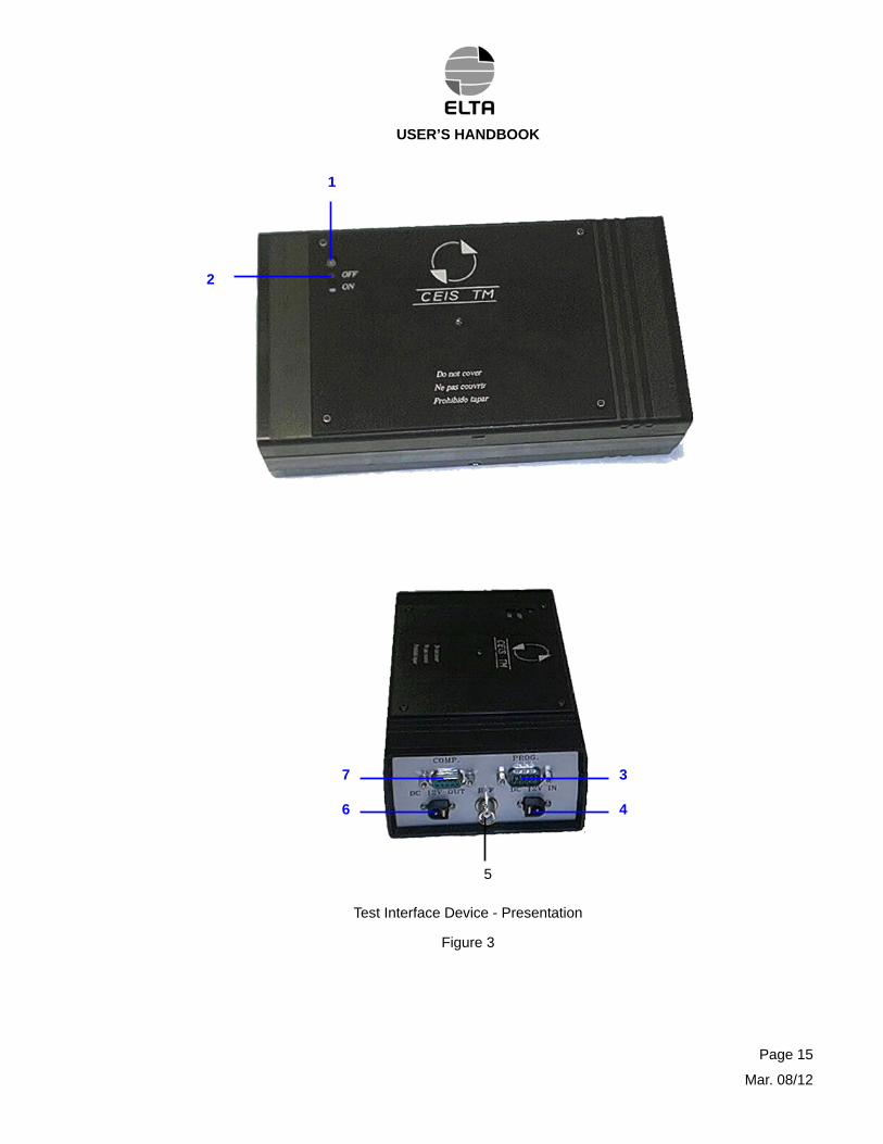
(1)Test Interface Device
The Test Interface Device essentially consists of a measuring board and a battery integrated in a non-waterproof box. The battery provides a typical autonomy of 2 hours after a complete recharge process - Batteries needs to be recharged for at least 5 hours.
The Test Interface Device has a phase demodulator for UHF measurements and an audio demodulator for the VHF measurements. It measures the radio-frequency (RF) characteristics for three frequencies: 406 MHz, 243 MHz and 121.5 MHz.
The following components are located on the top of the Test Interface Device (Ref. Fig. 3) :
- Three-color indicator light (1) :
Green indicates that the Test Interface Device is in operation (ON position),
Red indicates that the Test Interface Device's internal battery is being recharged. The red light goes out automatically when battery-charging process has been completed,
Flashing red indicates a low battery state. Battery requires recharging. The Test Interface Device's and probably the computer's battery must then be recharged.
When both colors (green and red) are on, the indicator light is orange so:
Permanent orange indicates that the Test Interface Device is “ON” and battery is recharging,
Flashing orange indicated that the device is “ON” and battery needs to be recharged soon.
- The Test Interface Device's ON/OFF slide switch (2).
Note: Avoid to cover the Test Interface Device with paper or any other thing, allowing normal cooling during battery charging or operation (heat sink).
Connectors are installed on one face (right) of the Test Interface Device. The following connections are provided:
- PROG connector (3) to which the optional programming cable is connected,
- DC 12V IN connector (4) to which the external power supply adapter is connected (Fig. 2 item 5),
- RF connector (5) which receives the RF signals from the ELT,
- DC 12V OUT connector (6), Not Used anymore must remain unconnected,
- COMP connector (7) provides the RS232 link with the portable computer or basic computer in the laboratory version (STB-06-LA).
Page 14
Mar. 08/12
USER’S HANDBOOK
Page 15
Mar. 08/12
7
6 4
3
2
1
5
Test Interface Device - Presentation
Figure 3
USER’S HANDBOOK
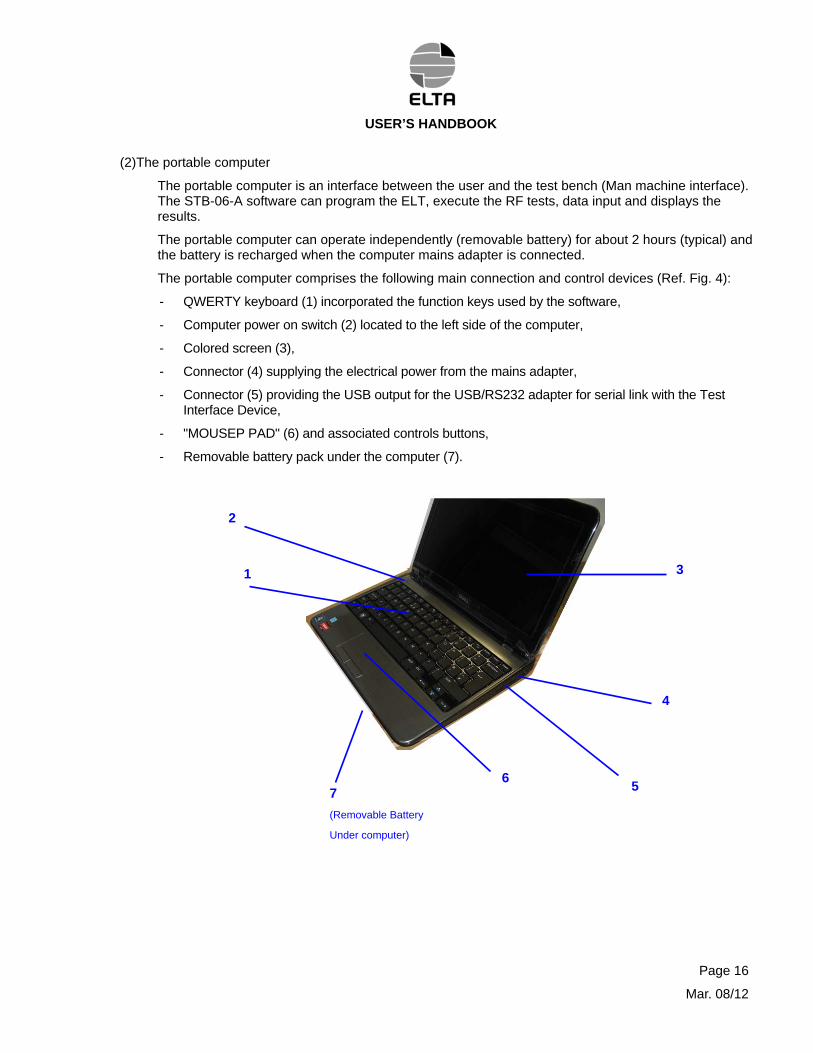
(2)The portable computer
The portable computer is an interface between the user and the test bench (Man machine interface). The STB-06-A software can program the ELT, execute the RF tests, data input and displays the results.
The portable computer can operate independently (removable battery) for about 2 hours (typical) and the battery is recharged when the computer mains adapter is connected.
The portable computer comprises the following main connection and control devices (Ref. Fig. 4):
- QWERTY keyboard (1) incorporated the function keys used by the software,
- Computer power on switch (2) located to the left side of the computer,
- Colored screen (3),
- Connector (4) supplying the electrical power from the mains adapter,
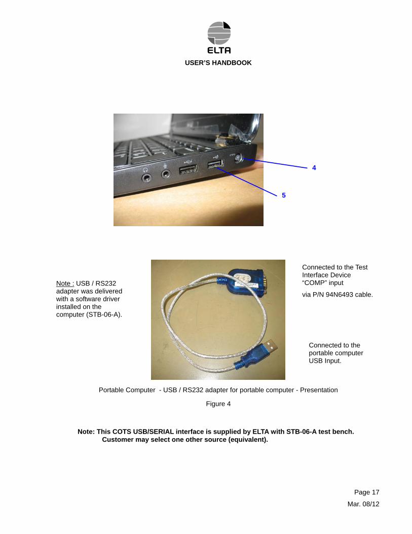
- Connector (5) providing the USB output for the USB/RS232 adapter for serial link with the Test Interface Device,
- "MOUSEP PAD" (6) and associated controls buttons,
- Removable battery pack under the computer (7).
2
1 3
7
(Removable Battery
Under computer)
5 6
4
Page 16
Mar. 08/12
USER’S HANDBOOK
5
4
Connected to the Test Interface Device “COMP” input
via P/N 94N6493 cable.
Note : USB / RS232 adapter was delivered with a software driver installed on the computer (STB-06-A).
Connected to the portable computer USB Input.
Portable Computer - USB / RS232 adapter for portable computer - Presentation
Figure 4
Note: This COTS USB/SERIAL interface is supplied by ELTA with STB-06-A test bench. Customer may select one other source (equivalent).
Page 17
Mar. 08/12
USER’S HANDBOOK
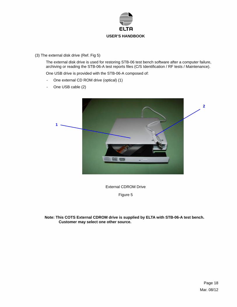
(3) The external disk drive (Ref. Fig 5)
The external disk drive is used for restoring STB-06 test bench software after a computer failure, archiving or reading the STB-06-A test reports files (C/S Identification / RF tests / Maintenance).
One USB drive is provided with the STB-06-A composed of:
- One external CD ROM drive (optical) (1)
- One USB cable (2)
2
1
External CDROM Drive
Figure 5
Note: This COTS External CDROM drive is supplied by ELTA with STB-06-A test bench. Customer may select one other source.
Page 18
Mar. 08/12
USER’S HANDBOOK
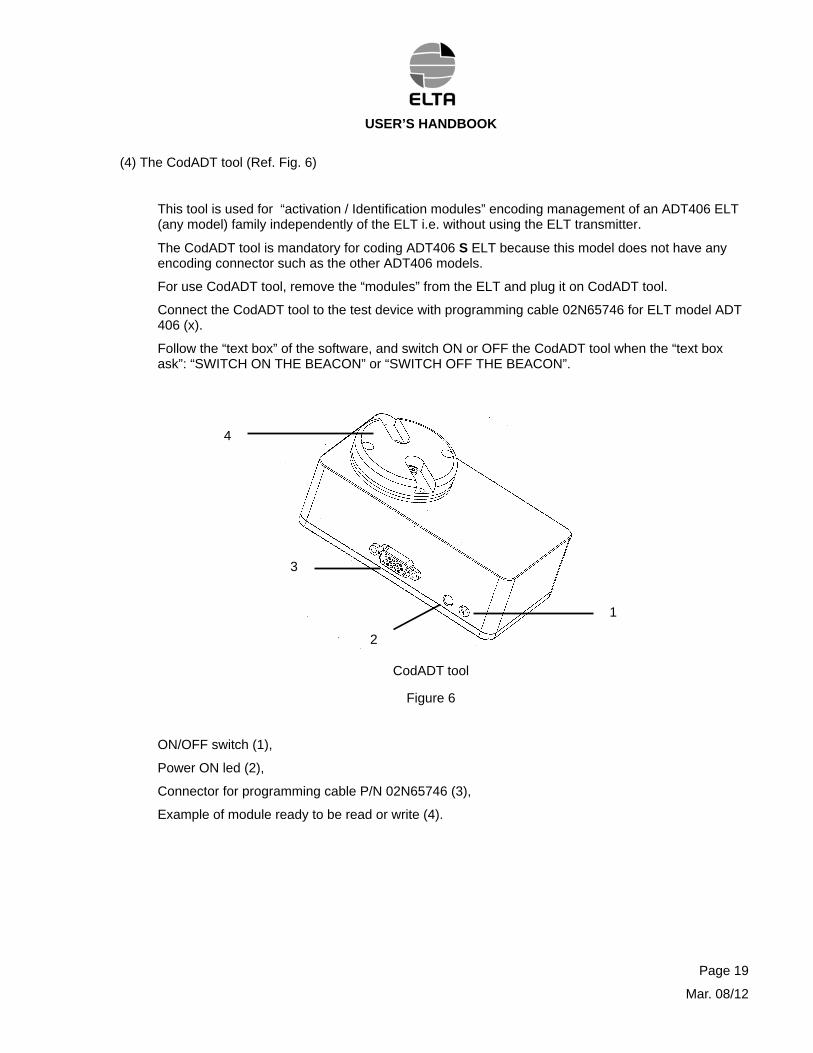
(4) The CodADT tool (Ref. Fig. 6)
This tool is used for “activation / Identification modules” encoding management of an ADT406 ELT (any model) family independently of the ELT i.e. without using the ELT transmitter.
The CodADT tool is mandatory for coding ADT406 S ELT because this model does not have any encoding connector such as the other ADT406 models.
For use CodADT tool, remove the “modules” from the ELT and plug it on CodADT tool.
Connect the CodADT tool to the test device with programming cable 02N65746 for ELT model ADT 406 (x).
Follow the “text box” of the software, and switch ON or OFF the CodADT tool when the “text box ask”: “SWITCH ON THE BEACON” or “SWITCH OFF THE BEACON”.
3
2
4
1
CodADT tool
Figure 6
ON/OFF switch (1),
Power ON led (2),
Connector for programming cable P/N 02N65746 (3),
Example of module ready to be read or write (4).
Page 19
Mar. 08/12
USER’S HANDBOOK
CodADTP/N: 05N62132
Portable Computer (STB-06-A)
Or Customer Computer (STB-06-LA
Connection to Serial
Link
21
3
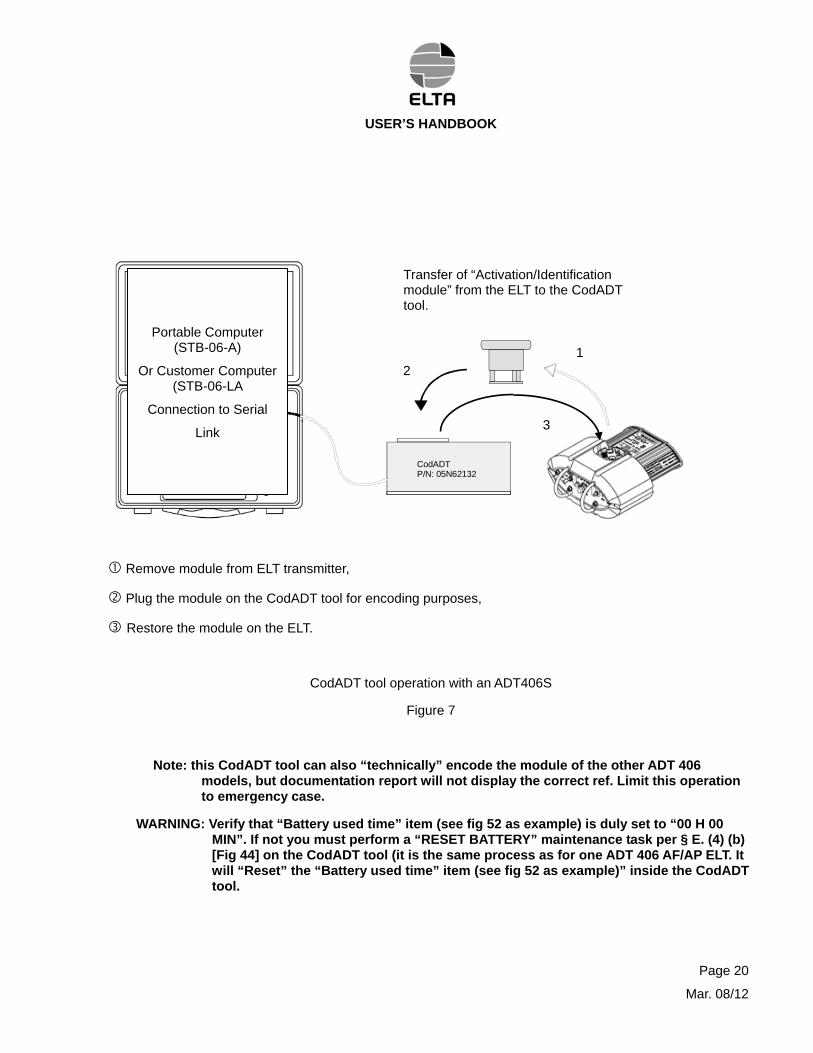
Transfer of “Activation/Identification module” from the ELT to the CodADT tool.
Remove module from ELT transmitter,
Plug the module on the CodADT tool for encoding purposes,
Restore the module on the ELT.
CodADT tool operation with an ADT406S
Figure 7
Note: this CodADT tool can also “technically” encode the module of the other ADT 406 models, but documentation report will not display the correct ref. Limit this operation to emergency case.
WARNING: Verify that “Battery used time” item (see fig 52 as example) is duly set to “00 H 00 MIN”. If not you must perform a “RESET BATTERY” maintenance task per § E. (4) (b) [Fig 44] on the CodADT tool (it is the same process as for one ADT 406 AF/AP ELT. It will “Reset” the “Battery used time” item (see fig 52 as example)” inside the CodADT tool.
Page 20
Mar. 08/12
USER’S HANDBOOK
(5) Connection Cables
The connection cables are divided in four categories: the power supply cables, the programming cables, the Serial link cable and the RF cables.
- The two power supply cables are used to power the Test Interface Device and the portable computer when the test bench is not working in autonomous mode.
- The four programming cables for connecting the Test Interface Device PROG connector to the different ELT transmitters, CodADT tool or Programming Box:
For the Programming Box of the ELT model A06V2, use the P/N 96N9028 cables,
For the A06V2 ELT transmitter, use the P/N 96N9029 extension cables associated to the P/N 96N9028 cable. They are connected to the ELT TC connector and to the Test Interface Device PROG connector,
For the ADT406 ELT and the CodADT, use the P/N 02N65746 cable connected to the ELT Remote Control connector,
For the A06 or A06V1 or A06T or S06 ELT, use the P/N 93N6222 cable connected to the ELT TC connector,
- USB / RS232 adapter + RS232 cable P/N 94N6493. This cable plus the USB / RS232 adapter are used to connect the Test Interface Device (COMP connector) to the portable computer (USB connector). For STB-06-LA use only RS232 connection cable P/N 95N6072.
- the coaxial cable P/N 94N6460 is used for connecting the ELT ANT or EXT. ANT. connector or BACK UP ANT. to the Test Interface Device RF connector.
Note: A standard TNC/BNC adapter is supplied for ELT model A06xx/S06 RF connections.
Page 21
Mar. 08/12
USER’S HANDBOOK
4. OPERATION
The STB-06-A test bench is designed to operate on shop External Power Supply or autonomously (Internal Power Supply made by a battery pack).
The STB-06-LA test bench is designed to operate on External Power Supply only.
These test benches can remain in storage for few weeks without being recharged.
A. External Power Supply operation
The STB-06-A test bench External Power Supply can operate with voltages between 100 V and 240 V, 50 Hz or 60 Hz. Power consumption is lower than 1 A.
Fully charging the battery takes approximately 5 hours (nominal).
B. Returning to service after long-duration storage
Long-duration storage causes full discharge of batteries. Fast charging of the computer battery and the Test Interface Device are necessary.
For charging:
- Connect the External Power supply adapters of each part directly to the relevant external power supply input.
- Charge the test bench assembly for approximately 5 hours.
Note: The nominal battery capacity is only achieved after several complete recharging / discharging Cycles.
Note: The test bench may be used immediately if it remains connected to external power supply.
Page 22
Mar. 08/12

USER’S HANDBOOK
C. Putting into service
For STB-06-LA: follow the complete procedure except those related to the portable computer. If required USB/ RS232 adapter may be applicable (no physical serial link on the PC computer).
(1)Preliminary operation
Open the case and check that the following components are present and in good condition:
- Test Interface Device,
- Portable Computer, with floppy disk drive,
- External Power Supply Adapter,
- CodADT tool,
- CDROM Drive,
- Connection Cables,
- USB / RS232 adapter (for portable computer),
Make sure that:
- The computer is connected to the Test Interface Device (COMP connector) with the RS232 cable P/N: 94N6493 and the USB / RS 232 adapter,
- The coaxial cable is connected to the Test Interface Device (RF connector),
- The portable computer is powered from its External Power Supply Adapter (if not it is in portable configuration),
- The Test Interface Device is powered from its External Power Supply Adapter (if not it is in portable configuration),
Note: Use the international Plug Adapter as necessary.
Page 23
Mar. 08/12
USER’S HANDBOOK
Page 24
Mar. 08/12
(2) Putting test bench into service
When the test bench is used in autonomous mode, do not perform the procedure described below but go straight to paragraph (b) Switching on the computer
(a)Connect the test bench to the power supply
- Take the External Power supply adapter out of the case. Connect it to the External Power supply and to the DC connector input of the computer.
- Connect the Test Interface Device External Power supply adapter to the External Power Supply and to DC 12V IN connector of the Test Interface Device.
- Indicator of the Test Interface Device becomes red (battery charging in progress).
(b)Switching ON the portable computer (STB-06-A only).
- Power the portable computer by pressing the push-button at the topside of the keyboard. After a few seconds, the computer screen comes on.
- A MICROSOFT welcome screen, then a "Windows XP" page is displayed. Wait until the STB-06-A icon is displayed and follow instructions displayed on screen.
Note: Normally the STB-06-A software is launched automatically. If not then double click on the STB-06 icon on the screen.
Note: For STB-06-LA software application, double click on the STB-06 icon on the screen.
USER’S HANDBOOK
D. Software installation (STB-06-LA, laboratory version, or STB-06-A recovery)
(1) STB-06 application software :
(a)The software can be used with WINDOWS 98, 2000, XP or NT.
- insert the first floppy disk in the drive, or use the CDROM if a drive is available.
- open the STB-06 directory if the software is not launched automatically,
- execute the SETUP file,
- follow the indicated instructions,
Four main screens (Ref. Fig 8) will appears in sequence:
Software Installation Screens
Figure 8
Note: The answer must be YES for the STB-06-A (fully portable version).Test bench software will run automatically at each computer power ON.
Note: The answer must be NO for the STB-06-LA (Work Shop version). Test bench software will run on operator request
Page 25
Mar. 08/12
USER’S HANDBOOK
(b)The software can now be used with WINDOWS 7 but some manual adjustments are required
Insert STB-06 software CD ROM in the CD ROM drive.
Interrupt the automatic installation if it runs after CDROM insertion
Under Windows 7 (or Vista as well), It is mandatory to install these software’ and run them under computer administrator right.
Software Installation under administrator right:
o Open the CD ROM, copy « setup.exe » and « setup.2 » in a dedicated Windows 7 new directory (for example : create a directory name « Install » under desktop and paste the two setup files from the CD ROM).
o Change the « properties » of setup.exe file -> tick « Run this program in compatibility mode for Windows XP (Service Pack 3) & tick “Run this program as an administrator
Tick this box
Tick this box
o Duly install the STB-06 software by running -> setup.exe. A warning box will open
Page 26
Mar. 08/12
USER’S HANDBOOK
Answer « Yes » and follow installation instructions (same process as for Windows XP, see Figure 8).
Software preparation in order to use them as administrator :
Locate the STB_06 icon under « Program Files (x86)/ELTA/STB-06-V1.2.8.0 » and modify the file properties (right click)
Software installation as administrator
Click this box to run software under Windows XP compatibility
IMPORTANT REMINDER :
- Every time you will run this software this warning box will open .
Answer « Yes ».
Page 27
Mar. 08/12
USER’S HANDBOOK
Page 28
Mar. 08/12
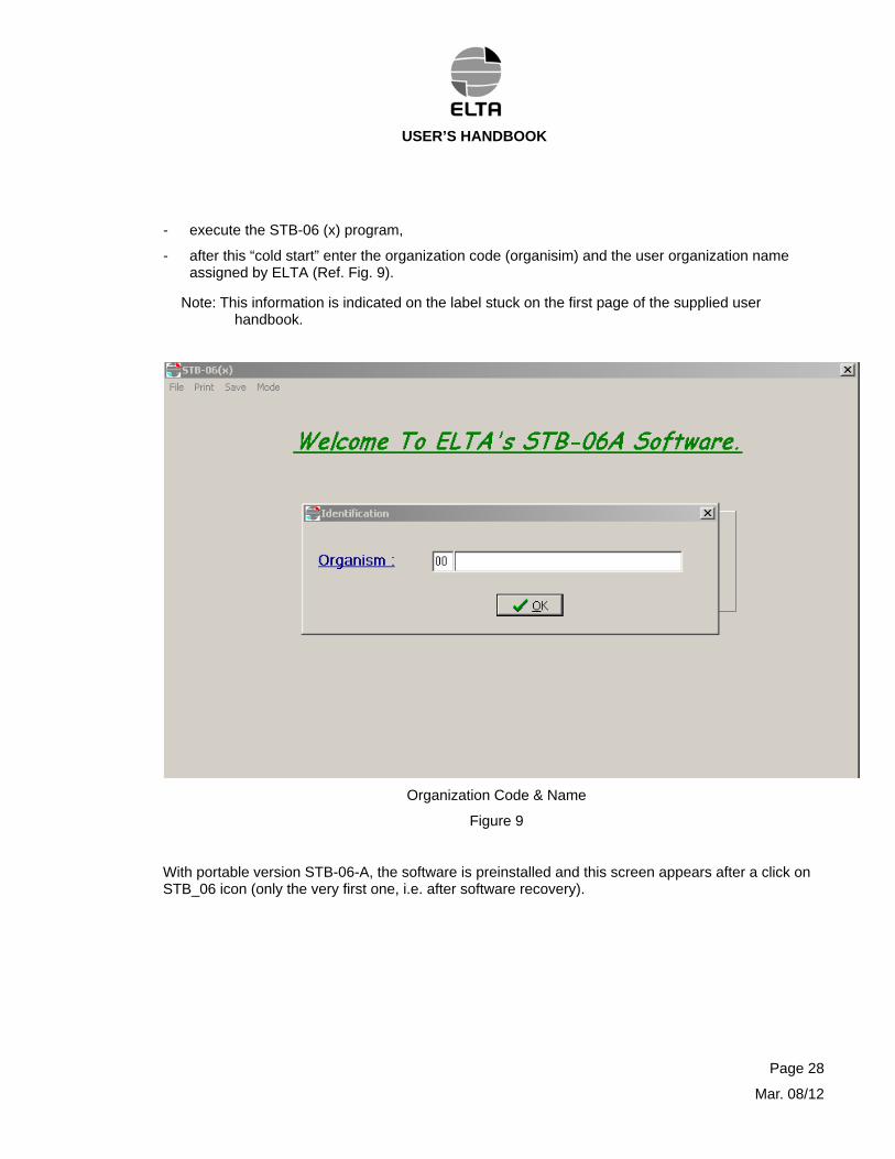
- execute the STB-06 (x) program,
- after this “cold start” enter the organization code (organisim) and the user organization name assigned by ELTA (Ref. Fig. 9).
Note: This information is indicated on the label stuck on the first page of the supplied user handbook.
Organization Code & Name
Figure 9
With portable version STB-06-A, the software is preinstalled and this screen appears after a click on STB_06 icon (only the very first one, i.e. after software recovery).
USER’S HANDBOOK
(2) USB / RS232 driver (STB-06-A software recovery only)
The use of an USB / RS232 adapter is necessary with a portable computer only equipped with USB port.
This USB / RS232 adapter require a driver initially installed by ELTA at the same time as STB-06-A software. .
This driver must be reinstalled in the event of complete computer software recovery.
Use the CDROM supplied with the USB/SERIAL interface and follow the instructions given by the USB/SERIAL interface manufacturer.
(3)Decimal symbol configuration verification
IMPORTANT :
For correct access to « spec.ini » information it is important to verify that the PC operating system is set correctly with the decimal symbol. It should be set to dot « . » and not to coma « , ».
If not, the content of “spec.ini” will not be taken into account and software default values will apply.
On standard PC computer, access the decimal symbol configuration as indicated here under
“Control Panel
-> Date, Time, Language, and Regional Options
-> Regional and Language Options
-> Regional Options (English?)
-> Customize….
-> Numbers
-> Decimal symbol & verify it is duly “. “ (dot)
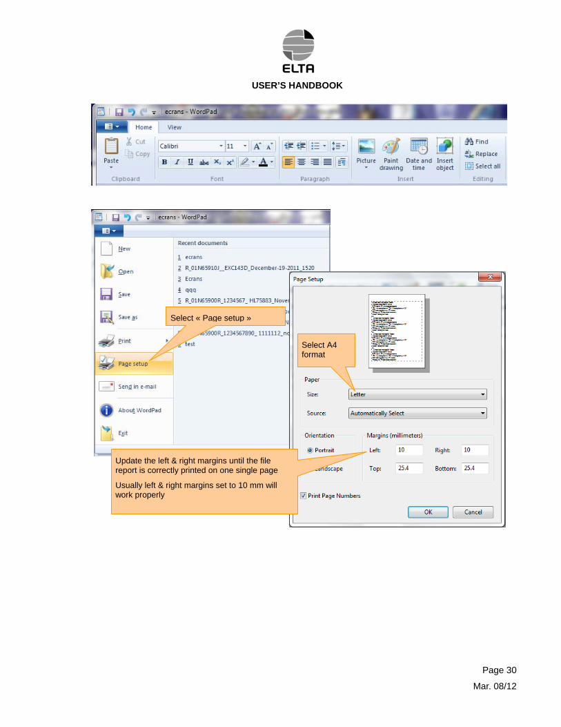
(4)For correct test reports prints, check WordPad configuration (page margins)
Test reports created by STB06 software under directory « save » can be read directly with Wordpad (recommended), do not use Word as it will incorporate controls characters).
Using standard configuration of Wordpad may cause paging failure (report not correctly presented on one single page, (format trouble)
Solving this issue is simple, it just need you to modify Wordpad configuration.
To do so open Wordpad then
Open this function
Page 29
Mar. 08/12
USER’S HANDBOOK
Select « Page setup »
Select A4 format
Update the left & right margins until the file report is correctly printed on one single page
Usually left & right margins set to 10 mm will work properly
Page 30
Mar. 08/12
USER’S HANDBOOK
E. Functional test of ELT
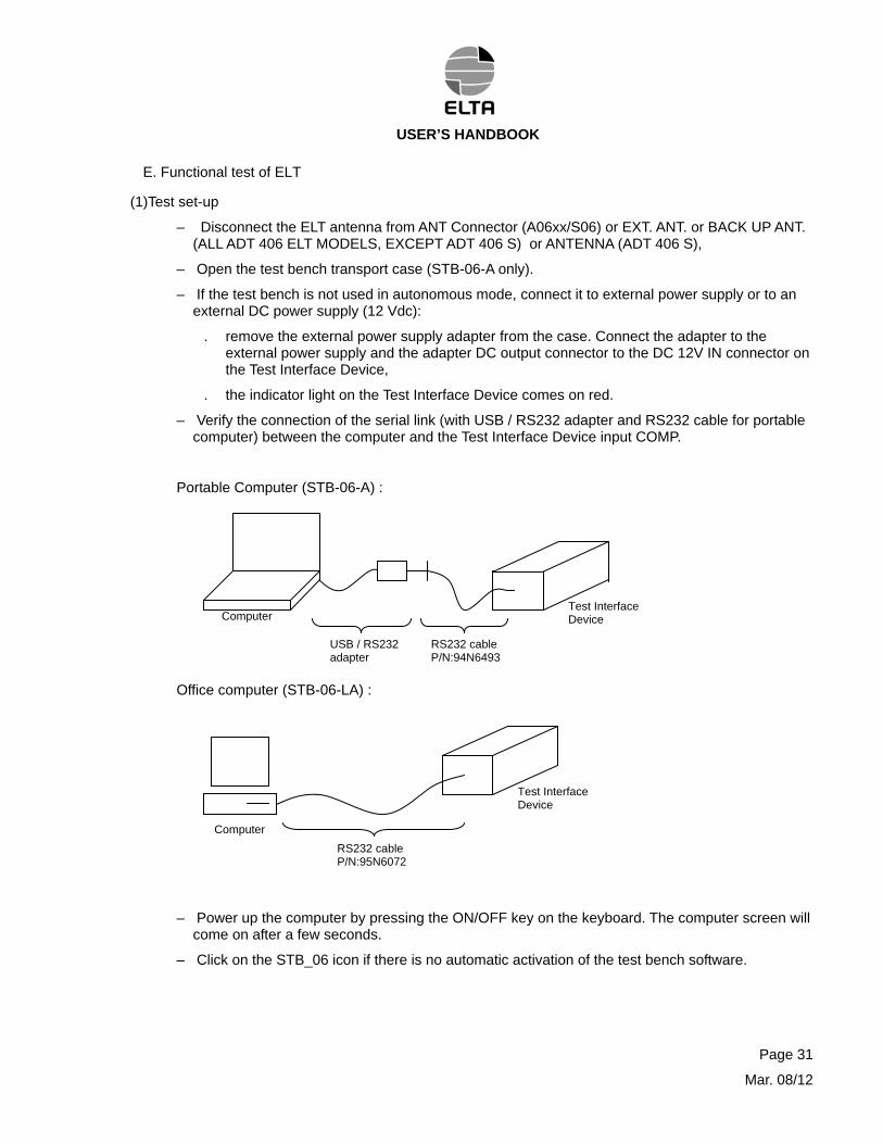
(1)Test set-up
– Disconnect the ELT antenna from ANT Connector (A06xx/S06) or EXT. ANT. or BACK UP ANT. (ALL ADT 406 ELT MODELS, EXCEPT ADT 406 S) or ANTENNA (ADT 406 S),
– Open the test bench transport case (STB-06-A only).
– If the test bench is not used in autonomous mode, connect it to external power supply or to an external DC power supply (12 Vdc):
. remove the external power supply adapter from the case. Connect the adapter to the external power supply and the adapter DC output connector to the DC 12V IN connector on the Test Interface Device,
. the indicator light on the Test Interface Device comes on red.
– Verify the connection of the serial link (with USB / RS232 adapter and RS232 cable for portable computer) between the computer and the Test Interface Device input COMP.
Portable Computer (STB-06-A) :
Office computer (STB-06-LA) :
Computer Test Interface Device
USB / RS232 adapter
RS232 cable P/N:94N6493
Test Interface Device
Computer
RS232 cable P/N:95N6072
– Power up the computer by pressing the ON/OFF key on the keyboard. The computer screen will come on after a few seconds.
– Click on the STB_06 icon if there is no automatic activation of the test bench software.
Page 31
Mar. 08/12
USER’S HANDBOOK
(2)Test procedure
(a)Test bench initialization and explanation of its functions and screens
If the title screen is not displayed click Mode and then click Test Device.
Note: The Operator can perform tasks by using mouse or shortcut keys. For example: press T key on the keyboard to select Test (underlined letter).
By default STB-06-A test bench is using USB / RS232 adapter with com port # set to 4 : i.e;
Port Num = 4
The STB-06 test bench software is trying in sequence Port Num = 4, then propose to use
Port Num = 1.
If the USB/SERIAL is not set on one of these number, then it display a general error box for a manual resolution.
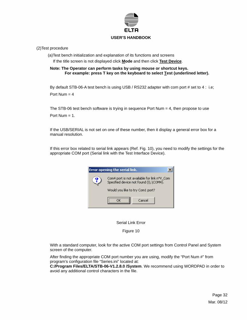
If this error box related to serial link appears (Ref. Fig. 10), you need to modify the settings for the appropriate COM port (Serial link with the Test Interface Device).
Serial Link Error
Figure 10
With a standard computer, look for the active COM port settings from Control Panel and System screen of the computer.
After finding the appropriate COM port number you are using, modify the “Port Num #” from program’s configuration file “Series.ini” located at: C:/Program Files/ELTA/STB-06-V1.2.8.0 /System. We recommend using WORDPAD in order to avoid any additional control characters in the file.
Page 32
Mar. 08/12
USER’S HANDBOOK
Page 33
Mar. 08/12
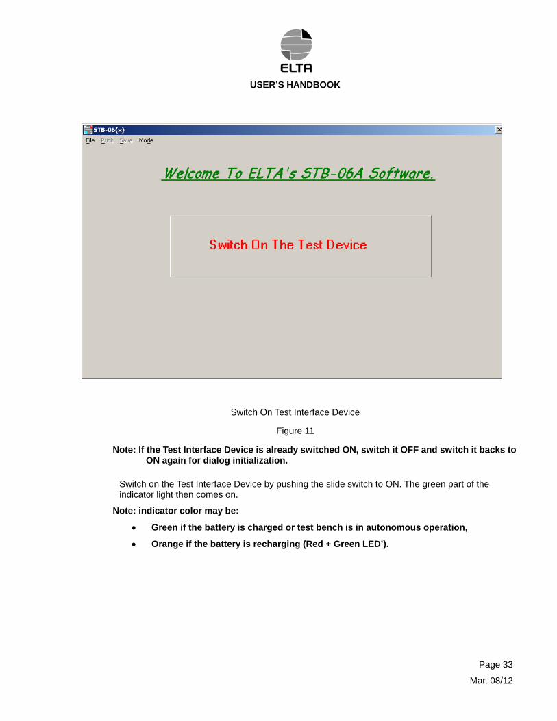
Switch On Test Interface Device
Figure 11
Note: If the Test Interface Device is already switched ON, switch it OFF and switch it backs to ON again for dialog initialization.
Switch on the Test Interface Device by pushing the slide switch to ON. The green part of the indicator light then comes on.
Note: indicator color may be:
Green if the battery is charged or test bench is in autonomous operation,
Orange if the battery is recharging (Red + Green LED’).
USER’S HANDBOOK
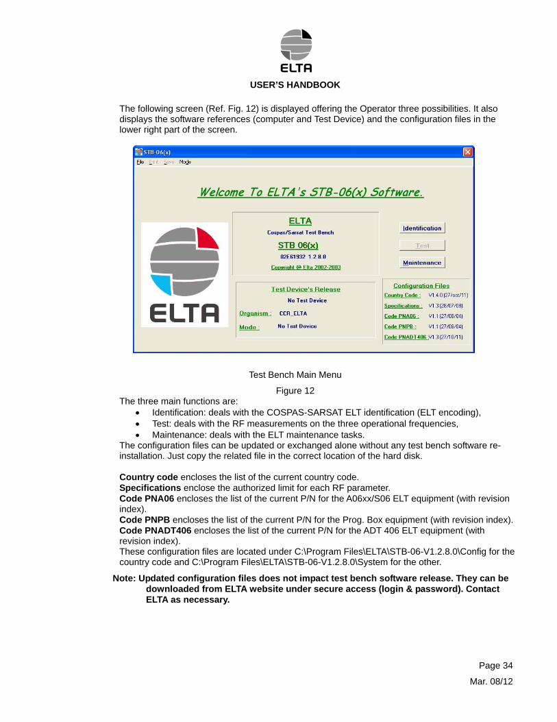
The following screen (Ref. Fig. 12) is displayed offering the Operator three possibilities. It also displays the software references (computer and Test Device) and the configuration files in the lower right part of the screen.
Test Bench Main Menu
Figure 12 The three main functions are:
Identification: deals with the COSPAS-SARSAT ELT identification (ELT encoding), Test: deals with the RF measurements on the three operational frequencies, Maintenance: deals with the ELT maintenance tasks.
The configuration files can be updated or exchanged alone without any test bench software re-installation. Just copy the related file in the correct location of the hard disk. Country code encloses the list of the current country code. Specifications enclose the authorized limit for each RF parameter. Code PNA06 encloses the list of the current P/N for the A06xx/S06 ELT equipment (with revision index). Code PNPB encloses the list of the current P/N for the Prog. Box equipment (with revision index). Code PNADT406 encloses the list of the current P/N for the ADT 406 ELT equipment (with revision index). These configuration files are located under C:\Program Files\ELTA\STB-06-V1.2.8.0\Config for the country code and C:\Program Files\ELTA\STB-06-V1.2.8.0\System for the other.
Note: Updated configuration files does not impact test bench software release. They can be downloaded from ELTA website under secure access (login & password). Contact ELTA as necessary.
Page 34
Mar. 08/12
USER’S HANDBOOK
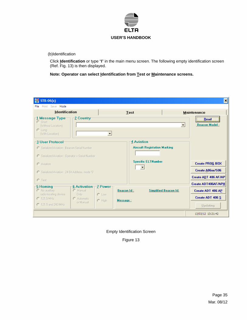
(b)Identification
Click Identification or type “I” in the main menu screen. The following empty identification screen (Ref. Fig. 13) is then displayed.
Note: Operator can select Identification from Test or Maintenance screens.
Empty Identification Screen
Figure 13
Page 35
Mar. 08/12
USER’S HANDBOOK
This screen deals with the COSPAS-SARSAT Identification selectable parameters.
It is used to provide the following information (Ref. Fig 13):
Note: Details of the COSPAS-SARSAT (C/S) identification can be found through the C/S Internet site at the address
http://www.cospas-sarsat.org/index.php?option=com_content&view=article&id=189&Itemid=118&lang=en
done in accordance with every local regulation.
- the message type : long or short (with or without location capability) (Item 1),
- the country name with the associated code (Item 2) as per ICAO or IMO
Note: Updated country code list can be consulted on the C/S Internet site at the address http://www.itu.int/online/mms/glad/cga_mids.sh for the list of MIDs, country code (web site of ITU).
- the user protocol (Item 3),
- the additional information corresponding to the protocol selected (Item 4),
- the radio location type (Item 5),
- the activation type (Item 6),
- the homing signals power selection when available (Item 7),
- the last box displays the official 15 Hex COSPAS-SARSAT Identification as “Beacon Id” and the simplified identification as “Simplified Beacon Id” (ELTA individual parameter display). See figure 27 for detail.
Note: Decoding of the 15 hex C/S identification can be performed on the C/S internet site at the address
http://www.cospas-sarsat.org/index.php?option=com_beacondecode&task=showBeacon&Itemid=85&lang=en
then click in the empty box, enter the relevant 15 Hex C/S ID code and click “Process”. Detail will then been displayed in the lower part of the screen.
Note: Final User Registration of ELT is now possible directly by Internet, when the local entity does not manage/ this capability after 16 January 2006 on the International Registration Database (IRB):
The actual International Registration Data Base is located at the address:
https://www.406registration.com/
Page 36
Mar. 08/12
USER’S HANDBOOK
1 Beacon ID verification
To perform this task the ELT transmitter or Programming Box or CodADT tool must be connected to the Test Interface Device PROG connector on one side with the relevant encoding cable:
For the Programming Box (Prog. Box) of the ELT model A06V2, use the P/N 96N9028 cable,
Note: Connect the Jaeger connector only to the Programming Box side and connect the other end to the PROG. Connector (Test Interface Device side) when the software asks to “Turn ON the beacon”.
For the A06V2 ELT transmitter, connect the P/N 96N9029 extension cable with the P/N 96N9028 cable. They are connected to the TC connector (ELT side) and to the PROG connector (Test Interface Device side),
For the ADT406 ELT or CodADT tool, use the P/N 02N65746 cable connected to the ELT REMOTE CONTROL connector (ELT side) and to the PROG connector (Test Interface Device side),
Note: the software automatically detects the CodADT tool.
For the A06 or A06V1 or A06T or S06 ELT, use the P/N 93N6222 cable connected to the TC connector (ELT side) and to the PROG connector (Test Interface Device side),
Click Read. The screen instructs the Operator to turn ON the ELT.
st
graph will display the data transfer, then the screen instructs the Operator to turn OFF the ELT.
Turn ON the ELT or the CodADT tool or connect the programming cable (P/N 96N9028) to the TeInterface Device when using the Programming Box of the A06V2 ELT.
A bar
Page 37
Mar. 08/12
USER’S HANDBOOK
Turn OFF the ELT transmitter or the CodADT tool or disconnect the encoding cable for the Programming Box from the Test Interface Device when turn OFF is requested.
An “Auto Save” screen (Ref. Fig. 14) is displayed requesting the operator to save the results of the test for further analyzes.
Example of Identification AutoSave Reading Screen
Figure 14
Fill the serial number field and we recommend to enter a remark (up to 40 characters) for further follow up ease, then click OK
Page 38
Mar. 08/12
USER’S HANDBOOK
The following screen (Ref. Fig. 15) is displayed.
Example of Identification Reading Screen
Figure 15
All the information acquired from the ELT, CodADT tool or Programming Box is displayed in Green.
Beacon Model is automatically displayed on the upper right of the screen.
Battery Used Time indicates the cumulative transmission duration of the transmitter (increased every 15 minutes).
Note: This information does not exist for the CodADT Tool and for the Programming Box.
Rate indicates the duration between two consecutive Cospas-Sarsat Burst,
Clock is the actual value of the ELT internal real time clock (Not UTC).
Note: Clock is not relevant for A06xx/S06, Prog.ox & ADT 406 S.
Page 39
Mar. 08/12

USER’S HANDBOOK
Page 40
Mar. 08/12
When the battery used time is over a limit, a warning box appears after identification Read. It recommends performing a battery servicing on the ELT transmitter. See following example in Figure 16 and 17.
Limit is adjusted to 5 hours with the ELT models ADT 406 (except for ADT 406 S, not relevant) and 2 hours with the ELT models A06xx/S06.
Battery Used Time Warning in Identification Screen for ADT 406
Figure 16
Battery Used Time Warning in Identification Screen for A06xx/S06
Figure 17
For closing the warning battery servicing, click OK then Turn OFF the ELT transmitter or disconnect the encoding cable from the Programming Box.
WARNING: FOR US OPERATOR THERE IS A FAR RULE REQUESTING TO PERFORM THE BATTERY SERVICING PROCESS AFTER A CUMULATIVE TRANSMISSION OF ONE HOUR.
USER’S HANDBOOK
2 Beacon ID creation or update
To perform this task the ELT transmitter or Programming Box or CodADT tool must be connected to the Test Interface Device PROG connector on one side with the relevant encoding cable:
For the Programming Box (Prog. Box) of the ELT model A06V2, use the P/N 96N9028 cable,
Note: Connect the Jaeger connector only to the Programming Box side and connect the other end to the PROG. Connector (Test Interface Device side) when the software asks to “Turn ON the beacon”.
For the A06V2 ELT transmitter, connect the P/N 96N9029 extension cable with the P/N 96N9028 cable. They are connected to the TC connector (ELT side) and to the PROG connector (Test Interface Device side),
For the ADT406 ELT or CodADT tool, use the P/N 02N65746 cable connected to the ELT REMOTE CONTROL connector (ELT side) and to the PROG connector (Test Interface Device side),
Note: the software automatically detects the CodADT tool.
For the A06 or A06V1 or A06T or S06 ELT, use the P/N 93N6222 cable connected to the TC connector (ELT side) and to the PROG connector (Test Interface Device side),
Click on Create A06xx/S06 to select a new or an other C/S identification for the A06xx or S06 ELT.
To create or update to a new C/S identification for Programming Box, click on Create PROG BOX.
To create or update to a new C/S identification for ADT 406 AF/AP, click on Create ADT 406 AF/AP.
To create or update to a new C/S identification for ADT 406 AF/AP-H, click on Create ADT 406 AF/APH.
To create or update to a new C/S identification for ADT 406 AP, click on Create ADT 406 AP.
To create or update to a new C/S identification for ADT 406 S, click on Create ADT 406 S and use the CodADT tool interface to receive the Activation/Identification module.
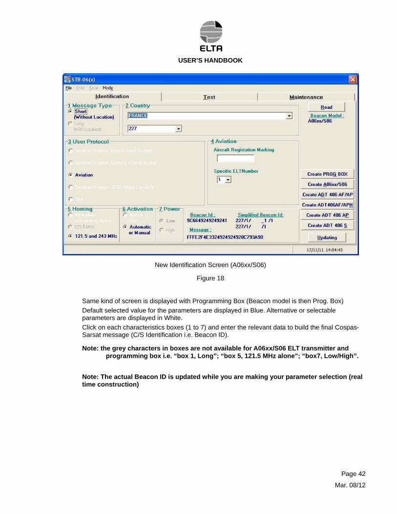
The following screen (Ref. Fig. 18) is displayed.
Parameters in Box 1; 2; 3; 4; 5 are related to Cospas-Sarsat Identification and modify the Beacon ID content.
Parameter on Box 6 is related to Cospas-Sarsat but is “for information only” and consequently does not appear in the Beacon ID content (so beacon ID content is not impacted nor modified by this information).
Parameter in Box 7 is only operational for one version of ELT: the model ADT 406 AF/AP. By default we select “High” value and we recommend keeping this selection.
Note: Previously the power was indicated as 20 and 23 dBm, now ELTA modified the display and we are using Low (corresponding to former 20 dBm) and High (Corresponding to former 23 dBm). This presentation is more versatile.
Page 41
Mar. 08/12
USER’S HANDBOOK
New Identification Screen (A06xx/S06)
Figure 18
Same kind of screen is displayed with Programming Box (Beacon model is then Prog. Box)
Default selected value for the parameters are displayed in Blue. Alternative or selectable parameters are displayed in White.
Click on each characteristics boxes (1 to 7) and enter the relevant data to build the final Cospas-Sarsat message (C/S Identification i.e. Beacon ID).
Note: the grey characters in boxes are not available for A06xx/S06 ELT transmitter and programming box i.e. “box 1, Long”; “box 5, 121.5 MHz alone”; “box7, Low/High”.
Note: The actual Beacon ID is updated while you are making your parameter selection (real time construction)
Page 42
Mar. 08/12
USER’S HANDBOOK
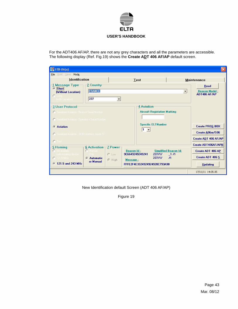
For the ADT406 AF/AP, there are not any grey characters and all the parameters are accessible. The following display (Ref. Fig.19) shows the Create ADT 406 AF/AP default screen.
New Identification default Screen (ADT 406 AF/AP)
Figure 19
Page 43
Mar. 08/12
USER’S HANDBOOK
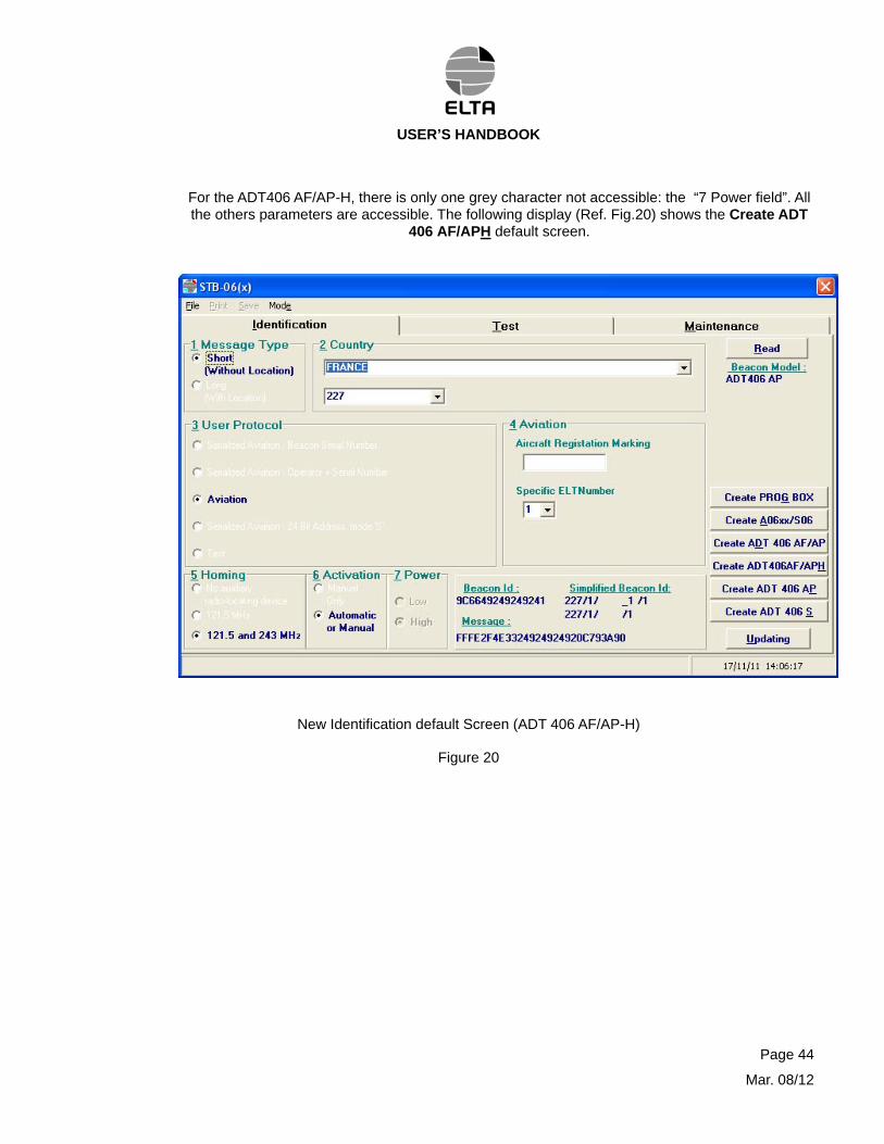
For the ADT406 AF/AP-H, there is only one grey character not accessible: the “7 Power field”. All the others parameters are accessible. The following display (Ref. Fig.20) shows the Create ADT
406 AF/APH default screen.
New Identification default Screen (ADT 406 AF/AP-H)
Figure 20
Page 44
Mar. 08/12
USER’S HANDBOOK
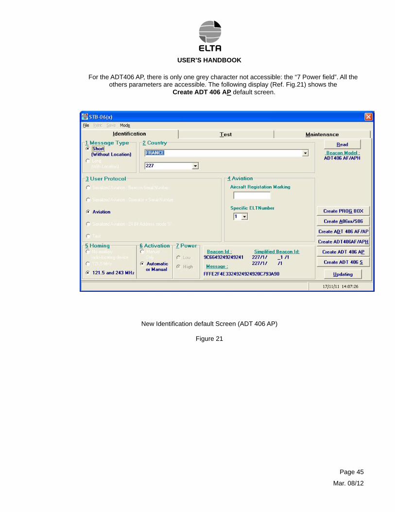
For the ADT406 AP, there is only one grey character not accessible: the “7 Power field”. All the others parameters are accessible. The following display (Ref. Fig.21) shows the
Create ADT 406 AP default screen.
New Identification default Screen (ADT 406 AP)
Figure 21
Page 45
Mar. 08/12
USER’S HANDBOOK
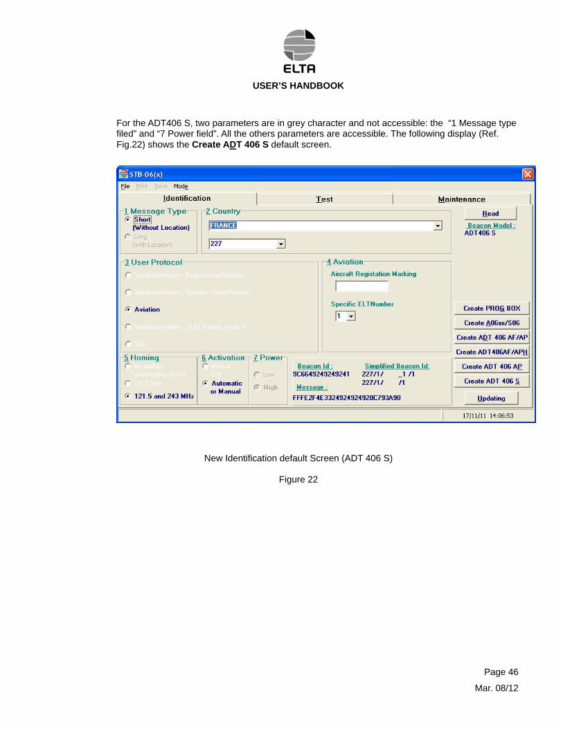
For the ADT406 S, two parameters are in grey character and not accessible: the “1 Message type filed” and “7 Power field”. All the others parameters are accessible. The following display (Ref. Fig.22) shows the Create ADT 406 S default screen.
New Identification default Screen (ADT 406 S)
Figure 22
Page 46
Mar. 08/12

USER’S HANDBOOK
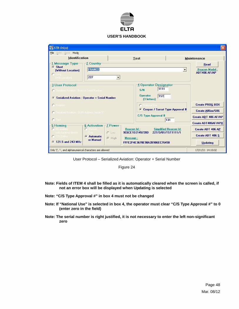
The following screens show the different user protocols (Ref. Fig. 23 to 27):
Note: Beacon model ADT 406 AF/AP is given as example but same screens exists for A06xx, Programming Box and other ADT 406 models. Please remember that the grey characters in boxes are not available for A06xx/S06 ELT transmitter and programming box i.e. “box 1, Long”; “box 5, 121.5 MHz alone”; “box7, Low/High”.
User Protocol - Serialized Aviation: ELT Serial Number
Figure 23
Note: Fields of ITEM 4 shall be filled as it is automatically cleared when the screen is called if not an error box will be displayed when Updating is selected
Note: “C/S Type Approval #” in box 4 must not be changed
Note: If “National Use” is selected in box 4, the operator must clear “C/S Type Approval #” to 0 (enter zero in the field)
Note: The serial number is right justified, it is not necessary to enter the left non-significant zero
Page 47
Mar. 08/12
USER’S HANDBOOK
User Protocol – Serialized Aviation: Operator + Serial Number
Figure 24
Note: Fields of ITEM 4 shall be filled as it is automatically cleared when the screen is called, if not an error box will be displayed when Updating is selected
Note: “C/S Type Approval #” in box 4 must not be changed
Note: If “National Use” is selected in box 4, the operator must clear “C/S Type Approval #” to 0 (enter zero in the field)
Note: The serial number is right justified, it is not necessary to enter the left non-significant zero
Page 48
Mar. 08/12
USER’S HANDBOOK
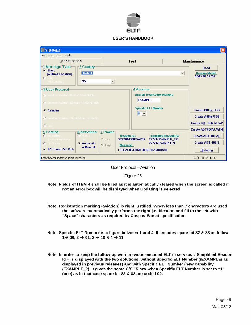
User Protocol – Aviation
Figure 25
Note: Fields of ITEM 4 shall be filled as it is automatically cleared when the screen is called if not an error box will be displayed when Updating is selected
Note: Registration marking (aviation) is right justified. When less than 7 characters are used the software automatically performs the right justification and fill to the left with “Space” characters as required by Cospas-Sarsat specification
Note: Specific ELT Number is a figure between 1 and 4. It encodes spare bit 82 & 83 as follow 1 00, 2 01, 3 10 & 4 11
Note: In order to keep the follow-up with previous encoded ELT in service, « Simplified Beacon Id » is displayed with the two solutions, without Specific ELT Number (/EXAMPLE/ as displayed in previous releases) and with Specific ELT Number (new capability, /EXAMPLE_2). It gives the same C/S 15 hex when Specific ELT Number is set to “1” (one) as in that case spare bit 82 & 83 are coded 00.
Page 49
Mar. 08/12
USER’S HANDBOOK
Page 50
Mar. 08/12
User Protocol – Serialized Aviation: 24 Bit Address, Mode 'S'
Figure 26
Note: In box 4, the operator shall assign the ELT index on board A/C (0 for the first one, 1…).
Note: The 24 bit address may be entered either in decimal (conversion from 24 bit binary to decimal) or in HEX (conversion from 24 bit binary to Hex value). Value is right justified.
Note: To keep traceability with the previous ELT in service, Simplified Beacon ID is displayed in two notations, decimal (/001073430/ in the above screen) and in Hex (new capability, /H_01A34F_0/). The last digit is the ELT index on board the A/C. The operator will select which one he wants to use on the ELT Identification label. Official beacon ID is not impacted by this choice (only screen display).
Note: Fields of ITEM 4 shall be filled as it is automatically cleared when the screen is called if not an error box will be displayed when Updating is selected
Note: “C/S Type Approval #” in box 4 must not be changed
Note: If “National Use” is selected in box 4, the operator must clear “C/S Type Approval #” to 0 (enter zero in the field).
USER’S HANDBOOK
User Protocol – Test
Figure 27
Note: For the test protocol we recommend that the Homing signals be removed in order to avoid false alert. The Cospas-Sarsat message for test protocol is not processed by the Cospas-Sarsat system. This “TEST” transmission is considered as Non Operational and is discarded by the system unless the operator contact the nearest Cospas-Sarsat MCC and ask to receive the information (location, message….).
Note: Fields of ITEM 4 shall be filled as it is automatically cleared when the screen is called if not an error box will be displayed when Updating is selected
CAUTION: THIS TEST PROTOCOL IS NOT OPERATIONAL. IT MUST NOT BE USE FOR NORMAL OPERATION ONBOARD AN A/C. THE GOAL OF THIS SPECIAL PROTOCOL IS TO ALLOW THE POSSIBILITY TO PERFORM REAL TRANSMISSION TEST THROUGH SATELLITE, BUT IT REMAIN LOCAL AND SHOULD BE COORDINATED WITH LOCAL C/S ENTITY (MCC)
Page 51
Mar. 08/12
USER’S HANDBOOK
Upon completion of the parameters selection, click Updating to download the new identification in the ELT or in the CodADT tool. The screen instructs the Operator to turn ON the ELT.
Turn ON the ELT transmitter or the CodADT tool or connect the encoding cable for the programming box of the A06V2. The downloading of the data starts. When the downloading is over the screen instructs the Operator to turn OFF the ELT.
Turn OFF the ELT or the CodADT tool or disconnect the programming cable for the programming box of the A06V2. The following AutoSave screen (Ref. Fig. 28) is displayed.
Identification Updated AutoSave Screen (Aviation Example)
Figure 28
Fill the serial number field and we recommend to enter a remark (up to 40 characters) for further follow up ease, then click OK
Page 52
Mar. 08/12
USER’S HANDBOOK
The following Update screen (Ref. Fig. 29) is displayed.
Identification Updated Screen (Aviation Example)
Figure 29
The message "Update Successful" appears in the left down corner of the screen.
The ELT Identified Simplified Decoding Table (Figure 30) is used to display the ELT Cospas-Sarsat Identification in the Identification Box. This presentation will ease the comprehension of the main COSPAS-SARSAT identification fields.
CAUTION:
PLEASE NOTE THAT THE OFFICIAL COSPAS-SARSAT IDENTIFICATION IS MADE OF THE 15 HEX DIGITS OF THE “BEACON ID:” IN THE IDENTIFICATION BOX
Page 53
Mar. 08/12
USER’S HANDBOOK
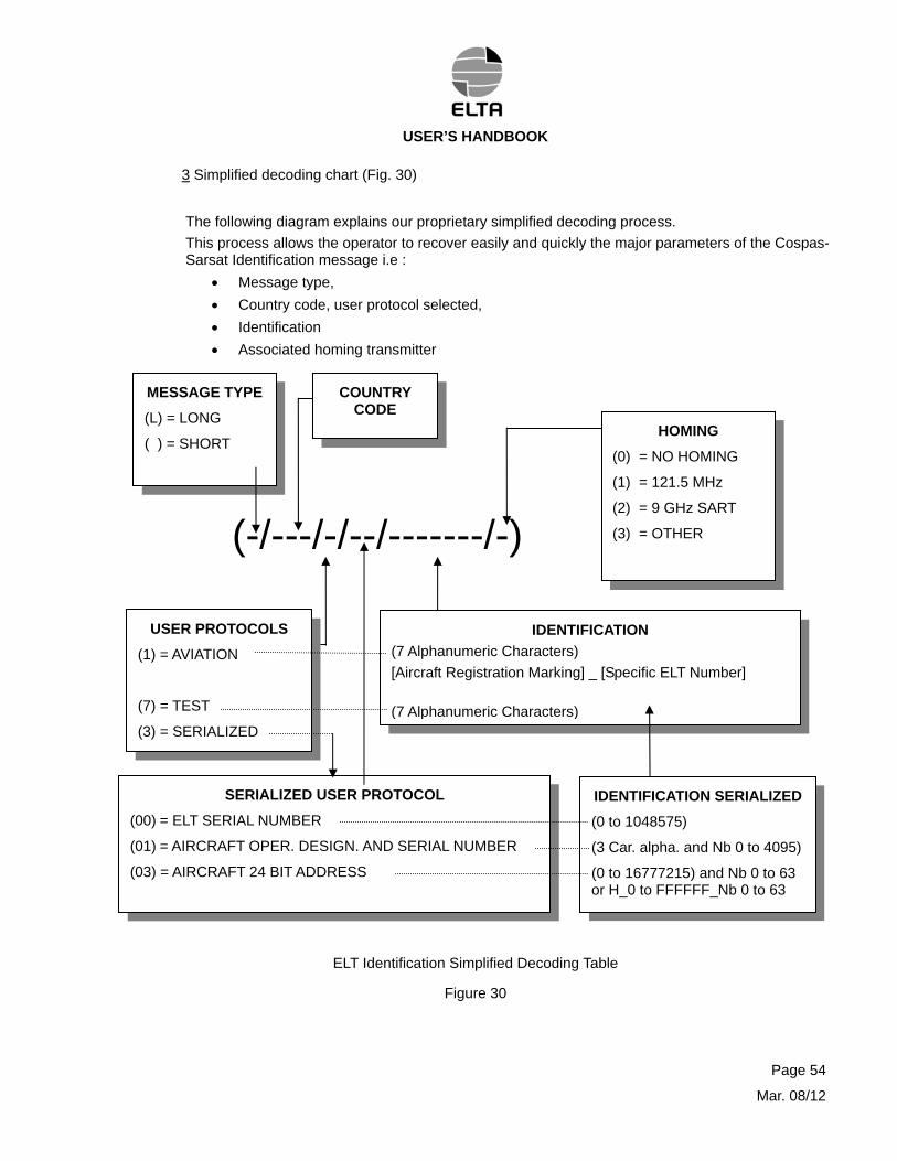
3 Simplified decoding chart (Fig. 30)
The following diagram explains our proprietary simplified decoding process.
This process allows the operator to recover easily and quickly the major parameters of the Cospas-Sarsat Identification message i.e :
Message type,
Country code, user protocol selected,
Identification
Associated homing transmitter
(-/---/-/--/-------/-)
COUNTRY CODE
USER PROTOCOLS
(1) = AVIATION
(7) = TEST
(3) = SERIALIZED
IDENTIFICATION
(7 Alphanumeric Characters)
[Aircraft Registration Marking] _ [Specific ELT Number]
(7 Alphanumeric Characters)
IDENTIFICATION SERIALIZED
(0 to 1048575)
(3 Car. alpha. and Nb 0 to 4095)
(0 to 16777215) and Nb 0 to 63 or H_0 to FFFFFF_Nb 0 to 63
SERIALIZED USER PROTOCOL
(00) = ELT SERIAL NUMBER
(01) = AIRCRAFT OPER. DESIGN. AND SERIAL NUMBER
(03) = AIRCRAFT 24 BIT ADDRESS
HOMING
(0) = NO HOMING
(1) = 121.5 MHz
(2) = 9 GHz SART
(3) = OTHER
MESSAGE TYPE
(L) = LONG
( ) = SHORT
ELT Identification Simplified Decoding Table
Figure 30
Page 54
Mar. 08/12
USER’S HANDBOOK
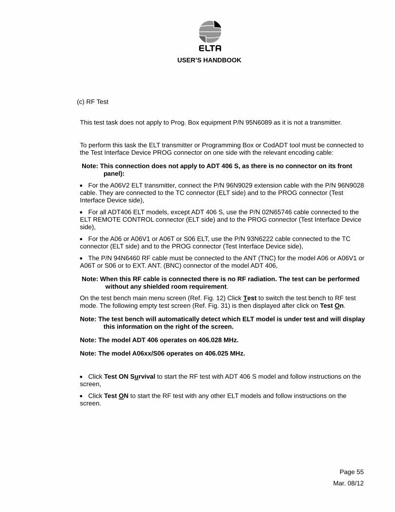
(c) RF Test
This test task does not apply to Prog. Box equipment P/N 95N6089 as it is not a transmitter.
To perform this task the ELT transmitter or Programming Box or CodADT tool must be connected to the Test Interface Device PROG connector on one side with the relevant encoding cable:
Note: This connection does not apply to ADT 406 S, as there is no connector on its front panel):
For the A06V2 ELT transmitter, connect the P/N 96N9029 extension cable with the P/N 96N9028 cable. They are connected to the TC connector (ELT side) and to the PROG connector (Test Interface Device side),
For all ADT406 ELT models, except ADT 406 S, use the P/N 02N65746 cable connected to the ELT REMOTE CONTROL connector (ELT side) and to the PROG connector (Test Interface Device side),
For the A06 or A06V1 or A06T or S06 ELT, use the P/N 93N6222 cable connected to the TC connector (ELT side) and to the PROG connector (Test Interface Device side),
The P/N 94N6460 RF cable must be connected to the ANT (TNC) for the model A06 or A06V1 or A06T or S06 or to EXT. ANT. (BNC) connector of the model ADT 406,
Note: When this RF cable is connected there is no RF radiation. The test can be performed without any shielded room requirement.
On the test bench main menu screen (Ref. Fig. 12) Click Test to switch the test bench to RF test mode. The following empty test screen (Ref. Fig. 31) is then displayed after click on Test On.
Note: The test bench will automatically detect which ELT model is under test and will display this information on the right of the screen.
Note: The model ADT 406 operates on 406.028 MHz.
Note: The model A06xx/S06 operates on 406.025 MHz.
Click Test ON Survival to start the RF test with ADT 406 S model and follow instructions on the screen,
Click Test ON to start the RF test with any other ELT models and follow instructions on the screen.
Page 55
Mar. 08/12
USER’S HANDBOOK
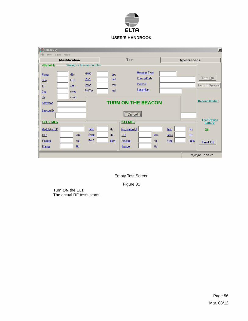
Empty Test Screen
Figure 31
Turn ON the ELT. The actual RF tests starts.
Page 56
Mar. 08/12
USER’S HANDBOOK
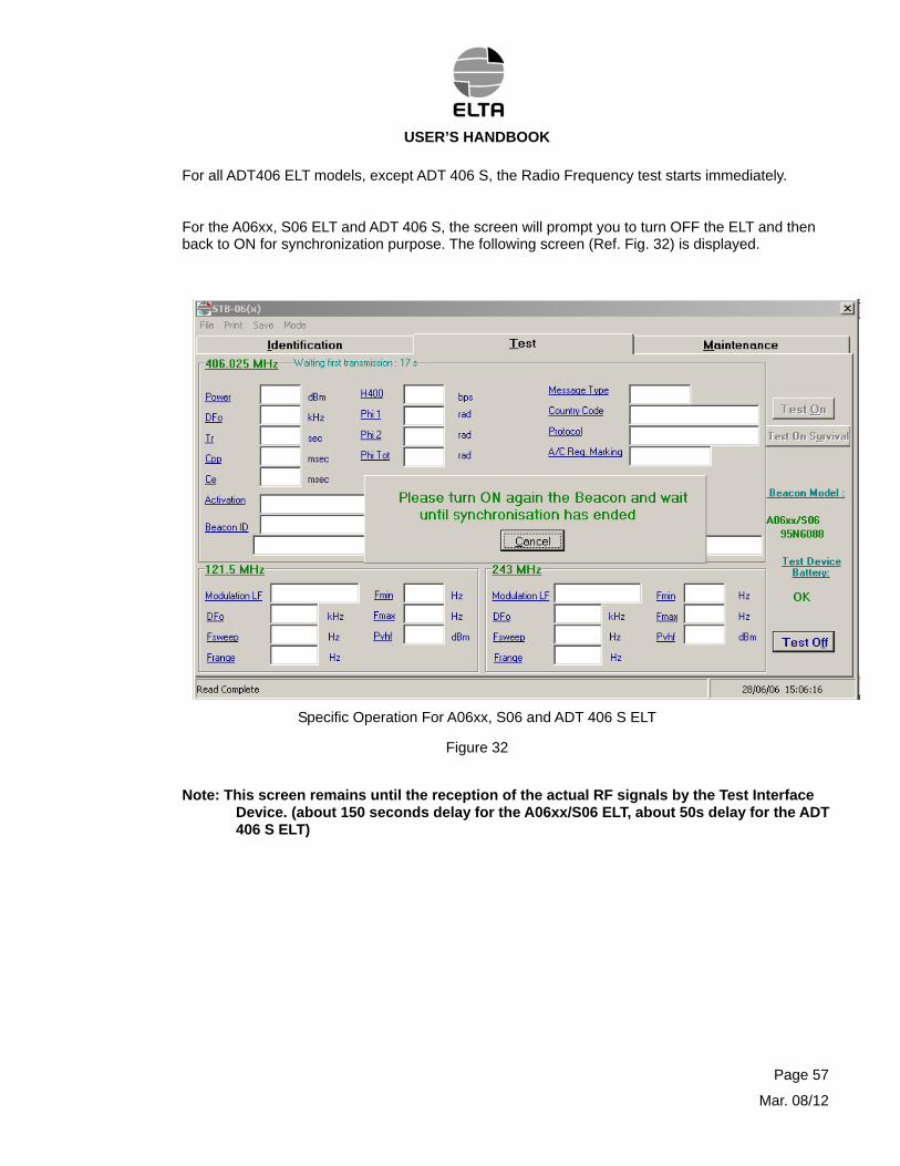
For all ADT406 ELT models, except ADT 406 S, the Radio Frequency test starts immediately.
For the A06xx, S06 ELT and ADT 406 S, the screen will prompt you to turn OFF the ELT and then back to ON for synchronization purpose. The following screen (Ref. Fig. 32) is displayed.
Specific Operation For A06xx, S06 and ADT 406 S ELT
Figure 32
Note: This screen remains until the reception of the actual RF signals by the Test Interface Device. (about 150 seconds delay for the A06xx/S06 ELT, about 50s delay for the ADT 406 S ELT)
Page 57
Mar. 08/12
USER’S HANDBOOK
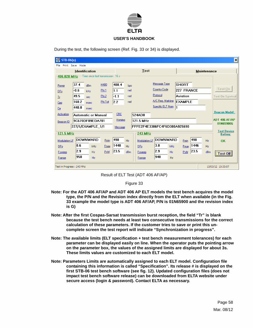
During the test, the following screen (Ref. Fig. 33 or 34) is displayed.
Result of ELT Test (ADT 406 AF/AP)
Figure 33
Note: For the ADT 406 AF/AP and ADT 406 AP ELT models the test bench acquires the model type, the P/N and the Revision index directly from the ELT when available (in the Fig. 33 example the model type is ADT 406 AF/AP, P/N is 01N65900 and the revision index is G)
Note: After the first Cospas-Sarsat transmission burst reception, the field “Tr” is blank because the test bench needs at least two consecutive transmissions for the correct calculation of these parameters. If the customer tries to save or print this un-complete screen the test report will indicate “Synchronization in progress”.
Note: The available limits (ELT specification + test bench measurement tolerances) for each parameter can be displayed easily on line. When the operator puts the pointing arrow on the parameter box, the values of the assigned limits are displayed for about 3s. These limits values are customized to each ELT model.
Note: Parameters Limits are automatically assigned to each ELT model. Configuration file containing this information is called “Specification”. Its release # is displayed on the first STB-06 test bench software (see fig. 12). Updated configuration files (does not impact test bench software release) can be downloaded from ELTA website under secure access (login & password). Contact ELTA as necessary.
Page 58
Mar. 08/12
USER’S HANDBOOK
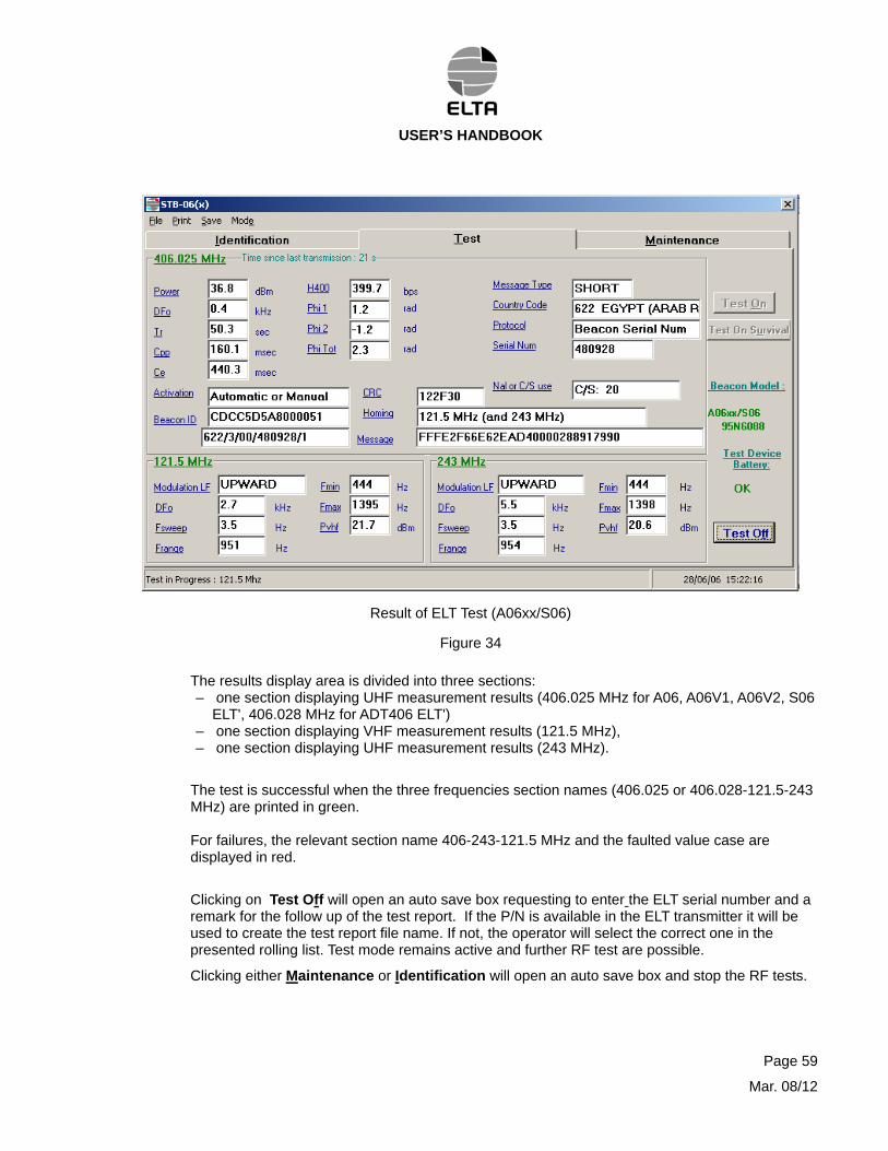
Result of ELT Test (A06xx/S06)
Figure 34
The results display area is divided into three sections: – one section displaying UHF measurement results (406.025 MHz for A06, A06V1, A06V2, S06
ELT', 406.028 MHz for ADT406 ELT') – one section displaying VHF measurement results (121.5 MHz), – one section displaying UHF measurement results (243 MHz).
The test is successful when the three frequencies section names (406.025 or 406.028-121.5-243 MHz) are printed in green. For failures, the relevant section name 406-243-121.5 MHz and the faulted value case are displayed in red.
Clicking on Test Off will open an auto save box requesting to enter the ELT serial number and a remark for the follow up of the test report. If the P/N is available in the ELT transmitter it will be used to create the test report file name. If not, the operator will select the correct one in the presented rolling list. Test mode remains active and further RF test are possible.
Clicking either Maintenance or Identification will open an auto save box and stop the RF tests.
Page 59
Mar. 08/12
USER’S HANDBOOK
- Display of UHF measurement results (406.028 MHz for ADT406 ELT, 406.025 MHz for A06, A06V2 and S06)
The test bench measures the following UHF data:
UHF power expressed in dBm, frequency deviation (DFo = F ELT – (406.028 MHz for ADT406 ELT, 406.025 MHz for A06 , A06V2 and S06) expressed in kHz, UHF transmission recurrence time (Tr) expressed in seconds, pure carrier pulse duration (Cpp) expressed in milliseconds, UHF transmission time (Ce) expressed in milliseconds, message digital pulse rate (H400) expressed in Hz, positive (Phi1), negative (Phi2) and total phase excursions (PhiTot) expressed in radian, the ELT message is summarized in the "ELT Identifier" box.
- Display of the VHF measurement results (121.5 MHz)
The test bench measures the following VHF data :
upward or downward amplitude modulation direction (Modulation LF), frequency deviation (DFo = F ELT - 121.5 MHz) expressed in kHz, amplitude modulation frequency sweep repetition rate (Fsweep) expressed in Hz, amplitude modulation minimum frequency (Fmin) expressed in Hz, amplitude modulation range frequency (Frange) expressed in Hz, amplitude modulation maximum frequency (Fmax) expressed in Hz, peak power of the 121.5 MHz transmitter (Pvhf) expressed in dBm.
- Display of the UHF measurement results (243 MHz)
The test bench measures the following VHF data:
upward or downward amplitude modulation direction (Modulation LF), frequency deviation (DFo= F ELT - 243 MHz) expressed in kHz, amplitude modulation frequency sweep repetition rate (Fsweep) expressed in Hz, amplitude modulation minimum frequency (Fmin) expressed in Hz, amplitude modulation range frequency (Frange) expressed in Hz, amplitude modulation maximum frequency (Fmax) expressed in Hz, peak power of the 243 MHz transmitter (Pvhf) expressed in dBm.
Page 60
Mar. 08/12
USER’S HANDBOOK
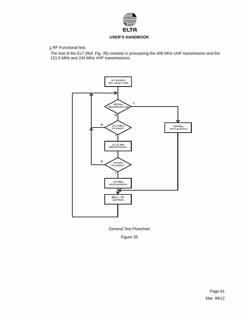
1 RF Functional test
The test of the ELT (Ref. Fig. 35) consists in processing the 406 MHz UHF transmission and the 121.5 MHz and 243 MHz VHF transmissions.
General Test Flowchart
Figure 35
Page 61
Mar. 08/12
USER’S HANDBOOK
a UHF transmission test (Ref. Fig. 36)
UHF FREQUENCY MEASUREMENT
UHF POWER MEASUREMENT
MODULATION FREQUENCY
MEASUREMENT
MESSAGE DEMODULATION
TR, CE, CPP PROCESSING
406 MHz PROCESSING
406 MHz UHF Signal Processing Flowchart
Figure 36
- First UHF transmission screen
The UHF measurements are made every 50 seconds. The measurement results are displayed at the same rate as the measurements are made and a decision is displayed in the 406.028 MHz for ADT406 ELT or 406.025 MHz for A06xx and S06 part.
The UHF transmissions recurrence time is measured on two UHF transmissions. At the beginning the UHF test always is negative (UHF Neg). The measurement concerned is not displayed.
- Second UHF measurement screen
After the second UHF transmission, the recurrence time (Tr) test must be correct.
Page 62
Mar. 08/12
USER’S HANDBOOK
b VHF transmission Test (Ref. Fig. 37)
The VHF measurements are made at 3 seconds intervals. The measurement results are displayed at the same rate as the measurements are made and a decision is displayed in the 121.5 MHz and 243 MHz parts.
VHF Signal Processing Flowchart
Figure 37
Page 63
Mar. 08/12
USER’S HANDBOOK
2 Test specification and interpreting the results
a Test specification
The performances must meet the specifications described in the following paragraphs. Two types of measurements are made: – measurements on the UHF channel (406.025 or 406.028 MHz), – measurements on the VHF/UHF channels (121.5 and 243 MHz). The display resolution is the last decimal displayed.
b 406.025 or 406.028 MHz channel
- Power measurement (PUHF)
ELT specification : +37 dBm ± 2 dBm. The coaxial input is protected up to +43 dBm in pulsed mode.
- Carrier frequency measurement (DFo)
ELT specification : 406.025 MHz ± 2 kHz or 406.028 MHz ± 1 kHz
- Transmissions recurrence time measurement (Tr)
ELT specification : 50 s ± 5% (± 2.5 s).
- Pure carrier pulse measurement (Cpp)
ELT specification : 160 ms ± 1% (± 1.6 ms).
- Transmission time measurement (CE)
ELT specification : Short message 440 ms ± 1% (± 4.4 ms), Long message 520 ms ± 1% (± 5.2 ms).
- Digital pulse rate measurement (H400)
ELT specification : 400 Hz ± 1% (± 4 Hz).
Page 64
Mar. 08/12
USER’S HANDBOOK
- Complete message decoding (Ref. Fig. 31)
Display of raw data. Check of the message structure: .. preamble, .. synchronization, .. identification, .. error correcting code.
Message decoding and display. Display of the optional long message (raw data).
- Check of the PM modulation index (Phi1, Phi2)
Phi1 = positive phase excursion (+ 1.1 rd). Phi2 = negative phase excursion (- 1.1 rd). ELT specification : ± 1.1 rd ± 0.1 rd.
c 121.5 MHz channel
- Carrier frequency measurement (DFo)
ELT specification : 121.5 MHz ± 6.075 kHz.
- Amplitude Modulation (AM) check
ELT specification :
.. AM frequency sweep direction : upward or downward. .. AM sweep frequency : between 2 Hz and 4 Hz (Fsweep), .. AM minimum frequency : 300 Hz (Fmin), .. AM maximum frequency : 1600 Hz (Fmax), .. AM minimum range : 700 Hz (DF),
- Power measurement (Pvhf)
ELT specification : +19 dBm +24 dBm. The coaxial input is protected up to +25 dBm in permanent mode.
Page 65
Mar. 08/12
USER’S HANDBOOK
d 243 MHz channel
- Carrier frequency measurement (DFo)
ELT specification : 243 MHz ± 12.150 kHz.
- Amplitude Modulation (AM) check
ELT specification :
.. AM frequency sweep direction : upward or downward. .. AM sweep frequency : between 2 Hz and 4 Hz (Fsweep), .. AM minimum frequency : 300 Hz (Fmin), .. AM maximum frequency : 1600 Hz (Fmax), .. AM minimum range : 700 Hz (DF),
- Power measurement (Pvhf)
ELT specification : +19 dBm +24 dBm. the coaxial input is protected up to +25 dBm in permanent mode.
3 Interpreting the results
The tests are : – satisfactory when the decision displayed on the screen are in green (Title boxes) – and unsatisfactory when the decision displayed on the screen are in red (Title boxes) The incorrect parameter(s) is (are) displayed in red. The ELT must then be returned to ELTA or to an approved agent.
Note: There is no filtering on the measurements (instantaneous). So non-permanent failure on one parameter will not impact on the ELT performances. If an error occurs, then wait for additionally transmissions measurements (keep in mind that 406.0xx MHz transmission occurs every 50 s). When there is a failure on one ELT parameter, this parameter remains displayed in red for quite all the consecutives measurements.
Page 66
Mar. 08/12
USER’S HANDBOOK
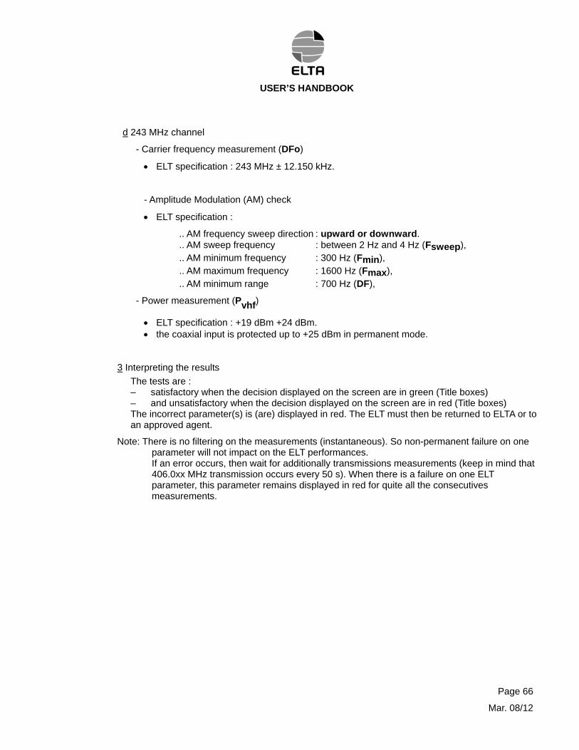
When an internal problem occurs with the Test Interface Device, the following screen (Ref. Fig. 38) is displayed requesting the operator to wait the next Cospas-Sarsat transmission.
This is not an ELT failure. This case may happen one or two times for 10 consecutive measurements.
Measurement Failure Screen
Figure 38
Page 67
Mar. 08/12
USER’S HANDBOOK
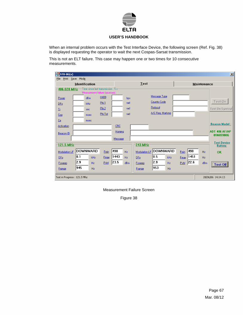
4 Reading Of Maintenance Tasks
On the test bench main menu screen Click Maintenance. The following maintenance screen (Ref. Fig. 39) is then displayed.
Note: Operator can select Maintenance in test or identification screens.
Maintenance Screen
Figure 39
Note: Maintenance information’s are not available for ADT406 S ELT.
Page 68
Mar. 08/12
USER’S HANDBOOK
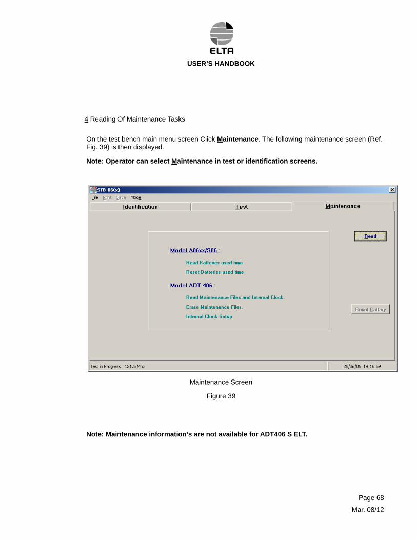
a A06xx and S06 ELT’
With these models the maintenance is limited to the “battery used time” counter that displays the cumulating time of ELT activation (per 15 minutes step).
- Read Function:
Click Read. The screen instructs the Operator to turn ON the ELT.
Turn ON the ELT. The loading of the maintenance information starts. When the loading is over the following screen (Ref. Fig. 40) is displayed and instructs the Operator to turn OFF the ELT.
Maintenance Tasks Screen for A06xx/S06
Figure 40
Page 69
Mar. 08/12
USER’S HANDBOOK
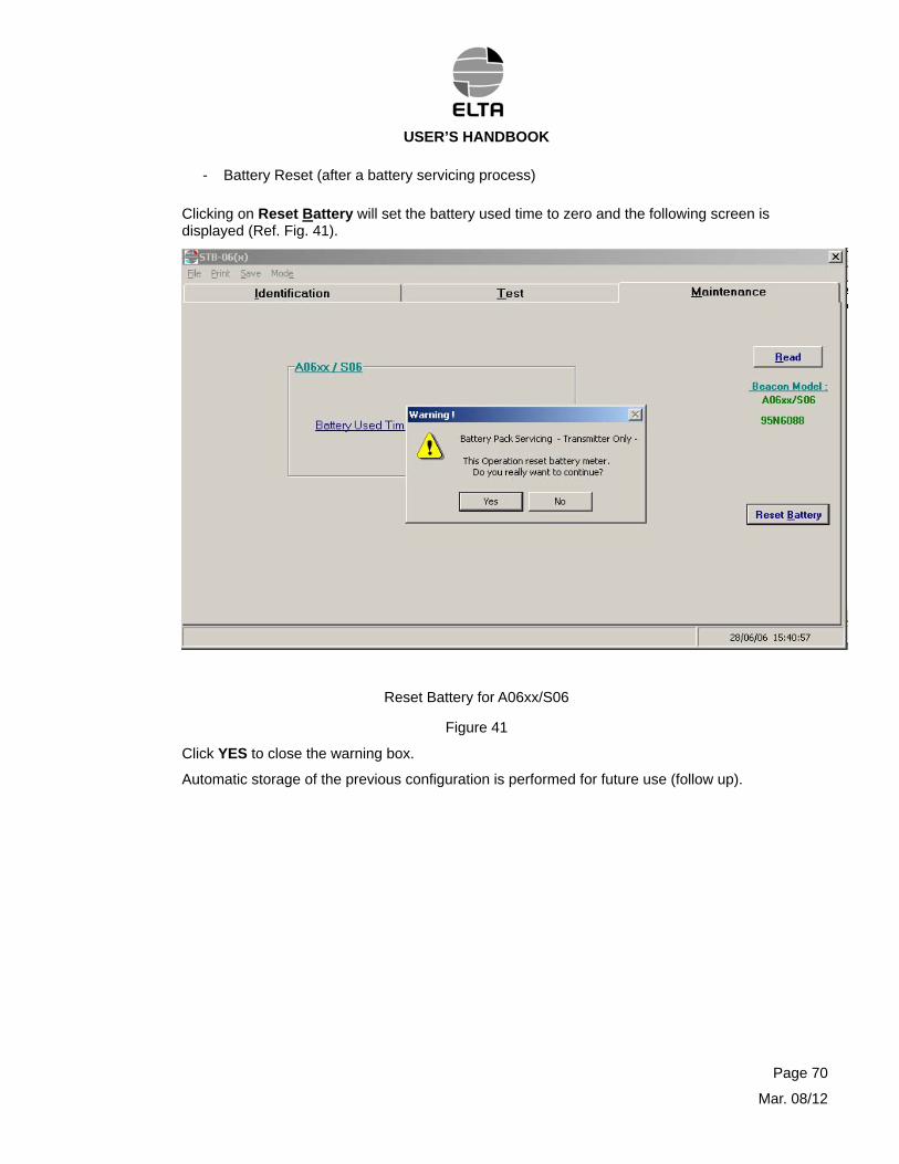
- Battery Reset (after a battery servicing process)
Clicking on Reset Battery will set the battery used time to zero and the following screen is displayed (Ref. Fig. 41).
Reset Battery for A06xx/S06
Figure 41
Click YES to close the warning box.
Automatic storage of the previous configuration is performed for future use (follow up).
Page 70
Mar. 08/12
USER’S HANDBOOK
Page 71
Mar. 08/12
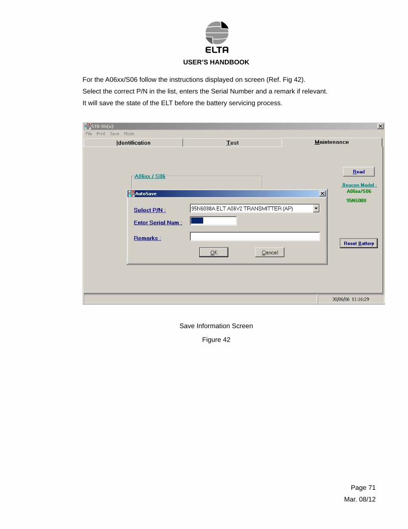
For the A06xx/S06 follow the instructions displayed on screen (Ref. Fig 42).
Select the correct P/N in the list, enters the Serial Number and a remark if relevant.
It will save the state of the ELT before the battery servicing process.
Save Information Screen
Figure 42
USER’S HANDBOOK
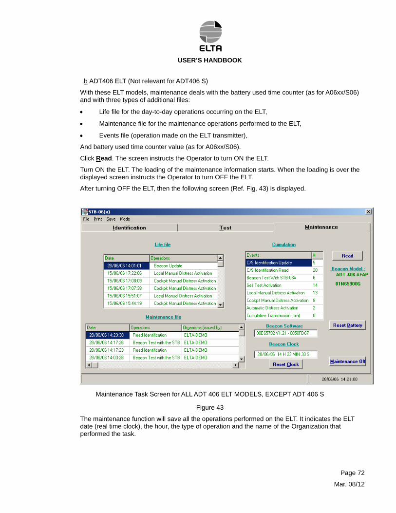
b ADT406 ELT (Not relevant for ADT406 S)
With these ELT models, maintenance deals with the battery used time counter (as for A06xx/S06) and with three types of additional files:
Life file for the day-to-day operations occurring on the ELT,
Maintenance file for the maintenance operations performed to the ELT,
Events file (operation made on the ELT transmitter),
And battery used time counter value (as for A06xx/S06).
Click Read. The screen instructs the Operator to turn ON the ELT.
Turn ON the ELT. The loading of the maintenance information starts. When the loading is over the displayed screen instructs the Operator to turn OFF the ELT.
After turning OFF the ELT, then the following screen (Ref. Fig. 43) is displayed.
Maintenance Task Screen for ALL ADT 406 ELT MODELS, EXCEPT ADT 406 S
Figure 43
The maintenance function will save all the operations performed on the ELT. It indicates the ELT date (real time clock), the hour, the type of operation and the name of the Organization that performed the task.
Page 72
Mar. 08/12
USER’S HANDBOOK
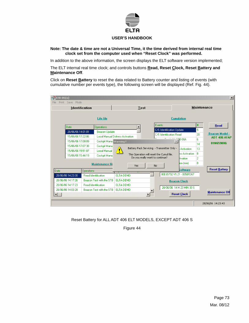
Note: The date & time are not a Universal Time, it the time derived from internal real time clock set from the computer used when “Reset Clock” was performed.
In addition to the above information, the screen displays the ELT software version implemented;
The ELT internal real time clock; and controls buttons Read, Reset Clock, Reset Battery and Maintenance Off.
Click on Reset Battery to reset the data related to Battery counter and listing of events (with cumulative number per events type), the following screen will be displayed (Ref. Fig. 44).
Reset Battery for ALL ADT 406 ELT MODELS, EXCEPT ADT 406 S
Figure 44
Page 73
Mar. 08/12
USER’S HANDBOOK
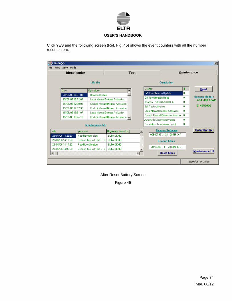
Click YES and the following screen (Ref. Fig. 45) shows the event counters with all the number reset to zero.
After Reset Battery Screen
Figure 45
Page 74
Mar. 08/12
USER’S HANDBOOK
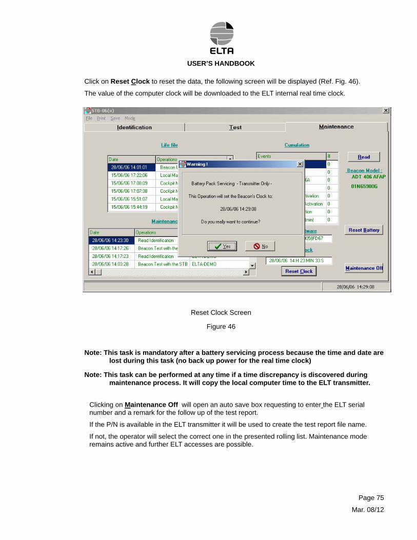
Click on Reset Clock to reset the data, the following screen will be displayed (Ref. Fig. 46).
The value of the computer clock will be downloaded to the ELT internal real time clock.
Reset Clock Screen
Figure 46
Note: This task is mandatory after a battery servicing process because the time and date are lost during this task (no back up power for the real time clock)
Note: This task can be performed at any time if a time discrepancy is discovered during maintenance process. It will copy the local computer time to the ELT transmitter.
Clicking on Maintenance Off will open an auto save box requesting to enter the ELT serial number and a remark for the follow up of the test report.
If the P/N is available in the ELT transmitter it will be used to create the test report file name.
If not, the operator will select the correct one in the presented rolling list. Maintenance mode remains active and further ELT accesses are possible.
Page 75
Mar. 08/12
USER’S HANDBOOK
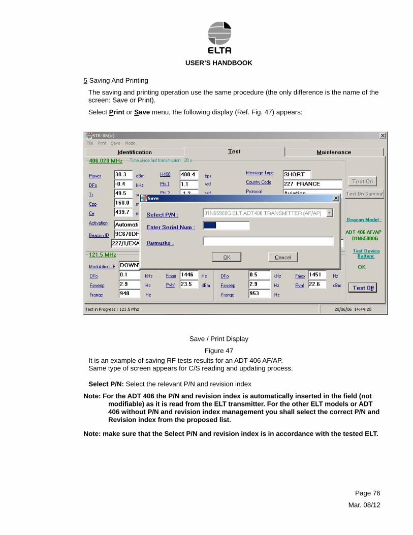
5 Saving And Printing
The saving and printing operation use the same procedure (the only difference is the name of the screen: Save or Print).
Select Print or Save menu, the following display (Ref. Fig. 47) appears:
Save / Print Display
Figure 47
It is an example of saving RF tests results for an ADT 406 AF/AP. Same type of screen appears for C/S reading and updating process. Select P/N: Select the relevant P/N and revision index
Note: For the ADT 406 the P/N and revision index is automatically inserted in the field (not modifiable) as it is read from the ELT transmitter. For the other ELT models or ADT 406 without P/N and revision index management you shall select the correct P/N and Revision index from the proposed list.
Note: make sure that the Select P/N and revision index is in accordance with the tested ELT.
Page 76
Mar. 08/12
USER’S HANDBOOK
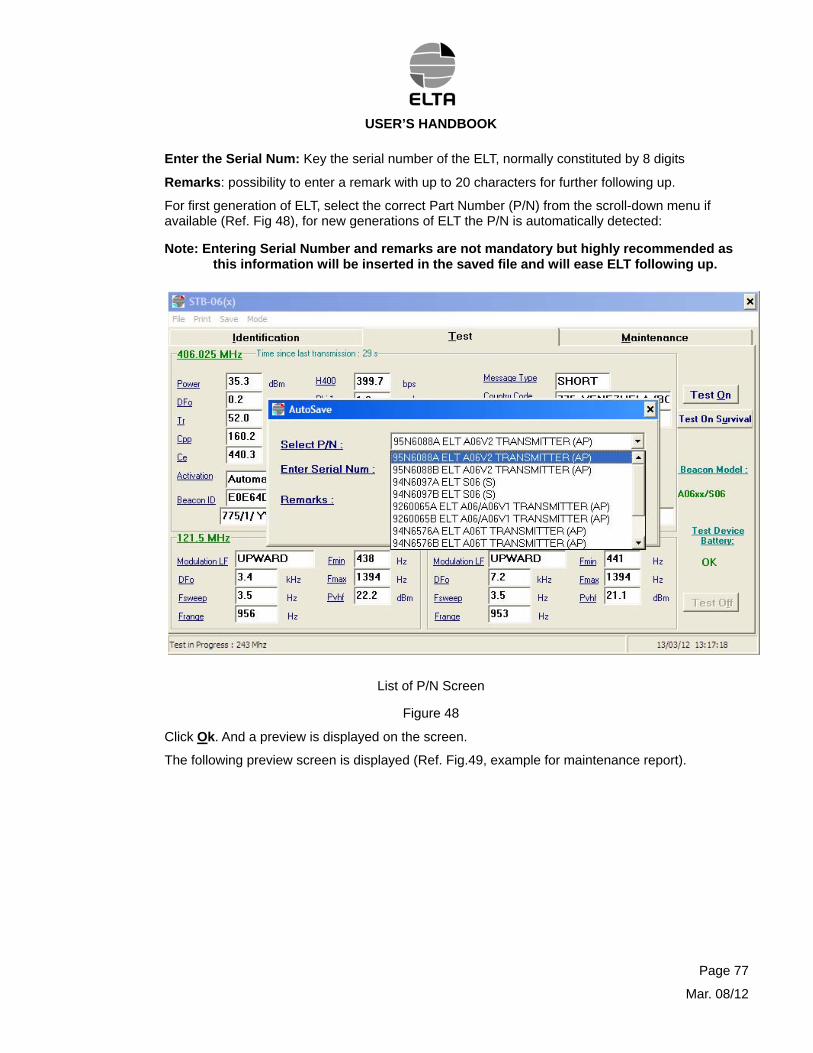
Enter the Serial Num: Key the serial number of the ELT, normally constituted by 8 digits
Remarks: possibility to enter a remark with up to 20 characters for further following up.
For first generation of ELT, select the correct Part Number (P/N) from the scroll-down menu if available (Ref. Fig 48), for new generations of ELT the P/N is automatically detected:
Note: Entering Serial Number and remarks are not mandatory but highly recommended as this information will be inserted in the saved file and will ease ELT following up.
List of P/N Screen
Figure 48
Click Ok. And a preview is displayed on the screen.
The following preview screen is displayed (Ref. Fig.49, example for maintenance report).
Page 77
Mar. 08/12
USER’S HANDBOOK
Printing and Saving Maintenance Screen - Figure 49
Page 78
Mar. 08/12
USER’S HANDBOOK
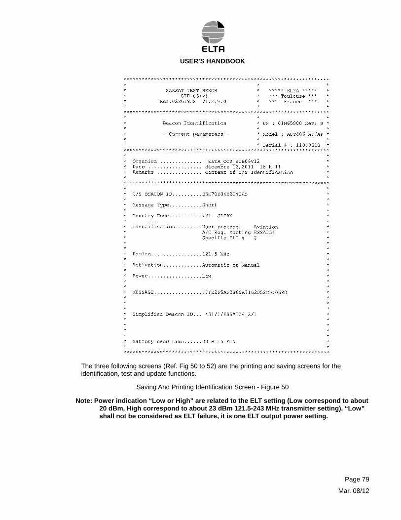
The three following screens (Ref. Fig 50 to 52) are the printing and saving screens for the identification, test and update functions.
Saving And Printing Identification Screen - Figure 50
Note: Power indication “Low or High” are related to the ELT setting (Low correspond to about 20 dBm, High correspond to about 23 dBm 121.5-243 MHz transmitter setting). “Low” shall not be considered as ELT failure, it is one ELT output power setting.
Page 79
Mar. 08/12
USER’S HANDBOOK
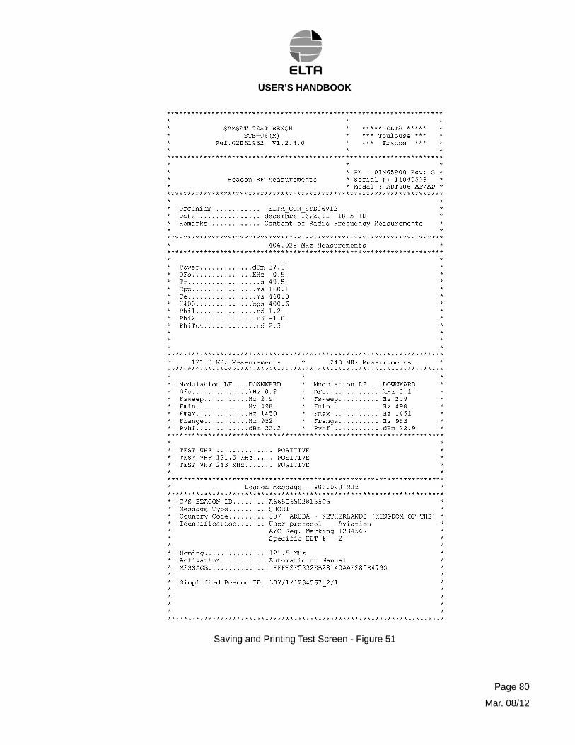
Saving and Printing Test Screen - Figure 51
Page 80
Mar. 08/12
USER’S HANDBOOK
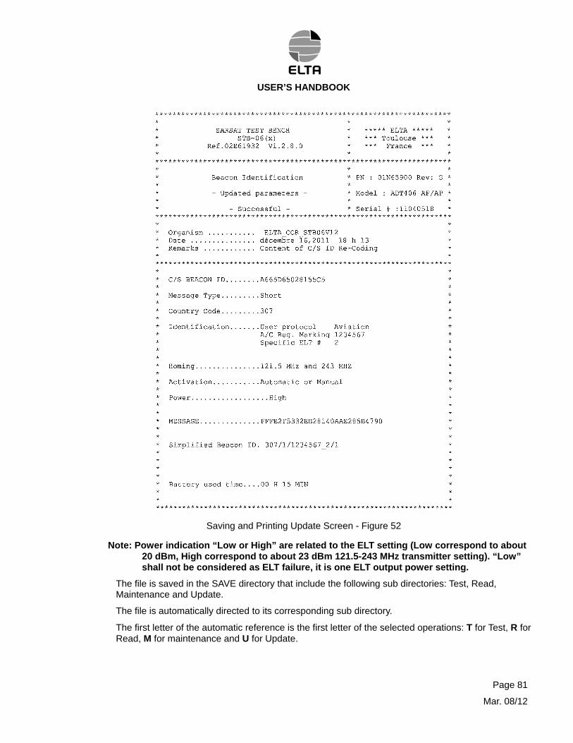
Saving and Printing Update Screen - Figure 52
Note: Power indication “Low or High” are related to the ELT setting (Low correspond to about 20 dBm, High correspond to about 23 dBm 121.5-243 MHz transmitter setting). “Low” shall not be considered as ELT failure, it is one ELT output power setting.
The file is saved in the SAVE directory that include the following sub directories: Test, Read, Maintenance and Update.
The file is automatically directed to its corresponding sub directory.
The first letter of the automatic reference is the first letter of the selected operations: T for Test, R for Read, M for maintenance and U for Update.
Page 81
Mar. 08/12
USER’S HANDBOOK
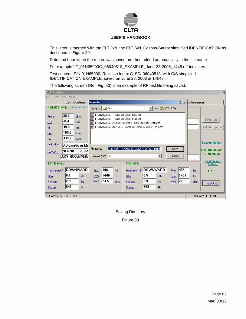
This letter is merged with the ELT P/N, the ELT S/N, Cospas-Sarsat simplified IDENTIFICATION as described in Figure 29.
Date and hour when the record was saved are then added automatically in the file name.
For example “ T_01N65900G_06040518_EXAMPLE_June-28-2006_1448.rtf” indicates:
Test content, P/N 01N65900, Revision Index G, S/N 06040518, with C/S simplified IDENTIFICATION EXAMPLE, saved on June 28, 2006 at 14h48’.
The following screen (Ref. Fig. 53) is an example of RF test file being saved.
Saving Directory
Figure 53
Page 82
Mar. 08/12
USER’S HANDBOOK
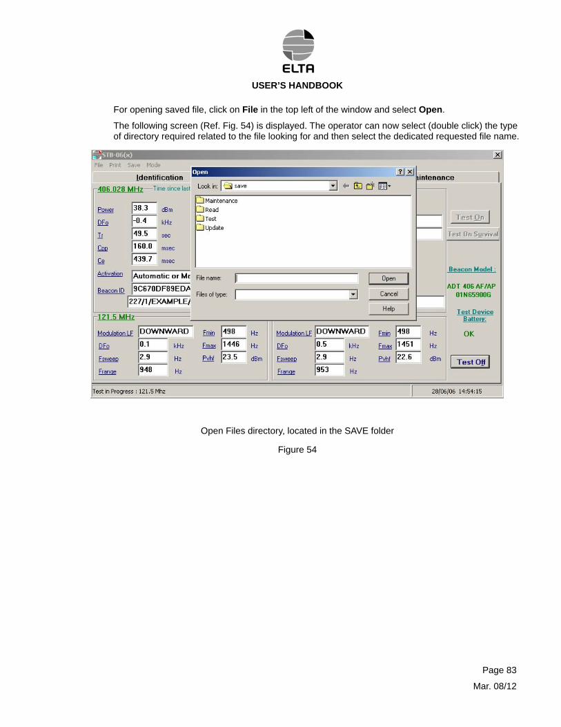
For opening saved file, click on File in the top left of the window and select Open.
The following screen (Ref. Fig. 54) is displayed. The operator can now select (double click) the type of directory required related to the file looking for and then select the dedicated requested file name.
Open Files directory, located in the SAVE folder
Figure 54
Page 83
Mar. 08/12
USER’S HANDBOOK
5. MAINTENANCE
The test bench does not require any special maintenance operation, care must simply be taken to ensure that the batteries are correctly charged (for STB-06-A only).
A. Calibration
The test bench must be checked (calibration verification) every two years in order to guarantee measurement reliability.
This task shall be performed by ELTA. A Calibration Certificate is issued by ELTA to release the test bench to service.
B. Spare parts list
The following spare parts are available in order to guarantee measurement reliability.
- Case and foam filling : 05N61329
- Test Interface Device battery : 94P7660
- RS232 cable between the Test Interface Device and portable computer : 94N6493
- USB/RS232 adapter for portable computer : 28946
- RF coaxial cable (50 ) with TNC/BNC adapter : 94N6460
- Programming cable for A06xx/S06 : 93N6222
- Programming cable for Programming Box (A06V2) : 96N9028
- Extension programming cable for A06V2 : 96N9029
- Programming cable for ADT 406(x) : 02N65746
- ADT programming cable 5 meters serial link extension : 02N66199
- RS 232 serial link for computer connection (STB-06-LA) : 95N6072
- International external power supply plug converter : 25323
- Dual external power supply socket : 27126
- Test Interface Device External Power Supply adapter : 24931
- Test Interface Device : 00N62873
- Portable computer, with disk drives : 05P62443
- CodADT tool : 05N62132
- User’s handbook STB 06 A/LA : 02E65745
- Remote unit simulator (for Prog. Box A06V2) : 99N9002
Contact ELTA to obtain these spare parts.
Page 84
Mar. 08/12
USER’S HANDBOOK
C. Fault locating
TYPE OF FAULT CORRECTION
All faults.
The charging light does not come on when connected to mains.
Measurements are not obtained.
The measurement are incorrect on all ELT’.
The measurement is incorrect on one ELT.
No measurement in UHF
CodADT tool Led indicator didn’t activate when turn on the switch
Reset and recharge the battery on the mains
Check the cables and that mains power is present
Check the cables and change ELT.
Check the cables.
Allow to warm up then measure again.
Reset the Test Interface Device (ON/OFF) and start up the STB_06 software again.
Switch the 9V battery of CodADT tool (“PP3” or “6LR61” type)
If after having corrected fault(s) as describe above, the fault(s) persist(s), replace the test bench or the ELT under test, depending on the type of fault detected.
6. REPLACEMENT OF THE BATTERY
A. Computer
(1)Precaution to take before replacement
Normally, the battery does not have to be removed; simply connect the mains and perform a full recharged process (about 5 hours) to obtain autonomous operation for about 2 hours.
(2)Replacing the battery
Proceed as follows to replace the battery (Ref. Fig 4):
- Turn OFF the computer and only turn it ON again once the battery has been charged.
- Disconnect all connections and turn over the computer,
- Press on the battery release mechanism,
- Remove the battery by pulling the battery pack,
- Installed the new battery pack and secure it (click),
- Connect all the removed cables,
- Connect power supplies to mains and recharge the battery pack (a full charging cycle is recommended),
- Turn the computer power back to ON.
Page 85
Mar. 08/12
USER’S HANDBOOK
CAUTION: BE CAREFUL WITH OLD BATTERY. DO NOT PUNCTURE NOR PUT THEM IN A FIRE NOR TRY TO CHARGE NOR DISASSEMBLE THEM.THEY COULD SPLIT AND/OR EXPLODE. DANGEROUS SUBSTANCE MAY LEAK. DO NOT THROW THEM AWAY. FOLLOW THE INSTRUCTIONS GIVEN BY THE BATTERY MANUFACTURER AND FOLLOW LOCAL DISCARDING RULES
B. CodADT tool
- Move the switch to OFF,
- Disconnect the CodADT tool from test interface device,
- Open the battery compartment on the side of the CodADT tool by pulling with a screwdriver,
- Remove the old battery and place the new with keeping the good polarity
C. Test Interface Device (Ref. Fig 55):
- Disconnect the Test Interface Device connectors.
- Open the plastic box using a screwdriver blade inserted in the holes on the sides of the box.
- Disconnect the two battery wires (3) from the terminal strip located on the Test Interface Device board (1), using a screwdriver.
CAUTION: DO NOT SHORT CIRCUIT THE TWO DISCONNECTED WIRES.
- Remove the battery (3) from the bottom part of the box.
- Fit the new battery (3) in the box.
- Re connect the two wires to the terminal strip (2).
CAUTION: DO NOT SHORT CIRCUIT THE TWO WIRES WHEN MAKING THE CONNECTION.
MAKE SURE THAT THE TWO WIRES ARE CONNECTED IN THE RIGHT DIRECTION.
- Close the box.
- Charge the unit.
Page 86
Mar. 08/12
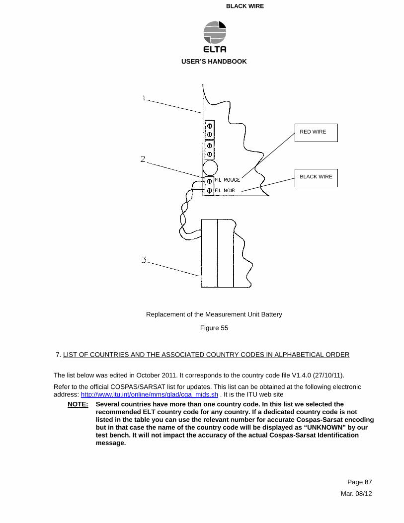
RED WIREBLACK WIRE
USER’S HANDBOOK
Page 87
Mar. 08/12
RED WIRE
BLACK WIRE
Replacement of the Measurement Unit Battery
Figure 55
7. LIST OF COUNTRIES AND THE ASSOCIATED COUNTRY CODES IN ALPHABETICAL ORDER
The list below was edited in October 2011. It corresponds to the country code file V1.4.0 (27/10/11).
Refer to the official COSPAS/SARSAT list for updates. This list can be obtained at the following electronic address: http://www.itu.int/online/mms/glad/cga_mids.sh . It is the ITU web site
NOTE: Several countries have more than one country code. In this list we selected the recommended ELT country code for any country. If a dedicated country code is not listed in the table you can use the relevant number for accurate Cospas-Sarsat encoding but in that case the name of the country code will be displayed as “UNKNOWN” by our test bench. It will not impact the accuracy of the actual Cospas-Sarsat Identification message.
USER’S HANDBOOK
Country code file V1.4.0 (27/oct/11)
0355 -
0356 -
0357 -
0501 Adelie Land
0401 Afghanistan
0303 Alaska (State of) - United States of America
0201 Albania (Republic of)
0605 Algeria (People's Democratic Republic of)
0559 American Samoa - United States of America
0202 Andorra (Principality of)
0603 Angola (Republic of)
0301 Anguilla - United Kingdom of Great Britain and Northern Ireland
0304 Antigua and Barbuda
0701 Argentine Republic
0216 Armenia (Republic of)
0307 Aruba - Netherlands (Kingdom of the)
0608 Ascension Island - United Kingdom of Great Britain and Northern Ireland
0503 Australia
0203 Austria
0423 Azerbaijani Republic
0204 Azores
0309 Bahamas (Commonwealth of the)
0408 Bahrain (Kingdom of)
0405 Bangladesh (People's Republic of)
0314 Barbados
0206 Belarus (Republic of)
0205 Belgium
0312 Belize
0610 Benin (Republic of)
0310 Bermuda - United Kingdom of Great Britain and Northern Ireland
0410 Bhutan (Kingdom of)
0720 Bolivia (Plurinational State of)
0478 Bosnia and Herzegovina
0611 Botswana (Republic of)
0710 Brazil (Federative Republic of)
0378 British Virgin Islands - United Kingdom of Great Britain and Northern Ireland
0508 Brunei Darussalam
0207 Bulgaria (Republic of)
0633 Burkina Faso
0609 Burundi (Republic of)
0514 Cambodia (Kingdom of)
0613 Cameroon (Republic of)
0316 Canada
0617 Cape Verde (Republic of)
0319 Cayman Islands - United Kingdom of Great Britain and Northern Ireland
0612 Central African Republic
0670 Chad (Republic of)
0725 Chile
0412 China (People's Republic of)
0516 Christmas Island (Indian Ocean) - Australia
0523 Cocos (Keeling) Islands - Australia
0730 Colombia (Republic of)
0616 Comoros (Union of the)
0615 Congo (Republic of the)
0518 Cook Islands - New Zealand
0321 Costa Rica
0619 Côte d'Ivoire (Republic of)
0238 Croatia (Republic of)
0618 Crozet Archipelago - France
0323 Cuba
Page 88
Mar. 08/12
USER’S HANDBOOK
0210 Cyprus (Republic of)
0270 Czech Republic
0445 Democratic People's Republic of Korea
0676 Democratic Republic of the Congo
0219 Denmark
0621 Djibouti (Republic of)
0325 Dominica (Commonwealth of)
0327 Dominican Republic
0735 Ecuador
0622 Egypt (Arab Republic of)
0359 El Salvador (Republic of)
0631 Equatorial Guinea (Republic of)
0625 Eritrea
0276 Estonia (Republic of)
0624 Ethiopia (Federal Democratic Republic of)
0740 Falkland Islands (Malvinas) - United Kingdom of Great Britain and Northern Ireland
0231 Faroe Islands - Denmark
0520 Fiji (Republic of)
0230 Finland
0227 France
0546 French Polynesia - France
0626 Gabonese Republic
0629 Gambia (Republic of the)
0213 Georgia
0218 Germany (Federal Republic of)
0627 Ghana
0236 Gibraltar - United Kingdom of Great Britain and Northern Ireland
0237 Greece
0331 Greenland - Denmark
0330 Grenada
0329 Guadeloupe (French Department of) - France
0332 Guatemala (Republic of)
0745 Guiana (French Department of) - France
0632 Guinea (Republic of)
0630 Guinea-Bissau (Republic of)
0750 Guyana
0336 Haiti (Republic of)
0334 Honduras (Republic of)
0477 Hong Kong (Special Administrative Region of China) - China (People's Republic of)
0243 Hungary (Republic of)
0251 Iceland
0419 India (Republic of)
0525 Indonesia (Republic of)
0422 Iran (Islamic Republic of)
0425 Iraq (Republic of)
0250 Ireland
0428 Israel (State of)
0247 Italy
0339 Jamaica
0431 Japan
0438 Jordan (Hashemite Kingdom of)
0436 Kazakhstan (Republic of)
0634 Kenya (Republic of)
0635 Kerguelen Islands - France
0529 Kiribati (Republic of)
0440 Korea (Republic of)
0447 Kuwait (State of)
0451 Kyrgyz Republic
0531 Lao People's Democratic Republic
0275 Latvia (Republic of)
0450 Lebanon
0644 Lesotho (Kingdom of)
0636 Liberia (Republic of)
Page 89
Mar. 08/12
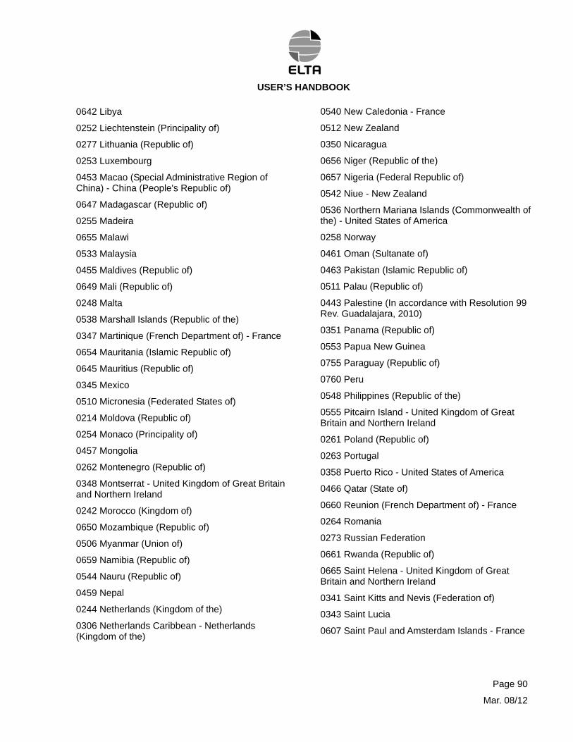
USER’S HANDBOOK
0642 Libya
0252 Liechtenstein (Principality of)
0277 Lithuania (Republic of)
0253 Luxembourg
0453 Macao (Special Administrative Region of China) - China (People's Republic of)
0647 Madagascar (Republic of)
0255 Madeira
0655 Malawi
0533 Malaysia
0455 Maldives (Republic of)
0649 Mali (Republic of)
0248 Malta
0538 Marshall Islands (Republic of the)
0347 Martinique (French Department of) - France
0654 Mauritania (Islamic Republic of)
0645 Mauritius (Republic of)
0345 Mexico
0510 Micronesia (Federated States of)
0214 Moldova (Republic of)
0254 Monaco (Principality of)
0457 Mongolia
0262 Montenegro (Republic of)
0348 Montserrat - United Kingdom of Great Britain and Northern Ireland
0242 Morocco (Kingdom of)
0650 Mozambique (Republic of)
0506 Myanmar (Union of)
0659 Namibia (Republic of)
0544 Nauru (Republic of)
0459 Nepal
0244 Netherlands (Kingdom of the)
0306 Netherlands Caribbean - Netherlands (Kingdom of the)
0540 New Caledonia - France
0512 New Zealand
0350 Nicaragua
0656 Niger (Republic of the)
0657 Nigeria (Federal Republic of)
0542 Niue - New Zealand
0536 Northern Mariana Islands (Commonwealth of the) - United States of America
0258 Norway
0461 Oman (Sultanate of)
0463 Pakistan (Islamic Republic of)
0511 Palau (Republic of)
0443 Palestine (In accordance with Resolution 99 Rev. Guadalajara, 2010)
0351 Panama (Republic of)
0553 Papua New Guinea
0755 Paraguay (Republic of)
0760 Peru
0548 Philippines (Republic of the)
0555 Pitcairn Island - United Kingdom of Great Britain and Northern Ireland
0261 Poland (Republic of)
0263 Portugal
0358 Puerto Rico - United States of America
0466 Qatar (State of)
0660 Reunion (French Department of) - France
0264 Romania
0273 Russian Federation
0661 Rwanda (Republic of)
0665 Saint Helena - United Kingdom of Great Britain and Northern Ireland
0341 Saint Kitts and Nevis (Federation of)
0343 Saint Lucia
0607 Saint Paul and Amsterdam Islands - France
Page 90
Mar. 08/12
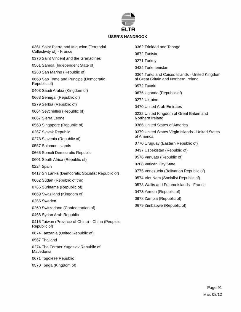
USER’S HANDBOOK
Page 91
Mar. 08/12
0361 Saint Pierre and Miquelon (Territorial Collectivity of) - France
0376 Saint Vincent and the Grenadines
0561 Samoa (Independent State of)
0268 San Marino (Republic of)
0668 Sao Tome and Principe (Democratic Republic of)
0403 Saudi Arabia (Kingdom of)
0663 Senegal (Republic of)
0279 Serbia (Republic of)
0664 Seychelles (Republic of)
0667 Sierra Leone
0563 Singapore (Republic of)
0267 Slovak Republic
0278 Slovenia (Republic of)
0557 Solomon Islands
0666 Somali Democratic Republic
0601 South Africa (Republic of)
0224 Spain
0417 Sri Lanka (Democratic Socialist Republic of)
0662 Sudan (Republic of the)
0765 Suriname (Republic of)
0669 Swaziland (Kingdom of)
0265 Sweden
0269 Switzerland (Confederation of)
0468 Syrian Arab Republic
0416 Taiwan (Province of China) - China (People's Republic of)
0674 Tanzania (United Republic of)
0567 Thailand
0274 The Former Yugoslav Republic of Macedonia
0671 Togolese Republic
0570 Tonga (Kingdom of)
0362 Trinidad and Tobago
0672 Tunisia
0271 Turkey
0434 Turkmenistan
0364 Turks and Caicos Islands - United Kingdom of Great Britain and Northern Ireland
0572 Tuvalu
0675 Uganda (Republic of)
0272 Ukraine
0470 United Arab Emirates
0232 United Kingdom of Great Britain and Northern Ireland
0366 United States of America
0379 United States Virgin Islands - United States of America
0770 Uruguay (Eastern Republic of)
0437 Uzbekistan (Republic of)
0576 Vanuatu (Republic of)
0208 Vatican City State
0775 Venezuela (Bolivarian Republic of)
0574 Viet Nam (Socialist Republic of)
0578 Wallis and Futuna Islands - France
0473 Yemen (Republic of)
0678 Zambia (Republic of)
0679 Zimbabwe (Republic of)


![Lignes directrices pour l’établissement d’un système ...«allotissement» et «assignation» respectivement par les articles 1.17 et 1.18 du RR. [1] On entend par assignation](https://img.pdfslide.net/doc/110x75/5f4e855046e2cf2fd1308ac1/lignes-directrices-pour-latablissement-daun-systme-allotissement.jpg)