Embed Size (px)
Citation preview
Kimmel Cerke Associates, Ltd.
O R I G I N A L L Y P U B L I S H E D A SChapter 1EMI, noise, andinterference— adifferent game
Chapter 2EMI regulations: why,where, and what dothey mean
Chapter 3BSD as an EMI prob-lem: how to prevent, fix
Chapter 4Power disturbancesas EMI problems
Chapter 5Radio-frequencyinterference: whycomputers hate radiotransmitters
Chapter 6Emissions: why radiosand televisions hatecomputers
Chapter 7Circuit components:where the rubbermeets the road
Chapter 8Bulletproof circuitboards against EMI
Chapter 9Shielding for EMIcontrol...how to doit right
Chapter 10Cables andconnectors: how tostop EMI leaks
Chapter 11Power-supply designfor EMI: filters aren'tenough
Chapter 12Grounding: facts andfallacies
Chapter 13EMI testing: don'twait
Chapter 14Troubleshooting
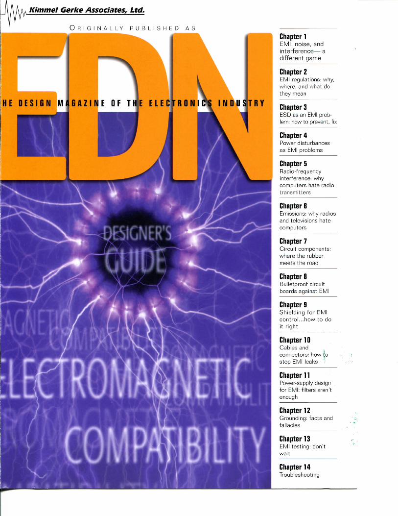
EDNThe Designer's Guide to
Electromagnetic Compatibility— Daryl Gerke, PE and Bill Kimmel, PE,
Kimmel Gerke Associates Ltd
CHAPTER 1EMI, noise, and interference—a different game 3
CHAPTER 2EMI regulations: why, where, and what they mean 9
CHAPTER 3ESD as an EMI problem: how to prevent and fix 15
CHAPTER 4Power disturbances as EMI problems 23
CHAPTER 5Radio-frequency interference: why computers hateradio transmitters 30
CHAPTER 6Emissions: why radios and televisions hate computers 35
CHAPTER 7Circuit components: where the rubber meets the road 42
CHAPTER 8Bulletproof circuit boards against EMI 49
CHAPTER 9Shielding for EMI control...how to do it right 58
CHAPTER 10Cables and connectors: how to stop the EMI leaks 65
CHAPTER 11Power supply design for EMI: filters aren't enough 72
CHAPTER 12Grounding: facts and fallacies 79
CHAPTER 13EMI testing: if you wait until the end, it's too late 86
CHAPTER 14Troubleshooting: EMI in the trenches 94
Copyright © 2005 by Kimmel Gerke Associates, Ltd.
www.emiguru.com KGA 1
EMI/EMC GiiiriB Jntrndurtinn
Why did we updatethis series?
I N 1994, WHEN THE FIRST EDITION of the EDN Designer's Guide to Electromagnetic Compatibility
appeared, enforcement of the mandatory European Union (EU) EMI/EMC (electromagnetic
interference and compatibility) rules was still two years away. As such, many designers were
just beginning to worry about EMI problems. Now, seven years later, the same old EMI problems
are still with us, and some new ones have emerged as well.
Thus, when EDN asked us to updatethis popular guide, we readily agreed. Asconsulting engineers specializing inEMI/EMC issues, we continue to see alot of misunderstanding and miscon-ceptions about EMI. Between us, weshare almost 70 years of collective EMIexperience; for the past 14 years, wehave dealt with nothing else but EMI. Inspite of all our efforts (consulting, training,and publishing), we still see a lot of thesame problems over and over again.Many of these problems could be avoidedat little or no cost with simple designtechniques.
If you have one of the original copiesof the guide (they must be collectors'items by now), you'll recognize some ofthe same material. After all, the under-lying principles and physics of EMChaven't changed. We have, however,updated time-sensitive information(such as regulations) and incorporateda number of new EMC concepts andideas. The biggest improvements are thetotally new chapter on components, thecompletely revised chapter on pcboards, and a dedicated chapter onemissions (previously covered in thechapter on RF interference).
We hope you enjoy our efforts andfind them useful. Updating this guidehas been a lot of work, but we saw it asour chance to give something back toour profession. As with the original,we've taken a nontraditional approachto EMC. You'll see very few equations(no integrals or partial differentialequations) or arcane theories, and you'llfind no excruciating details on EMCrules and regulations. Rather, we shareour practical nuts-and-bolts ideas andinsights, aimed at helping you identify,prevent, and fix EMI problems as youdesign your equipment and systems.
When we wrote the original guide, wewere inspired by Bob Pease and hisclassic EDN series, TroubleshootingAnalog Circuits. Reading his articles wasalmost like having a conversation with afriend. We've tried to capture that samefeeling again. In fact, as we sit down atthe keyboard, we often imagine thatwe're talking with a young, frustratedengineer that has just encountered his orher first big EMI problem. But we hopeour insights also help those older duffers(like us) who are also often tormentedby EMI.
We thank those who have graciously
shared their time and EMI wisdom withus. It's impossible to name them all, butyou know who you are. To our colleaguesin the IEEE EMC Society, we owe you aspecial debt of gratitude. (If you are at allinterested in EMI/EMC issues, this is theprofessional organization to join.) Aspecial word of thanks to the editorialstaff at EDN, who once again patientlysupported this project. We have enjoyedreading EDN for years, and we havecertainly benefited from the sharedknowledge of the magazine's manycontributors.
Finally, we owe special thanks to ourfamilies for supporting our dream ofhaving our own consulting practice, ascrazy and interesting as it has been.Once again, we dedicate this series toour wives, Mary Lou Gerke andSharon Kimmel.
Daryl Gerke, PE, and William Kimmel, PEKimmel Gerke Associates Ltd.
Mesa, AZ • South St. Paul, MN
2 KGA www.emiguru. com
EMI/EMC Guide Chapter 1
EMI, noise,and interferencea different gameWELCOME TO THE UPDATED VERSION of the EDNDesigner's
Guide to Electromagnetic Compatibility. Since theoriginal issue was published in 1994, there have been a
lot of changes in the world of electronics, and many of those affectthe EMI/EMC (electromagnetic interference and compatibility)of your equipment and designs. At the same time, underlyingprinciples remain the same. This update attempts to combine thebest of the old and the new regarding design tips and techniquesfor EMC. Welcome aboard!
There are two types of design engineers:those who have had EMI problems, andthose who will. Regardless of whichcategory you're in, you probably feel thatEMI is a black art that defies logic, science,and perhaps even reason.
But like most technical problems,there is an underlying sense of order.There are rules and strategies— evenregulations, thanks to governmentintervention. It's really just a game, andwith some fundamental knowledge andinsight, you can learn the EMI game.With enough time and practice, you caneven become a pretty good player.
That's what this guide is all about:how to play the EMI game. It's a gamewe've played collectively for over 70 yearsas full-time consulting engineers thatspecialize in solving EMI problems. No,we're not EMI test engineers—we'redesign engineers like you, and our focusis on identifying, preventing, and fixingEMI problems at the equipment andsystems levels. Because of that focus,we've seen some patterns emerge that canhelp you understand and solve EMI
design problems. We've also encounteredsome myths and misunderstandings thatonly confuse the issues. We now hope toshare some of that hard-earned knowledgewith you, our colleagues in design.
This guide is a tutorial, not an in-depthtreatise on EMI. It's aimed at the designer(not the EMI expert), and it's about EMIdesign issues (not testing or exotictheories.) It covers the EMI game in 14articles. Each chapter is written to standalone, so if you have aspecific problem, youcan just read theappropriate chapter.The first six chaptersdeal with the mostcommon EMI prob-lems and their impacton designs; the secondsix focus on EMIdesign solutions at theboard, box, and sys-tems levels; and thelast two deal with test-ing and troubleshoot-ing EMI problems.
One caution: We can't make you a20-year EMI expert in 14 easy lessons,but we hope we can help you betterunderstand the EMI game and how toplay to win.
WHAT IS THIS THING CALLED EMI, ANYWAY?If you're going to play any game, you
need to know the rules. And you need toknow the underlying philosophy of thegame.
Let's start at the beginning with a fewsimple definitions. Although some ofthese terms may be used differently byothers, we'll present how they're used inthe EMI business.
EMI, or electromagnetic interference,is a problem. Simply stated, a piece ofelectronic equipment isn't working like itshould, due to unwanted electrical energyin the wrong place at the wrong timedoing the wrong things. EMI is a kind ofelectronic juvenile delinquent.
EMC, or electromagnetic compatibility,is the solution. Simply stated, a piece ofelectronic equipment works like itshould in its intended electromagnetic
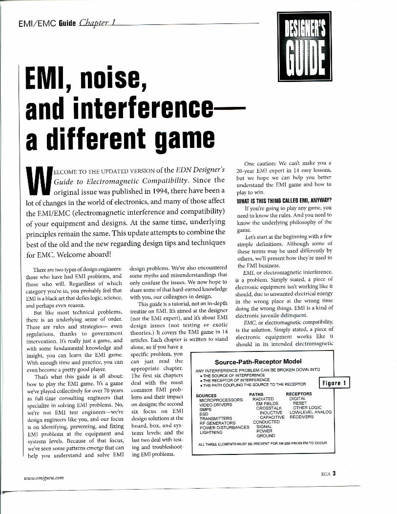
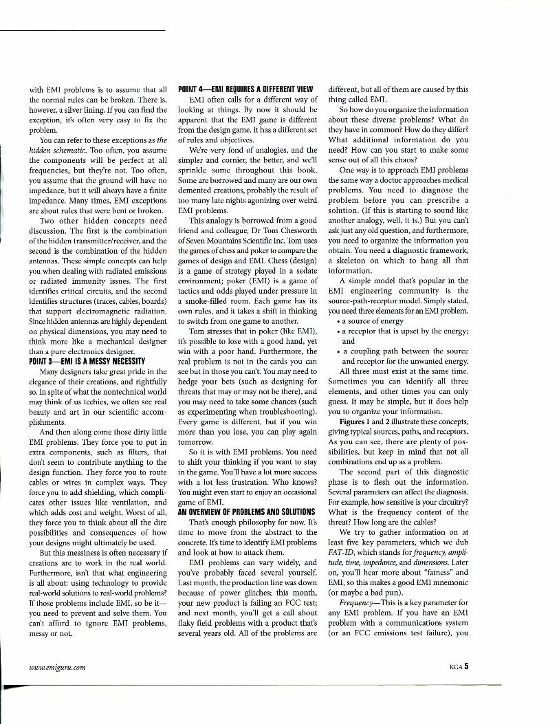
Source-Path-Receptor ModelANY INTERFERENCE PROBLEM CAN BE BROKEN DOWN INTO• THE SOURCE OF INTERFERENCE• THE RECEPTOR OF INTERFERENCE« THE PATH COUPLING THE SOURCE TO THE RECEPTOR
SOURCESMICROPROCESSORSVIDEO DRIVERSSMPSESDTRANSMITTERSRF GENERATORSPOWER DISTURBANCESLIGHTNING
PATHSRADIATED
EM FIELDSCROSSTALK
INDUCTIVECAPACITIVE
CONDUCTEDSIGNALPOWERGROUND
RECEPTORSDIGITAL
RESETOTHER LOGIC
LOW-LEVEL ANALOGRECEIVERS
ALL THREE ELEMENTS MUST BE PRESENT FOR AN EMI PROBLEM TO OCCUR
www. emiguru. com KGA 3
EMI/EMC GuiriB Chapter 1
environment. At the same time, itdoesn't cause problems for its elec-tronic neighbors. EMC is a kind ofelectronic nirvana.
RFI, or radio-frequency interference,is a rather dated term for EMI. It harkensback to when most electronics usedvacuum tubes and when most interferenceproblems were related to radios. Later,there was TVI, or television interference,and then finally the more general term,EMI. RFI refers to interference fromnearby radio transmitters, which isconsistent with how the term is used inthe EMC community.
The terms, EMI, EMC, and RFI areoften interchanged. It's not a big deal, butwe'll try to be precise here. You should becareful with these terms, too. We've hadseveral instances where part of the problemwas in the communication; someone saidone thing, and we heard another. We needto be sure we're all using the same language.
Signal integrity (SI) is a fairly newEMC-related term. While the primaryemphasis is on maintaining clean signalson circuit boards, many of the sametechniques apply to EMI/EMC issues aswell. A key difference is that SI deals withmillivolts and milliamps, and EMC oftendeals with microamps and microvolts foremissions, or often kilovolts or kiloampsfor immunity. The chapter on EMC andcircuit boards will look at SI in more detail.
Power quality (PQ) is another termthat has become popular at the systemslevel. The term usually refers to power-related problems, such as surges, sags,transients, outages, etc. PQ is a specialsubset of the wider world of EMI/EMC,covered in more detail in the chapters onpower disturbances and power-supplydesign.
Several more terms need a quickintroduction. Emissions refers to energyoriginating from your equipment, whichcan be either radiated or conducted.Susceptibility refers to energy in the envi-ronment that can affect yourequipment; immunity is another term forsusceptibility, which can also be eitherradiated or conducted. This gives us fourgeneral categories for EMI radiated emis-sions (RE), radiated susceptibility (RS),
THREE TYPES OF INTERFERENCEEMISSIONS-IMMUNITY-INTERNAL
HANDHELDTRANSMITTER -
RADIOTRANSMITTER"
LIGHTNING"
ESD
POWER /DISTURBANCES
RADIATEDEMISSIONS
PCAAER CIRCUITS
DIGITAL ELECTRONICS
3 ELECT!
CONDUCTEDEMISSIONS
conducted emissions (CE), and conductedsusceptibility (CS). You often see thesecategories used in military and commercialstandards for EMI.
SOME EMI PHILOSOPHYOne or our favorite discourses on
philosophy in electronics was written byBob Pease and appeared in EDN. In hisarticle "Philosophy of troubleshooting,"Bob states that "...a significant part ofeffective troubleshooting lies in the waythat you think about the problem." So it iswith EMI problems — it has much to dowith how you think, not what you think.Here are four philosophical points aboutEMI for your consideration.
POINT 1—COMPLEX BUT NOT COMPLICATEDMany designers see EMI issues as a
dark art, or worse. But in reality, all EMIproblems can be explained by the basiclaws of physics. Furthermore, once youunderstand the underlying principles,most EMI issues are really quite simple.Throughout this guide, simple modelsexplain many common EMI problems.
EMI problems can become complex,however, because there are many variables,often with subtle and unexpected interac-tions. These variables can add up quickly,resulting in hundreds or thousands ofpossibilities for even simple situations.
For example, look at something asbasic as a shielded cable. That's not toocomplicated, but even so, EMI questionsquickly arise. Should you ground at oneend, both, or neither? If you ground,where should it be? What about groundloops? Should you use braid or foil? What
about double braid? Can you use plasticconnectors, or should you use metal? Canyou connect the signal ground to theshield ground? Should the wires be twisted?Should they have individual shields? Willa ferrite help? Several thousand combina-tions are possible with these questions alone.
The real challenge, then, is not in thephysics, but in narrowing the possibilitiesto a reasonable number. Often, it's simplya matter of choosing the right tool for thejob at hand.
POINT 2—EXCEPTIONS TO THE ROLESIt's very common in the design world
to develop design rules. Just follow theserules and you wont have any problems,right? If only real life were so simple.
Design rules are a sound concept, andmost of the time they work. Unfortunately,EMI problems often occur when all of thedesign rules have been followed. Thedesigner cries "foul," but to no avail. EMIproblems are often the result of exceptionsto the normal rules.
For example, when is a bypass capacitornot a bypass capacitor? When it's aninductor (due to lead length) at highfrequencies. When is an inductor not aninductor? When it's a capacitor at highfrequencies. When is a ground not aground? When it's a sneak path forunwanted noise, often at low frequencies.When is a cable not a cable? When it's anantenna, particularly at multiple self-resonant frequencies.
Modifying the design rules can helpsome of the time, but even then, you canmiss that one exception. The safest course
4 KGA www.emiguru.com
with EMI problems is to assume that allthe normal rules can be broken. There is,however, a silver lining. If you can find theexception, it's often very easy to fix theproblem.
You can refer to these exceptions as thehidden schematic. Too often, you assumethe components will be perfect at allfrequencies, but they're not. Too often,you assume that the ground will have noimpedance, but it will always have a finiteimpedance. Many times, EMI exceptionsare about rules that were bent or broken.
Two other hidden concepts needdiscussion. The first is the combinationof the hidden transmitter/receiver, and thesecond is the combination of the hiddenantennas. These simple concepts can helpyou when dealing with radiated emissionsor radiated immunity issues. The firstidentifies critical circuits, and the secondidentifies structures (traces, cables, boards)that support electromagnetic radiation.Since hidden antennas are highly dependenton physical dimensions, you may need tothink more like a mechanical designerthan a pure electronics designer.POINT 3—EMI IS A MESSY NECESSITY
Many designers take great pride in theelegance of their creations, and rightfullyso. In spite of what the nontechnical worldmay think of us techies, we often see realbeauty and art in our scientific accom-plishments.
And then along come those dirty littleEMI problems. They force you to put inextra components, such as filters, thatdon't seem to contribute anything to thedesign function. They force you to routecables or wires in complex ways. Theyforce you to add shielding, which compli-cates other issues like ventilation, andwhich adds cost and weight. Worst of all,they force you to think about all the direpossibilities and consequences of howyour designs might ultimately be used.
But this messiness is often necessary ifcreations are to work in the real world.Furthermore, isn't that what engineeringis all about: using technology to providereal-world solutions to real-world problems?If those problems include EMI, so be it—you need to prevent and solve them. Youcan't afford to ignore EMI problems,messy or not.
POINT 4—EMI REQUIRES A DIFFERENT VIEWEMI often calls for a different way of
looking at things. By now it should beapparent that the EMI game is differentfrom the design game. It has a different setof rules and objectives.
We're very fond of analogies, and thesimpler and cornier, the better, and we'llsprinkle some throughout this book.Some are borrowed and many are our owndemented creations, probably the result oftoo many late nights agonizing over weirdEMI problems.
This analogy is borrowed from a goodfriend and colleague, Dr Tom Chesworthof Seven Mountains Scientific Inc. Tom usesthe games of chess and poker to compare thegames of design and EMI. Chess (design)is a game of strategy played in a sedateenvironment; poker (EMI) is a game oftactics and odds played under pressure ina smoke-filled room. Each game has itsown rules, and it takes a shift in thinkingto switch from one game to another.
Tom stresses that in poker (like EMI),it's possible to lose with a good hand, yetwin with a poor hand. Furthermore, thereal problem is not in the cards you cansee but in those you can't. You may need tohedge your bets (such as designing forthreats that may or may not be there), andyou may need to take some chances (suchas experimenting when troubleshooting).Every game is different, but if you winmore than you lose, you can play againtomorrow.
So it is with EMI problems. You needto shift your thinking if you want to stayin the game. You'll have a lot more successwith a lot less frustration. Who knows?You might even start to enjoy an occasionalgame of EMI.AN OVERVIEW OF PROBLEMS AND SOLUTIONS
That's enough philosophy for now. It'stime to move from the abstract to theconcrete. It's time to identify EMI problemsand look at how to attack them.
EMI problems can vary widely, andyou've probably faced several yourself.Last month, the production line was downbecause of power glitches; this month,your new product is failing an FCC test;and next month, you'll get a call aboutflaky field problems with a product that'sseveral years old. All of the problems are
different, but all of them are caused by thisthing called EMI.
So how do you organize the informationabout these diverse problems? What dothey have in common? How do they differ?What additional information do youneed? How can you start to make somesense out of all this chaos?
One way is to approach EMI problemsthe same way a doctor approaches medicalproblems. You need to diagnose theproblem before you can prescribe asolution. (If this is starting to sound likeanother analogy, well, it is.) But you can'task just any old question, and furthermore,you need to organize the information youobtain. You need a diagnostic framework,a skeleton on which to hang all thatinformation.
A simple model that's popular in theEMI engineering community is thesource-path-receptor model. Simply stated,you need three elements for an EMI problem.
• a source of energy• a receptor that is upset by the energy;
and• a coupling path between the source
and receptor for the unwanted energy.All three must exist at the same time.
Sometimes you can identify all threeelements, and other times you can onlyguess. It may be simple, but it does helpyou to organize your information.
Figures 1 and 2 illustrate these concepts,giving typical sources, paths, and receptors.As you can see, there are plenty of pos-sibilities, but keep in mind that not allcombinations end up as a problem.
The second part of this diagnosticphase is to flesh out the information.Several parameters can affect the diagnosis.For example, how sensitive is your circuitry?What is the frequency content of thethreat? How long are the cables?
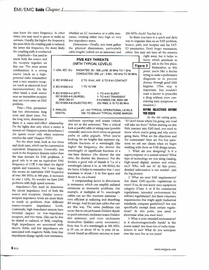
We try to gather information on atleast five key parameters, which we dubFAT-ID, which stands for frequency, ampli-tude, time, impedance, and dimensions. Lateron, you'll hear more about "fatness" andEMI, so this makes a good EMI mnemonic(or maybe a bad pun).
Frequency—This is a key parameter forany EMI problem. If you have an EMIproblem with a communications system(or an FCC emissions test failure), you
www. emiguru. com KGA5
EMI/EMC Guide Chapter 1
1. USA, I EC, EU
2. IEC 61000-4-2
3. IEC 61000-4-3
ANALOGDIGITAL
may know the exact frequency. At othertimes, you may need to guess or make anestimate. Usually, the higher the frequency,the more likely the coupling path is radiated;the lower the frequency, the more likelythe coupling path is conducted.
Amplitude—You need toassess both the source andthe receptor together onthis one. The most severecombination is a strongsource (such as a high-powered radio transmitter)near a very sensitive recep-tor (such as microvolt-levelinstrumentation). On theother hand, a weak sourcenear an insensitive receptormay not even cause an EMIproblem.
Time—This parameterhas two dimensions: longterm and short term. Forthe long term, determine ifthere is a cause-and-effect relationship.Do the lights dim only when a motor isturned on? (Suspect a power disturbance.)Do upsets occur only when someonetouches the unit? (Suspect BSD.)
For the short term, look at rise timesand clock rates, which can be converted toequivalent frequencies. Generally, youwork in the frequency domain rather thanthe time domain for EMI problems. Agood rule is to use an equivalent EMIfrequency of l/(7t X rise time) for digitalsignals and transients. For 1-nsec logic,this means an equivalent EMI frequencyof over 300 MHz; at 300 psec, it increasesto over 1 GHz. No wonder we have EMIproblems with high-speed systems.
Impedance—You need to determinethe circuit impedance level of both thesource and receptors. Similar source-receptor impedance levels are more likelyto result in problems than differentsource-receptor impedance levels.Conversely, high-impedance sources haveminimal impact on low-impedancereceptors, and vice versa. This can be alsobe related to radiated, or field, coupling.High impedances are associated withelectric fields, and low impedances areassociated with magnetic fields. Note thatimpedances change rapidly near resonance,
whether an LC resonance or a cable reso-nance, creating either very high or verylow impedance states.
Dimensions—Finally, you must gatherthe physical dimensions, particularlycable lengths (which act as antennas) and
FIVE KEY THREATS(WITH TYPICAL LEVELS)
RADIATED: 30 - 300 jiV/M, 30 MHz TO 1 GHzCONDUCTED: 250 pV - 3 MV, 150 kHz TO 30 MHz
2 TO 15 kV, AIR 2 TO 8 kV CONTACT
300-MHz clock? You bet it is.So there you have it: a quick and dirty
way to organize data on an EMI problem.Source, path, and receptor and the FAT-ID parameters. Don't forget resonances,either. You may not have all the answers
right away, but it helps toknow which questions to
ask in the first place.Remember, at this
1 TO10V/M
4. IEC 61000-4-4 (EFT)IEC 61000-4-5 (SURGE)
IEEE C62.41IEC 61000-4-6 (INJECTED RF)
1-TO 4-kV BURST1-TO 4-kV TRANSIENT6 kV/SOOOA CM, 500A DM10V RMS, 0.15 TO 80 MHz
puV - mV TYPICAL OPERATIONAL LEVELS100- TO 500-mV TYPICAL NOISE MARGIN
enclosure openings and seams (whichalso act as slot antennas). Take a criticallook at parallel cable or wiring runs (possiblecrosstalk) and even short wires on groundpaths or cable pigtails. What you'relooking for are lengths that represent sig-nificant fractions of a wavelength (thehigher the frequency, the shorter thewavelength) or significant fractions of arise-time distance (the shorter the risetime, the shorter the distance). For theformer, a good rule of thumb is llia of awavelength (about 6 in. at 100 MHz); forthe latter, it helps to remember that 1 nsectranslates to about 1 ft in free space andabout 6 in. on a board.
A compounding factor in dimensionsis resonance, which can amplify radiatedemissions or immunity problems. Forexample, at multiples of 1A, wavelengthcables can act like resonant antennas —very efficient at radiating and absorbingRF energy. And it's not just cables that canact this way. The same problems canoccur due to circuit boards (hidden dipoleor patch antenna), enclosure seams (hiddenslot antenna), and even enclosuresthemselves (hidden cavity resonators.)Note that 1A of a wavelength at 300 MHzis 25 cm, or about 10 in. Is your 10-in.circuit board an efficient antenna to your
point, you're like a doctortrying to make a preliminarydiagnosis or to preventdisease through good EMIhygiene. (This step isimportant. You wouldn'twant a doctor to prescribea drug without even con-sidering your symptoms orsituation.)
DEFINE OBJECTIVES BEFOREYOU BEGIN
As the old saying goes,"If I don't know where I'm going, any roadwill take me there." Before starting on thislittle journey into EMI-land, you need toknow where you're going and why you'regoing there. What are the objectives andthe constraints? Here are five key ques-tions we ask our clients when we beginworking with them on EMI design issues.
1. What are you designing? Is it asupercomputer or a control system? Whattype of technology are you using (analog,high-speed digital, motors and relays,etc)? Who will use it? At this point,detailed information is not needed—justthe big picture.
2. What are your EMI requirements?Are there EMI-specific regulations tomeet? If so, do you know your equipmentcategory (Class A or B for commercialregulations, intended environment formilitary regulations)? Are there voluntaryrequirements that might apply (industrialstandards, company guidelines)? Are youspecifically exempt from certain regula-tions? At this point, you need todetermine what you must meet.
3. What is your intended environment?Is it electromagnetically harsh? Is thepower noisy? Are there lots of radio trans-mitters in use? What do you anticipateover the next five or ten years?
BKGA www. ermguru. com
Even if you're exempt from mandatoryEMI requirements, you may want to applyyour own internal voluntary standards. Forexample, industrial controls are generallyexempt from both emission and immuni-ty standards in the United States, butmany industrial manufacturers applytheir own stringent EMI standards totheir products. As a conscientious design-er, you need to determine what you shouldmeet, not just what you must meet.
4. What are your nontechnical con-straints? What are your typical productscosts? What are your anticipated volumes?What is your market window? Althoughnontechnical, these are valid engineeringconcerns. If you have a high-volume,price-sensitive product, then shaving thelast few pennies out of your EMI fixesmakes sense. On the other hand, if you'reonly building a hundred units and eachone costs $100,000, it's probably cheaperto overdesign than to optimize the design.Look at the total life-cycle costs, not justthe individual component cost.
5. What is the cost of failure? Whathappens if your equipment fails in thefield? (A single field failure can easily costthousands.) How much will it cost to re-test and requalify your equipment?(Typical costs range from $25,000 to$50,000 when you factor in engineeringtime.) How much will it cost if yourequipment is named in a lawsuit?(Probably $100,000 and up. We've seenseveral cases where EMI was blamed in alawsuit. Right or wrong, it happens.) Lookat your risk and consider it as you makeyour EMI decisions.
After you've defined your objectives,you're ready to begin. By the way, don't beafraid to make tradeoffs, and when youdo, be sure to have a back-up plan.
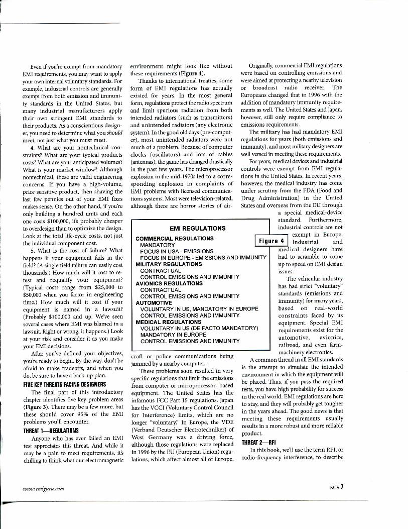
FIVE KEY THREATS FACING DESIGNERSThe final part of this introductory
chapter identifies five key problem areas(Figure 3). There may be a few more, butthese should cover 95% of the EMIproblems you'll encounter.
THREAT 1—REGULATIONSAnyone who has ever failed an EMI
test appreciates this threat. And while itmay be a pain to meet requirements, it'schilling to think what our electromagnetic
environment might look like withoutthese requirements (Figure 4).
Thanks to international treaties, someform of EMI regulations has actuallyexisted for years. In the most generalform, regulations protect the radio spectrumand limit spurious radiation from bothintended radiators (such as transmitters)and unintended radiators (any electronicsystem). In the good old days (pre-comput-er), most unintended radiators were notmuch of a problem. Because of computerclocks (oscillators) and lots of cables(antennas), the game has changed drasticallyin the past few years. The microprocessorexplosion in the mid-1970s led to a corre-sponding explosion in complaints ofEMI problems with licensed communica-tions systems. Most were television-related,although there are horror stories of air-
EMI REGULATIONS
COMMERCIAL REGULATIONSMANDATORYFOCUS IN USA - EMISSIONSFOCUS IN EUROPE - EMISSIONS AND IMMUNITY
MILITARY REGULATIONSCONTRACTUALCONTROL EMISSIONS AND IMMUNITY
AVIONICS REGULATIONSCONTRACTUALCONTROL EMISSIONS AND IMMUNITY
AUTOMOTIVEVOLUNTARY IN US, MANDATORY IN EUROPECONTROL EMISSIONS AND IMMUNITY
MEDICAL REGULATIONSVOLUNTARY IN US (DE FACTO MANDATORY)MANDATORY IN EUROPECONTROL EMISSIONS AND IMMUNITY
craft or police communications beingjammed by a nearby computer.
These problems soon resulted in veryspecific regulations that limit the emissionsfrom computer or microprocessor- basedequipment. The United States has theinfamous FCC Part 15 regulations. Japanhas the VCCI (Voluntary Control Councilfor Interference) limits, which are nolonger "voluntary." In Europe, the VDE(Verband Deutscher Electrotechniker) ofWest Germany was a driving force,although those regulations were replacedin 1996 by the EU (European Union) regu-lations, which affect almost all of Europe.
Originally, commercial EMI regulationswere based on controlling emissions andwere aimed at protecting a nearby televisionor broadcast radio receiver. TheEuropeans changed that in 1996 with theaddition of mandatory immunity require-ments as well. The United States and Japan,however, still only require compliance toemissions requirements.
The military has had mandatory EMIregulations for years (both emissions andimmunity), and most military designers arewell versed in meeting these requirements.
For years, medical devices and industrialcontrols were exempt from EMI regula-tions in the United States. In recent years,however, the medical industry has comeunder scrutiny from the FDA (Food andDrug Administration) in the UnitedStates and overseas from the EU through
a special medical-devicestandard. Furthermore,industrial controls are not
1 exempt in Europe.F i g u r e 4 [ Industrial and
medical designers havehad to scramble to comeup to speed on EMI designissues.
The vehicular industryhas had strict "voluntary"standards (emissions andimmunity) for many years,based on real-worldconstraints faced by itsequipment. Special EMIrequirements exist for theautomotive, avionics,railroad, and even farm-machinery electronics.
A common thread in all EMI standardsis the attempt to simulate the intendedenvironment in which the equipment willbe placed. Thus, if you pass the requiredtests, you have high probability for successin the real world. EMI regulations are hereto stay, and they will probably get tougherin the years ahead. The good news is thatmeeting these requirements usuallyresults in a more robust and more reliableproduct.
THREAT 2—RFIIn this book, we'll use the term RFI, or
radio-frequency interference, to describe
www. emiguru. com KGA?
EMI/EMC Guide Chapter 1
the problem of interference to a systemfrom a nearby transmitter. In terms of ourdiagnostic model, the source is a radiotransmitter, the path is electromagneticradiation, and the receptor is a system thatis upset by the RF energy.
RFI is a serious threat to all modernelectronic systems, due in large part to theproliferation of radio transmitters, includingboth large, high-power systems (television,radar, telemetry) as well as small, low-powersystems (handheld radios and cellulartelephones). The threat is particularlyacute with sensitive analog circuitry,which can be overwhelmed by a nearbysource of RF energy.
The problem is not always with highpower and big antennas. In fact, most ofthe problems we see today are caused bylow-power handheld radios operatedclose to equipment. The important parame-ter is field strength, which is a function ofboth the transmitter power and thedistance from the antenna. Typical failurelevels are at electric field strengths of 1 tolOV/m. As a rule of thumb, a 1W radio at1m has a field strength of about 5V/m, soproblems with small handheld radios canand do occur.
The European immunity limits are inthe 1 to lOV/m range. Meeting these realisticlevels can be difficult, however, andrequire careful attention to EMI designdetails. The simple emission approachesalone are usually inadequate.
THREAT 3—ELECTROSTATIC DISCHARGEBSD is also a serious threat to modern
electronic systems. Incidentally, in thisguide, the term "BSD" describes the actualdischarge to a system, not to individualcomponents.
It no longer takes a direct discharge tocause problems; the intense electromag-netic field from a nearby indirect dischargecan easily upset a system. We've seen thiseffect up to 20 ft away.
Typically, the indirect discharge causesupsets, and the direct discharge causesupset or damage. The damage may beimmediate or latent.
The source of indirect discharges canbe insidious. Most of today's requirementsare based on human discharge. For example,a person touches a file cabinet and a nearby
computer hangs. But recent researchsuggests that there are many sources ofindirect discharge. One of the mostinteresting is the "micro-discharge" thatoccurs when someone sits down or getsup from a common desk chair. We oncesaw our EMC colleague Doug Smithdemonstrate this effect with a simple AMradio next to a chair. When someone gotout of the chair, the radio would cracklefor a minute or more. Doug has been ableto correlate these micro-discharges toactual computer failures. What will weneed to worry about next?
A human BSD event is very rapid,typically with 1- to 3-nsec rise times andpeak currents in the tens of amperes. Thehigh currents and high rates of changecause EMI problems. BSD is considered ahigh-frequency problem; at 1 nsec, theequivalent EMI frequency is greater than300 MHz. This may not be fast enough forall cases, though, as recent BSD tests havemeasured BSD spikes in the 100-psecrange, which would push the equivalentEMI frequency well into the gigahertzrange.
You need to consider BSD in any newdesign, regardless of whether it is requiredby regulations. The laws of physics dictatethat it will be an EMI problem.
THREAT 4—POWER DISTURBANCESPower disturbances are emerging as a
serious EMI problem for all electronicsystems. It's not that the environment isgetting worse, but rather that modernelectronic systems are becoming morevulnerable to power-line disturbances.The problem is compounded by the lackof definitions and guidelines, althoughthis situation is beginning to change.
Power guidelines range from simplehigh/low-voltage limits to more sophisti-cated requirements such as the EFT (elec-trically fast transient) or the lightning surgetransient. EFT simulates arcing and otherhigh-speed noise that can play havoc withmicroprocessor-based systems. The highspeed is usually ignored by older, slowerelectronics. The lightning transient test canbe destructive, but then so can an actuallightning hit to the system power lines.Recent power guidelines also call forinjecting RF into the power lines, which
simulates having a nearby radio transmitterspraying the power wiring with RF.
Analog and digital circuits responddifferently to power disturbances and thatcan confuse things. Digital circuits areeasily fooled by spikes, and analog circuitscan be fooled by sags, surges, and RFenergy. Both types of circuits can beaffected by severe long-term sags, whichcan starve the power supply of neededenergy.
There is a new concern over power-lineharmonics, caused by nonlinear loadssuch as switched-mode power supplies orother electronic loads. These loads typicallyconsume power at the peak of the cycle,rather than over the entire sine wave. Thiscan cause harmonic generation andwaveform distortions that stress thepower-distribution system. As a result,new regulations and guidelines haveemerged for power-line harmonics and itsfirst cousin, flicker.
THREAT 5—SELF COMPATIBILITYThe final threat is incompatibility
internal to the system and includesproblems with mixed technologies, suchas analog/digital or motors/relay/digital.In the first case, the digital circuits typicallyjam the analog circuits; in the second case,the motors and relays jam the digitalcircuits. There is a third case, high-speeddigital, where the digital circuits jamthemselves. (This important special caseis often referred to as signal integrity.)
Although most designers are wellaware of these problems, they may notconsider them EMI problems.Nevertheless, many of the same designtechniques can be applied equally well toproblems entirely inside the system.Remember, the laws of physics don't carewhere you draw the boundaries.
Finally, you can prevent many EMIproblems by paying attention at the internallevels. You can save money, too. A few centsin decoupling capacitors on critical circuitsis much cheaper than several dollars inshielding or filtering, and it probablyresults in a more solid design as well.Remember, ever)' EMI problem ultimatelybegins or ends at the circuit level. D
SKGA www. emiguru. com
EMI/EMC Guide
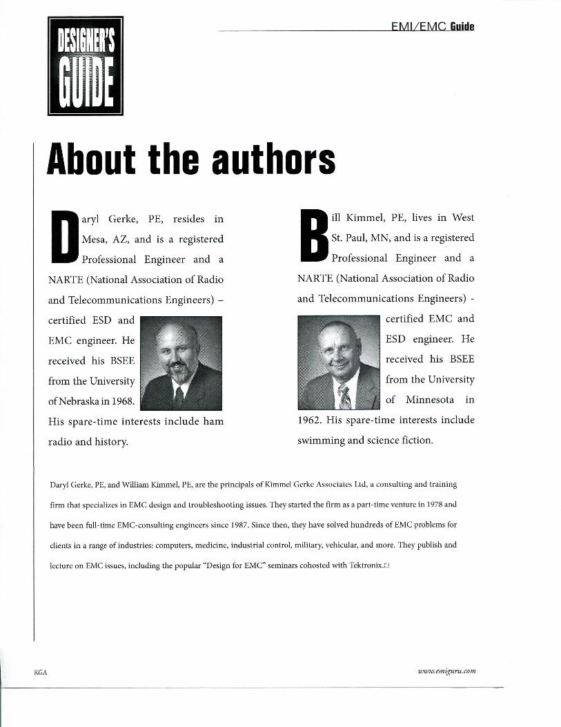
About the authors
D aryl Gerke, PE, resides in
Mesa, AZ, and is a registered
Professional Engineer and a
NARTE (National Association of Radio
and Telecommunications Engineers) -
certified ESD and
EMC engineer. He
received his BSEE
from the University
of Nebraska in 1968.
His spare-time interests include ham
radio and history.
B ill Kimmel, PE, lives in West
St. Paul, MN, and is a registered
Professional Engineer and a
NARTE (National Association of Radio
and Telecommunications Engineers) -
certified EMC and
ESD engineer. He
received his BSEE
from the University
of Minnesota in
1962. His spare-time interests include
swimming and science fiction.
Daryl Gerke, PE, and William Kimmel, PE, are the principals of Kimmel Gerke Associates Ltd, a consulting and training
firm that specializes in EMC design and troubleshooting issues. They started the firm as a part-time venture in 1978 and
have been full-time EMC-consulting engineers since 1987. Since then, they have solved hundreds of EMC problems for
clients in a range of industries: computers, medicine, industrial control, military, vehicular, and more. They publish and
lecture on EMC issues, including the popular "Design for EMC" seminars cohosted with Tektronix.n
KGA www. emiguru. com
EDN DESIGNER'S GUIDE TO ELECTROMAGNETIC COMPATIDILITYis now published by
Kimmel Cerke Associates, Ltd.EMC Consulting Engineers
ARIZONA OFFICE 1-888-EMI-GURU MINNESOTA O F F I C EDaryl Gerke, RE. (toll free) William Kimmel, RE.2538 W. Monterey Ave. 628 LeVander WayMesa, AZ 85202 WWW.EMIGURU.COM S. St. Paul, MN 55075
Copyright © 2005 by Kimmel Gerke Associates, Ltd.