Embed Size (px)
Citation preview

®
OSMONICSTONKAFLO PUMPS
SS SERIES
INSTALLATION, OPERATION, AND MAINTENANCE MANUAL
For SS500, SS1000, andSS1800 Series
Tonkaflo CentrifugalPumps with X, XB, and XC
Motor AdaptersWithout Bearing Frames
GE InfrastructureWater & Process Technologies


INSTALLATION, OPERATION AND MAINTENANCE MANUAL
FOR SS500, SS1000 AND SS1800 SERIESTONKAFLO CENTRIFUGAL PUMPS
WITH X-, XB- OR XC-FRAMESMOTOR ADAPTERS WITHOUT
BEARING FRAME
TABLE OF CONTENTS
Page
1.0 INTRODUCTION 1
2.0 TONKAFLO SPECIFICATIONS 2
2.1 Capacities 22.2 Maximum Developed Boost Pressure 32.3 Maximum Recommended Operating Temperature 32.4 Standard Materials of Construction 32.5 Special Materials of Construction 32.6 Pump Nomenclature 42.7 Special Liquids 4
3.0 PUMP INSTALLATION 5
3.1 Inspection 53.2 Pump Mounting and Location 53.3 Inlet and Discharge Piping and Connections 5
3.3.1 Inlet Piping 53.3.2 Discharge Piping 63.3.3 Pump Piping Connections 73.3.4 Inlet Line Screen/Filter 73.3.5 Discharge Screen (Strainer) 7
3.4 Pump Priming 83.5 Protection Against Running Dry 83.6 Motor Wiring 9
3.6.1 Single-Phase Motors 93.6.2 Three-Phase Motors 93.6.3 Three-Phase Power Imbalance 10

Page
4.0 GENERAL TROUBLESHOOTING FOR ALL PUMPS 12
4.1 Troubleshooting Chart 124.2 Mechanical Seal Leakage 134.3 Mechanical Seal Replacement: SS500, SS1000 and
SS1800 Series Pumps 134.4 High-Pressure Mechanical Seal Replacement: SS500, SS1000
and SS1800 Series 16
5.0 TONKAFLO PUMP FIELD MAINTENANCE 17
5.1 Motor Bearing Lubrication 175.2 Motor Removal: XB and XC Motor Adapter Pump 175.3 Motor Installation: XB and XC Motor Adapter Pump 185.4 Motor Removal: X Motor Adapter Pump 185.5 Motor Installation: X Motor Adapter Pump 19
6.0 LIQUID END, TONKAFLO SERVICE POLICY 21
7.0 TONKAFLO PUMP RETURNED GOODS AUTHORIZATION(RGA) PROCEDURE 22
7.1 Motor Warranty 227.2 In-of-Warranty Pump Failure 227.3 Out-of-Warranty Pump Failure 22
8.0 DIMENSIONAL DRAWINGS 23
8.1 500X Motor Adapter Pump 238.2 500XB Motor Adapter Pump 248.3 1000X and 1800X Motor Adapter Pump 258.4 1800XB Motor Adapter Pump 268.5 1800XC Motor Adapter Pump 27
9.0 CUTAWAY DRAWINGS 28
9.1 X Motor Adapter Pump 289.2 XB and XC Motor Adapter Pump 29

Page
10.0 STANDARD MODEL PARTS LIST 30
10.1 Spare Parts List 3010.2 Accessories 3110.3 Mechanical Seal Replacement Kit 32
11.0 ORDERING PARTS 33
12.0 TONKAFLO PUMP WARRANTY 34
LIST OF FIGURES
Figure Title
3.1 Inlet Piping 63.2 Installation of Discharge Screen 83.3 Changing Motor Rotation 103.4 Rolling the Leads to Balance Current Draw 114.5 Removal of Pump Liquid-End from Motor Adapter 144.6 Removal of Mechanical Seal Holder from
Motor Adapter 144.7 Removal of Mechanical Seal from Pump Shaft
and Cavity of Mechanical Seal Holder 158.8 500X Motor Adapter Pump 238.9 500XB Motor Adapter Pump 248.10 1000X and 1800X Motor Adapter Pump 258.11 1800XB Motor Adapter Pump 268.12 1800XC Motor Adapter Pump 279.13 X Motor Adapter Pump 289.14 XB and XC Motor Adapter Pumps 29
LIST OF TABLES
Table Title
2.1 Capacities 22.2 Maximum Developed Boost Pressure 3


1.0 INTRODUCTION
This manual contains information important to the installation, operation, and maintenanceof your Tonkaflo multi-stage centrifugal pump. Your Tonkaflo pump has been designed forreliable service in many types of pumping applications. Proper installation and normal main-tenance will help ensure extended pump life and prevent costly downtime.
Before installing and operating your Tonkaflo pump, read these instructions carefully andkeep this manual handy for future reference. This manual is intended for general mainte-nance only.
Further information may be obtained by contacting your nearest Tonkaflo distributor orGE Infrastructure at:
GE InfrastructureWater & Process Technologies5951 Clearwater DriveMinnetonka, MN 55343-8995 USA
Phone: (952) 933 - 2277Toll Free: (800) 848 - 1750Fax: (952) 988 - 6060
This manual is not intended for repair or overhaul of the Tonkaflo pump liquid ends.
Only the factory and those certified by the Factory Service School are authorized to repair,service, or overhaul of Tonkaflo pump liquid ends.
Your new Tonkaflo multi-stage centrifugal pump is designed for quiet, smooth-running, andhighly efficient operation. The materials of construction make Tonkaflo pumps suitable formany chemical and pure water applications.
Tonkaflo pumps' unique modular design allows the user to choose the number of stageswhich most closely match the desired performance and, thereby, achieve the highest pump-ing efficiency. Unlike many other pump manufacturers, Tonkaflo will produce pumps to fityour particular applications should a standard model pump not suit your requirements.
NOTE: This manual, along with all GE Infrastructure manuals, is available atwww.ge.water.com.
1
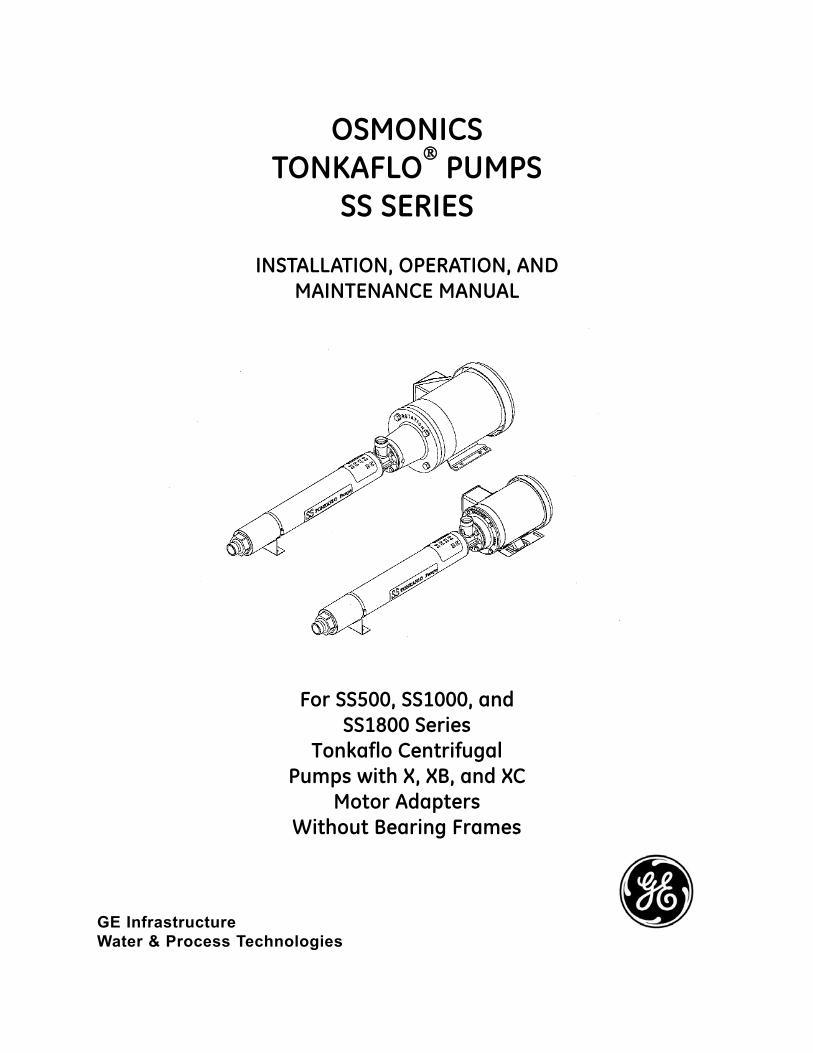
2.0 TONKAFLO SPECIFICATIONS
The Tonkaflo pumps covered in this instruction manual are the lower capacity SS500, SS1000,and SS1800 Series pumps. These pumps cover a flow range of 1.5 - 18 gpm (0.34 - 4.1 m3/h)with single unit pressure up to 700 psig (48.3 barg). The capacity and discharge pressure canbe increased by operating pumps in parallel or series, respectively. There is no maximum limiton capacity when operating Tonkaflo pumps in parallel. When operating pumps in series, themaximum rated discharge is 750 psig (51.7 barg) with standard pumps, and 1000 psig(69 barg) with optional high-pressure construction on the downstream pump. With inlet pres-sures greater than 200 psig (13.8 barg), optional high-pressure mechanical seals should beused.
2.1 Capacities
Table 2.1Capacities
NOTE: There must be adequate flow at all times through the pump to prevent excessiveheat build-up.
2
SSSeries
500
1000
1800
2900 rpm50 Hertz
Minimum - Maximum
1 - 6 gpm(0.23 - 1.4 m3/h)
3.3 - 11 gpm(0.75 - 2.5 m3/h)
4 - 17.5 gpm(0.91 - 4.0 m3/h)
3500 rpm60 Hertz
Minimum - Maximum
1.5 - 7 gpm(0.34 - 1.6 m3/h)
4 - 13 gpm(0.91 - 30. m3/h)
5 - 21 gpm(1.14 - 4.8 m3/h)
MaximumEfficiency
40%
49%
57%

2.2 Maximum Developed Boost Pressure
Table 2.2Maximum Developed
Boost Pressure
2.3 Maximum Recommended Operating Temperature
The maximum recommended operating temperature range is 125°F (52°C). The max-imum operating temperature is dependent upon the operating pressure. For hightemperature applications, consult the factory for special materials of construction.
The maximum recommended temperature is stated on the pump case. The temper-ature stated is for the design flow and pressure.
2.4 Standard Materials of Construction
SS: Wetted castings and pump shaft are 316 stainless steel (SS). The pump casingis 316SS. Impellers and diffusers are Noryl. The mechanical seal has a carbonrotating face and a ceramic stationary face. The secondary sealing element ofthe mechanical seal is Buna-N. The O-rings and diffuser bearings are Buna-N.
2.5 Special Materials of Construction
Optional ethylene propylene (EPDM), Viton*, and Teflon* elastomers are available.Contact the factory.
3
* Viton and Teflon are trademarks of E.I. DuPont de Nemours and Company, Inc.
SSSeries
500
1000
1800
60 Hertz
700 (48.3)
340 (23.4)
680 (46.9)
50 Hertz
630 (43.4)
300 (20.7)
570 (39.3)
60 Hertz
58
28
48
50 Hertz
76
N/A
56
Maximum DevelopedPressure
psig (barg)
Number of CentrifugalStages
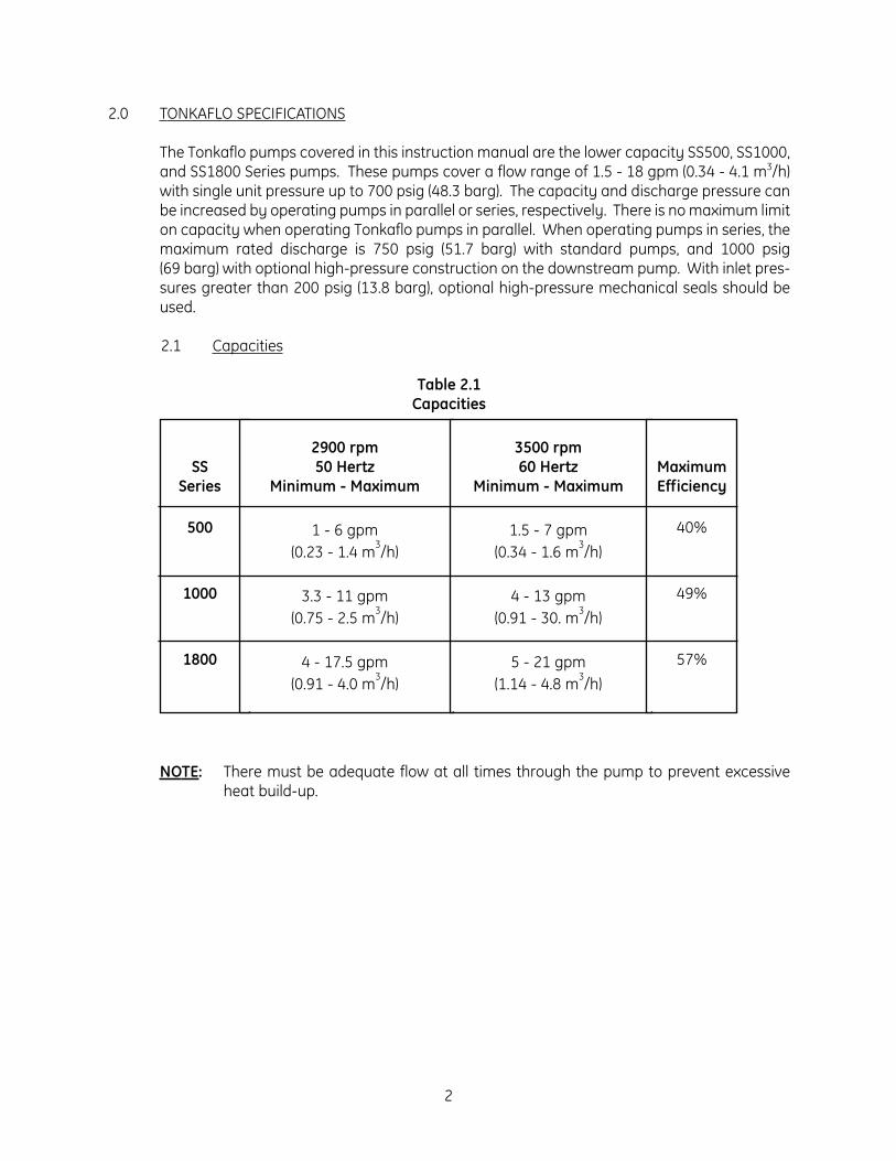
2.6 Pump Nomenclature
Example:
2.7 Special Liquids
For liquids other than water, aqueous solutions, or corrosive solutes, consult thefactory for compatibility.
4
M o d e l S S 5 0 5 X
SS = Materials of Construction5 = Series 50005 = Number of StagesX = Motor Adapter,
No Bearing Frame,56J Motor
M o d e l S S 1 8 4 8 X B - 5 0
SS = Materials of Construction18 = Series 180048 = Number of StagesXB = Motor Adapter,
No Bearing Frame,182/184TC Motor
50 = 50 Hertz Operation

3.0 PUMP INSTALLATION
3.1 Inspection
Your pump was inspected and tested at the factory prior to shipment to ensure itmeets the requirements of your order. It is suggested the pump be checked uponreceipt for possible damage due to shipping. Any damage should be immediatelyreported to the carrier.
3.2 Pump Mounting and Location
The pump is supported by the motor base, and on longer pumps, a support at the dis-charge end. The X, XB, and XC motor adapter pumps may be mounted and operatedin either a horizontal or vertical position. The vertical position requires the motor tobe up.
The inlet casting may be rotated to any of four positions by removing the four (4) boltson the inlet casting, turning the inlet casting to the desired position and replacing the4 bolts.
When mounting the pump, be sure the pump casing support and motor base are inline and on the same plane so that no stress results in the pump after fastening down.
CAUTION: The inlet and discharge piping should be independently supported.
3.3 Inlet and Discharge Piping and Connections
3.3.1 Inlet Piping
THE INLET PIPING AND PUMP MUST BE FILLED WITH LIQUID (i.e., PRIMED) BEFORE START-UP. A pressure/vacuum gauge installed in theinlet piping to measure positive or negative pressure is recommended. Besure the pump is not mounted above the liquid source and the inlet (suction)plumbing not restricted so adequate suction pressure is available.
The inlet piping should be at least as large as the pump inlet port. The dis-charge piping should be sized to properly handle the maximum flow and pres-sure developed by the pump.
The recommended pipe size for most applications should result in frictionalline loss of 5 psig/100 feet (0.34 barg/100 meters) or less for suction lines and10 psig/100 feet (0.7 barg/100 meters) or less for discharge lines. A larger pipesize will reduce the frictional line loss.
The pump inlet piping should be designed to avoid areas where air may betrapped and accumulate. Keep the inlet pipe free of high points, which couldtrap air and could disrupt pump priming and start-up. Pump inlet pipe sizechanges just ahead of the pump should be tapered. Reducers should beeccentric to avoid air pockets.
5

IMPORTANT: Should your application require pump operation with a neg-ative gauge pressure at the inlet, consult the factory or yourlocal Tonkaflo pump distributor.
When the pump operates with a suction lift , the suction pipe should slopeupward to the pump from the source of supply. Provision must be made forpriming the pump. To maintain pump prime, a foot valve can be used with anopening at least as large as the inlet piping.
When pumping liquid from a tank, the suction line must be submergedenough so air is not drawn into the suction line from a vortex. Increasing thesize of the inlet pipe to reduce the velocity will help to prevent the vortex fromforming.
Hot liquids within the temperature range of the pump must have sufficient positive head to prevent vaporization at the impeller inlet. The Net PositiveSuction Head (NPSH) required data are included on the pump performancecurves provided with this instruction manual.
The pump must never be throttled on the suction side.
After installation, test the suction line with water with a range of 20 - 100 psig(1.4 - 6.9 bar) pressure to detect any leaks.
Figure 3.1Inlet Piping
3.3.2 Discharge Piping
The discharge piping should be sized to properly handle the maximum flowand pressure developed by the pump.
6

Size selected should result in frictional line loss of 5 psi/100 ft (1.1 kPa/M) orless for suction lines and 10 psi/100 ft (2.3 kPa/M) or less for discharge lines.A larger pipe size will reduce the frictional line loss.
WARNING: THE PUMP MUST NOT RUN WITH A CLOSED DISCHARGE ORIRREVERSIBLE DAMAGE TO THE WETTED INTERNAL PARTSOF THE PUMP WILL RESULT!
3.3.3 Pump Piping Connections
The standard inlet and discharge connections for a Series 500 pump is a3/4-inch NPT female pipe thread, and for Series 1000 and 1800 pumps is1-1/4-inch Victaulic couplings/clamped unions with gasket. Victaulic cou-plings are available worldwide. Contact the factory or your local industrialpiping wholesaler.
3.3.4 Inlet Line Screen/Filter
This is a precision multi-stage pump with close tolerances to provide maxi-mum efficiency. It is good practice to install a large area 30-mesh or finerscreen, or a cartridge filter in the pump inlet line to collect any foreign objectsor large particles. Size the screen or filter so as to induce a minimal pressuredrop.
WARNING: THE PUMP MUST NOT BE OPERATED WITH RESTRICTED SUC-TION LINE (INLET) FLOW.
Positive gauge pressure must be maintained at the pump inlet (downstreamfrom the screen or filter). A clogged screen or filter will result in a greaterpressure drop than a clean screen or filter. To prevent possible pump dam-age from low inlet pressure, a low-pressure alarm or shut-off switch should belocated between the screen or filter and the pump. A low-flow shut-off switchshould also be located in the same area.
3.3.5 Discharge Screen (Strainer)
A 30-mesh screen (available as an accessory for 500, 1000 and 1800 Seriespumps) located in the discharge piping will protect your process fluid shouldthe pump be damaged. The installation of the screen is shown inFigure 3.2 (Installation of Discharge Screen).
7

Figure 3.2Installation of
Discharge Screen
3.4 Pump Priming
IMPORTANT: THE INLET PIPING AND PUMP MUST BE FILLED WITH LIQUID (i.e.,PRIMED) BEFORE START-UP.
If the pump is above the liquid source, fill the pump and supply line with liquid froman external source.
WARNING: THE PUMP MUST BE SHUTOFF IMMEDIATELY IF PRIME IS LOST TOAVOID POSSIBLE DAMAGE TO THE INTERNALS OF THE LIQUID END.
WARNING: NEVER RUN PUMP DRY.
The liquid end of your Tonkaflo pump is lubricated by the process fluid. The pumpmust never be run dry to avoid damage to the liquid end.
3.5 Protection Against Running Dry
It is suggested that controls to protect the pump from running dry be used. Thesecontrols include: pressure switches, flow switches, and temperature switches.
8

3.6 Motor Wiring
3.6.1 Single-Phase Motors
When initially connecting to the power source, be certain that the motor volt-age connections and available line voltage are the same. Connect electricalwires as shown on the motor wiring diagram located on the motor name-plate, electrical junction box, junction box cover, or wiring tag. Be sure yourpump is electrically grounded at the junction box on the motor.
3.6.2 Three-Phase Motors
The wiring diagram located on the motor nameplate, electrical junction box,junction box cover, or wiring tag should be used to correctly wire the motoraccording to the line voltage available. Be sure your pump is electricallygrounded at the junction box on the motor.
CAUTION: The 500X, 1000X and 1800X motor adapter pumps have athreaded motor shaft. Reverse operation can damage themotor shaft, pump shaft, or centrifugal stages.
Before Starting Three-Phase Motors:
STEPS
1. Prime pump before applying power to avoid damage to the pump.
2. Apply power for ONE SECOND MAXIMUM to check the direction ofmotor shaft rotation. The motor shaft should turn in a clockwise direc-tion as viewed from the motor end. The direction of rotation for three-phase motors may be reversed by interchanging any two (2) leads(Figure 3.3, Changing Motor Rotation).
Three-phase motors can run in either direction, depending on howthey are connected to the power supply. When the three cable leadsare first connected to the power supply, there is a 50% chance thatthe motor will run in the proper direction. To make sure the motor isrunning in the proper direction, carefully follow the procedure below.
STEPS
A. Start the pump and note the pressure and flow rate developedat the pump discharge.
B. Stop the pump and interchange any of the two leads.
C. Start the pump again and recheck the flow rate and pressure.
9
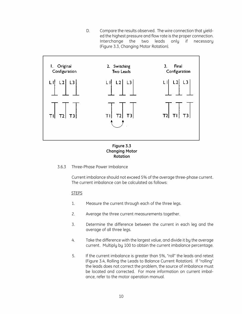
D. Compare the results observed. The wire connection that yield-ed the highest pressure and flow rate is the proper connection.Interchange the two leads only if necessary(Figure 3.3, Changing Motor Rotation).
Figure 3.3Changing Motor
Rotation
3.6.3 Three-Phase Power Imbalance
Current imbalance should not exceed 5% of the average three-phase current.The current imbalance can be calculated as follows:
STEPS
1. Measure the current through each of the three legs.
2. Average the three current measurements together.
3. Determine the difference between the current in each leg and theaverage of all three legs.
4. Take the difference with the largest value, and divide it by the averagecurrent. Multiply by 100 to obtain the current imbalance percentage.
5. If the current imbalance is greater than 5%, “roll” the leads and retest(Figure 3.4, Rolling the Leads to Balance Current Rotation). If “rolling”the leads does not correct the problem, the source of imbalance mustbe located and corrected. For more information on current imbal-ance, refer to the motor operation manual.
10

Figure 3.4“Rolling” the Leadsto Balance Current
Draw
11

4.0 GENERAL TROUBLESHOOTING FOR ALL PUMPS
4.1 Troubleshooting Chart
12
MOTOR RUNS HOT OR STOPS
1. Motor surface temperature up to 104°F (40°C) over ambient canoccur. The motor will feel hot to thetouch.
2. Bad connection3. Motor exceeded rated amp draw4. Excessive ambient temperature5. Heater size to small in motor heater6. Binding rotation in the pump shaft7. Bearings not adequately lubricated8. Specific gravity or viscosity of liquid
higher than design conditions9. Motor wired improperly
LOW PRESSURE
1. Pump not adequately primed2. Air leak in inlet piping3. Excessive flow4. Clogged suction line filter or screen5. Reverse rotation of pump shaft6. Foot valve operating improperly7. Wrong ratio for belt drive
PUMP LEAKING
1. Mechanical seal needs replacing2. O-rings in pump casing damaged3. Oil seals need replacing4. Piping not sealed properly
LOW FLOW
1. Restrictions in inlet or discharge2. Foot valve operating improperly3. Air leak in inlet piping4. Air leak in mechanical seal5. Wrong installation of belt drive6. Suction lift too high7. Reverse rotation of pump shaft8. Pump not primed adequately9. Inlet strainer/filter plugged.10. Pump throttling valve on discharge
closed (pump deadheaded)
MOTOR DOES NOT RUN
1. Blown fuse or tripped circuit breaker oroverload heater
2. Motor to hot - allow to cool3. Motor voltage connection and line
voltage different4. Bad connection5. Motor wired improperly6. Wrong ratio for belt drive
PUMP VIBRATION
1. Misalignment of flexible coupling2. Bent pump shaft3. Improper mounting4. Starved suction5. Worn bearings6. Motor out of balance7. Operating beyond specified capacity
range of the pump
4.2 Mechanical Seal Leakage
WARNING: POWER MUST BE DISCONNECTED BEFORE MAINTENANCE!
If liquid is leaking from the hole on the bottom or on either side of the motor adapter,the mechanical seal may need to be replaced. With new pumps, pumps with newmechanical seals, or pumps which have been dormant for long periods, the seal facesmay not be completely seated and a slight leakage will occur. If this leakage contin-ues for more than 60 seconds, the first remedy is to remove the discharge piping andtap the pump shaft using a wooden dowel to seat the seal.
WARNING: BE CAREFUL NOT TO DAMAGE THE SHAFT.
If this does not stop the leak, then the liquid end assembly needs to be partiallyremoved to gain access to the mechanical seal as shown in Figure 4.5 (Removal ofPump Liquid-End from Motor Adapter) or Figure 4.6 (Removal of Mechanical Seal fromMotor Adapter).
The ceramic seal seat also needs to be wiped clean and then coated very lightly withoil or Vaseline. Also, the carbon wear ring needs to be wiped clean and coated light-ly with petroleum grease. Then, reassemble the pump.
4.3 Mechanical Seal Replacement: SS500, SS1000 and SS1800 Series Pumps
NOTE: On Tonkaflo X frame pumps, the mechanical seal must be replaced byremoval of the complete liquid end assembly from the pump shaft. OnTonkaflo XB and XC frame pumps, you can service the mechanical seal byeither removing the complete liquid end assembly from the pump shaft, orby loosening the cone-point set screw which secures the pump shaft to theshaft coupler, and removing the pump shaft with the liquid end assembly.
STEPS
1. Remove the four (4) 5/16-inch bolts and lock washers from the inlet castingand firmly grasp the liquid end (Figure 4.5, Removal of Pump Liquid-End fromMotor Adapter). Pull the liquid end straight off the pump shaft being carefulnot to bend the pump shaft. Two (2) flat-blade screwdrivers may be neededto remove the seal holder from the liquid end assembly.
WARNING: EXTREME CARE MUST BE TAKEN NOT TO BEND PUMP SHAFT!
2. Remove the stainless steel retaining ring (size 5160-62H) from the pump shaftusing the proper size retaining ring pliers (Truarc L1520 or equivalent). Thesepliers are available from the factory or can be purchased from a local source.
13

Figure 4.5Removal of Pump Liquid-End from
Figure 4.6Removal of Mechanical
Seal Holder fromMotor Adapter
14

Figure 4.7Removal of Mechanical Seal from Pump Shaft and Cavity
of Mechanical Seal Holder
3. Remove the rotary portion (spring, washer, and face assembly) of the sealassembly from the pump shaft by rotating and pulling the rotary portion untilit slides off the pump shaft (Figure 4.6, Removal of Mechanical Seal Holderfrom Motor Adapter).
4. Remove the mechanical seal holder from the motor adapter by sliding theholder off the pump shaft. Two (2) flat-blade screwdrivers may be needed toremove seal holder from the motor adapter (Figure 4.6).
5. Remove the stationary seat of the mechanical seal from the cavity of themechanical seal holder (Figure 4.7, Removal of Mechanical Seal from PumpShaft and Cavity of Mechanical Seal Holder).
6. Install the new stationary seat into the seal holder cavity. Lubricate the rub-ber boot on the outside of the stationary seal with petroleum or siliconegrease before replacement. Make sure the stationary seat is fully seated.Lightly lubricate the ground surface of the stationary seat with grease.
15

7. Examine the rubber O-ring on the mechanical seal holder and, if the O-ring isdamaged, replace it with a new one. A new O-ring is included with the facto-ry-supplied Mechanical Seal Replacement Kit (Section 10.3). Be sure to lubri-cate with grease before installing.
8. Place the mechanical seal holder containing the new stationary seat onto thepump shaft and slide it down the shaft until fully engaged with the motoradapter. Care must be taken not to damage seal seat when sliding over thepump shaft.
9. Lubricate the round surface of the pump shaft with grease. After lubrication,replace the rotary portion of the mechanical seal by placing onto the pumpshaft and carefully rotating and pushing it down the pump shaft until it is fullyseated against the stationary portion of the mechanical seal.
WARNING: USE CARE WHEN SLIDING THE ROTARY PORTION OF THEMECHANICAL SEAL OVER THE RETAINING RING GROOVE INTHE PUMP SHAFT. THE RUBBER ON THE MECHANICAL SEALCAN BE DAMAGED IF NOT LUBRICATED WITH GREASE.
10. Place the stainless steel retaining ring back onto the shaft to hold the rotaryportion of the mechanical seal in place with the square edges of the retainingring away from the seal spring. A retaining ring is included in the factory sup-plied mechanical seal replacement kit. Use of retaining rings that are notstainless steel or equivalent may cause the seal to fail in operation.
11. Be sure the retaining ring is properly seated in the groove on the pump shaft.
12. Firmly grasp the liquid end and insert the splined pump shaft into the liquidend by carefully rotating the liquid end clockwise and then counterclockwisewhile applying light pressure toward the motor adapter. Be sure the splinedshaft and splined bore of each impeller meshes properly until the inlet castingmates with the mechanical seal holder. It may be necessary to lift the assem-bly up slightly when rotating it , then place it onto the splined shaft.
WARNING: CARE MUST BE TAKEN NOT TO BEND THE PUMP SHAFT OR TOFORCE THE SHAFT INTO THE IMPELLER BORE.
13. Install the four (4) 5/16-inch bolts and lock washers and tighten.
4.4 High-Pressure Mechanical Seal Replacement: SS500, SS1000 and SS1800 SeriesPumps
High pressure mechanical seals have the same basic design as standard mechanicalseals. Replace them using the same procedure as denoted in Section 4.3 (MechanicalSeal Replacement SS500, SS1000 and SS1800 Series Pumps), Figure 4.6 (Removal ofMechanical Seal Holder from Motor Adapter), and Figure 4.7 (Removal of MechanicalSeal from Pump Shaft and Cavity of Mechanical Seal Holder).
16

5.0 TONKAFLO PUMP FIELD MAINTENANCE
5.1 Motor Bearing Lubrication
Motors up to 3 Hp typically have sealed bearings. Motors of 5, 7.5, and 10 Hp may ormay not have sealed bearings. For these larger motors, lubrication intervals varybetween manufacturers but generally lubrication every 2000 hours is required.Consult Your Local Motor Distributor For Lubrication Advice, or the motor informationsupplied with your pump.
5.2 Motor Removal: XB and XC Motor Adapter Pumps
STEPS
1. Disconnect the motor electrical power.
2. Remove the wiring to the motor.
3. Remove the piping from the pump.
4. Remove the pump mounting bolts, and place the pump on a work bench.
5. Remove the cone-point set screw from the shaft coupler, which is locatedthrough either side port in the motor adapter adjacent to the inlet housing. Donot remove the two knurled cup-point set screws securing the shaft couplerto the motor shaft at this time.
6. Remove the four (4) 5/16-18NC bolts that hold the pump liquid end to themotor adapter.
7. Slide the liquid end assembly away from the motor adapter 1/4- to 1/2-inch(6 - 13 mm).
8. Use two (2) flat-blade screwdrivers or small pry bars to remove the seal hold-er from the motor adapter along with the pump shaft (Figure 4.5, Removal ofPump Liquid-End from Motor Adapter). Remove the liquid-end assemblyincluding the pump shaft as a unit.
9. Remove the four (4) 1/2-12NC bolts that hold the motor adapter to the motorand remove the motor adapter.
10. Loosen the two set screws that hold the shaft coupler to the motor shaft, andremove the shaft coupler. The motor may now be serviced by a qualified ven-dor or replaced (Figure 4.6, Removal of Mechanical Seal Holder from MotorAdapter).
17

5.3 Motor Installation: XB and XC Motor Adapter Pumps
STEPS
1. On a used motor, file the motor shaft smooth where the set screws wereseated.
2. Coat the motor shaft with an anti-seize compound.
3. Slide the shaft coupler onto the motor shaft until fully seated, and tighten thetwo set screws.
4. Place the motor adapter onto the motor, such that the one drain hole is locat-ed down and the four side access ports are horizontal when the pump is rein-stalled.
5. Coat the round end of the pump shaft and shaft key with an anti-seize com-pound.
6. Place the pump liquid-end assembly with pump shaft and shaft key into themotor adapter, with the key aligned with the coupler key way.
7. Install the four (4) 5/16-18NC bolts and tighten.
8. Using a wood dowel, place it against the pump shaft end located in the dis-charge port. Tap on the end of the wood dowel until the pump shaft is fullyseated in the shaft coupler, and then tighten the cone-point set screw(Figure 4.6, Removal of Mechanical Seal Holder from Motor Adapter).
9. Reinstall the pump and pump piping connections.
10. Reinstall the motor wiring.
11. For pump start-up see Section 3.0 (Pump Installation).
5.4 Motor Removal: X Motor Adapter Pumps
STEPS
1. Disconnect the motor electrical power.
2. Remove the wiring to the motor.
3. Remove the piping from the pump.
4. Remove the pump mounting bolts, and place the pump on a work bench.
5. Remove the four (4) 5/16-18NC bolts that hold the pump liquid end to themotor adapter.
18

6. Slide the liquid end assembly off of the pump shaft, taking care not to bendthe pump shaft.
7. Remove the retaining ring and remove. The rotary head of the mechanicalseal.
8. Remove the seal holder along with the stationary seal seat.
9. Remove the four (4) 3/8-16NC bolts that hold the motor adapter to the motor,and remove the motor adapter.
10. Remove the pump shaft assembly where it is screwed to the threaded motorshaft by first heating the joint area to loosen the thread-locking compound.Secure the motor shaft using a vise grip, and loosen the pump shaft assem-bly. An impeller may be used to grip the shaft, taking proper care not to dam-age the impeller. Or, use a vise grip and fabric rug to grip the splined shaft,taking care not to damage the splines.
11. The motor can now be serviced by a qualified service center, or replaced.
5.5 Motor Installation: X Motor Adapter Pumps
STEPS
1. To re-use a repaired motor, clean the threads on the shaft of any thread-sealant residue.
2. Reinstall the pump shaft onto the threaded motor shaft until fully seated.Rotate the pump shaft to make sure it runs true. Run-out should be less than0.03 inch (0.76 mm) for every 10 inches of pump shaft length.
3. Loosen the pump shaft from the motor shaft, apply thread sealant to thethreads, and tighten the shaft again until fully seated. Use standard strengththread sealant on single-phase motors, and a high-strength thread sealant onthree-phase motors.
4. Install the motor adapter onto the motor and install and tighten the four boltsinto the motor.
5. Position the seal holder into the motor adapter, using Vaseline or grease onthe O-ring as a lubricant. Replace the O-ring if damaged.
6. Install a new mechanical seal stationary seat, using Vaseline, grease, or wateras a lubricant on the rubber portion.
7. Install the rotary portion of the mechanical seal using a small amount ofVaseline lubricant on the round body of the shaft, and also on the face of theceramic seat face where the carbon wear ring contacts it .
19

8. Install the retaining ring into the shaft groove with the sharp edges away fromthe motor.
9. Install the liquid end assembly onto the pump shaft. Do not force it in. Rotateand place the liquid end onto the mechanical seal holder until seated againstmotor adapter.
10. Install the four (4) 5/16-inch lock washers and bolts to hold the liquid end ontothe motor adapter and tighten.
11. Reinstall the pump (Section 3.0, Pump Installation).
20

6.0 LIQUID END - TONKAFLO SERVICE POLICY
Sections 4.0 (General Troubleshooting for All Pumps) and 5.0 (Tonkaflo Pump FieldMaintenance) in the Tonkaflo Installation, Operation, and Maintenance Manual were writtento assist our customers in performing minor maintenance in the field of Tonkaflo pumps.Proper maintenance will ensure longer pump life and minimize downtime. Tonkaflo pumpsare manufactured to make field repairs on the mechanical seal a quick and easy process. Ifa repair at the factory is desired, call the factory for a Return Goods Authorization (RGA) number (Section 7.0) and follow the directions provided by a GE representative. For motorproblems, such as worn-out motor bearings, it is recommended that maintenance be done ata local motor repair shop.
WARNING: FIELD SERVICE OF THE LIQUID END, WITH THE EXCEPTION OF MECHANICALSEAL REPLACEMENT, IS NOT RECOMMENDED.
If a liquid end is damaged by running the pump dry, inadequate flow, deadheading, cavita-tion, or other reasons, return it with the motor to the factory for repair.
21

7.0 TONKAFLO PUMP RETURN GOODS AUTHORIZATION (RGA) PROCEDURE
If you wish to return goods for repair, warranty evaluation and/or credit, please have youroriginal sales order or invoice available when you call GE. Call (800) 848-1750 and ask tospeak with Customer Service. A GE Customer Service representative will provide instructionsand a return authorization number which needs to be clearly written on the outside of the boxused to ship your materials. All equipment must be shipped to GE with the freight prepaid bythe customer. Call our Customer Service Center with any questions or issues concerningfreight claims and a representative will discuss your situation.
All materials to be returned must be rendered into a non-hazardous condition prior to ship-ping.
There are two ways to handle a return: (1) send in the pump for repair and return or (2) pur-chase a new pump and when desired, send the defective pump to the factory for repair andreturn.
7.1 Motor Warranty
Motors must be sent to the nearest authorized motor service station center for repair,replacement, and warranty disposition.
7.2 In-Warranty Pump Failure
STEPS
1. Return the defective pump to the factory for repair, on an RGA, within 15 days.from RGA issue date. GE absorbs the cost of repair. The repaired pump willbe returned and is under warranty for the remainder of the original warrantyperiod or three months, whichever is longer.
2. GE will not restock or issue return credit against a new, customer-built , pumppurchase regardless of the warranty status of the failed pump. The warranty(Section 12.0, Tonkaflo Pump Warranty) is 12 months from installation or 15months from receipt, whichever occurs first.
7.3 Out-of-Warranty Pump Failure
Return the pump on an RGA for repair. The pump will be repaired and repair chargesinvoiced to the customer. The warranty for repairs is three months.
22

8.0 DIMENSIONAL DRAWINGS
8.1 500X Motor Adapter Pumps
Figure 8.8500X Motor
Adapter Pump
23

8.2 500 XB Motor Adapter Pumps
Figure 8.9500 XB MotorAdapter Pump
24

8.3 1000X and 1800X Motor Adapter Pumps
Figure 8.101000X and 1800X
Motor Adapter Pump
25

8.4 1800XB Motor Adapter Pumps
Figure 8.111800XB MotorAdapter Pump
26

8.5 1800XC Motor Adapter Pumps
Figure 8.121800XC MotorAdapter Pump
27

9.0 CUTAWAY DRAWINGS
9.1 X Motor Adapter Pump
Figure 9.13X Motor Adapter
Pump
28

9.2 XB and XC Motor Adapter Pump
Figure 9.14XB and XC
Motor AdapterPump
29

10.0 STANDARD MODEL PARTS LIST
10.1 Spare Parts List
30
Item
1
2
4
5
6
7
8
9
10
11
12
13a
13b
13c
14
15
16
Description
Liquid End Assembly
Motor Adapter
Shaft Coupler
Set Screw, Shaft Coupler
Set Screw, Cone-Point
Pump Shaft Key, 3/16 x 3/16 x 1-inch
Pump Shaft Extension & Sleeve
Spiral Pin
Pump Shaft
Seal Holder, SS
O-ring, Buna-N
Mechanical Seal, Standard Kit
Mechanical Seal, 300 psig (barg), Kit
Mechanical Seal, 400 psig (barg), Kit
(a) Retaining Ring
Discharge Bracket
Clamp, Discharge
Series500XB
1800XB
SpecifyModel
1125921
1125795
1125137
1113769
1120062
1123244
1120500
SpecifyModel
1122719
1122786
1121174
1120312
1120477
1120054
1120075
1112951
Series500X
1000X1800X
SpecifyModel
1123229
N/A
N/A
1113769
1120062
N/A
N/A
SpecifyModel
1122719
1122786
1121174
1120312
1120477
1120054
1120659
1112951
Series1800XC
SpecifyModel
1125921
1125758
1125137
1113769
1120062
1123244
1120500
SpecifyModel
1122719
1122786
1121174
1120312
1120477
1120054
1125914
1112951
Part Number

10.2 Accessories
31
Item
17a
18
19a
19b
20a
20b
Description
Bolt, 5/16-18NC x 1
Lock washer, 5/16
Bolt, 3/8-16NC x 1.25 Long
Bolt, 1/2-13NC x 1.25 Long
Lock washer, 3/8
Lock washer, 1/2
Series500XB
1800XB
1113102
1112256
N/A
1113973
N/A
1113104
Series500X
1000X1800X
1113102
1112256
1110984
N/A
1110012
N/A
Series1800XC
1113102
1112256
N/A
1113973
N/A
1113104
Part Number
Description
Installation, Operation, and MaintenanceManual
Retaining Ring Pliers
Loctite 242 Standard Strength, 0.5 cc tube
Loctite 271 High Strength, 50 cc bottle
Anti-Seize, Thread Compound
Series500XB
1800XB
1125857
1120108
N/A
N/A
1120110
Series500X
1000X1800X
1125857
1120108
1120109
1113690
1120110
Series1800XC
1125857
1120108
N/A
N/A
1120110
Part Number
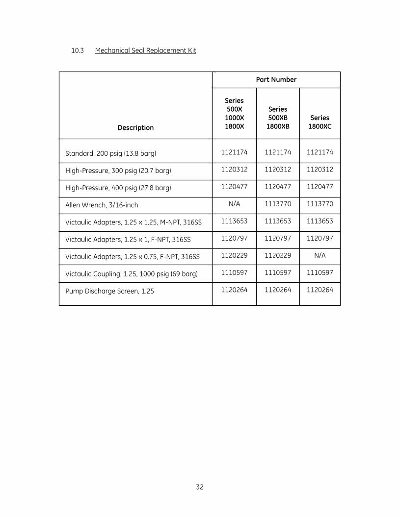
10.3 Mechanical Seal Replacement Kit
32
Description
Standard, 200 psig (13.8 barg)
High-Pressure, 300 psig (20.7 barg)
High-Pressure, 400 psig (27.8 barg)
Allen Wrench, 3/16-inch
Victaulic Adapters, 1.25 x 1.25, M-NPT, 316SS
Victaulic Adapters, 1.25 x 1, F-NPT, 316SS
Victaulic Adapters, 1.25 x 0.75, F-NPT, 316SS
Victaulic Coupling, 1.25, 1000 psig (69 barg)
Pump Discharge Screen, 1.25
Series500XB
1800XB
1121174
1120312
1120477
1113770
1113653
1120797
1120229
1110597
1120264
Series500X
1000X1800X
1121174
1120312
1120477
N/A
1113653
1120797
1120229
1110597
1120264
Series1800XC
1121174
1120312
1120477
1113770
1113653
1120797
N/A
1110597
1120264
Part Number

11.0 ORDERING PARTS
Order parts through your local distributor or directly from:
GE InfrastructureWater & Process Technologies5951 Clearwater DriveMinnetonka, MN 55343-8995 USA
Phone (952) 933-2277Fax: (952) 933-0141Toll Free (800) 848-1750
To order parts, the following information is necessary:
1. Pump model number
2. Pump serial number (from nameplate)
3. Other nameplate information such as operating temperature or material code, andtype of mechanical seal
4. Motor horsepower, motor frame size and enclosure specifications
5. Part name
6. Part number
7. Quantity desired
8. Special materials of construction, if any.
33

12.0 WARRANTY
TONKAFLO PUMP WARRANTY
GE warrants its pumps to be free from defects in design, material, or workmanship for a peri-od of 15 months from receipt or 12 months from installation of the product, whichever occursfirst, when said products are operated in accordance with written instructions and areinstalled properly. If Tonkaflo pumps are altered or repaired without prior approval of GE, allwarranties are void. If any defects or malperformance occur during the warranty period, GE’ssole obligation shall be limited to alteration, repair or replacement at GE's expense, freight onboard (F.O.B.) factory, of parts or equipment which, upon return to GE and upon GE’s exami-nation, prove to be defective. Equipment and accessories not manufactured by GE are war-ranted only to the extent of and by the original manufacturer's warranty. GE shall not beliable for damage or wear to equipment caused by abnormal conditions, excessive temper-atures, vibration, failure to properly prime or to operate equipment without flow, or causedby corrosives, abrasives or foreign objects. The foregoing warranty is exclusive and in lieu ofall other warranties, whether expressed or implied including any warranty of merchantabili-ty or fitness for any particular purpose. In no event shall GE be liable for consequential orincidental damages.
34
Pump Model Number:
Pump Serial Number:
P/N 1125857 Rev B


For more information call 952-933-2277 or 800-848-1750 in the U.S., or visit www.gewater.com.
© 2004, General Electric Company. All rights reserved.P/N 1125857 Rev. B
North American Sales Euro/Africa Sales Asia/Pacific Sales5951 Clearwater Drive 230 rue Robert Schurman 1044/8 SOI 44/2Minnetonka, MN ZA des Uselles Sukhumvit Road Parkanog55343-8995 77350 Le Mée sur Seine Bangkok 10110USA FRANCE THAILAND(952) 933-2277 Phone +33 1 64 10 2000 Phone + 66 2 38 14213 Phone(952) 933-0141 Fax +33 1 64 10 3747 Fax + 66 2 39 18183 Fax
GE InfrastructureWater & Process Technologies