Embed Size (px)
Citation preview

OSW Doc. 530-R-94-012NTIS No. PB94-170255
INNOVATIVE METHODS OF MANAGINGENVIRONMENTAL RELEASES
AT MINE SITES
April 1994
U.S. Environmental Protection AgencyOffice of Solid WasteSpecial Wastes Branch401 M Street, S.W.
Washington, D.C. 20460
Innovative Methods of Managing Environmental Releases at Mine Sites
i
DISCLAIMER AND ACKNOWLEDGEMENTS
This document was prepared by the U.S. Environmental Protection Agency(EPA).
The mention of company or product names is not to be considered anendorsement by the U.S. Government or the U.S. Environmental ProtectionAgency (EPA).
Innovative Methods of Managing Environmental Releases at Mine Sites
ii
TABLE OF CONTENTS
Page1.0 INTRODUCTION . . . . . . . . . . . . . . . . . . . . . . . . . . . . . . . . . . . . . . . . . . . . . . . . . . . . . . . . . . . . . . . . . . . 1
2.0 SOURCE REDUCTION . . . . . . . . . . . . . . . . . . . . . . . . . . . . . . . . . . . . . . . . . . . . . . . . . . . . . . . . . . . . . 2 2.1 FLOTATION PROCESS CONTROL . . . . . . . . . . . . . . . . . . . . . . . . . . . . . . . . . . . . . . . . . . . 2
2.2 PYRITE FLOTATION . . . . . . . . . . . . . . . . . . . . . . . . . . . . . . . . . . . . . . . . . . . . . . . . . . . . . . . . 132.3 METAL CLEANING TECHNOLOGY . . . . . . . . . . . . . . . . . . . . . . . . . . . . . . . . . . . . . . . . . . 21
3.0 RECYCLING . . . . . . . . . . . . . . . . . . . . . . . . . . . . . . . . . . . . . . . . . . . . . . . . . . . . . . . . . . . . . . . . . . . . . . 253.1 SLAG REPROCESSING . . . . . . . . . . . . . . . . . . . . . . . . . . . . . . . . . . . . . . . . . . . . . . . . . . . . . . 253.2 TAILINGS REPROCESSING OPERATION . . . . . . . . . . . . . . . . . . . . . . . . . . . . . . . . . . . . . . 343.3 PIPE RECYCLING/REUSE . . . . . . . . . . . . . . . . . . . . . . . . . . . . . . . . . . . . . . . . . . . . . . . . . . . 423.4 RECYCLING MINE TIRES . . . . . . . . . . . . . . . . . . . . . . . . . . . . . . . . . . . . . . . . . . . . . . . . . . . 54
4.0 OTHER PRACTICES . . . . . . . . . . . . . . . . . . . . . . . . . . . . . . . . . . . . . . . . . . . . . . . . . . . . . . . . . . . . . . . 644.1 WATER MANAGEMENT AT MINE SITES . . . . . . . . . . . . . . . . . . . . . . . . . . . . . . . . . . . . . 644.2 CYPRUS BAGDAD POLLUTION PREVENTION PLAN . . . . . . . . . . . . . . . . . . . . . . . . . . . 83
Innovative Methods of Managing Environmental Releases at Mine Sites
iii
LIST OF TABLES
Page
Table 1. List of Measured Variables Monitored by the System at ASARCO's Sweetwater Mill . . . . . . . . . 8Table 2. Copper Values from Slag at San Manuel . . . . . . . . . . . . . . . . . . . . . . . . . . . . . . . . . . . . . . . . . . . . . 26Table 3. IMC Inventory of Pipe In Use or Available, July 1992 . . . . . . . . . . . . . . . . . . . . . . . . . . . . . . . . . 44Table 4. Sizes and Uses of Pipe by IMC . . . . . . . . . . . . . . . . . . . . . . . . . . . . . . . . . . . . . . . . . . . . . . . . . . . . 45Table 5. Size and length of matrix pipelines (September 1992) . . . . . . . . . . . . . . . . . . . . . . . . . . . . . . . . . . 47Table 6. Hayden Hill Control Measures . . . . . . . . . . . . . . . . . . . . . . . . . . . . . . . . . . . . . . . . . . . . . . . . . . . . . 67Table 7. Cyprus Bagdad Control Strategies . . . . . . . . . . . . . . . . . . . . . . . . . . . . . . . . . . . . . . . . . . . . . . . . . . 71Table 8. Costs of Drainage Management Systems for Construction Sites . . . . . . . . . . . . . . . . . . . . . . . . . . 73Table 9. Sediment and Erosion Control Costs . . . . . . . . . . . . . . . . . . . . . . . . . . . . . . . . . . . . . . . . . . . . . . . . 74
LIST OF FIGURES
Page
Figure 1. Doe Run Fletcher Flow Diagram Showing Location of Process Control Measurements . . . . . . . . . . . . . . . . . . . . . . . . . . . . . . . . . . . . . . . . . . . . . . . . . . . . . . . . . . . . . . . . . 5
Figure 2. Fletcher Mill Daily Report . . . . . . . . . . . . . . . . . . . . . . . . . . . . . . . . . . . . . . . . . . . . . . . . . . . . . . . 7Figure 3. Map of the Superior Mine and Mill . . . . . . . . . . . . . . . . . . . . . . . . . . . . . . . . . . . . . . . . . . . . . . . . 13Figure 4. Pyrite Flotation Circuit Flowsheet . . . . . . . . . . . . . . . . . . . . . . . . . . . . . . . . . . . . . . . . . . . . . . . . . 16Figure 5. Location Map . . . . . . . . . . . . . . . . . . . . . . . . . . . . . . . . . . . . . . . . . . . . . . . . . . . . . . . . . . . . . . . . . 25Figure 6. Process Flow Diagram for Slag Cooling. . . . . . . . . . . . . . . . . . . . . . . . . . . . . . . . . . . . . . . . . . . . . 27Figure 7. Flotation Operation Flow Diagram. . . . . . . . . . . . . . . . . . . . . . . . . . . . . . . . . . . . . . . . . . . . . . . . . 28Figure 8. Pinto Valley Miami Unit, Location Map . . . . . . . . . . . . . . . . . . . . . . . . . . . . . . . . . . . . . . . . . . . . 34Figure 9. Pinto Valley Miami Unit, Process Flow Diagram. . . . . . . . . . . . . . . . . . . . . . . . . . . . . . . . . . . . . . 35Figure 10. Pinto Valley Miami Unit, Computer-Controlled Tailings Reprocessing Operation
Instantaneous Flow Rates. . . . . . . . . . . . . . . . . . . . . . . . . . . . . . . . . . . . . . . . . . . . . . . . . . . . . . . . 35Figure 11. Pinto Valley Miami Unit, Copper Cities Deep Pit Well and Seep Locations. . . . . . . . . . . . . . . . 36

Innovative Methods of Managing Environmental Releases at Mine Sites
1
INNOVATIVE METHODS OF MANAGING ENVIRONMENTAL RELEASES AT MINE SITES
1.0 INTRODUCTION
As a National policy, the Environmental Protection Agency (EPA) is integrating the concept of sourcereduction and recycling in many of its activities. Both the Resource Conservation and Recovery Act (RCRA)and the Pollution Prevention Act of 1990 (PPA), encourage the reduction in volume, quantity and toxicity ofwaste. While RCRA focuses primarily on the reduction in volume and/or toxicity of hazardous waste, thePPA encourages maximum possible elimination of all waste through source reduction.
In addition to source reduction and recycling, environmental improvement may come from the development ofnew and innovative ways to manage wastes and prevent releases. Recognizing that unique issues areassociated with the mining industry, such as large volumes of raw materials used and waste generated, EPAhas prepared this report to describe source reduction and recycling practices and innovative techniques forwaste management currently used in mining. Many of these practices may, in addition to their environmentalbenefit, realize significant cost savings. It is EPA's intent to identify these practices and foster technologyand information transfer throughout the mining industry. In addition, the Agency is seeking additional siteswhere new and innovative practices or technologies are currently being implemented. In the Pollution Prevention Act of 1990, Congress defined source reduction as any practice that:
(i) reduces the amount of any hazardous substance, pollutant, or contaminant entering any wastestream or otherwise releases into the environment (including fugitive emissions) prior to recycling,treatment, or disposal; and
(ii) reduces the hazards to public health and the environment associated with the release of suchsubstances, pollutants, or contaminants.
The term includes equipment or technology modifications, process or procedure modifications,reformulation or redesign of products, substitution of raw materials, and improvements inhousekeeping, maintenance, training, or inventory control.
According to the statute, "source reduction does not include any practice that alters the physical, chemical, orbiological characteristics or the volume of a hazardous substance, pollutant, or contaminant through a processor activity which itself is not integral to and necessary for the production of a product or the providing of aservice."
This report is organized into the following sections:
Innovative Methods of Managing Environmental Releases at Mine Sites
2
Source Reduction, Recycling, Other Practices.
In the context of non-coal mining (extraction and beneficiation), source reduction can include process controlto produce a purer product while reducing hazardous constituents in a waste stream (Process Control at DOERun and ASARCO) and production of a new saleable product while reducing hazardous constituents in awaste stream (Pyrite Flotation at Superior Mine). Each of these practices reduces the amount of a hazardoussubstance being released to the environment and is integral to production of a product. Although the overallreduction of hazards to public health and the environment is not easily measured, improvement is at leastincrementally positive in nature. The section on metal parts washing also presents source reductionopportunities.
Recycling opportunities unique to mining include slag reprocessing at San Manual, tailings reprocessing atPinto Valley and pipe recycling at an IMC Phosphate mine in Florida. Recycling opportunities that are moregeneric include used oil burned for energy recovery and tire recycling, although these may have uniqueimplementation considerations at mine sites. The "Other Practices" section addresses topics of a moregeneral nature and includes a description of best management practices for water management and the facilitypollution prevention plan prepared by the Cyprus Baghdad Mine. Each of these practices may present abetter alterative to simple disposal of wastes and, in addition to reducing the threat to human health and theenvironment, may result in substantial cost savings to industry.
In preparing these reports, EPA collected information from site visits to specific facilities, conversations withinterested parties, and from publicly available documents. EPA has not conducted an independentverification of the data. Detailed economic analyses were not obtained due to confidential businessinformation concerns. Each of the subsections of this report were released as separate reports for commentand have been revised accordingly. These reports were first presented to the public at the PollutionPrevention Conference held in Snowmass, Colorado in August, 1993. Two reports initially prepared as partof this effort have not been included in this compendium. EPA found that utilization of used oil in ANFO isnot currently practiced, therefore this report has not been presented here. In addition, a report on the INCOcyanide treatment process was prepared; this report has been integrated into another draft report on treatmentmethods for cyanidation wastes.
To assist with technical questions and issues, a list of technical contacts familiar with each technology isprovided, however, this listing is not to be considered an endorsement by the U.S. Government or the U.S.Environmental Protection Agency (EPA).
2.0 SOURCE REDUCTION
2.1 FLOTATION PROCESS CONTROL
Innovative Methods of Managing Environmental Releases at Mine Sites
3
An automatic process control system can be defined as any arrangement of sensors, computing elements, andcontrol units designed to minimize the difference between the observed and desired behavior of the process inquestion. In general, the operator specifies the desired values of process variables as a set of setpoints, andthe sensors measure the current values of those same variables as a set of numbers describing the state of theprocess. The differences between the setpoints and the current state are known as the variances. Thecomputing elements in the control system attempt to minimize the complete set of errors by altering thepositions of valves, changing the speeds of motors, or manipulating other variables which may affect the stateof the process. Controllers may be as simple as a float valve, which reduces the flow of liquid to a tank as itapproaches the desired level. Alternatively, they may involve a host of sensors feeding information to one ormore computers which interpret the observed state of the system via detailed models before deciding on a setof appropriate responses. Simple control schemes are usually reliable and easy to maintain. However, theycannot provide the sorts of optimum response to plant-wide upsets that are required in process industriestoday. The level of control obtainable from a control scheme is generally related to the level of processknowledge incorporated into its design. This report focuses on the application of relatively advanced processcontrol technology to mineral flotation.
Application to Flotation Mills
Flotation mills separate metalliferous minerals from waste rock (gangue) by causing finely ground mineralparticles to float to the top of a frothing bath of aerated ore slurry. Surfactants are used to cause air bubblesto attach themselves to the valuable minerals, but not to the gangue. Froth from the final stage of a cascadeof floatation cells is dewatered to produce an ore concentrate, which is shipped to a smelter. The goal offlotation mill operators is twofold; they must maximize the amount of material floated to the concentrate,while simultaneously minimizing the concentrate's gangue content. In addition, many of the major resourcesuppliers have stated their intention of improving environmental quality (e.g., The Doe Run Company, 1987). In order to meet this commitment, the mill operators must also minimize the amount of surfactants and heavymetals in the waste stream fed to the tailings pond. Parameters that may be varied in order to achieve thisgoal include the rate of addition of surfactants, the rate of sparging of air into the flotation cells, relativepumping rates of overflow and recycle streams within the cascade, and the particle size distribution in theincoming ore slurry. The problems of control are compounded when the ore contains more than one valuablemineral and each must be separated from the others and from the gangue to form a high-purity concentrate. Reliable on-line measurements of metals content at various points throughout the mill is necessary in order toeffect control of the operation.
X-Ray Fluorescence
X-Ray Fluorescence (XRF) is an analytical technique designed to rapidly measure the metals content of asample. When atoms of the heavier metals are bombarded with X-rays, electrons lying in low orbitals closeto the nucleus may be ejected. Electrons from the outer shells will jump to fill the gaps, emitting radiation inthe form of X-rays. Radiation emitted by electrons in these high-energy transitions is characteristic of theatom and is essentially unaffected by the atom's chemical environment. In a XRF analyzer, the intensities of
Innovative Methods of Managing Environmental Releases at Mine Sites
4
the emitted X-rays are measured by spectrometers coupled to diffracting crystals. One crystal/spectrometerassembly is provided for each metal to be measured. A typical arrangement for an analyzer in a lead-zinc millwould include assemblies for lead, zinc, copper, and iron. Excitation of the sample is provided by an X-raytube incorporated in the analyzer. When slurry samples are to be analyzed, the sample is passed through asample cell. Since fluorescence is a surface phenomenon, the sample cell is designed to induce thoroughmixing so that the average metal content determined over the measuring period is characteristic of the bulksample.
In industrial X-ray analyzers, sample lines are constructed to bring slurry samples from various parts of themill to the analyzer. A sequencer within the analyzer causes the machine to switch from one sample to thenext every 1-2 minutes. The switching may be done by opening valves to feed the desired slurry samplethrough a single sample cell, or by causing the analyzer unit to move along a line of sample cells dependingon the analyzer used. Output from the analyzer is in the form of a digital electronic signal, suitable for inputto a computer. Units of this type are marketed in North America.
Evolving Level of Control
In flotation mills without X-ray analyzers, mill operators typically collect slurry samples from flotation cellsby hand. They then swirl each sample in a pan similar to those used by gold miners to remove the lighterconstituents. Visual inspection of the minerals left behind gives them an indication of the mineral content andthe particle size. Armed with this information, they can manually adjust surfactant addition rates and otherparameters in order to meet their operating goals. This approach to process control has the advantage ofrequiring the operators to become intimately familiar with the characteristics of the ore and the behavior ofthe mill. Over time, the operators collectively become a valuable repository of process information, not all ofwhich can easily be quantified.
In mills with on-line X-ray analyzers, operators can base their responses to process upsets on absolutedeterminations of the metals content of each stream sampled. In the simplest scheme, the operator reads theoutput from the analyzer, which is generally updated every 10-15 minutes, and uses that information togetherwith readings from flowmeters and level gauges in making manual adjustments to valve settings and motorspeeds. Few, if any, mills with X-ray analyzers operate in this manner. In most cases, the operators establishsetpoints for low-level controllers which regulate flowrates and levels as desired. In the next stage ofdevelopment, the low-level control loops are implemented in software by a central process control computer,which also provides a visual display of the state of the mill. This level of control is the focus of this sectionof the report. At the present time, some mills are moving to a more advanced approach in which the centralcomputer uses historical data and/or a detailed model of the total process to establish new setpointsautomatically. This is typically referred to as an expert system. The operator may override the computerwhen necessary, or may alter the process model. The same sequence of developments has occurred in manyother sectors of industry, including power generation, oil refining, and chemical manufacturing.
Innovative Methods of Managing Environmental Releases at Mine Sites
5
A large number of companies market process control hardware and software for a variety of applications. X-ray analyzers can be interfaced with hardware from most of these companies. Some purchasers mayappreciate the possibilities made available by buying components from more than one company. Others mayprefer to purchase an integrated package from a manufacturer that specializes in mining applications.
Review of Current Implementation
Figure 1 shows the main features of the control scheme implemented at the Doe Run Fletcher mill. Thearrangement reflects the mill circuit as of November, 1992. The facility beneficiates a mixed sulfide ore thataverages 5.5% galena (PbS), 1% sphalerite (ZnS), and 0.3% chalcopyrite (CuFeS ). Gangue minerals include2
dolomite, calcite, pyrite, and marcasite. The ore is extracted by underground mining, and lead content mayvary by 50% over a short period of time. The mill has only one ore feed from the mine to the grinding circuit,providing limited buffering of variations in mine output. The flotation system must therefore be capable ofadjusting rapidly to cope with substantial changes in feed composition.
Coarsely crushed ore from the underground primary crusher is stored in a single ore bin on the surface. Orefrom the bin is fed to a secondary cone crusher. The temperature inside the crusher, the pressure on the cone,oil pressure, and electric power consumption are monitored to ensure that it is operating within its mechanicallimits. Crushed ore is fed to a rod mill, together with water and flotation reagents. The flotation reagentsintroduced at this point are a xanthate collector to float sulfide minerals, zinc sulfate (ZnSO ) to depress4
sphalerite (ZnS), and sodium cyanide (NaCN) to depress pyrite (FeS). The rate of addition of thesecomponents is monitored by flowmeters on each line and controlled by pneumatically driven valves. Eachvalve is connected to a pressure/current (P/I) converter, which receives a 4-20 mA analog signal from theprocess control computer. Output from the rod mill goes to a cyclone. Oversize material falling through thecyclone is reground in a ball mill. Material leaving the grinding circuit averages 53% <200 mesh. Thisstream passes through a nuclear density gauge and a particle size monitor before entering the first flotationunit. A sample of this slurry is drawn off every 10 minutes and fed automatically to a XRF analyzer.
The feed slurry is fed together with a frothing agent to the lead rougher cells. Air is sparged into the cellsfrom below. The lead rougher consists of two sets of three cells; each set has its own pulp level control. Ineach of the two control loops, pulp level is monitored by a float. The position of this float is input to a simpleProportional-Integral-Derivative (PID) controller, which adjusts the position of a dart valve within the cells. The tailings stream leaving the lead rougher is assayed by the XRF analyzer. The froth collected in thelaunder is fed to a lead cleaner and recleaner cells. The cleaner is equipped with pulp level control, but therecleaner is not (pulp level control is to be added to the recleaner in the future). Tailings from the cleaner arerecycled to the rougher.
Overflow from the recleaner launder is piped to a lead-copper absorber unit. Sulfur dioxide, starch, andcaustic soda are added at this stage to depress the floatation of galena while allowing the chalcopyrite to floatin the copper circuit. The copper circuit is run as warranted to separate chalcopyrite from galena. Slurryleaving the absorber is fed to the copper rougher. Overflow from this unit is piped to the copper cleaner and
Innovative Methods of Managing Environmental Releases at Mine Sites
6
thence to the recleaner. Each of these units has automatic pulp level control. Sodium dichromate is addedbetween the cleaner and recleaner to depress galena. The tailings stream from the copper rougher is assayedby the XRF analyzer before entering the lead thickener. In the thickener, the suspended solids settle out toform a lead concentrate. A level indicator and a torque indicator are mounted on the shaft of the thickenerrake. The level indicator gives some indication of the depth of settled material and the torque indicatorprovides warning should the rake begin to seize. The lead concentrate is dewatered on a rotary vacuum filter. Filter cake is collected in a bin which is mounted on a load cell. Froth leaving the copper recleaner issimilarly thickened and dewatered to produce copper concentrate.
The zinc flotation circuit is fed by tailings from the lead rougher. Ammoniated cupric chloride is added toactivate the previously depressed sphalerite before the slurry enters the zinc rougher. Frothing agent andadditional collector are also added at this point. Tailings from the rougher are assayed by XRF and pumpedto the tailings pond. The zinc circuit differs from the other two circuits in that cleaning is performed by a pairof air-sparged column cells. Differential pressure is measured at three levels within each of the cells. The pHis monitored on the first column. Lime may be added to the rougher launder if the pH is too low. Froth fromthe second column is assayed before being thickened and dewatered to form zinc concentrate. Copper andzinc concentrates are produced using the same filter. Since copper is a minor constituent of the ore, the filteris devoted to zinc concentrate production for most of its operating hours.
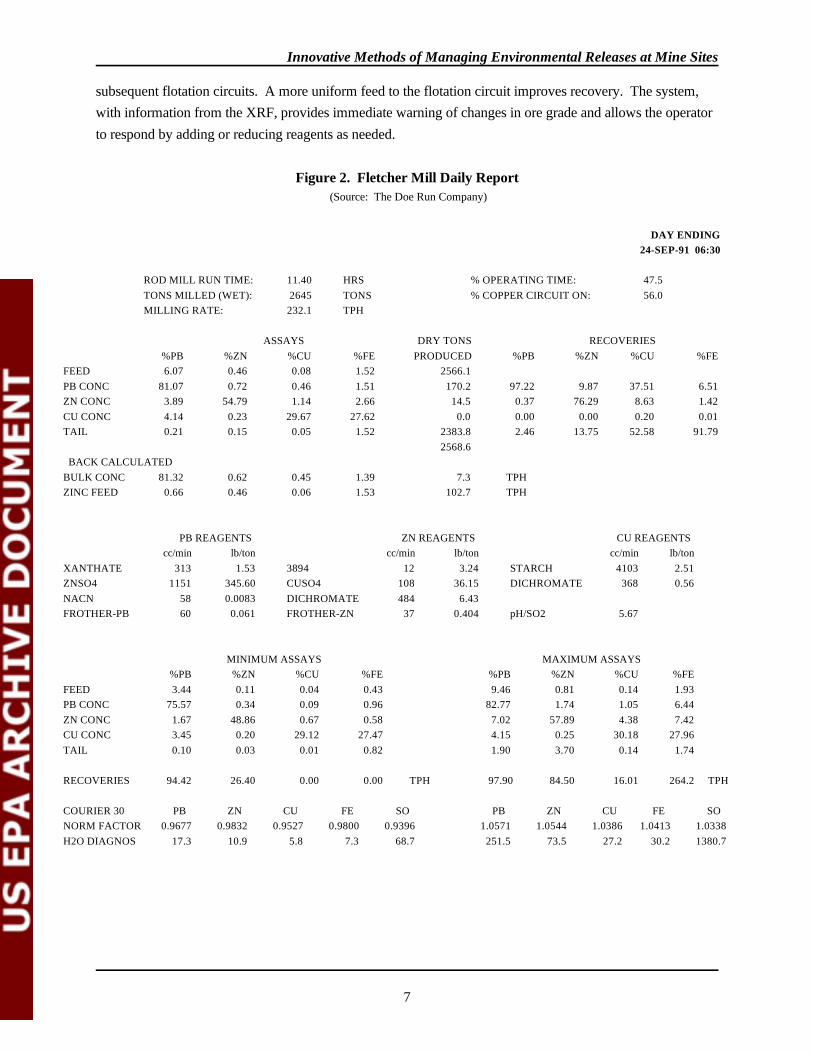
Assay data from the XRF unit is sent to a process control computer. Flowmeter readings from all of thereagent addition lines are also sent to the computer, as are the outputs from the particle size monitor on thegrinding circuit, the pH meter on the zinc circuit, outputs from the thickener level and torque indicators, andthe concentrate bin load cells. The computer also receives signals representing the position of the valves oneach reagent line. The computer displays most of this data on an operator console in the mill control room. Based on the data presented, the operator can vary the reagent addition rates to try to obtain a betterseparation among the minerals. Warnings of abnormal conditions are also displayed on the console. Anexample of the computer printout for the Fletcher mill from September 23, 1991, is presented in Figure 2. The report shows recoveries of lead and zinc from the ore feed to be 97.22 percent, and 76.29 percent,respectively. Because of the low copper content in the feed assays, the copper circuit was not running on thisday. The computer system maintains an archive of the systems's state as a function of time. Electric motors,including those on pumps and blowers throughout the mill, are controlled by a motor control center. Withappropriate controller cards, the computer could also be used to control the speeds of some of these motors. Where the historical behavior of the mill has been recorded and analyzed, mill managers can specify empiricalformulae relating reagent needs to assay results.
The ASARCO Sweetwater mine extracts a lead/zinc/copper ore similar to Fletcher's mine. The mill currentlybeneficiates only lead and zinc minerals, but is planning to add a copper circuit in the near future (the oreaverages 0.3 to 0.4 percent copper). The mill through put is 290 tons per hour nominally, and operates fourdays per week. The Sweetwater mill has two fine ore bins. Each bin has three feed hoppers from which themill selects ore. This ability gives the operator more control in preparing a uniform feed to the grinding and
Innovative Methods of Managing Environmental Releases at Mine Sites
7
subsequent flotation circuits. A more uniform feed to the flotation circuit improves recovery. The system,with information from the XRF, provides immediate warning of changes in ore grade and allows the operatorto respond by adding or reducing reagents as needed.
Figure 2. Fletcher Mill Daily Report(Source: The Doe Run Company)
DAY ENDING24-SEP-91 06:30
ROD MILL RUN TIME: 11.40 HRS % OPERATING TIME: 47.5TONS MILLED (WET): 2645 TONS % COPPER CIRCUIT ON: 56.0MILLING RATE: 232.1 TPH
ASSAYS DRY TONS RECOVERIES%PB %ZN %CU %FE PRODUCED %PB %ZN %CU %FE
FEED 6.07 0.46 0.08 1.52 2566.1PB CONC 81.07 0.72 0.46 1.51 170.2 97.22 9.87 37.51 6.51ZN CONC 3.89 54.79 1.14 2.66 14.5 0.37 76.29 8.63 1.42CU CONC 4.14 0.23 29.67 27.62 0.0 0.00 0.00 0.20 0.01TAIL 0.21 0.15 0.05 1.52 2383.8 2.46 13.75 52.58 91.79
2568.6 BACK CALCULATEDBULK CONC 81.32 0.62 0.45 1.39 7.3 TPH ZINC FEED 0.66 0.46 0.06 1.53 102.7 TPH
PB REAGENTS ZN REAGENTS CU REAGENTS cc/min lb/ton cc/min lb/ton cc/min lb/ton
XANTHATE 313 1.53 3894 12 3.24 STARCH 4103 2.51ZNSO4 1151 345.60 CUSO4 108 36.15 DICHROMATE 368 0.56NACN 58 0.0083 DICHROMATE 484 6.43FROTHER-PB 60 0.061 FROTHER-ZN 37 0.404 pH/SO2 5.67
MINIMUM ASSAYS MAXIMUM ASSAYS%PB %ZN %CU %FE %PB %ZN %CU %FE
FEED 3.44 0.11 0.04 0.43 9.46 0.81 0.14 1.93PB CONC 75.57 0.34 0.09 0.96 82.77 1.74 1.05 6.44ZN CONC 1.67 48.86 0.67 0.58 7.02 57.89 4.38 7.42CU CONC 3.45 0.20 29.12 27.47 4.15 0.25 30.18 27.96TAIL 0.10 0.03 0.01 0.82 1.90 3.70 0.14 1.74
RECOVERIES 94.42 26.40 0.00 0.00 TPH 97.90 84.50 16.01 264.2 TPH
COURIER 30 PB ZN CU FE SO PB ZN CU FE SO NORM FACTOR 0.9677 0.9832 0.9527 0.9800 0.9396 1.0571 1.0544 1.0386 1.0413 1.0338H2O DIAGNOS 17.3 10.9 5.8 7.3 68.7 251.5 73.5 27.2 30.2 1380.7
Innovative Methods of Managing Environmental Releases at Mine Sites
8
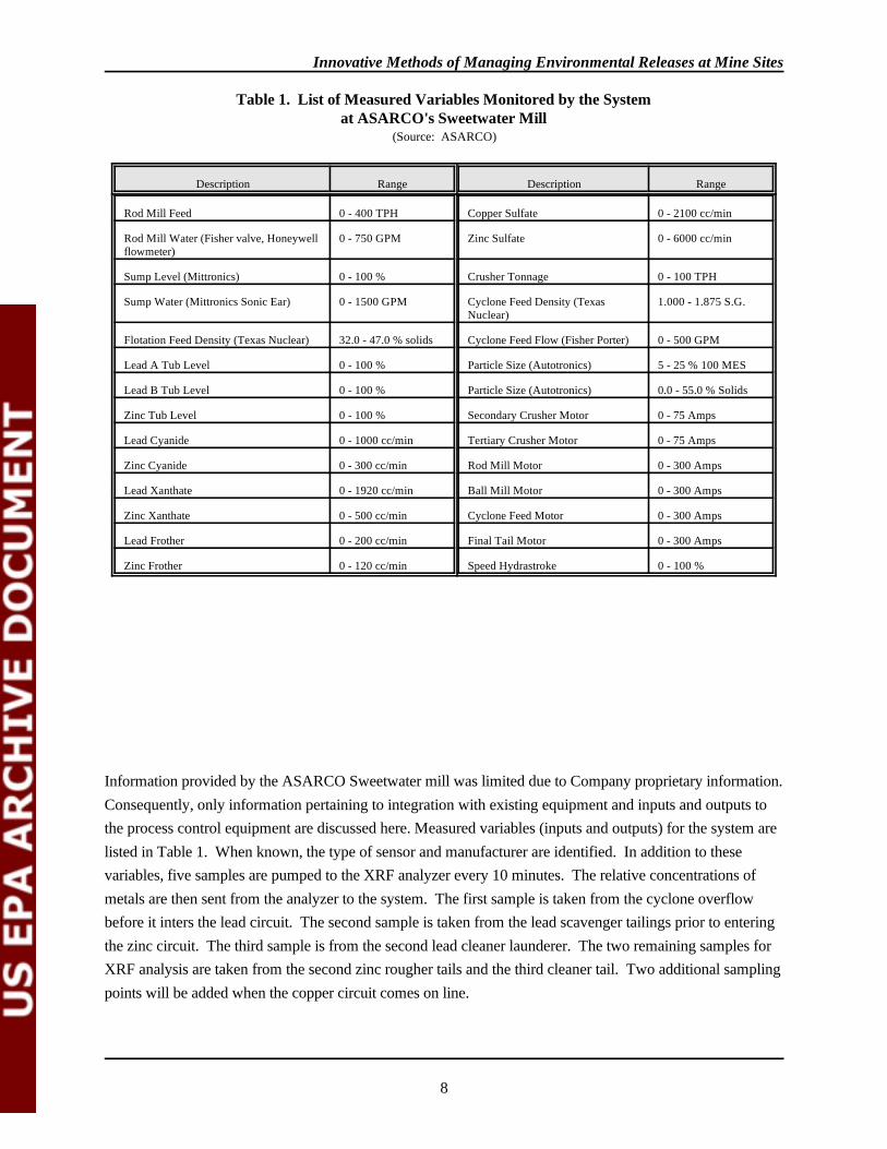
(Source: ASARCO)
Description Range Description Range
Rod Mill Feed 0 - 400 TPH Copper Sulfate 0 - 2100 cc/min
Rod Mill Water (Fisher valve, Honeywellflowmeter)
0 - 750 GPM Zinc Sulfate 0 - 6000 cc/min
Sump Level (Mittronics) 0 - 100 % Crusher Tonnage 0 - 100 TPH
Sump Water (Mittronics Sonic Ear) 0 - 1500 GPM Cyclone Feed Density (TexasNuclear)
1.000 - 1.875 S.G.
Flotation Feed Density (Texas Nuclear) 32.0 - 47.0 % solids Cyclone Feed Flow (Fisher Porter) 0 - 500 GPM
Lead A Tub Level 0 - 100 % Particle Size (Autotronics) 5 - 25 % 100 MES
Lead B Tub Level 0 - 100 % Particle Size (Autotronics) 0.0 - 55.0 % Solids
Zinc Tub Level 0 - 100 % Secondary Crusher Motor 0 - 75 Amps
Lead Cyanide 0 - 1000 cc/min Tertiary Crusher Motor 0 - 75 Amps
Zinc Cyanide 0 - 300 cc/min Rod Mill Motor 0 - 300 Amps
Lead Xanthate 0 - 1920 cc/min Ball Mill Motor 0 - 300 Amps
Zinc Xanthate 0 - 500 cc/min Cyclone Feed Motor 0 - 300 Amps
Lead Frother 0 - 200 cc/min Final Tail Motor 0 - 300 Amps
Zinc Frother 0 - 120 cc/min Speed Hydrastroke 0 - 100 %
Table 1. List of Measured Variables Monitored by the Systemat ASARCO's Sweetwater Mill
Information provided by the ASARCO Sweetwater mill was limited due to Company proprietary information. Consequently, only information pertaining to integration with existing equipment and inputs and outputs tothe process control equipment are discussed here. Measured variables (inputs and outputs) for the system arelisted in Table 1. When known, the type of sensor and manufacturer are identified. In addition to thesevariables, five samples are pumped to the XRF analyzer every 10 minutes. The relative concentrations ofmetals are then sent from the analyzer to the system. The first sample is taken from the cyclone overflowbefore it inters the lead circuit. The second sample is taken from the lead scavenger tailings prior to enteringthe zinc circuit. The third sample is from the second lead cleaner launderer. The two remaining samples forXRF analysis are taken from the second zinc rougher tails and the third cleaner tail. Two additional samplingpoints will be added when the copper circuit comes on line.
Innovative Methods of Managing Environmental Releases at Mine Sites
9
Operational Requirements
Use of an on-line X-ray analyzer coupled with a process control computer greatly simplifies the operation of amill. One mill required 24 operators, 3 engineers, and 3 supervisors before this technology was introduced. It now requires about 8 staff to operate. Some additional skills are needed to use the new technologyeffectively. The mill managers should have some familiarity with the basic concepts of computerprogramming in order to be able to customize the software to their best advantage. The XRF unit is veryreliable. From time to time, X-ray tubes will degrade and must be replaced. The mill will need to stock avariety of spare parts for sensors and control elements. Most of the electronic signals both to and from thecomputer are in analog form, and maintenance of the wiring will not present any difficulty to an industrialinstrument technician.
Costs and Benefits
Benefits associated with process control technology may include the following: 1) a decrease in reagentconsumption as a result of rapid response in reagent addition rates in accordance with mill feed grade andthroughput fluctuations; 2) a stabilized process resulting in increases in the amount of lead and zincproduced through higher metal recoveries (constrained by concentrate grade); and 3) more effective grindingcontrol which would allow an increase in mill tonnage throughput (Jones 1991, Heitman, undated). Thereduced use of reagents is viewed as an environmental benefit. Further, since more metal is recovered usingthis system the ratio of waste to final product has been reduced.
Installation
Purchase and installation of the process control system for the Fletcher mill cost approximately $600,000 in1989. Only a limited amount of additional money was spent on training because many of the staff hadalready worked with the system at the Buick mill. The actual installation was completed by Doe Runpersonnel.
Integration with Existing Facility
The process control system at the Fletcher facility was installed between 1989 and 1990. The Doe RunCompany had gained experience with the use of X-ray analyzers and process control at their Buick millfacility. The Buick mill installed a computerized process control system in 1981, using a XRF unit and acomputer system. Construction of the control system at Buick required much time and effort. Once theBuick system was completed, transferral of the technology to the Fletcher mill was relatively straightforward.
Operational Requirements
Prior to the installation of the control system, operation of the mill required 3 operators and 1 supervisor pershift. Currently they are using 2 operators and 1 supervisor per shift. The reduction in staff needs was much
Innovative Methods of Managing Environmental Releases at Mine Sites
10
more dramatic at Buick, where the mill is larger. Other requirements, such as energy, are negligible. DoeRun maintains a stock of parts for all their mill facilities on the Trend totaling $200,000 to respond toequipment failures. Most of these are sensor parts; the balance are X-ray tubes and computer equipment.
Benefits
The new control system has allowed Doe Run to obtain a better separation of metalliferous minerals fromgangue. This means, in principle, that lesser amounts of gangue and other wastes are being sent to thesmelter. There is also a slight reduction in the average metal load disposed of in the tailings impoundment. From the operators' point of view, the new system has made it easier to respond smoothly to sudden changesin ore grade. The main benefit perceived by the company is an economic one: the metal concentrates are ofhigher purity than they were before the mill was modernized. Costs savings are summarized as follows:
• Reduced reagent costs by 14 percent per year, saving $75,000,• Improved lead metallurgy by $100,000 per year,• Improved zinc metallurgy by $330,000 per year,• Improved copper metallurgy by $270,000 per year.
These amount to a total annual savings of $785,000 (Jones 1991). Savings in labor costs were not identified.
Waste Reduction
Use of the control system has resulted in production of higher quality concentrates being sent to the smelter. Thus, by reducing the gangue content of the final concentrate, the volume of slag generated at the smelter isreduced. In addition, Doe Run estimates that the metal concentration in the tailings waste stream was 0.2percent before the process control system was installed. The average metal concentration in the tailings nowis 0.15 percent. This amounts to a reduction of 4,500 to 5,000 pounds of metal entering the tailings pond perday.
Limitations
The use of on-line XRF analysis and computerized process control will not necessarily solve all of a mill'scontrol problems. The XRF unit determines the total content of each metal in a stream. In some cases, thesame metal may be present as two different minerals which behave differently in the flotation cells. Such asituation could occur in copper mines, where both sulfide and oxide ores are encountered. It may benecessary to use another type of probe to obtain additional information about the feed before determining therequired dosage of reagents.
Future trends in flotation mill control seem to be in the direction of incorporating more and more of the millfunctions into a centralized control scheme and toward the use of expert systems. Many mill owners whohave invested in a centralized control system initially configured it to control reagent addition rates based on
Innovative Methods of Managing Environmental Releases at Mine Sites
11
XRF assay data. These are the most critical parameters affecting the flotation process. Some of these ownersare now planning to add additional control loops, for example, motor speed control and pulp level control totheir process control system.
For mill owners who have built up an archive of operating data, the use of an expert system may offer newpossibilities. An expert system is a software tool that can be interfaced with the mill control software. Basedupon analysis of historical operator responses to changes in the behavior of the mill, the expert system canpropose a set of responses to a new situation. The operator can then choose to accept the system's judgementor try an alternative course of action. Over time, the system builds an increasingly reliable empirical model ofthe process in the form of rules and equations. In theory, the system should allow novice operators to benefitfrom all of the accumulated wisdom of their colleagues. However, effective use of an expert system requiresa commitment on the part of both mill managers and operators to work with the system on a regular basisuntil it has been "trained" sufficiently.
Conclusions
Process control is applicable and probably advantageous to many milling systems requiring continuousmonitoring. The benefits include better information, and thus control of a mill, depending on the level ofinstrumentation available. Examples presented here relate specifically to flotation of lead/zinc/copper ores. Different sensors may be more suitable for monitoring other mill systems. Process control equipment isparticularly well suited to underground mines where the ore grade received by the mill is variable. On-linemonitoring of mill feed allows quick, and in some cases instantaneous, response to changing feed grades. In asimple cost/benefit analysis, the facilities visited to prepare this report suggest that payoff can occur quicklywith increased concentrate quality and reduced reagent consumption.
Environmental benefits can also be realized. While the metal load to the tailings impoundment was reducedin one of the facilities visited, the reduction was marginal compared to the total volume generated per unittime. Greater reductions in wastes are seen at the smelter, where a higher purity concentrate generates lesswaste in the form of slag. Also, the reduction in reagent usage is significant and has its own benefits in theform of costs savings and a reduction in the total waste stream either to the tailings impoundment or thesmelter. The facilities visited contend that the reagents stay with the concentrate (adhering to the mineralsurfaces) and do not generally end up in the tailings impoundment.
Contacts
The Doe Run CompanyJohn CarterEnvironmental Manager(314) 244-8152
Terry PerkinsMills and Metallurgy Manager(314) 244-8612

Innovative Methods of Managing Environmental Releases at Mine Sites
12
ASARCOAaron MillerEnvironmental Engineer(314) 924-2222
Brian McKeeverMill Manager(314) 924-2222
References
Jones, James A., Robert D. Deister II, Charles W. Hill, Derek R. Barker and Patrick B. Crummie, December 1991. Process Control at Doe Run's Fletcher Concentrator. Mining Engineering, Vol. 43, Number 12,pages 1407-1411.
Heitman, David A., Undated. Development and Installation of the Buick Concentrator Process Control System. Preparedby AMAX Lead Company of Missouri, Boss Missouri.
The Doe Run Company, 1987. (untitled brochure describing lead production activities). The Doe Run Company, St.Louis, Missouri.
EPA Response to Comments
The Doe Run Company submitted comments on this report, requesting minor editorial changes. EPAresponded to these comments and revised the report.
The U.S. Bureau of Mines submitted comments, which have been addressed as appropriate.

Innovative Methods of Managing Environmental Releases at Mine Sites
Reported for the years 1980-1982, when Superior was1
operating. The average is the weighted average grade of oremilled, based generally on an assay of total copper.
13
2.2 PYRITE FLOTATION
At the Superior Mine in Superior, Arizona (Figure 3), Magma Copper Company is currently producing a highgrade pyrite product by subjecting copper tailings to an additional flotation circuit. Instead of generating atailings high in sulfide, the facility produces less reactive tailings and two products, a fine micronized pyrite(99% iron disulfide) and a coarse pyrite concentrate (45 - 47% iron and 48 - 50 % sulfur). The pyriteproducts are packaged and sold for a variety of uses.
The ore body is a vein deposit, and according to facility personnel, has one of the highest copperconcentrations of any ore mined. The ore body is unique, with total copper concentrations of 4.32 to 4.48percent, compared to other copper mines in Arizona where the total copper concentration average is 0.58percent for the same time period (Arizona Department of Mines and Mineral Resources 1990). Another1
factor making the ore body unique is its pyrite content. Most copper operations are typically mining ore withup to 5 percent pyrite; on the other hand, the Superior ore body has as much as 25 percent pyrite. Accordingto facility personnel, the ore has little or no impurities which also contributes to its uniqueness. Specifically,the ore is high in pyrite (FeS ) with little or no arsenopyrite (FeAsS) and unusually low concentrations of2
heavy metals other than copper. This allows a high quality pyrite product to be produced containing little orno undesirable heavy metals. Mining was conducted at the facility from 1912 until 1982 when the mill and mine shut down due todepressed copper prices. The mine was reopened in 1990. Current underground mining uses the undercutand fill method and is conducted at the 3400 - 4200 levels. Present production is 1000 tons of ore per daywhich yields 50,000 tons of concentrate per year. From this, approximately 15,000 tons of copper isproduced annually. The volume of pyrite produced was not available. Gold and silver by-products are alsoproduced from the Superior Mine operations (6300 and 275,000 ounces, respectively) (Magma Undated).
Figure 3. Map of the Superior Mine and MillSource: Geologic Map of Superior Mining Area, Arizona
Arizona Bureau of Mines, 1943
General Description
In 1986, while the mine remained shut down, Magma started a unique pyrite flotation circuit using existingequipment to remove pyrite from tailings at the site. In August of 1990, the mine re-opened and the operationre-started copper production. At this time, the feed to the pyrite flotation was changed from old tailings to thenewly generated tailings as they exit the copper flotation circuit, with no other operational changes in thepyrite flotation operation. In either case, this operation served to recover as a saleable product, a material(pyrite) typically discharged as a component of waste. Currently, the operation of pyrite flotation is demand

Innovative Methods of Managing Environmental Releases at Mine Sites
Represents an estimate of the productive capacity of2
primary recoverable copper in concentrates, precipitates andcathodes based on historic production figures and capacity ofconcentrator. Does not represent smelter or refinery capacity.
14
driven, with the pyrite circuit used only as needed to meet the demand for the pyrite product. At other times,the pyrite is discharged with the tailings to the tailings impoundment.
Magma produces pyrite in two sizes. The coarse pyrite product (+200 mesh) is sold in 50, 100, and 200pound bags for use in the steel and glass industries. The fine, micronized pyrite is pulverized to 50 percentpassing 2.34 microns and sold for use in the manufacture of grinding wheels. At times, pyrite is also sold inbulk form.
Pyrite, (FeS ) easily oxidizes to form sulfuric acid and, at many mine sites, is associated with acid generation2
from tailings piles and other mining activities. Removing the pyrite prior to discharging the tailings willdecrease the potential for acid generation from tailings, which may in turn, minimize possible waste treatmentand remediation costs. These activities can be conducted while generating additional income for the facility. Because this facility is currently operating the pyrite flotation circuit on an as needed basis to supply demand,pyrite-bearing tailings are discharged periodically to the tailings impoundment. A description of the technicalaspects of the pyrite flotation operation is provided below.
Pyrite Flotation and Drying
The pyrite flotation operation at Superior uses pre-existing equipment. The system manipulates the pH of anormal copper flotation operation in order to float pyrite. After first adding collectors and frothers andraising the pH to depress pyrite and to concentrate copper (typical practice), Magma adds sulfuric acid todrop the pH of the copper tailings, making the pyrite float. According to facility personnel, the tailingsgenerated after pyrite flotation are primarily hematite. Using existing equipment idle during the millshutdown, Magma purchased little new equipment other than a holoflight furnace for drying the pyriteconcentrate. The same operation was used to float both the old tailings and to float tailings currently beinggenerated. Presented below is a detailed description of the flotation operation in the context of currentoperating procedures.
Ore is mined underground and then brought to the surface for processing. The ore is crushed and ground to70 percent passing 200 mesh and sent for initial copper flotation. The copper froth flotation circuit is similarto that used at most other copper flotation facilities, with both rougher and scavenger circuits. The Superioroperation uses Minerec (M200) as the collector and MIBC as the frother. The equipment used for this initialcopper flotation consists of standard froth flotation cells installed at the facility in the 1970s. The estimatedcapacity of the Superior copper operation is 42,000 short tons of recoverable copper per year . Available2
data from 1980 and 1981 set copper recovery efficiencies at approximately 95% and 93% respectively(Arizona Department of Mines and Mineral Resources 1990). Data on current copper recovery efficienciesand the number of flotation cells in use for copper were not obtained.
Innovative Methods of Managing Environmental Releases at Mine Sites
15
The tailings from the scavenger copper flotation circuit are discharged to a cyclone where sands are separatedfrom slimes. When the pyrite flotation is not operating, the copper tailings sands go to the underground minearea and the tailings slimes are discharged to the tailings impoundment. When the pyrite flotation is inoperation, the tailings sands, which are the underflow of the cyclone, go to the pyrite flotation circuit.
The pyrite flotation circuit is similar to the copper flotation circuit and uses existing flotation equipment,which was available due to over capacity of the mill compared to the current rate of mining. To producepyrite concentrate, Magma introduces the copper tailings sands into standard flotation cells, adding water,additional flotation reagents (the same reagents used in the copper flotation circuit) and sulfuric acid (SeeFigure 4). The sulfuric acid causes the pH of the copper tailings to drop from the pH of 11 or 12 used forcopper flotation to a pH of 5.5. At pH 11, pyrite is depressed and does not float, making concentration of thecopper possible; however, as the pH drops below 9, pyrite begins to float. At pH 5.5, pyrite is no longerdepressed and floats in a manner similar to copper. In the pyrite flotation operation, Magma uses seven 100-cubic foot flotation cells in the rougher circuit and two 50-cubic foot flotation cells in the cleaner circuit. According to facility personnel, the rougher circuit discharges tailings for disposal and provides a pyriteconcentrate product with 48 to 50 percent sulfur. The pyrite flotation tailings are primarily hematite althoughspecific constituent analysis was not obtained. Adding the cleaner circuit produces a pyrite concentrate of 99percent purity, with underflow or tailings from the cleaner circuit directed back to the rougher circuit foradditional flotation. The pyrite removal efficiency of the flotation circuits was not obtained.
Once pyrite concentrate exits the flotation circuit, it is pumped to a settling pond for dewatering. Retentiontime for concentrate in the pond was not determined. As the pyrite dries, it is excavated from the pond andsent to the plant, where it is dried, sized, and bagged for sale. Equipment at the plant reflects the only capitalexpenditure for this project, with the purchase of a "used" holoflight dryer, "used" bagging equipment, anddesign and development of pulverizing equipment. The holoflight dryer, where a large internal screw pullsmaterial through a heated compartment, dries the concentrate to four percent water content. The coarse pyriteconcentrate product, separated from the fines by screening, is immediately bagged for sale while additionalgrinding takes place to produce the fine concentrate product. The fine concentrate is produced by pulverizingor "micronizing" the finer particles to 50 percent passing 2.34 microns, with the overall size specificationrange of 1.9 to 3.1 microns. This material is sorted and bagged, with special care taken to avoid the additionof moisture. At this grain size, pyrite is a hazardous material because it is flammable and will ignite with theaddition of moisture. Specific details on the micronizing operation were withheld due to confidential businessinformation concerns.
The coarse pyrite products are bagged in 50, 100 or 200 pound bags and in some cases coarse pyrite is soldin bulk form where the pyrite is loaded directly onto the customer's truck. Fine pyrite product is containerizedunder special conditions (due to flammability) into 30-gallon drums.
The copper flotation circuit operates on a 10 and 4 schedule (10 days on, 4 days off) with maintenanceconducted while the mill is down. Operation of the pyrite circuit is dependent on product demand; thespecific operating frequency was not obtained. Drying and bagging the pyrite concentrate typically occurs 5
Innovative Methods of Managing Environmental Releases at Mine Sites
16
days per week with overtime during the wet season due to the increased drying time necessitated by weatherconditions. Magma sells a total of approximately 500 tons of pyrite concentrate per month. The majority ofthe pyrite product is sold through a broker.
Costs
Magma initiated the pyrite flotation project using existing flotation equipment and limited capital investmentin a "used" dryer and bagging system. The only new equipment purchased was that used for "micronizing,"sorting and packaging the fine concentrate product. Details on capital and operational cost, as well asrevenues, were withheld due to confidential business information concerns on the part of Magma; however,the existing equipment and characteristics of the ore and available tailings were significant in making theproject financially feasible.
According to facility personnel, no special permitting requirements or compliance costs are associated withthe project and some savings were potentially realized by cutting down on tailings water treatment costs byreducing the amount of tailings and tailings discharge water that is treated under the facility's existingNPDES permit.
Figure 4. Pyrite Flotation Circuit FlowsheetSource: Magma 1992
Benefits
Conceptually, the pyrite flotation operation provides the opportunity for benefits, both financially andenvironmentally. Magma sells approximately 500 tons of pyrite concentrate per month. The price of theconcentrate and other information on costs and revenues generated by this operation were withheld due toconfidential business concerns. However, according to facility personnel, financially "breaking even" with thepyrite flotation project is a satisfactory result because of the resultant savings or avoidance of waste treatmentcosts associated with acid generation caused by the pyrite in the tailings. Specific waste treatment costs andthe amount of saving generated by avoiding those costs was not obtained.
With respect to environmental benefits, removing pyrite prior to discharging tailings may serve to preventacid generation by removing one of the agents of acid drainage. Because the Superior facility is currentlyoperating the pyrite flotation circuit on an as needed basis to supply demand, details on the effectiveness ofthis operation in preventing acid generation typically associated with high sulfide tailings were not available. Data on the removal efficiency of the pyrite flotation, the amount of pyrite remaining in the tailings afterpyrite flotation, the frequency of operation of the pyrite flotation circuit, the rate of flow through the pyriteflotation circuit, and the total amount of tailings generated compared to the amount of tailings subjected topyrite flotation were not obtained.
Innovative Methods of Managing Environmental Releases at Mine Sites
17
Limitations
Limitations to Technology Transfer
According to facility personnel, the Superior pyrite operation has some unique characteristics that make itespecially feasible to float and produce pyrite as a product. According to facility personnel, one of the mainfactors is the uniqueness of the Superior Mine ore. At most copper mines, pyrite concentration in the ore ison the order of 5 percent, with pyrite in the Superior ore reaching as high as 25 percent. The lower pyriteconcentrations in other ore may make pyrite flotation more difficult and at the least, relatively moreexpensive. In addition, according to facility personnel, the Superior Mine has a unique ore in that there islittle or no arsenopyrite and other heavy metal constituents in the ore, making it simpler to produce a purerproduct. With the above described flotation operation, the fine pyrite is 99 percent iron disulfide (pyrite,FeS ), with 0.2 to 0.3 percent silica (quartz) and less than 1 percent of remaining constituents (Magma2
1992a). Specific constituent concentrations were not obtained.
Another potential limitation to wide implementation of the type of operation practiced at Superior Mineincludes the fact that the operation is demand driven. The operation removes pyrite only from a portion of thecopper flotation tailings (exact amount not obtained). According to facility personnel, some marketingstudies show that Magma may have cornered approximately 90 to 95 percent of the U.S. pyrite market. Although removing pyrite from tailings by flotation may be a viable option to prevent or minimize acidgeneration at certain sites, managing the concentrated pyrite may become an issue. Managing large volumesof concentrated pyrite may pose challenges in terms of containment and final disposition. Information onother uses or markets for pyrite or its derivatives was not obtained.
Site-specific Technical Issues
The specific technical problems or limitations of Magma's Superior pyrite operation include the holoflightdryer. Because the pyrite is extremely abrasive, the stainless steel screw in the holoflight dryer receivesexcessive wear that causes the dryer to require a lot of maintenance. In addition, during the wet season, useof the drying operation approaches its design limits. With drying capacity identified as a major concern byfacility personnel, the first major change in the system would be to revise the drying procedures. Additionaltechnical considerations include managing the fine pyrite concentrate, due to its ignitability when in contactwith water or in high dust conditions. The availability of equipment, such as excess flotation circuits, at otherfacilities would also be a factor in determining suitability.
Conclusions
In 1986, Magma started a pyrite flotation circuit to recover the pyrite as a saleable product; the operationused existing equipment to remove pyrite from existing tailings and from newly generated tailings. Prior tothis development, pyrite was typically discharged as a component of the waste. Production of pyritegenerated additional income for the facility.
Innovative Methods of Managing Environmental Releases at Mine Sites
18
With respect to environmental benefits, removing pyrite prior to discharging the tailings may reduce acidgeneration in tailings. At the Superior Mine, data on the removal efficiency of the pyrite flotation, the amountof pyrite remaining in the tailings after pyrite flotation, the frequency of operation of the pyrite flotationcircuit, the rate of flow through the pyrite flotation circuit, and the total amount of tailings generatedcompared to the amount of tailings subjected to pyrite flotation were not obtained. Because the operation isdemand driven, with the pyrite circuit used only as needed to meet the pyrite demand, tailings containingpyrite continue to be sent to the tailings impoundment. As a result, details on the effectiveness of thisoperation in reducing acid generation typically associated with high sulfide tailings were not assessed.
According to Magma personnel, they have secured the majority of the U.S. pyrite market with sales ofapproximately 500 tons per month. However, at the Superior Mine financially "breaking even" with thepyrite flotation project may be a satisfactory result because of the resultant savings or avoidance of wastetreatment costs or remediation associated with acid generation potentially caused by the pyrite in the tailings. Although removing pyrite from tailings by flotation may be a viable option to prevent or minimize acidgeneration at certain sites, managing the concentrated pyrite will still need to be addressed. Contacts
Magma Copper CompanyEldon HelmerDirector of Environmental Affairs(602) 575-5644
ArizonaRoger W. KennettEnvironmental Program SupervisorWater Permit UnitArizona Department of Environmental Quality(602) 207-4607
Bureau of MinesJanice JollyCopper Commodities Specialist(202) 501-9414
David ForsheyAssociate Director for Research(202) 501-9291
Phillip MeikleMining Technology, Health & Safety(202) 501-9321
Innovative Methods of Managing Environmental Releases at Mine Sites
19
References
Arizona Bureau of Mines, University of Arizona Bulletin, "Geology and Ore Deposits of the Superior Mining Area,Arizona," Geological Series No. 16, Bulletin No. 151, M.N. Short, F.W. Galbraith, E.N. Harshman,T.H. Kuhn, and Eldred D. Wilson, October, 1943.
Arizona Department of Mines and Mineral Resources, Richard R. Beard, Mining Engineer, Special Report 16: ThePrimary Copper Industry of Arizona in 1989, October 1990.
Magma Copper Company, San Manuel Division, Material Safety Data Sheet for Fine Pyrite Concentrate, MicronizedPyrite, August 27, 1992. 1992a
Magma Copper Company, San Manuel Division, Material Safety Data Sheet for Coarse Pyrite Concentrate, August 27,1992. 1992b
Magma Copper Company, Superior Mining Division, Pamphlet, two pages, re: Superior Mining Division, The Mill andConcentrator, and Magma Arizona Railroad Company, Undated.
Innovative Methods of Managing Environmental Releases at Mine Sites
20
EPA Response to Comments
Magma Copper Company submitted written comments on this report to EPA in a letter dated July 6, 1993. Magma requested that minor editorial changes be made to correct factual information regarding theiroperations. EPA corrected the draft to incorporate all of Magma's recommended changes. The U.S. Bureauof Mines submitted comments on this report, which have been addressed appropriately.

Innovative Methods of Managing Environmental Releases at Mine Sites
21
2.3 METAL CLEANING TECHNOLOGY
Metal parts cleaning is a surface preparation process used to remove organic compounds, such as grease,waxes, soils, metal fines, fluxes, and oils from the surface of parts made of metal such as diesel engine orelectric motor parts. The predominant chlorinated solvents used in metal cleaning are trichloroethylene(TCE), methyl chloroform, perchloroethylene, methylene chloride, and CFC-113 (D'Ruiz, 1991).
Competing alternatives for reducing chlorinated solvents in metal cleaning operations include controlpractices such as solvent conservation and recovery, and alternative cleaning processes that use non-chlorinated solutions (D'Ruiz, 1991). Conservation and recovery has evolved into a logical short-termresponse to a chlorinated solvent supply that is rapidly diminishing due to increased regulation. Sincealternative cleaning solutions are subject to less regulation and appear to exhibit less harmful environmentaland human health effects than chlorinated solvents, their use will most likely continue to increase. In fact,many industries that rely on metal parts cleaning are switching from chlorinated solvents to alternativecleaners.
In addition, many metal parts cleaner manufacturers produce non-chlorinated cleaning solutions for use intheir cleaning equipment. These companies are promoting their cleaners as environmentally compatiblealternatives to chlorinated solvents currently used in the metal cleaning industry. Non-chlorinated cleanerscan be grouped in two general categories: semi-aqueous and aqueous cleaners.
Semi-Aqueous Cleaners
This section briefly describes the two categories of semi-aqueous cleaners: terpenes and hydrocarbons.
Terpene Cleaning Solutions
Terpenes are chemical compounds extracted from plants such as the bark of trees or citrus fruit skins. Whilepossessing excellent solvency characteristics, there are factors, such as safety that must be considered. Ingeneral, terpenes cannot be sprayed in an open tank because the vapor has a relatively low flashpoint. Thisgenerally limits open tank liquid heating to 100 F degrees or less (CFC Alternatives, July 1991). In addition,terpenes are not as easily recycled as aqueous cleaners. (Waste Reduction Resource Center, August 1992)
Hydrocarbon Cleaning Solutions
Hydrocarbons, usually combined with a surfactant and rust inhibitor, are effective in removing soils, coolants,greases, and waxes. These compounds can be effectively recycled. But, like terpenes, all hydrocarboncleaners have low flash points that must be considered and planned for in equipment selection. (WasteReduction Resource Center, August 1992)
Aqueous Cleaners
Aqueous cleaning is a process that combines the cleaning action of a water-based cleaning solution with sometype of mechanical cleaning action. Aqueous cleaning technology is widely available and used by many types

Innovative Methods of Managing Environmental Releases at Mine Sites
22
of industries to clean metal parts. Aqueous cleaning is currently viewed as a viable alternative to solvent-based cleaning because the majority of aqueous cleaning solutions are not formulated with solvents and donot result in solvent emissions. (D'Ruiz, 1991)
Chemical detergents used in aqueous cleaning are available in many different formulations and may also becustom formulated for particular applications. Formulations may be powders or liquids that are added towater in concentrations that depend on the formulation and the cleaning application. These detergents areavailable from aqueous cleaning equipment manufacturers as well as from companies that specialize informulating cleaning solutions. The size of equipment and type of cleaning (automatic or manual) depend onthe operation and the degree of cleanliness needed. Aqueous cleaners can be grouped into three categories: acidic, emulsion, and alkaline.
Acidic Cleaning Solutions
Acidic cleaners are commonly used to remove rust and scale, but can also be used to remove oxides, fluxresidues, corrosion products, and tarnish films. Acidic cleaners can also be used to clean aluminum, a metalsusceptible to etching when cleaned with strong alkaline detergents (D'Ruiz, 1991). However, acidic cleanersare not widely used by industry.
Emulsion Cleaning Solutions
Aqueous cleaners that contain emulsifiable solvents are classified as emulsion cleaners. These cleanersconsist of a solvent suspended in a water-based cleaning solution. Emulsion cleaners combine the cleaningabilities of solvent and aqueous cleaners, and tend to be used in applications involving organic contaminants. The solvents used in emulsion cleaners are usually organics such as alcohol, methylene chloride, or methylchloroform. (D'Ruiz, 1991) Emulsion cleaners are not widely used.
Alkaline Cleaning Solutions
Alkaline cleaners are formulated and used with appropriate cleaning equipment to remove the same organicor inorganic contaminants as chlorinated solvents. Contaminants encountered in maintenance cleaningoperations, including dirt and carbonized oil and grease, can be removed by alkaline cleaners. (D'Ruiz, 1991) However, most cleaning situations require the addition of other compounds to increase the solution's cleaningefficiency. These additives perform functions such as:
Penetrate soils to wet surfaceEmulsify solids into solution (can be filtered out or rinsed off)Neutralize Saponify (change insoluble fats and fatty acids into water soluble soaps)Oxidize (loosen rust and stains for easy removal)Precipitate (convert soils to heavier form for removal as sludge)
Coagulate (to assist in removal of suspended soils by filtration)
Innovative Methods of Managing Environmental Releases at Mine Sites
However, problems can result from the use of alkaline cleaners with additives. Special handling, health, safety, treatment, and3
disposal must be considered in a process design and cleaner selection. Some additives, such as certain glycol ethers and esters haveunanswered health and safety questions. When selecting any cleaning solution, a facility should review its material safety data sheet(MSDS), biological oxygen demand (BOD), and chemical oxygen demand (COD). (Waste Reduction Resource Center, August1992)
23
Float (cause soils to migrate to surface for skimming) (W.R. Grace and Company). 3
Metal Cleaning Equipment
Switching to aqueous or semi-aqueous cleaners and processes generally requires modified or additionalequipment, multiple cleaning and rinsing steps, and drying equipment depending on the cleaning level needed(Waste Reduction Resource Center, August 1992). Metal parts cleaning equipment manufacturers producevarious sizes of cleaning equipment along with the necessary cleaning solutions. The company purchasingthe services of the cleaning equipment manufacturer can select whatever size of equipment and cleaningsolution that would best handle the needs of their operation. In fact, many metal cleaning equipmentmanufacturers customize their equipment for specific facility needs. Some of this equipment has been used atmine sites. The Newmont Rain facility staff indicated to EPA their satisfaction with their equipment.
In reference to cleaning applications attainable with aqueous cleaning, various types of equipment areavailable for use. (This report only elaborates on cleaning applications used with aqueous solutions becausethey are the most widely used cleaning solutions.) The main differences between the types of aqueouscleaning equipment is the way in which they generate the mechanical energy to clean the parts, and their size. This class of cleaning equipment is divided broadly into two categories: immersion and spray cleaners.
Immersion Cleaners
Aqueous immersion cleaning usually depends on aqueous detergents used in a mechanical cleaning process(D'Ruiz, 1991). Immersion cleaning equipment consist of one or more tanks, with still or agitated solutions. Immersion cleaning equipment varies widely in size and can have wash tank capacities anywhere from severalgallons to hundreds of gallons; however, immersion cleaning equipment is generally too small to use at amine site.
Spray Cleaners
Immersion cleaning equipment tends to deliver less mechanical energy to contaminated parts than spraycleaners. This is because spray machines run at higher pressures and allow faster travel of contaminatedparts through the machinery. Three general types of spray machines exist: rotary, conveyor, and batch.
Rotary Spray Equipment

Innovative Methods of Managing Environmental Releases at Mine Sites
24
Rotary spray equipment employs a drum with a partition that spirals along the inner surface of the drum. Asthe drum rotates, the metal parts are transported along the length of the drum. Rotary spray machines aredesigned to clean small equipment parts, such as screw machine parts. Rotary equipment can clean a largevolume of parts, but the parts must be able to tolerate the tumbling action of the rotating drum. (CFCAlternatives, February 1991)
Conveyor Spray Equipment
Conveyor spray equipment is generally used in manufacturing applications in which the parts only need aquick cleaning cycle and the parts have flat, controlled surfaces (CFC Alternatives, February 1991). Conveyor spray equipment is not well suited for mine operations.
Batch Spray Equipment
Batch spray machines are typically used in maintenance applications. This is because cleaning equipment formaintenance purposes usually requires lower cleanliness standards than other cleaning applications, such asmanufacturing. Batch spray cleaning may be done in a single spray chamber (CFC Alternatives, February1991). Batch spray cleaning is excellent for heavy greases and tars. In addition, batch spray machines arereadily designed to accommodate objects as large as train electric motors and engines (D'Ruiz, 1991; CFCAlternatives, February 1991). Batch spray equipment is essentially the only type of spray unit suited forlarge maintenance applications, such as those found at mine sites.
References
CFC Alternatives, Aqueous Cleaning, Environmental Program Office, Irvine, CA, 7 pp., February 1991.
CFC Alternatives, Semi-Aqueous Cleaning, Environmental Program Office, Irvine, CA, 5 pp., July 1991.
Cleaning Handbook, W.R. Grace and Company, 9 pp., No date.
D'Ruiz, Carl, Aqueous Cleaning as an Alternative to CFC and Chlorinated Solvent-Based Cleaning, NoyesPublications, Park Ridge, NJ, 119 pp., 1991.
U.S. Environmental Protection Agency, Mine Site Visit Report, Newmont Rain Facility, 1992.
Solvents: The Alternatives, Waste Reduction Resource Center for the Southeast, 10 pp., August 1992.
Innovative Methods of Managing Environmental Releases at Mine Sites
25
3.0 RECYCLING
3.1 SLAG REPROCESSING
Magma Copper Company operates the San Manuel mine, mill, and smelter facilities located in Pinal County,north of Tucson, Arizona. Operations began at San Manuel in the 1950's. The facility encompassesapproximately 12,000 acres of patented land with operations that extract, beneficiate, and process bothsulfide and oxide ores to recover copper and molybdenum (See Figure 5). Oxide ore operations consist of anopen pit mine and an in situ leach operation, a lined leach pile containing ore mined from the open pit, and asolvent extraction/electrowinning facility. The sulfide ore operations consist of an underground mine, a millfacility for copper and molybdenum flotation, and a smelter and electrolytic refinery.
The facility is located in the semi-arid southwest desert; annual rainfall is 13 inches with an evaporation rateof 117 inches per year. A mining town, also named San Manuel, was built near the mill and houses up to5000 residents. Deep wells supply drinking and process water for the town and facility.
In general, the copper smelting process has several features. Heat is applied to melt ore, flux, and othercopper bearing materials, principally in a primary smelting furnace. The furnace produces copper matte, slagcontaining waste products, and impurities. The molten copper matte, containing copper, iron, sulfur, andminor impurities, is processed in a separate converting furnace where metalic copper is separated and aconverter slag produced. The metalic copper may be further purified in a refining furnace with return ofmolten impurities to prior process steps.
The separation of copper from sulfur is one of the more important aspects of the smelting process. Sulfur inore, and consequently in slag, is important because it provides a fuel value as well as acting as a reducingagent during smelting. In a flash furnace, the type of smelter used at San Manuel, dry concentrates are fed tothe furnace. Sulfide reacts with forced oxygen (an exothermic reaction) causing oxidation of the concentratematerial and melting of the reacting particles. A matte is formed containing primarily copper, iron, and sulfurwith lesser amounts of impurities such as arsenic, bismuth, nickel, lead, antimony, zinc, gold, and silver. From the flash furnace, the matte goes to the converters where it is oxidized and impurities, primarily ironand sulfur, are removed. Slag is generated in both the flash furnace and the converters; typically, copperconcentrations in converter slag are much higher than in flash furnace slag (Weiss, 1985; Wiley and Sons,1980).
At San Manuel, the slag reprocessing operation was designed to extract copper values from slag using anexisting flotation operation. Prior to flotation, slag is cooled, crushed, and milled. The flotation operationuses one of the eight existing ore flotation circuits in the mill to produce a copper concentrate which is thenre-smelted.
Slag from the converter at San Manuel contains from 5 to 7 percent copper. Slag generated from the flashsmelter furnace contains approximately 2 percent copper (1.8% to 2.36% are mentioned in variousreferences) (Weiss, 1985; Magma, 1992c; Magma, 1988). Both slags generally contain a higher copper
Innovative Methods of Managing Environmental Releases at Mine Sites
26
concentration than the original ores, with ore currently mined from the underground San Manuel minecontaining approximately 0.7 percent copper. Because of the comparatively high copper content of the slag(both furnace and converter slag), Magma is reprocessing this waste for material recovery.
Slag Reprocessing
The opportunity for slag reprocessing at Magma's San Manuel facility came about because of excess capacitycaused by a decrease in the production of ore, the availability of stockpiled slag, and the decrease in thequantity of copper within the ore. The number of flotation circuits to allocate to slag was determined by theexcess capacity of the flotation operation.
Initially, the facility was disposing of slag on the ground without any containment. Currently, to recovercopper, Magma grinds the slag, removes the copper through the flotation process, and disposes of theremaining finely ground material in the tailings impoundment. Although the copper has been removed,information on remaining constituent concentrations and their mobility in the tailings was not assessed.
Prior to the implementation of their slag reprocessing operation, slag generated from Magma's originalreverberatory furnaces was considered a waste and disposed of in piles at an unspecified onsite location. Noinformation was provided indicating the volume of accumulated slag prior to 1974.
In 1974, Magma began reprocessing piles of reverberatory slag. Between 1974 and 1988, the existingstockpiled reverberatory slag was reprocessed through the grinding, flotation, and smelting stages. AnOutokumpu flash furnace replaced the reverberatory furnaces in 1988. This technological upgrade uses lessfuel, produces a richer grade of copper matte, emits less offgas, and is beneficial for the sulfuric acid plant. All slag generated from the flash furnace is currently reprocessed.
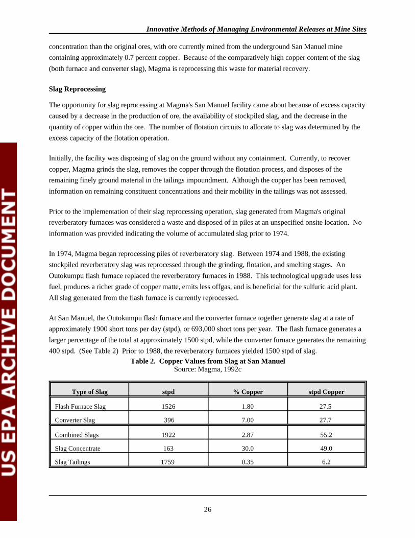
At San Manuel, the Outokumpu flash furnace and the converter furnace together generate slag at a rate ofapproximately 1900 short tons per day (stpd), or 693,000 short tons per year. The flash furnace generates alarger percentage of the total at approximately 1500 stpd, while the converter furnace generates the remaining400 stpd. (See Table 2) Prior to 1988, the reverberatory furnaces yielded 1500 stpd of slag.
Table 2. Copper Values from Slag at San ManuelSource: Magma, 1992c
Type of Slag stpd % Copper stpd Copper
Flash Furnace Slag 1526 1.80 27.5
Converter Slag 396 7.00 27.7
Combined Slags 1922 2.87 55.2
Slag Concentrate 163 30.0 49.0
Slag Tailings 1759 0.35 6.2
Innovative Methods of Managing Environmental Releases at Mine Sites
27
Based on information obtained from Magma's response to EPA's National Survey of Solid Waste fromMineral Processing Facilities, slag from the flash furnace contains the following constituents: copper(2.39%); iron (46.95%); total sulfur (0.77%); aluminum (1.70%); and silicon (14.71%). The survey did notinclude a list of concentrations of constituents in converter furnace slag, however, main constituents aresimilar with the copper content being higher (5 to 7%). Additional data on slag constituent concentration wasnot available (Magma, 1988).
Slag Cooling
Copper recovery from slag is dependent on the treatment of the material prior to beneficiation at the mill. Slow cooling in the initial stages is imperative to allow copper particles to coalesce and crystallize. According to facility personnel, the first eight hours of cooling are the most critical for optimum copperrecovery.
Molten slag from the flash smelter and converter furnaces is transferred to slag cooling pits to allow slag toharden and for copper minerals to crystallize. Slag from the flash furnace is transported in a 40 ton ladlecarrier (Kress slag pot carrier) to one of 168 flash furnace cooling pits, each approximately 26.5 feet long and14.5 feet wide. Each pit holds one ladle; slag from one ladle typically forms a layer 20 to 24 inches thick.
Slag from the converter furnaces is placed in one of 72 converter slag cooling pits which are smaller than theflash furnace pits: the converter slag pits have a capacity of only 26.6 tons and are each 26.5 feet long and 11feet wide.
Both the converter and the flash furnace slag pits are arranged in large blocks. Each block is separated byareas large enough to allow vehicle access. The cooling pits are constructed of crushed slag that createsberms around each pit. The pits are filled on a continuous cycle to optimize their usage so at any one timethere is likely to be pouring of molten slag, air cooling, water cooling, dozer ripping and preparing of pits forthe next cycle occurring.
After slag has been placed in the cooling pits, the slag is left to air cool for 8 hours. This is followed byvariable periods of water cooling and additional air cooling for a total of 2-3 days. A water spray system isused for the water cooling sequence. A main water line (6" to 8" diameter) delivers water to 18 spray nozzlesthat run down the center of each block of cooling pits. Water spray to individual blocks can be controlled sothat spray is kept off unused pits. A process flow diagram provided by Magma (Figure 6) lists the normalflow rate of water used in slag cooling as 1100 gallons per minute (gpm), with a design flow of 1500 gpm. The timing of water application is dependant on smelter demands; originally, 96 hours of cooling wasplanned, but due to the increased rate of slag generation, Magma decreased the total period of cooling.
When the slag has hardened, a dozer-ripper is used to break up the solidified slag. A front-end loader thenpicks up crushed slag and transfers it via trucks to a 50-ton hopper. The hopper is equipped with a 24-inchgrizzly, with a crushing plant underneath. Slag is reduced in size to minus 8-inch pieces by a 32 x 42-inchjaw crusher. The jaw crusher is dedicated to the slag processing system, although it is the same type as that
Innovative Methods of Managing Environmental Releases at Mine Sites
28
used for ore. Crushed slag is discharged from the jaw crusher to a 36-inch belt conveyor that passes to a 48-inch belt conveyor before discharging to the crushed slag stockpile, which has a 2000 ton capacity. Front endloaders remove crushed slag from the stockpile for transport to the concentrator crushing and grinding circuit(Magma, 1992c).
Until 1991, Magma operated a vibrating screen (5 x 16-foot single deck) for separation of fines less than 1/2-inch size. This separating equipment was a high maintenance item, with frequent breakdowns requiringfrequent repairs; therefore it was removed from the crushing system. Although the fines were initially reusedas building material for berms between individual cooling pits, they are no longer segregated and all material,including material less than 1/2-inch is subjected to flotation.
Flotation
San Manuel operates two separate, two-stage froth flotation systems, one for ore and another for slag. Of theeight flotation circuits at San Manuel, one is dedicated to slag flotation. The ore and slag flotation circuits areexactly the same except that a different primary collector, Dithiophosphate 55741, is used in slag flotation. Methylisobutyl carbonol (MIBC) is used as a frother in both flotation circuits. Collectors in the ore circuitinclude sodium xanthate, fuel oil (jet fuel A, which is used as a molybdenum collector), and VS M8, aproprietary flotation agent containing carbon disulfide. The underflow from both the slag and ore flotationcircuits is sent to the tailings thickener and onto the tailings impoundment.
The eight flotation circuits include a total of ten 2,000 cubic foot rougher cells, and 143 rougher cells ofsmaller dimensions (300 cubic feet). Cleaner flotation takes place in sixteen 39-foot high column flotationcells that concentrate the slag/ore to 30 percent copper. The overflow from rougher flotation is transferred toa cleaner/column flotation stage in each circuit, while underflow goes to Magma's tailings thickeners (Figure7). In each circuit, the second stage of flotation occurs in the 39-foot high, 40 cubic feet cleaner/column cells. In seven of the eight circuits (ore circuits), the overflow from the ore cleaner cells goes to separate collectionlaunders for transport to the molybdenite plant. (The underflow goes to the ball mills and is returned to therougher for additional flotation.) Slag concentrate, produced in one of the eight flotation circuits, goesdirectly to dryers and is not sent through the molybdenite plant. Slag concentrate has a copper concentrationof approximately 30 percent; identification and concentrations of other constituents was not obtained.
Slag concentrate fed to the furnace composes approximately 7 percent of the total furnace feed. The exactamount of slag concentrate feed ranges from 3 to 10 percent and is adjusted as necessary for the proper feedcomposition. Variables affecting the furnace feed rate include the amount of sulfur, iron, and silica in the slagconcentrate. Details on how furnace feed is controlled were not discussed.
According to facility personnel, the slag reprocessing system now operates at a slag feed rate of 110-120tons/hour, but Magma will soon process 130 tons of slag per hour. Because of the increase in slaggeneration, Magma plans to expand the number of slag cooling pits.
Innovative Methods of Managing Environmental Releases at Mine Sites
29
Slag reprocessing generates slag tailings which are combined with the ore tailings. According to Magma,primary constituents in slag tailings are silica, iron, magnesium, sodium, and smaller amounts of copper, lead,and zinc, as well as other trace elements. Specific data on the constituents were not discussed.
The amount of slag tailings as a percentage of total tailings disposal at San Manuel is approximately 3 to 6percent. According to Magma, 65,000 short tons of slag tailings were generated and disposed in 1990, and69,200 short tons in 1991. The total quantity of tailings generated (slag and ore combined) in 1990 was17,000,000 short tons and 17,689,000 short tons in 1991.
Tailings from the mill are typically 30 percent solids and after the thickeners, are sent to the tailingsimpoundments as 50 percent solids slurry. Slag tailings are co-disposed with ore tailings into tailingsimpoundments, located approximately 1/2 mile west of the San Pedro River. According to Magma, SanManuel's water reclaim system reclaims most tailings water, leaving only 12.5 percent moisture content in thetailings. The tailings liquid has a pH of 8.4.
Because all slag is reprocessed, there is no permanent disposal of slag at the Magma site. Slag pits are usedto allow cooling of the slag prior to crushing, flotation, and re-smelting. According to facility personnel mostof the cooling water evaporates. Any remaining water runs off the cooling pits through unlined washes orshallow culverts to the tailings ponds. During the site visit white evaporite residue was observed in and alongthe drainage.
Costs
According to facility personnel, since the slag reprocessing operations involve the use of existing equipment,no purchase of new equipment/materials, installation/site preparation, or engineering and procurement costswere necessary for application of the process to begin. No specific cost information on the construction ofthe cooling pits or equipment was obtained.
Detailed breakdown of costs were not provided by Magma, but facility personnel indicated a general cost of$5/ton of slag processed through the mill circuit. No information was provided on energy or labor costs. Water costs were reported by Magma to be minimal; the facility reuses water from its tailings ponds for usein cooling water, dust suppression, plant make-up water, etc.
Magma stated that there were no cost savings that it was aware of, such as reduced disposal fees, decrease inraw materials, etc. During the site visit, however, facility representatives pointed out that the reprocessing ofslag reduced the volume of ore that needs to be mined, thus resulting in an unspecified savings in miningcosts. By reducing the volume of ore required for full mill operation, the facility is also extending the life ofmine based on the existing volume of minable ore. According to facility personnel, approximately one ton ofslag displaces two tons of ore; however, resolution of this ratio is unclear as slag has a copper concentrationof 2.8% while the ore has approximately 0.7% copper.
Benefits

Innovative Methods of Managing Environmental Releases at Mine Sites
30
The key benefit derived from San Manuel's slag reprocessing operation has been the economic recovery ofadditional copper. Not only has the slag reprocessing operation provided a source of copper, but it has beenprovided by what is normally a waste material. It is important to note however, that while the facility haseliminated one waste stream (slag), there is an increase in tailings disposal.
Currently, to recover copper, Magma grinds the slag, removes the copper and disposes of the remaining finelyground material in the tailings impoundment. Although the copper has been removed, no data were availableon the remaining constituents in the tailings and their mobility.
According to the Magma representatives, since all revenues (from processing of slag into concentrate) areaccounted for as internal toll costs between the smelting and milling units, it is impossible at this time todetermine a set value on revenues generated or saved due to the reprocessing of slag.
Limitations
The success of copper recovery from slag reprocessing operations at San Manuel is due in large part to theavailability of an existing, fully integrated facility with both a mill and a smelter. At other locations, withoutsuch a set-up, the operation would be much more difficult to establish and potentially cost prohibitive. Asubstantial capital investment would be required if the equipment were not already on-site; Magma's capitalcosts related to reprocessing were low.
Obviously, the percent copper in slag, or other waste material, is a significant factor in determining itssuitability for reprocessing. As for the minimum content of copper that could feasibly be recovered, Magmaindicated that there were too many variables, including distance from slag source to mill and smelter, rate ofcooling, type of furnace, and economic factors such as the selling price of copper, etc. to identify a specificconcentration.
The rate of slag cooling and subsequent crystal growth was identified as a major technical factor determiningthe success of slag reprocessing. Because the cooling rate of the slag is crucial to the successful recovery ofcopper, not all slag is suitable for slag reprocessing. This is especially so when considering reprocessing ofexisting stockpiles of slag as opposed to reprocessing of currently generated slag.
Other limitations that may be encountered include rising energy and maintenance costs. Other sites may haveadditional technical limitations, for example, reprocessing with reverberatory slag is not as favorable as withflash furnace slag: reverberatory slag is harder to grind and to crush.
Conclusions
The opportunity for slag reprocessing at Magma's San Manuel facility came about because of excess capacitycaused by a decrease in the production of ore, the availability of stockpiled slag, and the decrease in thequantity of copper within the ore. The number of flotation circuits to allocate to slag was determined by theexcess capacity in the process. Based on available information presented by Magma, with the general cost of

Innovative Methods of Managing Environmental Releases at Mine Sites
31
$5/ton of slag quoted by Magma and a derived copper value (from the slag) of approximately $0.082/pound,slag reprocessing appears to be a profitable operation.
According to the 1990 Report to Congress on Special Waste from Mineral Processing, two other facilities,in addition to San Manuel, utilize the concentrator to recover copper values from smelter slag: Copper Rangein Michigan and the Kennecott Mine in Utah. Unlike the Utah facility that operates a separate slag flotationoperation, San Manuel and Copper Range each use similar operations for slag and ore which result in co-generation of slag tailings (another special waste) and ore tailings from the operation.
Contacts
Magma Copper CompanyEldon HelmerDirector of Environmental Affairs(602) 575-5644
ArizonaRoger W. KennettEnvironmental Program SupervisorWater Permit UnitArizona Department of Environmental Quality(602) 207 - 4607
Bureau of MinesJanice JollyCopper Commodities Specialist(202) 501-9414
David ForsheyAssociate Director for Metallurgy Research(202) 501-9291
Phillipe MeikleMining Technology, Health & Safety(202) 501-9321
References
Arizona Department of Mines and Mineral Resources. 1990. The Primary Copper Industry of Arizona in1989, Special Report No. 16, by Richard R. Beard, October, 1990.
EPA, 1990. Report to Congress on Special Wastes from Mineral Processing; Summary and Findings,Methods and Analyses, Appendices. EPA/530-SW-90-070C, July 1990.
Magma, 1992. Correspondence from Alfred Celaya, Senior Environmental Engineer, Magma CopperCompany to Robert Tonetti, Special Waste Branch, U.S. Environmental Protection Agency, October21, 1992.
Magma, 1992b. Description of Mining and SX/EW Operations. Undated.
Innovative Methods of Managing Environmental Releases at Mine Sites
32
Magma, 1992c. Slag Reprocessing Operations: Acid Plant Operations. Undated.
Magma, 1988. National Survey of Solid Wastes from Mineral Processing Facilities, EPA questionnaire, asresponded to by Magma Copper Company, San Manuel Division. June 1989.
Magma, 1988a. Pamphlets re: Operations at San Manuel, including "The Underground Mine"; "TheSmelter"; "Concentrating at San Manuel"; "The Open Pit Oxide Mine"; "In situ Leaching"; "SolventExtraction/Electrowinning"; "Electrolytic Refining"; and "Continuous Cast Copper Rod". 1988.
Weiss, 1985. Society of Mining Engineers, Mineral Processing Handbook, Volumes 1 and 2; by SME of theAmerican Institute of Mining, Metallurgical, and Petroleum Engineers, Inc., Norman L. Weiss,Editor-in-Chief; 1985.
Volume I, Section 5: Flotation, N. Arbiter, Section Ed., H. Cooper, M.C. Fuerstenau, C.C. Harris,M.C. Kuhn, J. D. Miller, and R.F. Yap, Associate Eds., pp. 5-1 to 5-110.
Volume II, Section 14H: Copper - Processing of Concentrates and Development Trends,D.C.Moore, pp. 14H-3 to 14H-14.
Wiley and Sons, Encyclopedia of Chemical Technology, Third Edition, Volume 9, Extractive Metallurgy, pp.749-750, Kirk-Othemer, 1980.

Innovative Methods of Managing Environmental Releases at Mine Sites
33
EPA Response to Comments
Magma Copper Company submitted written comments on this report to EPA in a letter dated July 6, 1993. Magma requested that minor editorial changes be made to correct factual information regarding theiroperations. EPA corrected the draft to incorporate all of Magma's recommended changes.
The U.S. Bureau of Mines submitted comments on the report. These have been responded to as appropriate.
Innovative Methods of Managing Environmental Releases at Mine Sites
34
3.2 TAILINGS REPROCESSING OPERATION
Magma Copper Company's Pinto Valley Division (Pinto Valley) consists of two operations. The MiamiUnit, located adjacent to the town of Miami, in Gila County, Arizona, is a tailings reprocessing operation, thefocus of this section of the report, and an in situ leaching operation. Pinto Valley's second operation, thePinto Valley Unit, consists of an open pit mine and associated facilities located five miles west of Miami. The reprocessing operation started in 1989 and is proposed to continue through 1997. The reprocessingoperation, including the in situ leaching operation, employs 70 people. The site is located approximately 60miles east of Phoenix, Arizona (Figure 8). The area is characteristic of the semi-arid southwest region. Thetailings reprocessing operation involves reprocessing the Miami #2 tailings pile, which covers 210 acres andcontains 38 million tons of tailings. The pile was deposited between 1911 and 1932 (McWaters, 1991).
Pinto Valley hydraulically mines the tailings pile, leaches the tailings and produces copper by using a solventextraction/electrowinning facility. After leaching and washing of the slurried tailings, the remaining slurry ispiped overland approximately five miles to the Copper Cities Deep Pit for final disposal.
Miami #2 Tailings Pile
The Miami #2 tailings pile was deposited during the operation of a Miami Copper Company mine and mill. The operation used a gravity mill and later flotation to separate copper from the ore. The tailings weredeposited in six canyons adjacent to the mill using launders and spigot valves. Eventually, five canyons filledand one tailings pile was formed; it is now referred to as the #2 tailings pile.
The efficiency of the gravity separation method at the time is reflected in the copper content of the tailingsthrough the depth of the pile. The oldest tailings contain 0.72 percent copper while those deposited mostrecently contain 0.11 percent copper; the average copper content is 0.33 percent. Typically, the oldestdeposits are at the lowest portions of the #2 tailings pile. Approximately 55 percent of the copper is in anoxide form with the remainder being in the form of sulfides.
Because the top lifts of tailing deposition have very low copper contents (due to increased efficiency ofcopper concentration), Magma pre-strips the top layer in order to get to an economically recoverable zone. In general, the copper content increases with depth (and age) in the tailings pile. Magma still reprocesses thispre-stripped layer, although the copper recovered is extremely low.
Hydraulic Mining
The hydraulic mining system simplifies the remining operation in three ways. First, the hydraulic systemeliminates the need for excavating and hauling equipment normally associated with conventional mining. Second, the energy produced by the water jets serves to break down clay aggregates allowing more efficientseparation, and finally, the hydraulic action and acidic solution
Innovative Methods of Managing Environmental Releases at Mine Sites
35
provide the appropriate slurry necessary for the subsequent hydrometallurgical beneficiation.
Two sets of two, four-inch monitors (water canons) apply solution (raffinate), with a pH of 1.8, to theupstream face of the tailings pile at a pressure of 300 to 350 psi at a rate of 2,400 gpm. Originally, thesystem was designed to operate at a pressure of 435 psi, but Magma has reduced the operating pressure.
The monitors wash tailings down the face of the pile into a sump. Eductors, a type of vacuum pump that canpump air and water, generate a slurry that contains approximately 32 percent solids by weight. The twoeductors pump the slurry at a rate of approximately 500 tons per hour (McWaters, 1991).
The monitors, sumps and eductors advance as the face of the tailings pile recedes. The equipment isadvanced frequently so that the slurry paths are kept short, which in turn, prevents the solution frommigrating through the pile and into the groundwater (Hartman, 1992). The eductors move the slurry from thesumps to a grizzly. The grizzly is equipped with a screen that rejects material such as scraps of wood andother debris in the tailings, larger than 1/2 inch. The undersized material passes through the grizzly into atank where it is pumped to the processing plant.
Magma conducts periodic blasting of the tailings face to prevent large, unstable blocks from sloughing. Theblasting is done for safety reasons and to protect the monitor stations from being buried.
Leaching
The low pH of the solution used in the monitors actually begins the leaching as the slurry is washed off theface of the tailings pile. The first step within the plant is the leach tank (dimension of 20' x 30'), where thepH of the slurry is lowered to 1.5 using sulfuric acid. The initial plan of the operation called for 14.5 lb ofsulfuric acid and 0.04 lb of flocculent per ton of tailing. The maximum capacity was proposed to be 12,000tons per day. Figure 9 shows the leach tank and thickeners in a process flow diagram. From the leach tank,the slurry goes to the first of two thickeners. The overflow from this thickener becomes the pregnant leachatesolution (PLS), which goes into a vessel where it is flocculated and clarified at a rate of 3,000 gpm. Thissolution is then sent to a pregnant leach solution pond and on to the solvent extraction circuit. The underflowfrom the first thickener is pumped to a second vessel, washed with raffinate, and pumped to the secondthickener. The overflow from the second thickener is ultimately returned to the mining circuit as feed for themonitors. The underflow is pumped into a vessel, washed with raffinate, and then pumped into the tailingsdisposal area (McWaters, 1991). The first and second thickeners are 375 feet and 180 feet in diameter,respectively. Through a single control room, a computer is used to monitor and control most of the operations throughoutthe facility. A printout of the computer screen showing instantaneously adjusted flow rates is presented inFigure 10. Explanation of volumes and rates depicted in the Figure were not obtained.

Innovative Methods of Managing Environmental Releases at Mine Sites
36
Solvent Extraction
The pregnant solution pond (HDPE-lined) is fed by both the overflow from the first thickener and thepregnant solution from the in situ operation (McWaters, 1991). The 6,000 gpm combined flow is fed intofour "trains" of solvent extraction. Within the solvent extraction tanks, over 90 percent of the copper istransferred into the organic phase. The organic phase solution consists of a 7 percent (by volume) liquid ionexchange agent (LIX 984) in kerosene. ®
After loading, the organic phase is pumped through two trains of mixer/settler vessels in series that cause thecopper to transfer to an electrolyte. The barren organic is then returned to the extractor vessels. Magma usesthe same SX/EW operation for reprocessed tailings and its in situ leach operation. There is no differencebetween the SX/EW operation for the reprocessed tailings solution and other SX/EW plants in use at othercopper sites.
Electrowinning
The amount of copper in the pregnant solution is concentrated approximately fifty fold in the process of beingtransferred to the electrolyte. Prior to electrowinning, the electrolyte is subject to flotation to remove anyentrained organic; additional information on the type of flotation was not available. The electrolyte solutionis then heated using steam and the internal heat of electrolysis. Prior to passing into the electrowinning tanks,particulates are removed from the electrolyte as it is passed through a bedded filter. In electrowinning cells,the copper in the electrolyte is readily electrowon onto stainless steel cathodes. The copper cathodesproduced are normally shipped to Magma's San Manuel facility for manufacture of copper rod.
Wastes
It is assumed that tailing reprocessing will continue as long as copper prices warrant. Ultimate disposal ofthe reprocessed mine tailings is in the Copper Cities Deep Pit. The Copper Cities Deep Pit is an abandoned,open copper pit approximately 700-feet deep. The bottom of the pit is at 3250-feet mean sea level (Figure11). The pit will ultimately be filled to the 3760' level. According to Magma and its consultants, Dames andMoore, this disposal was made possible due to the hydrogeologically isolated location of the deep pit.
Waste generated from the tailings reprocessing system consists of the underflow from the second thickener. Four centrifugal pumps direct the underflow from the second thickener through a 4.7 mile long pipeline to theCopper Cities Deep Pit. Magma worked with the U.S. Bureau of Land Management and InspirationConsolidated Copper Company to procure right-of-way easements.The tailings slurry consists of 50 percent solids, and is pumped at a rate of 2,710 gpm and has a pH of 2 to2.2. The 13-inch diameter, high density polyethylene (HDPE) pipeline is placed in unlined containmentditches, and operates at a maximum pressure of 360 psi.
After the tailings slurry is discharged, solids settle out in the Copper Cities Deep Pit. Barge pumps located inthe Copper Cities Deep Pit pump liquid from the surface back to the facility through 12 and 14 inch HDPEpipelines that parallel the slurry pipeline. The liquid returning from the pit is added back into the system at
Innovative Methods of Managing Environmental Releases at Mine Sites
37
the mining supply stage, i.e., the monitors. The pipelines' pressures and flows are monitored to identify andlimit leaks within the system (McWaters, 1991).
According to Dames and Moore (1987), because of the geology and faulted conditions that isolate the area ofthe Copper Cities Deep Pit from surrounding rock masses, and the relatively high aquifer level; water or otherliquids placed in the pit will not flow/commingle or contaminate the underlying and surrounding aquifers. EPA did not obtain additional information; technical review of the hydrogeologic reports was not conducted.
Prior to initiating tailings reclamation at the #2 tailings pile, Magma was required to prepare a GroundwaterProtection Plan in order to obtain the necessary permit from the State of Arizona. The permit states how fullthe Deep Pit may be filled. There are five groundwater monitoring wells that are sampled quarterly at theCopper Cities Deep Pit; data were not available for this review.
Costs
In 1981, a site-specific study showed that 57 percent total copper recovery could be economical, but thatadditional recovery would not be economically justified (McWaters, 1991). Magma started the operation inJuly 1989. Details were not made available because of confidential financial business information concerns.
In order to reprocess the Miami #2 tailings, Magma had to expand its existing SX/EW plant and refurbishtwo thickeners. Capital expansions involved increasing the number of electrowinning tankhouse cells from60 to 104. The plant was estimated to cost $19.6 million in 1988 (McWaters, 1991). In order to run theplant continuously, handling 12,000 stpd of tailings, Magma needed to hire 23 additional people. Additionalcost information was not provided.
Operating costs are 50 to 55 cents per pound of copper; with depreciation, the cost is 84 cents per pound. According to facility personnel, this is one of the highest operating costs of any Magma operation. The costof power is $100,000 per month. Initially, the electrical energy consumption per pound of cathode copperwas calculated by Magma to be 3.0 kwh. Additional operating cost information was not obtained.
According to facility personnel, the Pinto Valley operation is essentially a closed loop system for water usage. Because there is a high evaporation rate in the area, 66+ inches annually, there is speculation by some Magmarepresentatives that towards the end of the life of the reprocessing operation there may be a problem withexcessive evaporative loss from the surface of the Copper Cities Deep Pit.
Benefits
The environmental benefit derived from the operation results from the removal of the tailings pile located in adrainage adjacent to the town of Miami and redepositing the tailings in an abandoned open pit in a relativelyremote location. Information confirming whether this removal and redeposit will provide a net environmentalbenefit was not obtained. According to facility personnel, recently, the operation has been economicallyprofitable due to the recovery of copper and is expected to continue to be profitable in the future.
Innovative Methods of Managing Environmental Releases at Mine Sites
38
Limitations
Limitations to Technology Transfer
Magma credits two reasons for success of tailings reprocessing at this facility: (1) the high concentration andamount of copper that is present in the tailings, and (2) the tailings have had a long time to oxidize, thusmaking the copper more readily available. Other sites may have a lower percentage of copper in the tailings,which may make reprocessing less economical. Newer deposits may also be less economical.
Additional copper recovery may be possible by extra oxidation, flotation or elevated temperature leachingcircuits, however, at Pinto Valley, they were not determined to be economically attractive.
Site-Specific Technical Issues
Some of the problems encountered at Magma's Pinto Valley tailings reprocessing operation have beenmoving the hydromonitors around. Placement of the monitors involves careful planning in choosing a sitewhere there is an even mix of slimes and coarse grain material. The high pressure hoses experience frequentleaks and require constant attention.
A critical factor is the amount of time the slurried solution is in the tanks. The consistency of the slurry isanother important operating parameter and is described as the slime vs. coarse content of the slurry. Forexample, if there is not enough slimes, the slurry sticks and does not flow smoothly through the system. Ifthere is not a good mix of slimes and coarse grain then it is difficult to control the thickeners. In order tocontrol the grain mixture, Magma tries to keep two of the four monitors in the slimes and two in a sandy area.
Magma reports that initially, there were start-up problems associated with the electrowinning circuit, and withthe refurbished thickeners (details not provided). Earlier attempts to mine and then slurry the tailings byconventional methods proved unsuccessful in part because of clay balling. The use of a hydraulic monitoringsystem avoids clay balling by breaking down the strong clay bonds between particles through use of the highenergy, high pressure monitor stream.
There have been occasional releases and spills from the slurry pipeline system and Magma has responded asnecessary to such releases.
Conclusions
Since 1989, Magma has recovered copper from a waste source, its Miami #2 tailings pile at Pinto Valley. Recently, the operation has been economically profitable. By reprocessing the tailings, Magma is removing alarge volume of waste that sits adjacent to the Bloody Tanks Wash, which is perched on the edge of the townof Miami.
Innovative Methods of Managing Environmental Releases at Mine Sites
39
According to Magma facility personnel, the Copper Cities Deep Pit, where the reprocessed waste will bedisposed of, is a hydrogeologically isolated unit and that waste will not be in contact with the surroundingaquifers. However, sufficient information to provide an independent evaluation of the environmental impactof the final deposition of waste tailings is not available.
Contacts
Magma Copper CompanyEldon HelmerDirector of Environmental Affairs(602) 575-5600
ArizonaRoger W. KennettEnvironmental Program SupervisorWater Permit UnitArizona Department of Environmental Quality(602) 207-4697
References
Arizona Department of Environmental Quality. 1991. Incident Report, March 15, 1991.
Arizona Department of Environmental Quality. 1989. Inter-Office Memorandum from B.K. Thatcher Jr. toT. Levandowsky dated July 20, 1989.
Arizona Department of Mines and Mineral Resources. 1990. The Primary Copper Industry of Arizona in1989, Special Report No. 16, by Richard R. Beard, October, 1990.
Dames and Moore. 1987. Hydrogeologic Evaluation: Disposal of Tailings in Copper Cities Deep Pit, forPinto Valley Copper Corporation.
Hartman, Howard L. 1992. SME Mining Engineering Handbook, 1992. Society for Mining Metallurgy andExploration Inc.
Magma Copper Company, Informational brochure. Undated.
Magma Copper Company, Pinto Valley Division. 1991. Spill Reports submitted to Arizona Department ofEnvironmental Quality, June 1989 to March 1991.
Magma Copper Company, Pinto Valley Division. 1987. Conceptual Notice of Disposal, Miami TailingsMine Site. Submitted to Arizona Department of Environmental Quality.
Magma Copper Company, Pinto Valley Division. 1987. Groundwater Quality Protection PermitApplication, Miami Tailings Reprocessing Project.
McWaters, T. 1991. Developing Magma's Tailings Leach Operation. Prepared for presentation at theAIME Hydrometallurgical Meeting, Spring 1991, San Manuel, AZ.
Site Visit, 10-28-92. EPA Site Visit to Magma Copper Company, Pinto Valley - Miami Operation, Arizona,October 28, 1992.
Innovative Methods of Managing Environmental Releases at Mine Sites
40
Smith, H.C. 1991. Report of Abnormal Discharge Dated September 5, 1991. Letter to Wayne Hood(ADEQ) from Harry Smith (Magma).
Smith, H.C. 1991. Response to 308-FY92-37 Letter Requesting Information, Letter to Harry Seraydarian(EPA) from Harry Smith (Magma).
Southwestern Pay Dirt. 1992. "Produced 9 Million Pounds of Copper Last Year: Unique HydraulicOperation is Recovering Assets, Removing an Old Dump", October, 1992.
U.S. Environmental Protection Agency. 1992. Findings of Violation and Order, Docket No. IX-FY92-08,issued to Magma Copper Company.

Innovative Methods of Managing Environmental Releases at Mine Sites
41
EPA Response to Comments
Magma Copper Company submitted written comments on this report to EPA in a letter dated July, 15, 1993. Magma requested that minor editorial changes be made to correct factual information regarding theiroperations. EPA corrected the draft to incorporate all of Magma's recommended changes.
The U.S. Bureau of Mines submitted comments. These have been addressed as appropriate.
Innovative Methods of Managing Environmental Releases at Mine Sites
42
3.3 PIPE RECYCLING/REUSE
IMC operates eight phosphate rock mines and plants that cover an area of 115,854 acres in Polk,Hillsborough, and Manatee counties in West Central Florida (this includes leased and owned land underIMC's control, of which only portions are actively mined at any one time). Phosphate rock is the raw materialused for the manufacture of phosphate fertilizer, animal feed supplements, and industrial chemicals includingphosphoric acid, trisodium phosphate, and sodium tripolyphosphate. IMC's Florida operations have acapacity of 23 million tons per year, which is 13 percent of world capacity and 35 percent of U.S. capacity.
The climate, availability of water, topography, and physical characteristics of the deposit make the use oflarge dragline excavators and hydraulic pumping systems the most economical mining method to mine thephosphate zone, which consists of a mixture of phosphate, sand, and clay, normally containing 20 to 25percent moisture (collectively known as "matrix"). IMC operates up to 18 draglines (14 at the time of the sitevisit). The draglines have a reach of up to several hundred feet and buckets with capacities up to 65 cubicyards. A dragline excavates a 200 to 400 foot wide semicircular area before moving and mining the area itevacuates. The ore or matrix, which is typically 5 to 20 feet thick, lies under 20 to 40 feet of overburden. The dragline first strips the overburden, placing it into adjacent mined areas for later use in reclamation. Alternatively, when mining at the perimeter of an area that will later be used as a clay settling pond (whosecells are typically about one mile square), overburden may be used to construct the raised dams that surroundthe pond.
Once the overburden is removed from over the matrix, the dragline excavates the matrix itself. With eachbucketful, the dragline pivots and dumps the matrix from the bucket into a "well." The well is simply anexcavation about 50 feet in diameter and 10 to 15 feet deep. In the well, two hydraulic monitors blast thematrix with 10,000 to 15,000 gpm of water at 150-250 psi, which further breaks up the matrix and forms aslurry. Water from the monitors is pumped through steel pipelines from clay ponds near the beneficiationplants.
After being blasted by the monitors, the matrix slurry passes through an 8-inch grizzly to screen out oversizematerials, which are further broken up by the monitors. A pit pump lifts the slurry, which has 30-40 percentsolids, from the well into a steel pipeline at a rate of 1,800-2,000 gpm for transport to the beneficiation plant. Because the areas being mined and the beneficiation plants are some distance apart--from one to over sixmiles as of mid-1992--a number of intermediate "lift pumps" are necessary to keep the matrix movingthrough the pipelines at about 19 feet per second. The first lift pump is generally within 1,500 feet of thewell and additional lift pumps are placed every 2,900 to 4,000 feet along the pipeline's length. Because thedragline moves, the well, pit pump, and the first section of the pipeline (i.e., the section between the well andthe first lift pump) are moved every three to four days to allow the well to remain in the dragline's boomreach.
Once it reaches the beneficiation plant, the matrix is separated into clays, fine product, pebble product, andoversized debris. The two major wastes, tailings (which are fine, well-sorted rounded sands) and clay are
Innovative Methods of Managing Environmental Releases at Mine Sites
43
transported to their respective disposal sites. The tailings are transported by pipeline to areas that will bereclaimed after mining is completed, and then used to backfill the mined areas; they also may be transportedand stored in piles prior to being used for such purposes as dam construction. The clays--again as a slurry--are transported by pipeline to the onsite clay disposal impoundment. As can be seen, pipelines are used fornearly all materials that are transported on and around IMC's operations.
Program Description
IMC's waste minimization program that was the focus of EPA's examination involves the reuse and recyclingof the steel pipe that is used to transport matrix slurry, water, tailings, clay, and other materials. At IMC'soperations in July 1992, there were approximately 194 miles of steel and polyethylene pipe in use and ininventory.
IMC obtains maximum use from steel pipe in a number of ways:
Pipe used for matrix and clay transport is periodically rotated to ensure that wear is evenly spacedover the full diameter of the pipe
To the extent possible, pipe no longer suitable for the most demanding use, in matrix pipelines, isthen used in other less demanding pipelines, such as tailings or hydraulic pipelines
Pipe no longer suitable for use in pipelines is either used for other purposes (e.g., culverts) or sold foroff-site reuse or as scrap.
Table 3 shows the amount of the various types of pipe on hand in July 1992. Information on how much ofthe total inventory consisted of steel pipe and how much was polyethylene was not available. Each year, IMCpurchases approximately 183,000 feet (35 miles) of 3/8-inch thick steel pipe in 50-foot sections. The pipehas a 75,000 psi tensile strength, 45,000 psi yield strength, and a Brinell hardness of 180 minimum. Pipewith varying diameters is purchased, with most pipe purchased in 1991 being 18-inch. The 18-inch size steelpipe is the most widely used, as can be seen in Table 4: in 1991, 110,000 feet or 60 percent of all pipepurchased was the 18-inch size, but the amounts and sizes needed reportedly varies from year to year. Table4 shows the various sizes and uses as of September 1992.

Innovative Methods of Managing Environmental Releases at Mine Sites
44
Type of pipe Purpose Length (feet)
Matrix Slurry from mines to plants 248,350
Hydraulic Water from clay ponds to mines 129,800
Tailings Slurry from plants to storage/ reclamation areas 190,625
Feed In-plant, from washers to float plant 41,900
Debris From old debris area to plant 8,750
Waterjack Transport mine water from pit to system or discharge 30,625
Overburden Slurry from deeper mines (below where dragline can reach) 19,200
Clays Transport clays from plant to clay ponds 70,600
Spare Stored for use in pipelines--some new, some used 233,775
Scrap Stored for other on-site uses or sale to scrap dealer 51,050
TOTAL 1,024,675
Table 3. IMC Inventory of Pipe In Use or Available, July 1992
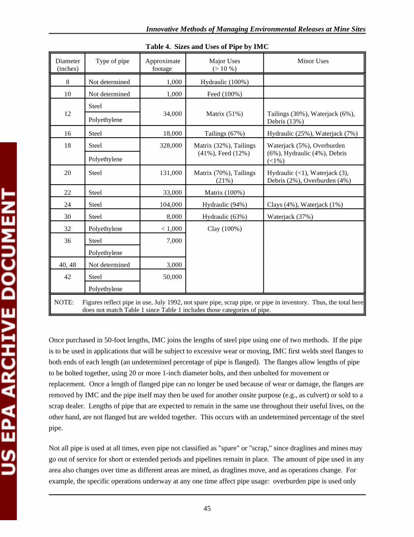
Innovative Methods of Managing Environmental Releases at Mine Sites
45
Diameter(inches)
Type of pipe Approximatefootage
Major Uses(> 10 %)
Minor Uses
8 Not determined 1,000 Hydraulic (100%)
10 Not determined 1,000 Feed (100%)
12Steel
34,000 Matrix (51%) Tailings (30%), Waterjack (6%),Debris (13%)Polyethylene
16 Steel 18,000 Tailings (67%) Hydraulic (25%), Waterjack (7%)
18 Steel 328,000 Matrix (32%), Tailings(41%), Feed (12%)
Waterjack (5%), Overburden(6%), Hydraulic (4%), Debris(<1%)Polyethylene
20 Steel 131,000 Matrix (70%), Tailings(21%)
Hydraulic (<1), Waterjack (3),Debris (2%), Overburden (4%)
22 Steel 33,000 Matrix (100%)
24 Steel 104,000 Hydraulic (94%) Clays (4%), Waterjack (1%)
30 Steel 8,000 Hydraulic (63%) Waterjack (37%)
32 Polyethylene < 1,000 Clay (100%)
36 Steel 7,000
Polyethylene
40, 48 Not determined 3,000
42 Steel 50,000
Polyethylene
NOTE: Figures reflect pipe in use, July 1992, not spare pipe, scrap pipe, or pipe in inventory. Thus, the total heredoes not match Table 1 since Table 1 includes those categories of pipe.
Table 4. Sizes and Uses of Pipe by IMC
Once purchased in 50-foot lengths, IMC joins the lengths of steel pipe using one of two methods. If the pipeis to be used in applications that will be subject to excessive wear or moving, IMC first welds steel flanges toboth ends of each length (an undetermined percentage of pipe is flanged). The flanges allow lengths of pipeto be bolted together, using 20 or more 1-inch diameter bolts, and then unbolted for movement orreplacement. Once a length of flanged pipe can no longer be used because of wear or damage, the flanges areremoved by IMC and the pipe itself may then be used for another onsite purpose (e.g., as culvert) or sold to ascrap dealer. Lengths of pipe that are expected to remain in the same use throughout their useful lives, on theother hand, are not flanged but are welded together. This occurs with an undetermined percentage of the steelpipe.
Not all pipe is used at all times, even pipe not classified as "spare" or "scrap," since draglines and mines maygo out of service for short or extended periods and pipelines remain in place. The amount of pipe used in anyarea also changes over time as different areas are mined, as draglines move, and as operations change. Forexample, the specific operations underway at any one time affect pipe usage: overburden pipe is used only
Innovative Methods of Managing Environmental Releases at Mine Sites
46
when mining deeper deposits that lie below a dragline's reach (and is used to move the overburden that liesbelow the dragline's reach), and debris pipe is used to mine material that was formerly disposed as debrisfrom one or a few areas.
As Table 4 indicates, IMC also uses various sizes of hard polyethylene plastic pipe. Although less expensivethan steel, the plastic pipe cannot take the pressures necessary for matrix transport due to its 150 psi burststrength. In addition, the plastic pipe is not as mobile and is more expensive to cut and reattach than steelpipe. It also is much more responsive to changes in temperature, becoming too inflexible and brittle for someuses in cold weather and too flexible for some uses in the heat of summer. In cases where pipe is laid more orless permanently, and where the disadvantages are overcome by economics, however, plastic pipe has provedsatisfactory. Each of the major uses of pipe at IMC's central Florida operations is described below.
Matrix Pipe
Matrix slurry is pumped from the well adjacent to the mine to the beneficiation plant in steel pipelines at arate of 19 feet per second. The matrix, which is basically one-third phosphate, one-third sand, and one-thirdclay, is mixed with enough water to ensure movement over the long distances necessary (up to eight miles) tothe beneficiation plant. Because of the morphology of the matrix components coupled with the line pressure,there is considerable scouring and wear on the inside of the pipe. Scouring is most severe on the bottomquadrant of the pipe and over a period of months can simply wear through the entire thickness of the pipe. Ifnot prevented or avoided, pipe failure interrupts the flow of matrix to the plant and necessitates unscheduledand costly shutdowns. To obtain the maximum length of service possible for matrix pipe while minimizingpipe failure, IMC has developed a matrix pipe management program, which involves the periodic rotation ofmatrix pipe.
IMC's matrix pipelines ranged from slightly over one mile to 6.2 miles in length in September 1992, and canreach eight miles or more depending on the area being mined. The pipelines are made of steel pipe 12, 18,20, or 22 inches in diameter, as shown in Table 5. The size is based on the rate at which matrix is pumpedfrom the mine(s) to the plant, which in turn is a function of the capacity of the specific dragline serving themine (in some cases, matrix from two draglines enters the same pipeline). Each 50-foot length of matrix pipeis flanged on both ends; the flange on each end of each 50-foot length of pipe is joined to the flange on thenext length by 20 or more bolts that are 1 to 1.5 inches in diameter.
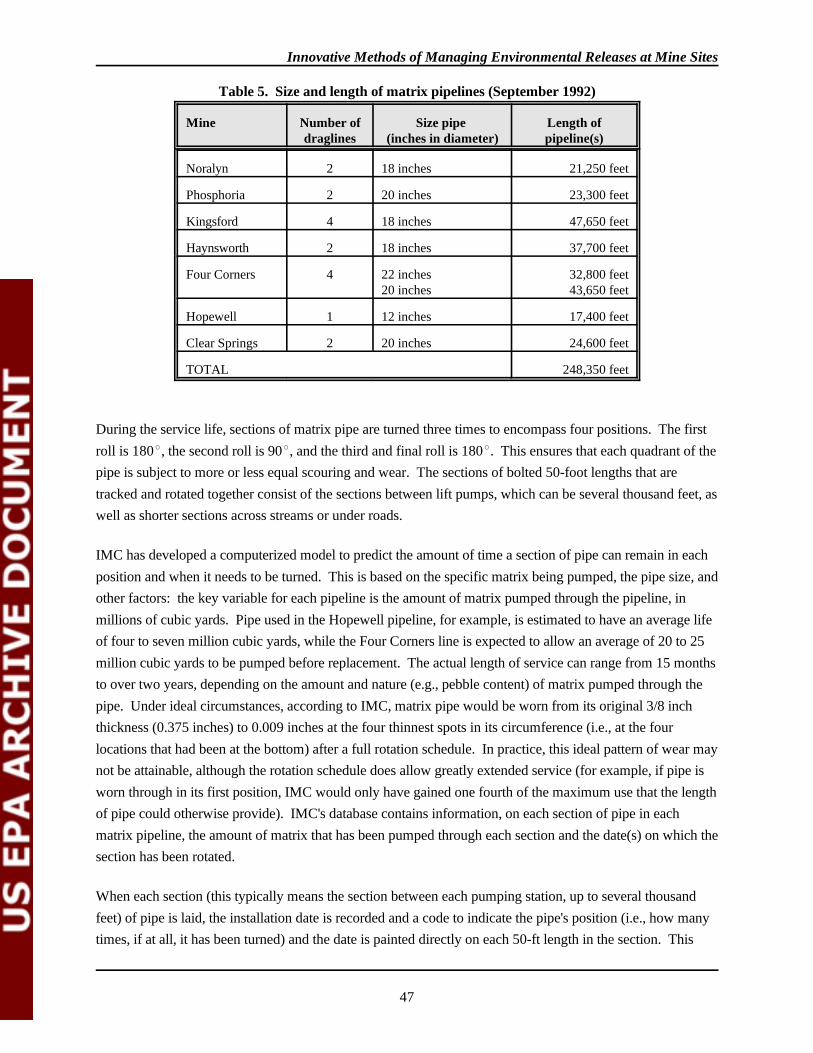
Innovative Methods of Managing Environmental Releases at Mine Sites
47
Mine Number ofdraglines
Size pipe (inches in diameter)
Length ofpipeline(s)
Noralyn 2 18 inches 21,250 feet
Phosphoria 2 20 inches 23,300 feet
Kingsford 4 18 inches 47,650 feet
Haynsworth 2 18 inches 37,700 feet
Four Corners 4 22 inches20 inches
32,800 feet43,650 feet
Hopewell 1 12 inches 17,400 feet
Clear Springs 2 20 inches 24,600 feet
TOTAL 248,350 feet
Table 5. Size and length of matrix pipelines (September 1992)
During the service life, sections of matrix pipe are turned three times to encompass four positions. The firstroll is 180 , the second roll is 90 , and the third and final roll is 180 . This ensures that each quadrant of thepipe is subject to more or less equal scouring and wear. The sections of bolted 50-foot lengths that aretracked and rotated together consist of the sections between lift pumps, which can be several thousand feet, aswell as shorter sections across streams or under roads.
IMC has developed a computerized model to predict the amount of time a section of pipe can remain in eachposition and when it needs to be turned. This is based on the specific matrix being pumped, the pipe size, andother factors: the key variable for each pipeline is the amount of matrix pumped through the pipeline, inmillions of cubic yards. Pipe used in the Hopewell pipeline, for example, is estimated to have an average lifeof four to seven million cubic yards, while the Four Corners line is expected to allow an average of 20 to 25million cubic yards to be pumped before replacement. The actual length of service can range from 15 monthsto over two years, depending on the amount and nature (e.g., pebble content) of matrix pumped through thepipe. Under ideal circumstances, according to IMC, matrix pipe would be worn from its original 3/8 inchthickness (0.375 inches) to 0.009 inches at the four thinnest spots in its circumference (i.e., at the fourlocations that had been at the bottom) after a full rotation schedule. In practice, this ideal pattern of wear maynot be attainable, although the rotation schedule does allow greatly extended service (for example, if pipe isworn through in its first position, IMC would only have gained one fourth of the maximum use that the lengthof pipe could otherwise provide). IMC's database contains information, on each section of pipe in eachmatrix pipeline, the amount of matrix that has been pumped through each section and the date(s) on which thesection has been rotated.
When each section (this typically means the section between each pumping station, up to several thousandfeet) of pipe is laid, the installation date is recorded and a code to indicate the pipe's position (i.e., how manytimes, if at all, it has been turned) and the date is painted directly on each 50-ft length in the section. This
Innovative Methods of Managing Environmental Releases at Mine Sites
48
information is then entered into IMC's computer program. Each month, IMC issues a monthly yardagestatement that inventories the pipe at each mine and indicates which sections of pipe are due to be rolled andwhen. This is based on the amount of matrix that has been pumped through the pipe, with about one-fourthof the "yardage life" allocated per quadrant.
When the turn date approaches, or when field measurements or judgment indicate that pipe should be rotated,the line foreman awaits a routine shutdown (generally, the beneficiation plant shuts down for eight hoursevery three weeks for routine maintenance, and there also are other unscheduled shutdowns that may provideopportunities) so that the pipe section can be turned without disrupting operations. Because of the weight ofthe pipe, a specially modified piece of equipment is used. When the pipe has been rolled, a new code andposition marker are painted on each 50-foot length of pipe in the section and the information is recorded toensure an accurate inventory. While the rolling schedule is pre-established based on the model's predictions,unforeseen circumstances (e.g., ruptures, leaks) can require that a section of pipe be rolled sooner or laterthan planned or be replaced. Thus, an aggressive field program is critical to IMC's operations: line crewsinspect and measure the remaining thickness of pipe with a calibrated sonic sensor to assess the degree ofwear (the schedule of inspection/measurement was not determined) and the results of these measurementsoften requires early rotation or replacement. When individual lengths of pipe within a section requirereplacement, the remaining lengths of pipe in the section are used in "mixed pipe" sections, as describedbelow.
Rolling a section of matrix pipe is not a trivial task. Each 50-foot length of pipe in a several thousand footsection must be unbolted from its neighboring length, turned 90 or 180 degrees depending on the schedule,realigned with connecting lengths, and rebolted. This all must occur within the relatively short scheduleddowntimes, which generally are about eight hours, and several sections may require rolling during these shortperiods. Thus, the entire exercise is carefully planned and executed by IMC.
In general, pipe nearest the dragline/well is subject to the most wear, with wear decreasing with distance fromthe mine (this is the result of coarser materials being broken up as they travel through the pipeline and thussubjecting the pipe to somewhat less wear). The first section of pipe in each matrix pipeline, the one runningbetween the well and the first lift pump, is not only subject to especially heavy scouring but also must bemoved periodically to accommodate the moving dragline and well. This frequent handling often damages 50-foot lengths of this section: besides the risks inherent in moving such pipe (new 18-inch pipe weighs about72 pounds per foot, or 3,600 pounds per 50-foot length), after such pipe has been rolled one or more times,portions of it are less than full thickness and is much more subject to bending or other damage when beinglifted and moved. Thus, individual 50-foot sections of pipe in the first section often require replacement. Because IMC rotates entire sections of pipe at one time, and because this can be accomplished only withequal-age sections (i.e., sections with equal-age 50-foot lengths), the first section of matrix pipelines isgenerally composed of what IMC calls "mixed pipe" (which generally consists of lengths of pipe fromsections that were previously broken up, as noted above). It was not determined how IMC establishes arotation schedule for "mixed pipe" sections, although it may be based entirely on line crew inspections.
Innovative Methods of Managing Environmental Releases at Mine Sites
49
(Because these sections are typically within the disturbed areas near the draglines, IMC noted that failures inthese sections could present more operational than environmental problems.)
After a section of matrix pipe is sufficiently worn in its fourth position, the pipe section is scheduled to bereplaced. When the operation is shut down, as noted above, the pipe is replaced with new pipe. All or someof the 50-foot lengths of the pipe may then be made available for use for other purposes, depending on thestructural integrity of the pipe. Pipe that is still fairly strong, for example, may be used for water or tailingstransport. Otherwise, it may be used for culverts or other on-site purposes or sold for reuse or recycling. Information on the amount and proportions of matrix pipe that are reused in other applications was notavailable, although IMC did indicate that "most" has some reuse potential.
Tailings Pipe
Since the tailings consist of a sand slurry, much less scouring of tailings pipe occurs since the sands are wellweathered and graded (rounded), which reduces the amount of scouring. Of the 190,625 feet of tailings pipe,an undetermined amount is polyethylene. Of the steel pipe, some has previously been used for matrixtransport (the percentage was not available). Previously used matrix pipe is used for tailings transport onlywithin the actual tailings disposal area, where failure of the pipe would not release tailings to undisturbedareas. After use for tailings transport, which can be for six years or more, if the pipe still has structuralintegrity, it may be used to transport water, or it can be sold as scrap, sold as piping, or used for culvertsonsite. No information was obtained on the amount of tailings pipe that is reused or recycled, on-site orotherwise.
Clay Pipe
Only large pipe is used for clay transport (nearly all is over 32 inches in diameter, as shown in Table 2). Some pipe lengths are flanged similarly to matrix pipe, and others are butt-welded into long sections;information on the amounts and proportions that are flanged was not available. Clays also scour the inside ofpipe a certain amount, but the wear is more evenly spread than in matrix pipe. As a result, flanged pipe usedto move clays is rotated twice, so that clay pipelines occupy three positions during their lives (except butt-welded pipelines, which remain in the same position and are not rotated). Apparently, the clay pipe rotationschedule is less well developed than the matrix schedule--at least, IMC did not provide information on therotation schedule. After pipe used for clay transport reaches the end of its useful life, which is generally afterthree to ten years of service, it is sold as scrap or for piping, or used as culverts, depending on the degree ofwear. No information was obtained on the amount of clay pipe that is reused or recycled, on-site orotherwise.
Water Pipe
A total of 129,800 feet of pipe is used to transport water from the clay ponds to the wells adjacent to eachdragline; as Table 2 indicated, many different sizes of pipe are used. IMC indicated that at least somehydraulic pipelines contained lengths of hard polyethylene pipe as well as steel pipe. These hydraulic lines,
Innovative Methods of Managing Environmental Releases at Mine Sites
50
as might be expected, experience relatively little wear. The end nearest the draglines do require moving as thewells move, so some pipe in these areas is occasionally damaged. Because it is the least demanding use,much of the steel pipe used in hydraulic pipelines has been used for other purposes previously; anundetermined amount of the 129,800 feet has been used for other purposes. Lengths of pipe in hydrauliclines are often welded together, although some sections, including those nearest the draglines, are flanged. Noinformation was obtained on the amount, if any, of hydraulic pipe that is reused or recycled, on-site orotherwise.
Other Pipe Uses
As shown in Table 3, pipe is used for a number of other purposes by IMC. These include in-plant feed pipefrom washers to flotation circuits, debris pipe, waterjack pipe, and overburden pipe. Although some portionsof these lines consist of previously used pipe, the precise amount was not determined. In addition, IMC hasover 233,000 feet of "spare" pipe in inventory, ready for use in pipelines. Some of this is new pipe, but muchhas been used for other purposes previously. Finally, IMC's mid-1992 inventory showed over 50,000 feet ofscrap pipe on hand, ready for off-site sale.
Flange Reuse/Recycling
IMC purchases new steel pipe and attaches recycled flanges through an assembly-line welding process. Pipethat is to be sold as scrap or as piping first has its flanges cut off. A service contractor picks up the flanges,removes the welded pipe section, cleans the flange, and returns the cleaned flange back to IMC for reuse onnew piping. Because the flanges are not subjected to scouring, they have a significantly longer service life.
Off-site Reuse and Recycling
Matrix pipe and other pipe that can no longer be used for materials transport (e.g., the pipe is worn out,thinned too much, bent, or broken) is sent to a staging area. At the staging area, any undamaged portions ofpipe are removed. These portions can then be either reused onsite as culvert or sold to a local scrap dealer asuseable pipe (reportedly for culverts, fence corner posts, gateposts, and low-volume water pumping). Damaged pipe is sold to the scrap dealer to be remelted into other steel products. A single contractor takes allthe pipe except for that reused onsite. IMC reported that reusable pipe fetches a higher price than pipe soldfor scrap. According to IMC, pipe scale has not proved to be a problem. The scouring experienced in matrixpipelines prevents any buildup in pipe used for that purpose. Some clay lines may experience sufficientferrous oxide scaling to impede flow somewhat, but rotating the pipe allows any buildup to be scoured. IMCindicated that water lines generally do not experience a significant buildup and in no cases is buildup seriousenough to impede flow. No information was obtained on scaling in tailings or other lines.
No information was obtained on the occurrence of naturally occurring radioactive materials (NORM) in IMCpipe or scale. The Florida Department of Health and Rehabilitation Services (HRS) regulates some scrapdealers because of concern over NORM but does not regulate radioactive materials at mineral operations (i.e.,mines). According to HRS, there have been isolated problems with various isotopes (of uranium, thorium,
Innovative Methods of Managing Environmental Releases at Mine Sites
51
and radium, particularly radium-226 in metal) from phosphate mining, but there was no indication that thiswas true of IMC operations. Scrap dealers that do not have an HRS license (which is required, for example,if they do handle 15 pounds or more of radioactive material at any one time) are not required to monitor forNORM and are inspected or otherwise monitored by HRS on a case-by-case basis (e.g., as the result of a tipor complaint). It was not determined if the dealer who receives IMC pipe is licensed by HRS.
Costs and Benefits
Piping represents a significant operational cost to IMC. For example, in 1991, 183,000 feet (35 miles) ofpiping was purchased at a cost of $5.5 million. Expenditures for pipe would be dramatically greater if thepiping were not reused or recycled. The cost of new pipe (1991) averages about $38 per foot. By reusingpipe onsite, IMC estimates that approximately $1.5 million is saved each year. IMC does not track the costof the pipe rotation program, so the costs of implementation were not available.
Most pipe that is sold to the area scrap dealer for reuse as pipe fetches approximately $1.50 per foot althoughscrap pipe that is still round fetches up to $2.25 per foot. In 1991, $316,000 was received for pipe that couldbe reused offsite. Finally, 4,200 tons of scrap piping was sold (for remelting) at the market price of about$10 to $20 a ton, or an estimated total of $42,000 to $84,000. Other reuses on site (e.g., culverts) have notbeen calculated, but certainly result in a cost savings. The hard polyethylene pipe is not recycled.
Although not quantifiable, costs avoided are a direct benefit of IMC's pipe management program. That is,pipe that is properly inspected and/or is rotated on time is less apt to suffer from excessive deterioration andsubsequent failure.
Other Waste Minimization Activities
IMC reported that the pipe flange recycling program results in an estimated 60 to 80 percent cost savingsover purchasing new flanges (amounts were not available). This cost savings takes into account the costs ofhaving a contractor pick up, clean, and deliver the recycled flanges.
In addition, IMC is assessing the potential to recycle pump shells. Each matrix lift pump has a useful life ofapproximately seven months. The shell, which comes into contact with the matrix, and is subject to heavywear, is a cast alloy of molybdenum, nickel, and chromium. It is possible that the shells may be melted andrecast, thus realizing potentially significant cost savings.
As noted above, IMC uses "flexibles" as connections between various pieces of equipment, wells, pumps, andpiping. Many of these flexibles cannot be reused because of their unique configuration. Although they couldbe resold as scrap, IMC has donated these pieces to environmental groups to be used as artificial reefs inestuaries.
Conclusion
Innovative Methods of Managing Environmental Releases at Mine Sites
52
The pipe reuse/recycling program at IMC was reported to be necessary to ensure and/or enhance economicprofitability. IMC originally introduced the program more than ten years ago solely for economic reasons. The program reduces capital expenditures (i.e., reduces the amount of pipe that must be purchased) as well asoperating costs (i.e., by avoiding costly shutdowns when pipes fail). IMC staff are currently seeking toimprove the pipe management system by further automating the system. To improve efficiency of the system,for example, IMC intends to establish a more accurate inventorying/tracking system of the miles of pipe,particularly pipe not in use. IMC indicated that they needed to refine the system of determining where certainsections are, the amount of wear sections have experienced (e.g., by including field measurements or otherdata in the pipe rotation calculations), and projecting future uses of certain sections of pipe. While thecurrent method involves painting codes on each pipe length and maintaining a computer database that trackseach section, IMC indicated they were considering a project that would assess the feasibility of a bar codesystem; it was hoped that such increased automation could reduce labor costs and increase the efficiency andaccuracy of the system by extending the automated tracking system to individual pipe lengths and byincreasing the amount of information on each length and section.
Contacts
IMC FertilizerJanet RothManager, Public Affairs(813) 646-5061
Jay AllenManager, Environmental Affairs(813) 533-1121
Ron HartungManager, Mobile Equipment(813) 533-1121
Bob BrossartChief Engineer(813) 533-1121
Innovative Methods of Managing Environmental Releases at Mine Sites
53
EPA Response to Comments
The U.S. Bureau of Mines provided comments, which have been responded to as appropriate.

Innovative Methods of Managing Environmental Releases at Mine Sites
54
3.4 RECYCLING MINE TIRES
Heavy equipment at mine sites using these large tires include earth movers, graders, and loaders. The tiresvary in size depending on the type of equipment, ranging in size from five feet to more than ten feet indiameter and two to three or more feet in width. These vehicles typically endure long hours on unpavedroads, and in the case of haul trucks, operate up to 24-hours per day. Tire manufacturer and mining industrypersonnel refer to this type of tire as off-the-road, off-highway, and giant. For this discussion they willsimply be referred here to as large tires.
Data on the number of large tires scrapped each year are not widely available. However, the RubberManufactures Association (RMA) does maintain sales statistics on "Off-The-Road" tires (these statisticsinclude a wide range of non-standard tires). According to the RMA, 284,967 OTR tires were solddomestically in 1992. Of these, 15,526 tires had a rim diameter of 48 inches or more. Tread life of largetires and the rate at which scrap tires accumulate are important variables to consider when assessingalternatives.
Diligent maintenance practices increase tire life resulting in fewer scrap tires. Also, a strong incentive toproperly maintain tires and road surfaces is the cost of new tires. For example, mine representatives haveestimated the price of one large tire to range from $10,000 to $16,000, or over $100,000 to fit one large pieceof equipment (Rayrock Yellowknife Resources Inc. 1992). The Barrick Goldstrike mine, moving 315,000tons of ore per day, purchases an estimated 300 to 400 new tires (all sizes) per year (American MinesHandbook 1992, American Barrick Resources, Inc. 1992).
Economic variables that affect the potential for resource recovery include primarily the availability ofmarkets, sources of supply, and costs associated with generating a marketable product. Two majorimpediments to the recycling of mine vehicle tires are the distance to existing resource recovery markets andthe size of these large scrap tires. In particular, large mining operations are not usually located near theirpotential markets in larger cities. Encouraging exceptions to this relationship are sand and gravel and crushedstone operations. Also, tires from facilities may be suitable for use as either tire derived fuel (TDF), or asconstruction material. At least two companies in Minnesota process scrap mine tires from the iron range forprofit. For remote mine location, some ingenuity and encouragement may be necessary to find or developmarkets.
Two new Federal regulations will increasingly effect the scrap tire industry markets. The new Clean Air ActAmendments have redefined TDF as a fuel, no longer considering it a waste fuel. Indications that this andother regulatory driven changes will increase the demand for TDF are already visible. In 1990, about 10percent (27 million) of the scrap tires were used as TDF or in civil engineering application. In 1992, about27 percent, or 65 million scrap tires were used. Projections for 1994 are that 50 to 55 percent of scrap tires,or 141 million tires, will be needed to meet market demand. According to the Scrap Tire ManagementCouncil (STMC), the market is just starting to takeoff. Similarly, the Intermodal Surface TransportationEfficiency Act (ISTEA) requires that five percent of all Federally funded road projects use rubber from scrap
Innovative Methods of Managing Environmental Releases at Mine Sites
55
tires in 1994. Use of scrap tires must expand five percent annually until 1997, when it tops out at 20 percent. By 1995, 17 million scrap tires will be required in Federal road projects; by 1997 the number increases to 50million.
Recycling and resource recovery alternatives address both whole tire and processed (reduction in size) tireoptions. Whole tire recycling includes retreading, for example; whole tire resource recovery includes all civilengineering applications, and tire derived fuel (TDF). Processed tires are sheared or shredded for use in civilengineering or as TDF. This report provides information on these and other alternatives to disposal of largemining tires.
Management Options Scrap Large Tires
This Section discusses several recycling/resource recovery alternatives for scrap large tires that are currentlyavailable to mining companies. Retreading whole tires seems to be the most promising option for large tires. However, the market for processed tires of any size is increasing according to the Scrap Tire ManagementCouncil. Most of the demand will be for TDF and in civil engineering needs.
Recycling Options for Whole Tires
Several alternatives for recycling or reuse of whole large tires exist. One alternative is retreading the tires forreuse. Market indicators show a recent increase in truck tire retreading (EPA 1991). There are also a numberof other potential uses for whole tires that are discussed below.
Retreading:
Tire retreading reduces the demand for new tires and thus conserves resources; retreading a used tire requiresless than 40 percent of the fossil fuel used to manufacture a new tire (Getz and Teachey 1992). A worn tiremay be retreaded provided the tire is not overworn and still has a good casing. Retreaded tires typically havemanufacturer guarantees and performance ratings comparable to new tires (Getz and Teachey 1992). TheTire Retread Information Bureau (TRIB) reported that retreaded truck tires may deliver more miles than newtruck tires (Getz and Teachey 1992). In fact, most truck tires are designed to be retreaded (Martin 1991). The purchase price for retreaded tires is less than new tires, providing an additional savings incentive.
Mining companies may be able to access the tire retreading market through their current tire vendors whomay be willing to accept used tires suitable for retreading. Depending upon their condition and suitability forretreading, some vendors may offer reimbursement for used tires (Rayrock Yellowknife Resources, Inc.1992). Other vendors may still require payment for scrap tire removal. Cobre, a tire vendor for the Dee GoldMine, performs evaluations of used tires on site to determine each tires potential for retreading. If a tire isretreadable, Dee Gold mine is reimbursed $500 per tire. However, if the tire is unsuitable for retreading,Cobre will remove the tire from the site for no additional fee. The primary limitations to retreading large tiresare costs to transport tires to a retreading facility and the market potential for retreaded tires.
Other Whole Tire Reuse Options
Innovative Methods of Managing Environmental Releases at Mine Sites
56
In addition to retreading, whole scrap tires are used in civil engineering applications, including construction,erosion control, and agricultural uses. However, the potential for reuse of whole large tires in any of theseapplications depends on proximity of the mine to the user since transportation costs increase with distance. With the exception of retreading, all of the potential markets for whole tire reuse appear to be small incomparison to recycling/resource recovery markets for shredded tires.
Construction: Waste tires can be used to build artificial reefs and breakwaters. Though a popular method ofreuse in the 1970's, minimal numbers of scrap tires are currently being used to construct artificial reefs; mostof the tires being used for this purpose are passenger car tires. The demand is met by local supply. Otheruses include tieing scrap truck tires together to make heavy rubber mats ("Terra Mats") for use as temporaryroads for heavy trucks. Construction, logging, and oil and gas industries may find terra-mats particularlyuseful (BioCycle 1991). Some whole tires are used as play equipment (EPA 1991).
Erosion Control: Scrap tires are used as erosion control devices in highway construction projects to stabilizesoils on disturbed slopes. They are low cost alternatives to other erosion controls, such as rock, gabon, andconcrete. However, the demand is limited with fewer than 10,000 scrap tires per year used as erosion controldevices. The large size of mine tires may discourage their use for this application (EPA 1991).
Agricultural Uses: In the mid-west, the agricultural industry has found a use for large scrap tires by splittingthem in half to create livestock feed troughs.
Resource Recovery Options for Processed Tires
Processing scrap tires increases the options for resource recovery and thus the number of potential markets. The major market for processed tires are as TDF and in civil engineering applications. In 1991, 10 percent ofall tires scrapped were used, in 1994 this number is projected to grow to 50 or 55 percent (STMC 1993). Processing involves shearing, cutting and/or shredding tires into smaller pieces. Processing tires on-site mayreduce transportation costs by 30 to 60 percent. According to an EPA estimate, transportation costs for 100whole tires ranges from $.15 to $.20 per mile. In contrast, transportation costs for processed tires range from$.045 to $.12 per mile (EPA 1991). Transportation cost estimates for large tires from mining facilities werenot available.
Large Tire Processing
There are approximately 200 commercial shredders operating in the United States that accept used tires forshredding. The only states in which there are no commercial shredders are North Dakota, South Dakota,Rhode Island, Delaware and Alaska. In order to shred most whole large tires, a shredder must be custombuilt. Typically, costs for shredders are based on the size of the item to be shredded. A representative fromone of the companies that supply shredding equipment indicated that used shredders (size not specified) areavailable for sale, or lease, and would be less costly than new equipment. A representative fromBridgestone/Firestone recommended that mining companies explore leasing options for shredders, since thevolume of scrap tires generated at mining sites is not sufficient to warrant purchase of a very large shredder.

Innovative Methods of Managing Environmental Releases at Mine Sites
57
A cost effective alternative to a large custom shredder may be shears used to cut large tires into pieces moresuited to a standard size shredder. One company manufactures mobile shears which attach to the hydraulicarticulated arm of an excavator type Caterpillar. These shears have been used in the past to snip steel I-beams and can be used to reduce large tires down to manageable size. The shears are powered by thehydraulic system on standard mining equipment. They are more portable than shredders and generally lessexpensive. Reducing the size of large mine tires by shearing may address some of the problems associatedwith size and handling difficulties.
Capital/Operating Costs for Processing Equipment: Although the Agency does not have accurate cost data,in general, shear costs increase with tire size and operation costs increase with tire size.
Markets For Processed Tires
Markets for processed large tires include major energy users as well as those for construction applications. Heat energy from TDF is currently being used by power plants and cement kilns, both energy intensiveindustries. Incentives in the Clean Air Act Amendments and ISTEA will encourage these markets to developin the future. Three categories of processed tire markets are discussed below: use as TDF; crumb rubber; andpyrolysis.
Use as Tire Derived Fuel (TDF): Scrap tires are an excellent fuel source. Rubber tires average between12,000 and 16,000 BTUs per pound, or about 80 percent as much as crude oil (EPA 1991). A scrap tire(weighing 20 pounds) from a standard vehicle contains as much energy as 2.5 gallons of gasoline. Accordingto one source, the energy value per ton of tire is approximately 30 million Btu, which is 50 percent more thanan equivalent weight of coal (Mecozzi 1988). In recent years, there have been major increases in the use ofscrap tires as fuel by a number of industries, including power plants, cement kilns, pulp and paper mills, andtire manufacturing facilities.
Some facilities burn TDF mixed with another fuel such as coal; others burn only TDF. For some uses, thesteel cable beading and belts must be removed, increasing costs. While most facilities burn shredded rubber,some incinerators are capable of burning whole tires. Whole tire incinerator combustion chambers aretypically best suited to conventional sized tires; large mine tires may not be compatible in the combustionchamber. Consequently, large tires usually need to be reduced in size for use as TDF.
Power Plants: Existing steam electric plants can be adapted to burn tires in place of, or in addition to,traditional fossil fuels such as coal, oil and natural gas. According to a Goodyear representative, cycloneboilers, wet bottom boilers, and other systems at fossil fuel-burning power plants can be retrofitted to burnused tires for less than $1 million dollars. For $450,000, Ohio Edison retrofitted one of its oldest coal-firedsteam electric plants, making it capable of burning six million scrap tires per year. Some power plants arebuilt specifically to burn whole tires to convert waste to energy such as those operated by Oxford Energy ofNew York. Another company, Continental Power Systems, has plans to build a similar tires-to-energy plantin Ohio (Cooney and Davis, undated, Mattheis 1988).
Innovative Methods of Managing Environmental Releases at Mine Sites
58
Oxford Energy operates a number of whole tire-to-energy facilities throughout the country. The largest ofthese plants is their Sterling, Connecticut facility, which is capable of burning 9-10 million tires per year,generating 26.5 megawatts of power (EPA 1991). Most of Oxford Energy's plants accept whole tires, but thetires must be less than 48 inches in diameter. The Sterling plant also accepts shredded tires. Factors involvedwhen weighing the feasibility of tire to energy facilities include ample supply, buy-backs from utilities, andcontrolled air emissions (EPA 1991).
Cement Kilns: Cement kilns must maintain a very high temperature (2,600 F) during the calcining phase,making them well suited to burning TDF. Ash from the combustion process is typically incorporated into thecement product. Of the cement kilns operating in the United States, about 50 are equipped withprecalciner/preheaters that make them best suited for burning TDF. According to statistics compiled by EPA,seven cement kilns are currently using TDF successfully in combination with other fuel. This numberrepresents an increase in TDF use by cement kilns, with only four operating in 1989, and is an indication of agrowing market. The primary limiting factor to this expansion is the current low cost of petroleum-basedfuels. (EPA 1991)
Pulp and Paper Mills: For relatively low capital costs, pulp and paper mill furnaces can be retrofitted toburn tire chips in place of wood chips. There are approximately a dozen pulp and paper mills (concentratedin Washington, Oregon, and Wisconsin) burning TDF in the United States according to 1991 data. Likecement kilns, pulp and paper mills may be discouraged from retrofitting due to the low cost of alternativefuels. In addition, because the wire in TDF tends to clog the feeding system, some mills will only use wire-free TDF, which costs more (EPA 1991).
Crumb Rubber: Crumb rubber is made by reducing the tire size either mechanically or cryogenically, usingliquid nitrogen, into 3/4 inch tire chips (EPA 1991, Martin 1991). The source of the rubber is tire buffingsand peels obtained from retread shops. Making crumb rubber requires the removal of steel wires andpolyester fragments contained in the tires. Primary uses of crumb rubber include the production of rubberizedasphalt and miscellaneous rubber products.
Rubberized Asphalt: There are two basic types of asphalt that use processed tires: rubber modified asphaltconcrete (RUMAC) and asphalt rubber. RUMAC is produced by combining crumb rubber in place ofaggregate or stone in asphalt paving mixtures. Before it can be used as aggregate, wire and polyester must beremoved from the rubber. Asphalt rubber is produced by mixing crumb rubber with asphalt at hightemperatures and is often used to make and repair damaged road surfaces (Getz and Teachey 1992). Theaddition of rubber in either of these asphalt products improves their longevity, strength, and wear propertiessuch as skid resistance and de-icing (Cooney undated, BioCycle 1989). The use of rubberized asphalt forhighway construction is currently being evaluated by several states and the federal government.
Rubber Products: Crumb rubber is incorporated into a variety of rubber sheet and molded plastic products,including floor mats, vehicle mud guards, garbage cans, athletic surfaces such as running tracks and rubberplay surfaces, and carpet padding (EPA 1991). Crumb rubber may be used in place of asphalt or wood

Innovative Methods of Managing Environmental Releases at Mine Sites
59
timbers as a road surface adjacent to railroad crossings. Although the initial cost to produce rubber railroadcrossings is higher than that for asphalt or wood, one manufacturer claims that rubber railroad crossings maylast up to 15 years longer (EPA 1991).
Pyrolysis: Pyrolysis involves subjecting used tires to high temperatures in order to chemically decompose thetires into their primary components of oil, carbon black, and gas. To date, this process has not demonstratedcommercial success, hindered by the low cost of oil and the soft market for carbon black (Cooney and Davis,undated). Additionally, the carbon black must be upgraded to be marketable, which further increases cost ofthe product (EPA 1991).
According to data compiled by EPA, only one commercial pyrolysis plant was operating in the United Statesin 1990, although several other companies were experimenting with the process (EPA 1991). Whilepyrolysis may not presently represent a viable market for large mine tire recycling, the market may expand inthe future.
Texaco, Inc. has tested a method using tires and waste oil as feed stocks in a multistage process to makeelectricity cleanly. Texaco believes the process is both technically and economically feasible. By-productsinclude gas and light oil for refining and steel for recycling. In the process, tires are heated in an oil bath to700 degrees F. This melts the rubber from the steel belts and produces a thick oily slurry that can be gasified. In the gasification reactor the slurry is converted into gases and sulfur, as well as some ash and slag. (Wald1992)
Conclusions
There are several recycling/resource recovery alternatives available for managing scrap tires at mine sites. Inthe past, recycle markets were essentially non-existent and landfilling was the most effective form of tiredisposal. While whole large tire recycling options are limited, markets for processed tires may offer costeffective options for resource recovery. Markets for TDF and other processed rubber products are availableand growing (STMC 1993). Some of this expansion is a result of changes in Clean Air and other Federalregulations.
Two major impediments to pursuing these alternatives include the distance to recycling markets and the largesize of these scrap tires. The costs associated with scrap tire recycling or resource recovery and proximity ofthe mines to markets will be significant factors in determining the overall viability of these options. Theeconomic feasibility for the options presented here is not readily available and must be taken into account. Inaddition to economic considerations, the potential environmental impacts on air quality from burning wastetires should be considered.
Several mines in a region may consider sharing one set of shears and/or a portable shredder thereby reducingcapital and operating/maintenance costs. Use of a tire shear in conjunction with a standard size shredder onsite could produce a marketable resource. Once reduced in size, tire pieces are more easily handled and lessexpensive to transport off-site than whole tires. They would also be more acceptable in existing commercial

Innovative Methods of Managing Environmental Releases at Mine Sites
60
markets. For example, the product could be suitable for direct sale to the TDF market. The decision topurchase shearing or shredding equipment would be based on a solid understanding of market prices for usedtires, the distance to markets, and the number of tires needed to cover equipment costs. Several on site alternatives to disposal may exist for scrap tires. Whole tires may be used to constructtemporary road surfaces, similar to the "Terra-Mats". Processed tires could be used in rubberized asphalt forbuilding new access roads in an area where mining is concentrated. This would require cooperation betweenmining companies and an asphalt supplier. Alternatives must be analyzed on a site-specific basis, weighingthe cost of equipment against the number of used tires generated per year and the distance to and availabilityof potential markets.
Innovative Methods of Managing Environmental Releases at Mine Sites
61
References
BioCycle, 1991 (July). "Scrap Tires and Temporary Roads." BioCycle. Unauthored, 41.
BioCycle, 1991 (April). "Scrap Tire Recycling: What's the Future for Rubberized Asphalt." BioCycle. Unauthored, 63.
BioCycle, 1989 (February). "Shredded Tire Applications: Recycled Rubber Roads." BioCycle. Unauthored, 34.
Cooney and Davis, undated. "Whole Tire-Burning Facility Will Help Fight Dealer Problem." Tire Review. By Tom Cooney and Jim Davis.
Dewan, M. 1992. Personal Communication between Mr. Madhu Dewan, Bridgestone/Firestone, Off-Road Division, Akron, OH, and S. McCarter from Science Applications International Corporation(October 23/November 16, 1992).
Eidal, 1992. Assorted marketing and cost information. Provided by Eidal Shredders: Eidal International Sales Corporation, West Linn, OR. Undated and 1992 information provided.
Getz and Teachy, 1992 (October). "Options in Scrap Tire Management." Waste Age. By Norman Getz and Mary Fran Teachy, 81.
Jones, M. 1992 (November 16). Personal communication between M. Jones, Dee Gold Mine, NV, and S. McCarter, Science Applications International Corporation.
Martin, 1991. "The Bumpy Road to Tire Recycling." Garbage Magazine. By Amy Martin, May/June 1991, 28.
Mattheis, 1988. "How to Make 40 Million Tires Disappear." Waste Age. By Ann H. Mattheis, January 1988, 46.
Mecozzi, 1988. "Making Tracks: Wisconsin Gets Rolling on Tire Recycling." By Maureen Mecozzi, Wisconsin Department of Natural Resources.
Shamley, R. 1992. Personal Communication between Mr. Roy Shamley, Michelin Tire Corporation,
STMC (Scrap Tire Management Council), 1993. Personal communication between Mr. Michael Blumenthal, Executive Director of the Scrap Tire Management Council, and J. Rissing, SAIC(February 2, 1993).
Greenville, SC, and P. Smith, Science Applications International Corporation, (October 23 and November 19, 1992).
EPA (Environmental Protection Agency), 1991 (September). "Markets for Scrap Tires." U.S. EPA, Office of Solid Waste. Document No. EPA/530-SW-90-074B.
Wald, Matthew L., 1992. Turning a Stew of Old Tires Into Energy. In: The New York Times, December 27, 1992.
Innovative Methods of Managing Environmental Releases at Mine Sites
62
Zimmer, 1992 (October/November). Personal communication between Mr. Jack Zimmer, the Goodyear Tire and Rubber Company, Akron, OH, to P. Smith, Science Application InternationalCorporation (October 26/November 12, 1992).
Innovative Methods of Managing Environmental Releases at Mine Sites
63
Attachment 1Activities at Dee Gold Mine
EPA contacted Dee Gold Mine to inquire about a tire return agreement with their tire supplier as cited in aSeptember/October 1992 issue of Mining World News. Mr. Jones of Dee Gold explained that RayrockYellowknife Resources, Inc., operator for mine (as well as for Pinson and Marigold mines), has a contractwith COBRE, a tire supplier, who provides new tires and removes old tires for retreading or disposal. Thecontract pertains only to large mine tires, and does not include smaller tires used on their fleet of lightervehicles. Cobre's contract with mine covers the entire fleet of loaders and haul trucks. (It is not clear if"fleet" pertains to equipment used at Pinson and Marigold Mines.) Through the "fleet deal" the cost of eachlarge tire ranges from approximately $8,000 to $10,000. According to Mr. Jones, more mainstream pricescould range from approximately $14,000 to $16,000 per tire. (Barrick-Goldstrike also quoted tires in the$14,000 to $16,000 price range.)
Cobre supplies the mine site with a stockpile of new tires and a tire-changing truck with which to replace oldtires. Mr. Jones did not know how often the stockpile was replaced or the number of tires used/removed peryear. The fleet of vehicles includes 3 loaders, using 4 tires per vehicle, and 5 large haul trucks using 6 tiresper vehicle.
Cobre performs onsite evaluations of used tires and pays $500 for each tire that can be retread. If the tire isused to the extent that retreading is not an option, Cobre will still remove the tire for disposal, but will notreimburse for them. Dee Gold Mine does not purchase retreads from Cobre. According to Mr. Jones, theyhave had better success with new tires which tend to last longer.
Innovative Methods of Managing Environmental Releases at Mine Sites
64
4.0 OTHER PRACTICES
4.1 WATER MANAGEMENT AT MINE SITES
Water management provides opportunities for innovative methods of managing environmental releases atmine sites. Current programs exist for the management of water at mine sites, and new ones are presentlybeing developed. Each program has its own regulatory definitions of terms such as "storm water","discharge", etc. Terms used in this report are not based on statutory definitions to allow for a broaderdiscussion of the topic. This report focuses on a broad picture that overlaps many aspects of the existingprograms.
Non-process water discharge sources may be the result of any water flow, however diffuse, at the site. Precipitation is the primary source, resulting from rainfall and/or snow melt. Intermittent creeks and arroyosare apt to carry runoff. Groundwater seeps may also form runoff at the surface. In addition, some watersources may be created by the operator, such as irrigation, equipment washing, dust suppression and coolingwaters. Any area that is disturbed by excavation, road building or other activities is a potential source ofcontaminated runoff. One of the major concerns regarding runoff from mining activities is the potential foracid generation and metals mobilization in waste associated with mining. In addition, sediment (without toxicconstituents) can cause significant adverse impacts on stream quality and thus, is regarded as a pollutantwhen discharged.
Sources of potentially contaminated non-process waters at a mine site include, but are not limited to:
Seepage from underground mine workingsRunoff/seepage from abandoned/inactive mine workingsRunoff from waste rock, overburden, and sub-ore pilesRunoff from tailings pilesOverflow from ponds or pits, especially during high precipitation or snow melt eventsSeepage from dump piles and tailingsRunoff from chemical storage areasRunoff from co-located slag dumpsRunoff from contaminated soil areas near co-located smelter operationsFlue dust pile runoffRunoff from smelters, mills and other structuresFormer mining & processing areas with contaminated residueVehicle access and haul roads, rail linesTruck and vehicle equipment maintenance washLeaks from liquid/slurry transport linesRunoff from other areas disturbed by mining operations
Facility areas and activities not traditionally associated with mining activities:
Infiltration and runoff from irrigation and grounds maintenance "Urban runoff" from parking lots, roadways, contains salts, oils, mining residueSite construction projects, will produce increase sediment load, greater erosionLandfills (municipal/solid waste type or hazardous)Sewage/wastewater treatment facilitiesVehicle fueling locationsPetroleum tank storage areas

Innovative Methods of Managing Environmental Releases at Mine Sites
65
Dust suppression activitiesCooling waterBoiler blowdownsFloor drains & wash downs
In controlling or preventing contaminated water discharges there are two principal factors: (1) the volume ofwater discharged and (2) the water quality, or concentration of pollutants in the water. Discharges to surfacewater caused by runon/runoff can be reduced by addressing one or both of these factors. Many of the controltechniques available for management and control of runoff are described in Appendix A.
Regulatory Background
The Clean Water Act regulates discharges to waters of the United States. Discharges from mine sites areaddressed under two principal regulatory programs: the NPDES permit program (for process water andstorm water point source discharges) and the Non Point Source program.
NPDES Point Source Program
A Point Source is defined in Section 502(14) of the Clean Water Act as "any discernable, confined anddiscrete conveyance, included but not limited to, any pipe, ditch, tunnel, conduit, well, discrete fissure,container, rolling stock, concentrated animal feeding operation, or vessel or other floating craft from whichpollutants are or may be discharged." The Water Quality Act amendments of 1987 added discharges from"landfill leachate collection systems" to this definition. All point source discharges to waters of the U.S. mustbe addressed by NPDES permits.
Per the Clean Water Act Sections 304(b), 304(c) and 306, EPA has promulgated effluent limitationguidelines for discharges from mine sites mining metalliferous ores (see 40 CFR Section 440). Theseguidelines include specific technology-based numeric effluent limits that must apply to point sourcedischarges of process wastewater as well as most storm water generated at mine sites.
Storm Water is defined in 40 CFR 122.26(b)(13) as "storm water runoff, snow melt runoff, and surfacerunoff and drainage." Storm water associated with industrial activity is defined in 40 CFR Section122.26(b)(14) as the discharge from any conveyance which is used for collecting and conveying storm waterand which is directly related to manufacturing, processing, or raw materials storage areas at an industrialplant. Section 402(p) of the Clean Water Act generally requires EPA to issue NPDES permits for pointsource discharges of storm water associated with industrial activity, including active and inactive mines. Atmine sites, Section 402(1)(2) specifically limits the permit requirements for storm water that has come intocontact with any overburden, raw material, intermediate products, finished products, byproducts, or wasteproducts located on the site of the operation.
EPA is currently developing a storm water program for those point source discharges from active and inactivemines not already permitted. Several states are also currently developing general storm water permits formine sites and anticipate facility applications during the next year. A few states have issued draft permits.
Non Point Source Program
Innovative Methods of Managing Environmental Releases at Mine Sites
66
Non-point sources of pollution are addressed under sections 208 and 303(d) of the Clean Water Act of 1972. Non-point source pollution is caused by runoff from diffuse sources, and is generally caused by rainfall orsnow melt. Non-point source discharges may be to streams, lakes, rivers, wetlands, or to groundwater. Major non-point source pollutants include sediments, oil and grease, metals, and nutrients.
Section 319 of the Clean Water Act requires EPA and states to take a variety of actions to address non-pointsource discharges. However, non-point source program development and implementation is almostexclusively performed by states. EPA's role is generally limited to providing guidance and issuing grants tostates to implement non-point source management programs.
Specific best management practices (BMPs) requirements for non-point source control at mine sites have notbeen promulgated at the national level nor has any national guidance manual been issued, however, individualstates are currently developing programs for storm water management at mine sites. Idaho recently(November 1992) prepared a document entitled "Best Management Practices for Mining in Idaho" thatdescribes practices to minimize non-point source water quality impacts.
General BMPs have been developed for other non-mining industries and sources of non-point discharges suchas urban and agricultural runoff. Many state programs have focused on their applicability to a specificwatershed or body of water.
Case Studies
Four case studies were selected as examples of how some facilities are approaching water management attheir operations. The facilities selected include one new facility that has been operating for less than a yearand has incorporated water management into its reclamation plan; a facility with an existing seepage problemthat is using capping and wetlands treatment methods; a site that diverted a stream channel; and one that hastaken an integrated facility-wide approach.
Hayden Hill Project, LGMI/Amax Gold, Lookout California
Hayden Hill is a new mining operation; construction began in October 1991 and operations started in June1992. The Hayden Hills project is operated by Lassen Gold Mining, Inc. (LGMI), a subsidiary of AmaxGold Inc. The site is approximately 55 miles northwest of Susanville, in Lassen County, California.
Amax Gold won the 1992 DuPont/Conoco Environmental Leadership Award for environmental excellence inthe precious metals industry and a California Mining Association award for its facility reclamation plan.(Mining Engineering, Dec. 1992).
Process operations include an open pit mine (gold and silver), waste rock disposal area, one heap leach pad,mill processing facilities, a gold and silver processing plant, solution containment ponds, one tailingsimpoundment, and ancillary facilities. The heap leach will be used for lower grade ore, while higher grade orewill be milled (carbon-in-pulp circuit). Life of the mine (ore production) is forecast as 8 years. (EIS, 1991)

Innovative Methods of Managing Environmental Releases at Mine Sites
67
Double liner and leak detection for heap leach pad
Double liner and leak detection for the processing ponds
Lined tailings impoundment
Erosion control measures throughout construction and operation of the mine, i.e.,retention ponds to intercept runoff and promote settling,stream crossing constructed during low flow periods
Stream crossing design had least change to stream bottom
Protection of 500 feet of stream bank (near road crossing) to protect from grazing impacts
Groundwater seeps (springs) near the open mine pit will be rerouted
Diversion of natural drainage around the heap leach pad
Solution pipes located in lined ditches
Routine inspection of sediment control devices to ensure proper functioning (i.e. no blockage)
Table 6. Hayden Hill Control Measures
Activities at the site will disturb 6.55 acres of wetlands, 80 linear feet of permanent stream and 1,315 linearfeet of intermittent stream. Hayden's obstacle was to design a mining facility that would least impact thesurrounding area. Proposed actions include creation of 18.5 acres of seasonally inundated wetlands adjacentto the site. Activities will meet Clean Water Act Section 404 permit requirements. Several of the stormwater control measures incorporated into the Hayden Hill project design are included in Table 8 or describedbelow.
As part of the design studies, modeling of sediment yields was performed to evaluate cumulative watershedimpacts. The study concluded that there would be no significant increases in sediment impacts downstreamof the project. (EIS, 1991, by reference FES, 1991) The design involves extensive erosion control methods,both as interim measures during operations and as part of the facility's permanent concurrent reclamationplan. The facility has incorporated baseline and continual monitoring of groundwater and surface water (pre-,during, and post- mining activities) to ensure BMP measures are working according to design standards.
Diversion ditches will surround the heap leach pad and the tailings facility. The heap leach area has processsolution ponds, the perimeter ditch and the heap leach pad. Reclamation activities will add riprap chutes tochannel runoff from the heap leach area to a series of sedimentation ponds. The tailings facility is self-contained, with solutions and storm water remaining within the tailings impoundment itself or a process waterpond located nearby. The tailings impoundment has a freeboard berm surrounding the area of deposition toprotect against runon and overflow.
All runoff from the shop and warehouse areas are collected in a storm water collection ditch. The designincludes perimeter containment berms around the fuel loading and wash bays, to protect against runon and to

Innovative Methods of Managing Environmental Releases at Mine Sites
68
keep its storm water separate from other areas of the facility. Above the mill area are storm water diversionditches to route storm water around the mill to avoid potential contact with material at the mill.
A waste rock dump basin is designed with interior benches that slope in a "V" towards the inside of the basinto allow storm water to be captured as it flows across the bench. "V" ditches will drain the runoff to a heaptoe drain. The waste rock dump drainage system incudes storm runoff chutes for long vertical stretches. Anenergy dissipation basin is located at the toe of the dump; it is a widened channel constructed with riprap thatflows via natural drainage channels to a sedimentation basin.
As the concurrent reclamation activities begin, grading will be conducted to create suitable drainage patternsto facilitate collection of storm water and break up of the overland flow. Revegetation will be an importantstep in the concurrent reclamation and, to aid in that effort, various erosion controls will be used including: riprap in shallow interception ditches, sediment collection basins, rock dikes, and straw bales as check damsaround culverts.
Expectations are to return the site to livestock grazing, watershed protection, wildlife habitat, and recreationaluse after completion of mining activities. In its reclamation plan, LGMI focused on designing seed mixturestailored to specific areas and specific post-mining land uses, realizing that regrowth on disturbed land candiffer from growth on the original undisturbed lands. As part of this effort, LGMI studied historic miningdisturbances in the area and their regrowth patterns.
Costs of implementing this program were not obtained. The Hayden Hill Project represents storm watercontrol measures, or BMPs, that are incorporated into the initial design of the facility and into its concurrentreclamation activities (concurrent with mining). LGMI/Amax Gold won a recent award from the CaliforniaMining Association for its reclamation plan that addressed these concerns.
Dunka Mine, LTV SMCo, Minnesota
Background
The Dunka mine site is an example of a facility using wetlands treatment methods to mitigate an existingseepage problem. Although the activities at Dunka are the result of enforcement actions taken by the State,the measures that are being used could be appropriate at other sites. Because of the potential applicability ofthese measures, a discussion of the Dunka site is highlighted below.
The Dunka site is an iron ore mine operated by LTV Steel Mining Company (LTV SMCo). Mining activitiesat the site have generated vast stockpiles of waste rock, lean taconite ore stockpiles, and surface materialstockpiles. A specific type of waste rock found at the site is the Duluth Complex, an acid generating gabbro,which is unique to the Dunka site.
The facility has experienced seepage from the Duluth Complex waste rock stockpiles. The seepage hasshown elevated levels of copper, nickel, calcium, magnesium, and sulfate. Most of the seepage from the

Innovative Methods of Managing Environmental Releases at Mine Sites
69
waste rock piles has flowed to an unnamed creek that flows into Bob Bay in Birch Lake. A 1977 study foundelevated concentrations of metals (copper, nickel, cobalt, zinc) in Bob Bay. The study estimated 500 milliongallons a year discharge from the Dunka watershed to the creek.
The facility is currently working with the state on a strategy to mitigate leachate generation and releases oftrace metals specifically associated with the Duluth Complex materials. Technologies currently under studyinclude pile capping, channeling to limit infiltration, active wetlands treatment to remove metals, andneutralization of collected runoff to increase pH and precipitate metals. These measures are discussed furtherbelow. The ultimate goal is a system of passive controls that will require little or no maintenance.
Stockpile Capping
The facility is developing methods to cap the Duluth Complex stockpiles to reduce infiltration. Surfacematerials at the site have been screened to three sizes. Oversized material (plus 3-inch) is used to cover theside slopes of the stockpile. A buffer layer of plus 1/2-inch to minus 3-inch material is placed on top of thestockpile followed by a primary barrier capping of 18 inches of minus 1/2-inch material. The cap is finishedwith a layer of the plus 1/2-inch to minus 3-inch material as a growth media. LTV SMCo then seeds the topof the pile.
Channel Diversion
As part of the mitigation plan, the facility constructed a channel in the unnamed creek. Originally, theheadwaters of the unnamed creek flowed directly through one of the Duluth material stockpiles and into thepit. Upstream of the stockpiles, the unnamed creek now has been diverted to the pit. Additional ditches havebeen constructed to divert runoff from the Duluth material stockpiles. The facility has also contoured slopesin the area to further reduce the runon to the Duluth Complex materials. Total rechanneling costs have beenestimated to be $600,000.
Wetlands Treatment
Studies conducted at the site indicated effectiveness of wetlands treatment methods for removal of metalsfrom runoff/seepage from the Duluth Complex stockpiles. Water analyses indicated 30 percent removal ofnickel and 100 percent removal of copper by peat sequestration. Overall mass analyses indicated more than80 percent of copper entering the wetlands were retained.
Neutralization/Metals Precipitation
The facility also operates a lime treatment system for removal of metals from collected waste rockrunoff/seepage. The system includes lined equalization basins to contain the seepage material until it ispumped to a treatment plant where lime is added. Flocculants are added and the material flows to a thickener.Overflow passes through a sand filter prior to discharge to the unnamed creek, while the thickened sludge issent to a filter press. As of August 1991, the facility was evaluating markets for the thickened sludge.
Innovative Methods of Managing Environmental Releases at Mine Sites
70
The Dunka mine site is using wetlands treatment, neutralization, metals precipitation, capping, and streamdiversion methods to mitigate existing seepage problems and to control future discharges. Measures used atthe Dunka site can be appropriate as strategies at other mining facilities when adapted to individual sitecharacteristics.
Bagdad Mine, Cyprus Bagdad Copper Corporation, Baghdad, Arizona
The Cyprus Bagdad facility is an example of an integrated approach to water management at an existingfacility. Cyprus Bagdad's water management plan is included as part of its pollution prevention plan. Thepollution prevention plan was prepared in response to Arizona Department of Environmental Quality(ADEQ) requirements. The pollution prevention plan addresses many areas of the facility including non-mining activities such as vehicle fueling stations, and provides implementation strategies, such as training andinspections. The pollution prevention plan describes an NPDES Best Management Practices Program.
A non-storm water discharge assessment was conducted by facility personnel in August 1992 identifyingareas of potentially contaminated runoff at the utilities and facility support operations. The assessment wasconducted during a rainfall event in order to observe actual contaminated runoff and areas of potentiallycontaminated runoff. Observed releases included oil film in runoff entering a storm drain from a vehiclestorage area (leakage from a parked truck); oil film and food debris in runoff from an unloading zone behinda facility grocery; and small amounts of sludge from a sludge drying bed associated with the facilitywastewater treatment plant. Potential sources of contaminated runoff included: tank filling areas; vehiclefueling; equipment storage area located 100 feet from a creek (assorted scrap pipe, anodes, old tanks, etc.);and open drums at chemical storage areas.
The committee addressed each of the identified sources and potential sources of contaminated runoff andsuggested appropriate controls. Resolutions included modifying trash pickup schedules and repairinghydraulic leak problems in trucks and continual visual monitoring of the vehicle storage area. Facilityoperators notified the gas station lessee to use drip pans under leaking valves at the diesel tank, to check oncea day for leaks until a new tank is installed, and required lessee to replace and upgrade rubber used oil hoses. Other controls implemented at the Cyprus Bagdad facility are listed below and in Table 9.
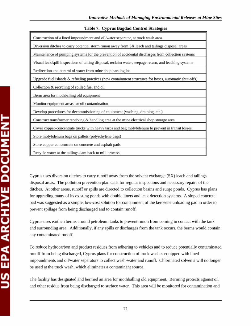
Innovative Methods of Managing Environmental Releases at Mine Sites
71
Construction of a lined impoundment and oil/water separator, at truck wash area
Diversion ditches to carry potential storm runon away from SX leach and tailings disposal areas
Maintenance of pumping systems for the prevention of accidental discharges from collection systems
Visual leak/spill inspections of tailing disposal, reclaim water, seepage return, and leaching systems
Redirection and control of water from mine shop parking lot
Upgrade fuel islands & refueling practices (new containment structures for hoses, automatic shut-offs)
Collection & recycling of spilled fuel and oil
Berm area for mothballing old equipment
Monitor equipment areas for oil contamination
Develop procedures for decommissioning of equipment (washing, draining, etc.)
Construct transformer receiving & handling area at the mine electrical shop storage area
Cover copper-concentrate trucks with heavy tarps and bag molybdenum to prevent in transit losses
Store molybdenum bags on pallets (polyethylene bags)
Store copper concentrate on concrete and asphalt pads
Recycle water at the tailings dam back to mill process
Table 7. Cyprus Bagdad Control Strategies
Cyprus uses diversion ditches to carry runoff away from the solvent exchange (SX) leach and tailingsdisposal areas. The pollution prevention plan calls for regular inspections and necessary repairs of theditches. At other areas, runoff or spills are directed to collection basins and surge ponds. Cyprus has plansfor upgrading many of its existing ponds with double liners and leak detection systems. A sloped concretepad was suggested as a simple, low-cost solution for containment of the kerosene unloading pad in order toprevent spillage from being discharged and to contain runoff.
Cyprus uses earthen berms around petroleum tanks to prevent runon from coming in contact with the tankand surrounding area. Additionally, if any spills or discharges from the tank occurs, the berms would containany contaminated runoff.
To reduce hydrocarbon and product residues from adhering to vehicles and to reduce potentially contaminatedrunoff from being discharged, Cyprus plans for construction of truck washes equipped with linedimpoundments and oil/water separators to collect wash-water and runoff. Chlorinated solvents will no longerbe used at the truck wash, which eliminates a contaminant source.
The facility has designated and bermed an area for mothballing old equipment. Berming protects against oiland other residue from being discharged to surface water. This area will be monitored for contamination and
Innovative Methods of Managing Environmental Releases at Mine Sites
72
procedures for decommissioning, washing, draining of equipment will be developed to prevent furthercontamination.
Copper concentrate trucks are covered with heavy tarps and molybdenum is bagged in polyethylene bags toprevent in transit losses to road ways (losses can become contaminated runoff). Molybdenum bags are storedon pallets and copper concentrate on concrete and asphalt pads in order to reduce contact with runoff.
Part of Cyprus's integrated approach is its wide variety of activities throughout its operations; another aspectof its integrated approach is the level of detail. The Cyprus pollution prevention plan clearly states projectdescriptions, rationale, and performance goal summaries for each suggested control measure. Goals includespercent volume reduction and target dates. The plan provides measures for tracking progress viaenvironmental steering committee meetings, tracking of construction projects through budgetary process,supervisors keeping monitoring logs, periodic management reviews, tracking assigned projects via employeeperformance reviews, and training of employees. Strategies identified include outlining the frequency ofroutine maintenance and inspections, and identifying what items should be inspected such as testing ofemergency backup systems, monitoring pump rates, pond and dam elevations, depth measurements of liquidpresent in collection systems, visually inspecting HDPE liners, checking pump performance by motoramperage readings, piping and sumps to ensure all systems are performing to design.
Valdez Creek Mine, Cambior Alaska, Inc, Cantwell, Alaska
The Valdez Creek Mine is a placer gold mine operated by Cambior Alaska and Camindex Mines, and islocated 110 miles south of Fairbanks, near Cantwell, Alaska. Mining in the Valdez Creek area has occurredsince 1903. The current pit has been in service since 1984.
In 1990-1991, operational changes occurred at the mine site. In order to access additional ore sourcesbeneath the active stream channel, Valdez Creek was diverted. A diversion dam was constructed upstream ofthe active pit. The dam impounds water, which then flows through the diversion channel approximately onemile until rejoining with the stream. The diversion channel is lined with a synthetic liner and rip-rap toprevent erosion and incision (downcutting) of the channel. The creek is then returned to its original channelbelow the mine, before entering the Susitna River.
To assist water management in the active area of the pit, the facility maintains two small diversion ditches oneither side of the valley above the mined area to intercept runoff before it reaches the pit. Water from thesediversion ditches flows to two settling ponds. The facility's diversion system is designed to control flowsproduced by up to a 25 year storm event. By utilizing the lined diversion channel for Valdez Creek and thetwo small diversion ditches and settling ponds, the impact to the downstream environment is minimized bythe reduction in turbidity and sedimentation in Valdez Creek caused by the mining operation.
Like many placer mines in Alaska, Cambior Alaska Inc, has used stream diversion techniques at the site. However, at this facility the stream diversion not only prevents stream discharges, but also improves access
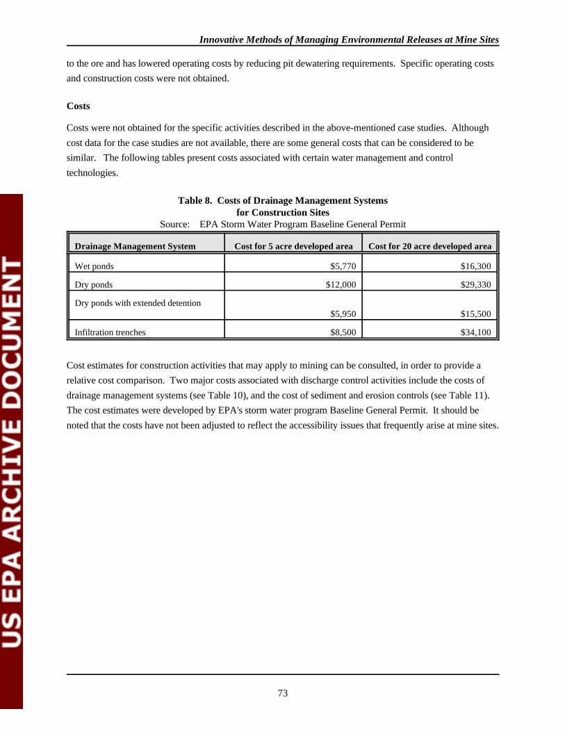
Innovative Methods of Managing Environmental Releases at Mine Sites
73
Drainage Management System Cost for 5 acre developed area Cost for 20 acre developed area
Wet ponds $5,770 $16,300
Dry ponds $12,000 $29,330
Dry ponds with extended detention$5,950 $15,500
Infiltration trenches $8,500 $34,100
Table 8. Costs of Drainage Management Systemsfor Construction Sites
Source: EPA Storm Water Program Baseline General Permit
to the ore and has lowered operating costs by reducing pit dewatering requirements. Specific operating costsand construction costs were not obtained.
Costs
Costs were not obtained for the specific activities described in the above-mentioned case studies. Althoughcost data for the case studies are not available, there are some general costs that can be considered to besimilar. The following tables present costs associated with certain water management and controltechnologies.
Cost estimates for construction activities that may apply to mining can be consulted, in order to provide arelative cost comparison. Two major costs associated with discharge control activities include the costs ofdrainage management systems (see Table 10), and the cost of sediment and erosion controls (see Table 11). The cost estimates were developed by EPA's storm water program Baseline General Permit. It should benoted that the costs have not been adjusted to reflect the accessibility issues that frequently arise at mine sites.
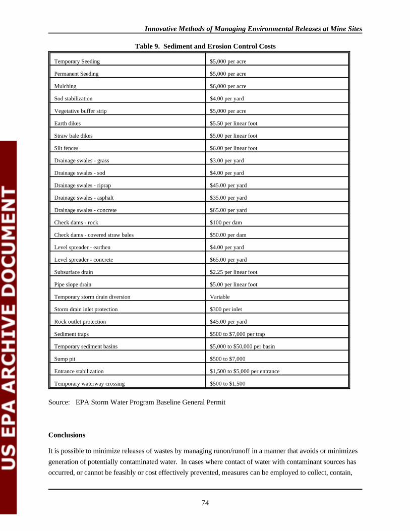
Innovative Methods of Managing Environmental Releases at Mine Sites
74
Temporary Seeding $5,000 per acre
Permanent Seeding $5,000 per acre
Mulching $6,000 per acre
Sod stabilization $4.00 per yard
Vegetative buffer strip $5,000 per acre
Earth dikes $5.50 per linear foot
Straw bale dikes $5.00 per linear foot
Silt fences $6.00 per linear foot
Drainage swales - grass $3.00 per yard
Drainage swales - sod $4.00 per yard
Drainage swales - riprap $45.00 per yard
Drainage swales - asphalt $35.00 per yard
Drainage swales - concrete $65.00 per yard
Check dams - rock $100 per dam
Check dams - covered straw bales $50.00 per dam
Level spreader - earthen $4.00 per yard
Level spreader - concrete $65.00 per yard
Subsurface drain $2.25 per linear foot
Pipe slope drain $5.00 per linear foot
Temporary storm drain diversion Variable
Storm drain inlet protection $300 per inlet
Rock outlet protection $45.00 per yard
Sediment traps $500 to $7,000 per trap
Temporary sediment basins $5,000 to $50,000 per basin
Sump pit $500 to $7,000
Entrance stabilization $1,500 to $5,000 per entrance
Temporary waterway crossing $500 to $1,500
Source: EPA Storm Water Program Baseline General Permit
Table 9. Sediment and Erosion Control Costs
Conclusions
It is possible to minimize releases of wastes by managing runon/runoff in a manner that avoids or minimizesgeneration of potentially contaminated water. In cases where contact of water with contaminant sources hasoccurred, or cannot be feasibly or cost effectively prevented, measures can be employed to collect, contain,
Innovative Methods of Managing Environmental Releases at Mine Sites
75
and treat the runoff. These activities can be accomplished by developing, implementing, and maintaining anintegrated approach to water management at a mining facility.
This report has briefly outlined a few case studies where many practices have been implemented. Actualfacility implementation of the reclamation and water management plans, however, was not investigated forthis study. Activities like those discussed in the case studies, as well as many other techniques, can beincorporated into existing facilities throughout the mining industry. Initial facility design consideringrunon/runoff controls is a good example of planning. In addition, one important aspect to success is the daily,routine implementation of the correct management practices.
Contacts: EPA Nonpoint Source Coordinators
Region 1 Region 6Bob Moorehouse Brad LambJack F. Kennedy Federal Building 1445 Ross AveBoston, Massachusetts 02203 Dallas, Texas 75202(617) 565 - 3545 (214) 655 - 6683
Region 2 Region 7Mack Henning Julie Elfving26 Federal Plaza, Room 813 726 Minnesota AveNew York, New York 10278 Kansas City, Kansas 66101(212) 264 - 2055 (913) 551 - 7475
Region 3 Region 8 Hank Zygmunt Carol RussellChestnut Building One Denver Place841 Chestnut Street 999 18th StreetPhiladelphia, Pennsylvania 19107 Denver, Colorado(215) 597 - 8429 (303) 293 - 1449
Chesapeake Bay Program, Region 3 Region 9 Lynn Shuyler Jovita E. Pajarillo410 Severn Ave, Suite 109 75 Hawthorne StreetAnnapolis, Maryland 21403 San Francisco, California 94105(410) 267 - 0061 (415) 744 - 2011

Innovative Methods of Managing Environmental Releases at Mine Sites
76
Region 4 Region 10Mary Ann Gerber Robert Moore345 Courtland Street, NE 1200 6th AveAtlanta, Georgia 30365 Seattle, Washington 98101(404) 347 - 2126 (206) 553 - 4181
Region 5 Idaho Operations Office, Region 10Tom Davenport Don Martin77 West Jackson Street 422 West Washington StreetChicago, Illinois 60604 Boise, Idaho 83702(312) 886 - 0209
References
American Mines Handbook 1991-1992.
Best Management Practices for Mining in Idaho, Idaho Department of Lands in Conjunction with Other Stateand Federal Agencies through the Idaho Mining Advisory Committee, November 16, 1992.
Cambior Alaska, Inc Response to EPA's September 1992 Draft Mine Site Visit Report, November 13, 1992.
Checklist for NEPA Reviewers - Non-Coal Mine Sites, Draft Final, prepared by Science ApplicationsInternational Corporation for U.S. Environmental Protection Agency, April 25, 1991.
Coastal Nonpoint Program, Program Development and Approval Guidance, Appendix B, Overview ofExisting National Efforts To Control Nonpoint Pollution, pages 37 - 40.
Controlling Urban Runoff: A Practical Manual for Planning and Designing Urban BMPs, Tom R. Schueler,Metropolitan Washington Council of Governments, Department of Environmental Programs, July1987.
Cyprus Bagdad Copper Corporation, Pollution Prevention Plan, Submitted to the Arizona Department ofEnvironmental Quality, Pollution Prevention Unit, December 1992.
Environmental Impact Report/Environmental Impact Statement for the Hayden Hill Project, Lassen County,California, Final, prepared by Steffen Robertson and Kirsten, Inc., for Lassen Gold Mining, Inc., TwoVolumes, State Clearing House No. 89020079, September 1991.
Environmental Management for the 1990s. Introduction to Evaluation, Design and Operation of PreciousMetal Heap Leaching Projects. Editors Dirk J.A. van Zyl, Ian P.G. Hutchinson, Jean E. Kiel,published by Society of Mining Engineers, Inc. Littleton, Colorado, 1988.
EPA Journal, "The Problem: Introducing NPS Water Pollution, We Can't Write Permits on Parking Lots",Robert Griffin, Jr., pages 6 - 9, November/December 1991.
Idaho Nonpoint Source Management Program, Idaho Department of Health and Welfare, Division ofEnvironmental Quality, Water Quality Bureau, prepared by Stephen B. Bauer, 1989.
Managing Nonpoint Source Pollution, Final Report to Congress on Section 319 of the Clean Water Act(1989), U.S. Environmental Protection Agency, Office of Water, Doc No EPA-506/9-90, January1992.
Mining Site Visit: LTV Steel Mining Company, U.S. Environmental Protection Agency, June 1992.
Innovative Methods of Managing Environmental Releases at Mine Sites
77
Mine Site Visit: Valdez Creek Mine, Cambior Alaska Incorporated, Draft, prepared by Science ApplicationsInternational Corporation, for U.S. Environmental Protection Agency, September 1992.
Mining Engineering, Industry Newswatch "Amax Gold Wins DuPont/Conoco Environmental Award" page40, December, 1992.
Mining Engineering, "Gold Mining From the Perspective of a Chief Executive Officer", page 987, August,1992.
Mining Engineering, U.S. and International Mineral News Briefs, January, 1992, page 40.
Noncoal Reclamation, Audit Report, Abandoned Mine Land Program, Office of Surface Mining Reclamationand Enforcement, U.S. Department of the Interior, Office of Inspector General, Report No. 91-I-1248,September, 1991.
Nonpoint Source Control Program, Chapter 10, pages 161 - 166, document title not specified.
Northern Miner, "Amax Gets Permit for Hayden Hill After Two Year Wait," John Kilburn, page 1, ISSN0029-3164, November 25, 1991.
Report To Congress, Wastes From the Extraction and Beneficiation of Metallic Ores, Phosphate Rock,Asbestos, Overburden from Uranium Mining, and Oil Shale, U.S. Environmental Protection Agency,Office of Solid Waste, December 31, 1985.
Skillings Mining Review, "Amax Gold and U.S. Gold To Go Ahead with Hayden Hill," ISSN 0037-6329,page 13, October 21, 1989.
SME Mineral Processing Handbook, N.L. Weiss, Volume 2, published by Society of Mining Engineers,1985.
State Regulation of Mining Wastes: Current State of the Art, Draft, Environmental Law Institute, April,1992.
Storm Water Management for Construction Activities, Developing Pollution Prevention Plans and BestManagement Practices, U.S. Environmental Protection Agency, Office of Water, EPA 832-R-92-005,September 1992.
Storm Water Management for Construction Activities, Developing Pollution Prevention Plans and BestManagement Practices, Summary Guidance, U.S. Environmental Protection Agency, Office of Water,EPA 833-R-92-001, October, 1992.
Storm Water Management for Industrial Activities, Developing Pollution Prevention Plans and BestManagement Practices, U.S. Environmental Protection Agency, Office of Water, EPA 832-R-92-006,September 1992.
Tailings Management: Problems and Solutions in the Mining Industry, G.M. Ritchy, Process Metallurgy 6,published by Elsevier, 1989.
Innovative Methods of Managing Environmental Releases at Mine Sites
78
Attachment
Techniques for Management and Control of Runoff
Management and Control of Runoff
Effective practices for the management and control of runon/runoff are also known as best managementpractices, or BMPs. BMPs can be defined as measures or practices used to reduce the amount of pollutionentering surface water, air, land, or groundwater, and may take the form of a process, activity, or physicalstructure. BMPs may include schedules of activities, prohibitions of practices, maintenance procedures, andother management practices to prevent or reduce discharges of pollutants to waters of the United States. BMPs include treatment requirements, operating procedures, and practices to control plant site runoff,spillage or leaks, waste disposal, drainage from raw material storage or other disturbed areas.
There are two ways to reduce the potentially contaminated discharges from a facility. First is avoidance; it isoften preferable to minimize contact of water with contaminant sources. Second is to reduce the volumes ofwastewater and pollutant concentrations in the wastewater. BMPs applicable to mine site discharges can bedivided into three general areas: (1) construction/reclamation, (2) management and housekeeping, and (3)treatment. Specific techniques in each of these areas include:
Construction/Reclamation Techniquesdiversion ditches and drainage systemsrip-rapdikes & bermsgrading or terracingcollection basinscapping or sealing vegetation & mulchingsilt fences
Management & Housekeeping Techniquesproper handling proceduresimmediate spill cleanupinspectiontraining & educationroutine maintenancecomprehensive pollution prevention planperiodic reviews of systems
Treatment Techniquessedimentation basinsoil/water separatorsneutralizationartificial wetlands
In a hierarchy of preferred strategies, it is generally most desirable to avoid contact with exposed materials. This is done by preventing runon from flowing onto the site or coming into contact with individualcontamination sources (using practices such as dikes or berms). Second if contamination does occur, BMPs
Innovative Methods of Managing Environmental Releases at Mine Sites
79
can be used to promote infiltration and reduce contaminant loadings. Finally, runoff can be collected inbasins for sedimentation or treated by other means. A brief discussion of the variousconstruction/reclamation techniques and treatment systems follows.
Construction/Reclamation Techniques
Construction/reclamation techniques are divided into structural, vegetative, and capping/sealing practices inthe following subsections.
Structural Practices
Discharge diversions provide the first line of defense in preventing the contamination of discharges and areinstalled to divert flow, store flow, or limit runoff. Diversion structures are often designed to prevent waterfrom crossing disturbed areas where contact may occur between run-on and significant materials. Thesemeasures may be particularly effective for former mining areas and stockpiles. Measures to prevent contactinclude diversion structures, such as dikes, berms, or ditches to channel runon away from or around apotential contaminant source. Materials used to construct dikes, curbs, and berms include earthen materials(eg. clay), concrete, synthetics, metal or other low permeability substances. Additionally, diversion structurescan be used to collect or divert waters for later treatment, if necessary. The usefulness of diversion measuresare limited by such factors as the size of the area to be controlled, and volumes of runoff to be diverted.
Drainage Systems
Drainage systems are designed to control drainage by redirecting channel flow, slowing velocity andcontrolling volume, in order to improve or prevent infiltration or reduce erosion. A drainage system mayconsist of structures such as subsurface drains, leachate collection systems, etc. Drainage systems may belined with grass, rip-rap, asphalt, or concrete.
Drainage systems are effective when used in conjunction with outlet velocity dissipation devices designed toslow the flow of water discharged from a site in order to lessen the amount of erosion. Some examples of themore effective velocity dissipation devices include check dams, rock outlet protection, and level spreaders. These are discussed below.
Check Dams. Check dams are small temporary dams constructed across swales or drainage ditches to reducethe velocity of runoff flows, thereby reducing erosion and potential failure of the swale or ditch. This slowingalso allows sediments to settle. Materials used to construct check dams include: rock, timber, sandbags filledwith pea gravel, and straw bales.
Check dams also may be used as a passive treatment mechanisms, particularly for acid mine drainage. Byincorporating alkaline containing materials (i.e., limestone rock or mix materials with neutralizing propertieswith pea gravel in the sand bags), acid mine drainage can be treated. Additionally, incorporating a sorbentinto the sand bags will assist in absorbing organics.

Innovative Methods of Managing Environmental Releases at Mine Sites
80
Rock Outlet Protection. Rock protection at the outlet of culverts, channels, or ditches reduces the depth,velocity, and destructive energy of water. As with check dams, rock outlet protection may also be used as apassive treatment mechanism by using rocks containing limestone or other alkaline materials to neutralizeacidic discharges.
Level Spreaders. Level spreaders are outlets for dikes and diversions consisting of an excavated depressionconstructed at zero grade across a slope. Level spreaders convert concentrated high velocity, concentratedflows into diffuse runoff that is released onto areas stabilized by existing vegetation (thereby promotinginfiltration).
Infiltration Controls
Infiltration controls are surface or subsurface measures such as trenches and basins, that promote rapidinfiltration of precipitation and runoff. Infiltration devices can be used to reduce discharge volumes andprovide for groundwater recharge. Treatment may be incorporated within the trench/basin. Limestone orsoda ash can be used for neutralization of potentially acidic discharges.
Straw bale dikes, silt fences, and brush barriers are temporary barriers used to intercept sediment in runofffrom small areas of disturbed soil. Silt fences consist of geotextile fabric (filter cloth). Silt fences aregenerally more effective in preventing discharges of sediment than straw bales. Brush barriers are temporarysediment barriers composed of tree limbs, weeds, vines, root mat, soil, rock, and other cleared materialsplaced at the toe of a slope. A brush barrier is effective only for small drainage areas, usually less than 1/4acre, where there is sheet flow, and the slope is minimal.
Vegetative Practices
Vegetative practices involve covering or maintaining an existing cover over soils. The cover may consist ofgrass, trees, vines, shrubs, bark, mulch and/or straw. A vegetative cover reduces the potential for erosion at asite by reducing flow through infiltration. Vegetative practices include permanent seeding, mulching, soilconditioning, contouring or grading, and the use of vegetative strips.
Permanent seeding stabilizes the soil to reduce sediment in runoff from the site. Mulching is most effectivewhen used in conjunction with a permanent seeding program. When permanent seeding is not feasible,exposed soils can be stabilized by applying plant residues or other suitable materials to the soil surface. Soilconditioning or topsoiling may be necessary to improve the area on which permanent vegetative practices willbe established. Conditioning is often necessary where soil is of poor quality. Surface contouring createshorizontal grooves, depressions, or steps that run with the contour of the land. Slopes may also be left in aroughened condition to reduce discharge flow and promote infiltration.
In some cases, revegetation of an entire site is unfeasible. In such cases, revegetation in buffer strips may bea more appropriate control measure. Vegetative buffer strips are strips of vegetation at the top and bottom of
Innovative Methods of Managing Environmental Releases at Mine Sites
81
the slope of a disturbed site. Vegetative buffer strips can slow runoff flows at critical areas, decreasingerosion and promoting sedimentation.
Capping and Sealing
Elimination of a pollution source through capping, plugging, or sealing contaminant sources may be the mostcost effective control measure for discharges from former and inactive mining operations, including tunnels,adits, and surface mine workings as well as from waste rock and tailings.
Capping/sealing is designed to prevent infiltration, as well as to limit contact between runoff and potentialsources of contamination. Ultimately, capping should reduce or eliminate the contaminants in discharges. Inaddition, by reducing infiltration, the potential for seepage and leachate generation may also be lessened. This practice could be applicable to pits, waste rock piles and tailings piles (particularly acid producingmaterials). Cap/liner materials include soil, clay, and/or synthetics.
Plugging of mine adits provides control and reduction of waste generation and migration. Once the adits areplugged, water will rise and flood the void space behind the plugs. Inundation of high sulfide mineral zonesbehind the plugs will prevent or reduce the chemical reactions that generate acid and release metals from theminerals, thereby reducing the contamination of water within the mineralized zones. Plugs will serve toprevent surges of water, sludge, and sediment from tunnels to surface waters, as well as preventing theintroduction of precipitation into subsurface areas.
Leachate Control and Collection
Leachate control and collection techniques may be appropriate for managing leachate/seepage from mineadits, mine waste units, and heap and dump leach piles. Leachate collection and removal systems arecommonly sand drainage layers, synthetic drainage nets (i.e., geonets) or granular drainage layers withperforated collection pipes installed in gravel-filled trenches above the liner at the base of the disposal unit. The collection system is drained by gravity to a sump or series of sumps or to storage tanks or ponds fromwhich the leachate is withdrawn for treatment or disposal.
Treatment Techniques
Treatment practices are those controls that result in a reduction of pollutant concentrations in discharges. Most treatment systems are based on relatively simple passive technologies such as settling of solids, andneutralization, and are designed to collect and temporarily store on-site runoff to meet the demands of a 10-year, 24-hour storm, or 25-year, 24-hour storm event.
Innovative Methods of Managing Environmental Releases at Mine Sites
82
Discharge Detention Structures (Sediment ponds)
Discharge detention structures can achieve a high removal rate of sediment and metals. Additionally, pondshave the capacity to promote degradation of organic contaminants. Detention ponds may also act as surgeponds to reduce or eliminate discharges during major storm events or high snow melt periods.
Organic Treatment
Biological processes are typically used to remove organic contaminants. These processes can includeanaerobic filters, anaerobic sludge bed reactors, aerated lagoons, rotating biological conductors and tricklingfilters. Organic removal can also be effectively accomplished by other physical/chemical treatment methods,including air and steam stripping, carbon absorption, and oxidation with calcium hypochlorite or ozone.
Chemical Treatment for Metals
Physical/chemical treatment can also be accomplished in the detention structures described above. This mostcommon type of chemical/physical treatment involves the addition of lime or other caustics to provideneutralization and/or precipitation of metals. Typically, pH levels of 9 to 12 standard units are required toachieve desired precipitation rates. Acid addition may be necessary to reduce the pH if discharge to surfacewaters is necessary. Polymer addition can also be used to enhance settling.
Lime and calcium fluorophosphate admixing provide an alkaline environment that helps to prevent bacterialoxidation of pyrites in waste materials while neutralizing the pyritic material that is oxidized. Admixing ismost effective when used in infiltration trenches filled with different gradients of limestone or soda ash.
Oil/Water Separation
Oil and water separation can be accomplished by use of an API or similar type of treatment device which actsto skim oil and settle sludge. Passive oil/water separators constructed of concrete can also be used to separateoil and water by gravity separation. Absorbent booms are also sometimes used to collect any oil contained inrunoff.
Artificial Wetlands
Artificial wetlands are designed to maintain a permanent pool of water. Artificial wetlands will be most cost-effective when used to control runoff from larger, heavily developed sites. Artificial wetlands are created toprovide treatment. Artificial wetlands are currently being researched by the Bureau of Mines as a means ofmitigating acid mine drainage.

Innovative Methods of Managing Environmental Releases at Mine Sites
83
4.2 CYPRUS BAGDAD POLLUTION PREVENTION PLAN
Arizona has established a multifaceted pollution prevention program to encourage generators of hazardouswaste to prepare a Pollution Prevention Plan. The Company issued a Plan in December 1992 that integratespollution prevention planning for the entire facility with existing emergency response plans, such as theirSpill Prevention Control and Countermeasures (SPCC) Plan and others.
The State encourages companies to prepare pollution prevention plans by reducing environmental permitfiling fees 50 percent. Cyprus estimates that this amounts to a saving of $10,000 to $20,000 per year. Asstated in the Plan, Cyprus is committed to identifying, measuring, and reducing pollution from its facilities. While acknowledging the need to use chemicals in many phases of their operation, they have obligatedthemselves to reduce the amount of hazardous substances used and hazardous wastes generated.
According to a facility representative, Cyprus management initiated preparation of the Pollution PreventionPlan in response to the State requirement. The Company Vice President on site issued a statement promotingthe importance of pollution prevention and requesting full employee support. Cyprus Bagdad's Plan wasdesigned as a workforce based plan with the environmental department acting more as a facilitator in theprocess. The Plan was implemented through top-down and bottom-up training. Management was trained inpollution prevention concepts and an environmental steering committee was formed. The environmentalsteering committee coordinated employee training in pollution prevention and enlisted their help at theirregular safety meetings in implementing the Plan. Both management and employees worked to identifyprojects. The facility's environmental staff conducted an internal audit for regulatory compliance and maderecommendations to management. Their current function is to help management setup a tracking system fornew ideas submitted by the employees and to monitor the status of ongoing projects. According to Cyprus,they are receiving one or more ideas each week. A status report was submitted to the State in July, 1993.
Plan Components
The Cyprus Pollution Prevention Plan was structured as a composite of existing plans and new materialcombined into three new plans. The three plans, prepared by the Mine, Mill (with the SX-EW plant as a sub-area), and Community Services operations, were designed to encourage departmental initiatives, identifyingprojects within their area that support the Company's goal of pollution prevention. Projects identified for theCommunity Services Operation are not included in this report since they are not related to mining activity. For existing plans (e.g. SPCC plan) best management practices and waste minimization goals were alsoidentified. The general goals of the Pollution Prevention Plan, as stated by Cyprus are: (1) inventory allchemical and petroleum products at each location; (2) identify and develop substitute productrecommendations; (3) develop methods for mass balance on chemical and petroleum products, and; (4)develop employee training and heighten awareness. New contract language with contractors, vendors, orservice companies requires compliance with Cyprus Bagdad's Pollution Prevention Plan.
In this summary, projects identified in each operation's plan are grouped into one of two categories; thoseunique to mining and those best described as good housekeeping. The following text summarizes these
Innovative Methods of Managing Environmental Releases at Mine Sites
84
projects grouped by these two categories. Within these categories, the project's orientation is identified (e.g.source reduction, spill prevention, etc.). Descriptions of the projects include information as it is availablefrom the Plan in the individual operation's description. Where applicable, planned completion dates andregulatory requirements are given.
Projects Unique to Mining
Of the projects identified as part of the Plan, none are uniquely related to the operation of the mine. However,one project planned for the mill and three projects planned for the Solvent Extraction-Electrowinning (SX-EW) plant can be considered unique to extraction and beneficiation operations.
Mill personnel have observed that the zinc liners in the secondary crushers could be recycled more effectively. While zinc mantle liner pieces are currently recycled at the facility (the method of recycling was notdiscussed), they sometimes get misplaced in the scrap metal bin used for steel. According to Cyprus, morecareful segregation could reduce 1993 zinc purchases as much as 20 percent of those in 1992 (up to 1,900pounds at $0.87 per pound).
Two of the projects are identified for the SX-EW facility involve upgrading solution impoundments andadding leak detection systems. The pregnant leach solution (PLS) surge pond is to be upgraded to double-lined containment with a leak detection system. The raffinate pond will be upgraded by adding a leakdetection system. Work on the PLS surge pond and the raffinate pond are required for compliance withArizona Department of Environmental Quality (ADEQ) aquifer protection limits. A third project is torecover kerosene exiting the solvent extraction stream (the method was not specified). Personnel areinvestigating installation of a recovery system for entrained organics in the raffinate stream.
Good Housekeeping Projects
Most of the projects proposed by the plan are good housekeeping measures. The predominant sourcereduction techniques employed are product changes and source control. Recycling and waste treatment arealso employed in addition to source reduction. Of the 25 good housekeeping measures, the mine identifiedseven, the mill identified eleven, and the SX-EW plant identified seven. All of the practices could potentiallybe applied at other mine sites.
Mine
Of the seven projects identified by the mine, some are currently underway. Fuel spillage will be controlled(source control) around the fuel islands and new re-fueling procedures are to implemented. This project callsfor design and installation of a containment structure for hoses and an evaluation of automatic shut-offs. Spilled fuel and oil will be collected and recycled whenever possible. Cyprus also plans to site, design, andconstruct a bioremediation facility for petroleum contaminated soil. According to the Plan, soil will bereturned to the waste dump or used as landfill cover when hydrocarbon contamination drops below the currentregulated level of 100 ppm.
Innovative Methods of Managing Environmental Releases at Mine Sites
85
The mine is investigating using bulk containers instead of 55 gallon drums for lubricants to eliminate residualproduct in the drums. Lubricant suppliers will be contacted to determine if bulk reusable containers areavailable and written procedures will be developed for their use. Other projects call for elimination ofchlorinated solvents in the truck wash facility. The mine shop will reduce use of chlorinated solvents 25percent. As part of this activity, the sedimentation basin will be closed and remediated and a linedimpoundment with an in-line oil/water separator will be built. Storm drains from the mine shop parking lotwill be controlled and diverted to the impoundment. Water will be redirected to the mine (additional detailson this project were not provided in the Plan).
Another project to be implemented will be selecting a storage site and developing written procedures fordecommissioning used equipment (e.g. washing, draining fluids, etc.). The storage area is to bermed andmonitored for oil contamination. Finally, a transformer receiving and handling area at the mine electricalshop storage area will be built.
Mill
Mill projects focus on recycling and source reduction. Like the mine, some of these are intended to meetADEQ regulatory requirements. The Company is asking lubricant suppliers to recycle spent products. Aspart of this project, the purge and collection system for oil and grease will be revised to use bins. The currentsystem was not described. Freon from refrigeration units will be recycled to minimize evaporation ofchlorinated compounds. Cleaning solvents in the maintenance area will also be recovered and recycled. Safety Solvent will be filtered and recycled; this should reduce purchases by 20 percent.
The maintenance shop will recover and recycle metal scrap. Bins for metal were placed in the shop area. Cyprus estimates that 10,000 lbs of scrap bolts etc. should be collected annually. Scrap metal is recycled off-site.
Truck washes will collect hydrocarbons and sediment. Hydrocarbons will be recycled whenever possible orsent to the bioremediation facility. The warehouse is also investigating options to sell paper and cardboard toa recycling plant and plans to reuse packing materials where possible.
Examination of source reduction opportunities have resulted in a number of projects. The mill uses lime tocondition water reclaimed from the tailings impoundment. By adjusting the pH of feed water from 10.5 to10.0, lime consumption will be reduced 5 percent. This will result in a minor cost savings and should notpose a scaling problem. In the past, the mill has added chlorine to tailing seepage water to prevent excessivebiogrowth; 800 pounds of calcium hypochlorite was added in 1992). Cyprus will discontinue this practicesince no benefit was observed. Another goal for source reduction is the elimination of chlorinated solvents. Some chlorinated solvents have already been eliminated from stock (e.g. trichloroethane was eliminated), andothers were reduced 50 to 70 percent (usage was not specified). Storage and use of toluene-based spray paintwill also be discontinued. Hand painting with non-toluene based paint will be encouraged.
Innovative Methods of Managing Environmental Releases at Mine Sites
86
The mill's laboratory inventoried their chemicals on hand. A selected stock of chemicals have been, or willbe, reduced or eliminated. Following a January 1992 inventory, a licensed chemical disposal firm removed122 chemical species from the laboratory. Additional chemicals are to be removed. The laboratory alsoeliminated use of xylenes to dilute analysis oils and substituted kerosene.
SX-EW Plant
Projects at the SX-EW plant are intended to control surface contamination and encourage source reduction. Several of the projects at the facility are designed to meet ADEQ requirements. The Flood Basin will beupgraded by installing double-lined containment with a leak detection system. The facility also plans to builda containment structure around the kerosene unloading pad to contain any spills which occur duringunloading. The acid storage area will be relocated and upgraded so that drainage would enter the leach feedsolution. Details on the design were not specified. Spills outside the Electrowinning (EW) facilities, andfrom the sulfuric acid storage tanks, will report to the raffinate pond in the future. A variety of source reduction projects are underway. To eliminate empty waste drums and the need fordisposal on site, Cyprus is investigating the use of recyclable containers for bulk chemical delivery. Thelaboratory is revising their analytical techniques to reduce reagent consumption. For example, potassiumiodide consumption could be reduced 60 percent each year by optimizing the short iodide method for copperanalysis. Atomic absorption and chloride colorimetric methods for copper analysis will be investigated asreplacements for the short iodide method.
Costs and Benefits
According to a facility representative, the current costs associated with implementing the Plan exceedsavings. Cyprus expects that the benefits of the program to equal the costs in the long term. The search forsubstitutes to replace chlorinated solvents and the costs for disposal of these existing solvents has itsassociated costs. When the chlorinated solvents are replaced, these costs are expected to be reducedsubstantially. Environmental benefits are realized by containing process solutions in lined impoundments andbioremediation onsite. The potential to reduce costs by recycling zinc liners, scrap metal, and other materialand the reduction or elimination of chemicals such as lime, calcium hypochlorite, and chlorinated solvents arealso incentives. Current savings are in the form of incentives from the State for having prepared the Plan. The Company estimates they are saving between $10,000 and $20,000 in State hazardous waste disposal feesas a result of a 50 percent discount on these fees (the type and volume of wastes transported off site were notspecified).
Summary and Conclusions
The Cyprus Bagdad Copper Company prepared an integrated Pollution Prevention Plan. This wasaccomplished and continues to evolve with the support of Company management and individual employees. Based on implementation of all the Plan's activities, information on the inventory and mass balance of all
Innovative Methods of Managing Environmental Releases at Mine Sites
87
chemical and petroleum products would provide a solid basis to organize and focus future projects. A portionof the Plan consists of other plans (e.g. Spill Prevention Control and Countermeasures) required at mine sitesas part of State regulations. These Plans are integrated into the Pollution Prevention Plan and themselvescontain Best Management Practices.
The approach used by Cyprus of evaluating all operations is sound. Cyprus is not only reducing itsenvironmental liability, but may also reduce its operating costs.
Phone Contacts
Cyprus Bagdad Copper CorporationColleen D. Kelly (602) 633-2241, Extension 204.
Comments
The U.S. Bureau of Mines and the Cyprus Minerals Company submitted comments to EPA on an earlier draftof this document.
EPA Response to Comments
The U.S. Bureau of Mines submitted comments. These have been responded to as appropriate.
EPA Response to Cyprus Comments
Comment 1: The introduction implies that there is uncertainty as to whether or not pollutionprevention/waste minimization is currently practiced in the mining industry.
Response: EPA believes that the introduction clearly states that the mining industry is currently practicingforms of pollution prevention/waste minimization. The purpose of these reports is to identify practicescurrently in use at mine sites, and encourage their use where ever possible.
Comment 2: The Background section leaves the pejorative implication that the only reason a pollutionprevention plan was prepared was that it was required by the State and makes a point that it was notconceived and prepared as part of the environmental program.
Response: The text has been amended to reflect the fact that Cyprus went to considerable lengths to involveits workforce in the preparation and implementation of it's plan. EPA is aware that the submittal of such aplan is a requirement established by the state. EPA is not implying however, that Cyprus prepared the planonly because it was a regulatory requirement.
Comment 3: Section 3: Cyprus Bagdad deliberately structured its Plan for each separate area as separateplans. ADEQ disagreed with this approach.
Response: Text has been changed to reflect this position.
Comment 4: Section 3: Cyprus has gone beyond notice to contractors, vendors, and service companies. Language has been inserted into their contracts to require them to comply with the Plan.
Response: Text has been changed to reflect this information.
Innovative Methods of Managing Environmental Releases at Mine Sites
88
Comment 5: Section 3: Cyprus sends its scrap metal off-site for recycling. Reference to ore in this section isunclear.
Response: Text has been changed to reflect this information.
Comment: Section 3: Page 4 states that truck washes collect hydrocarbons and product residuals. Onlyhydrocarbon residuals and sediment are collected. The sediment is not recyclable.
Response: Text has been changed to reflect this information.
Comment: Section 4: The summary and conclusions section does not seem to offer any summary andconclusions.
Response: EPA believes this section adequately summarize the Cyprus Bagdad Copper Corporation'sPollution Prevention Plan.
Comment: Section 4: The summary erroneously states that Bagdad is not in compliance with existingArizona environmental regulations.
Response: Text has been changed to reflect this information.
Comment: Section 4: The discussion of cost savings appears out of place. Cyprus expects the benefits ofthe program to equal the costs in the long term.
Response: The discussion of costs and benefits has been moved from the Summary to a new subsection inChapter 3.