Embed Size (px)
Citation preview
Chemical and Process Engineering 2018, 39 (1), 15–31
DOI: 10.24425/119096
POTENTIAL DESIGN IMPROVEMENTS OF A REVERSE FLOW
MINI-CYCLONE WITH A TANGENTIAL INLET
Tadeusz Dziubak∗
Faculty of Mechanical Engineering, Military University of Technology,ul. Gen. Witolda Urbanowicza 2, 00-908 Warsaw, Poland
This paper presents an effect of general dimensions of a reverse flow mini-cyclone with a tangential in-let on its separation efficiency. Several mini-cyclone design modifications are presented and evaluatedfor use in the air filtration systems of motor vehicles. Local design improvements of three componentsof a reverse flow mini-cyclone with a tangential inlet D-40 of an air filter fitted in an all-terrain ve-hicle engine were introduced. An asymmetric curvilinear shape of an outlet port was used instead ofa symmetrical shape. An outlet vortex finder inlet port shape was streamlined, and a cylindrical outletvortex finder of the cyclone was replaced with a conical one. Experimental evaluation of the effectsof the design improvements of mini-cyclone on its separation efficiency and performance as well asflow resistance was carried out. Separation efficiency of the cyclone was determined using the massmethod as a product of dust mass retained by the mini-cyclone and supplied to the mini-cyclone ina specified time. Separation performance of the cyclone was determined as the largest dust particledz = dzmax in a specific test cycle in the cyclone outlet air stream. A polydisperse PTC-D test dust usedin Poland, a substitute for AC-fine test dust was used. Dust concentration at the mini-cyclone inlet waskept at 1 g/m3. The size and total number of dust particles in the air stream at the outlet of the originalmini-cyclone and at the outlet of the improved mini-cyclone was determined using a particle counter.
Keywords: air filter, mini-cyclones, separation efficiency, separation performance, flow resistance,dust particle size distribution
1. INTRODUCTION
A supply of a dust-free inlet air to internal combustion engines of motor vehicles and machines to reducefriction and improve machine life has always been a major operational and design issue, in particularfor vehicles operating in heavy dust conditions (approx. concentration above 1 g/m3). The conditionsgenerally apply to special military vehicles (tanks, land attack vehicles, self-propelled guns and specialpurpose vehicles) with high-power diesel engines at a maximum air demand Qeng over 1 kg/s, e.g. Qeng =
1.21 kg/s, (3400 m3/h) for T-72 tank engine, Qeng = 2.15 kg/s (6000 m3/h) for Leopard 2 tank engine(Durst et al., 2005) and Qeng = 5.36 kg/s (15000 m3/h) for Abrams tank engine (Honeywell International,2000). For dust level concentration s = 1 g/m3, often observed in vehicle use on the testing grounds, theengines 0.94 g/s, 1.67 g/s and 4.15 g/s of air, respectively (Dziubak, 2009).
Two-stage air filters with a multi-cyclone and a porous screen (a filter element usually made of paper) areoften used to remove the high amount of dust with particle size < 100 µm (Baczewski and Hebda, 1992;Cenrtisep Air Cleaner, 2004; Durst et al., 2005; Dzierzanowski et al., 1985) from the air stream.
∗ Corresponding author, e-mail: [email protected] http://journals.pan.pl/dlibra/journal/98834

T. Dziubak, Chem. Process Eng., 2018, 39 (1), 15–31
The multi-cyclone is a unit including up to several hundred liners of the diameter up to D = 40 mm, alsocalled mini-cyclones (as distinct from industrial cyclones, go with internal diameter of D= 250−3000 mm),arranged side-by-side in parallel on two common perforated plates (top and bottom). The cyclones usedin motor vehicles achieve up to 98% separation efficiency (Baczewski and Hebda, 1992; Cenrtisep AirCleaner, 2004; Dziubak, 2010; Dziubak, 1995). During the 8-hour operation of T-72 tank engine in testingground conditions, the multi-cyclone may capture over 25 kg of dust, which is further removed by theejector suction system (Dziubak, 2012; Dziubak, 2000).
High mini-cyclone performance, determined by a high separation efficiency φ and low flow resistance∆p, increases with an air flow rate and − general dimension ratio (e.g.: H/D, D/dw, h/dw, a/b, Aw/A0)
carefully determined based on many years of research (Hoffmann et al., 1991; Juda, 1968; Kabsch, 1992;Swift, 1986; Warych, 1998). The research showed a relation between general dimensions of the mini-cyclone and allowed to determine the effect of different dimensions on separation efficiency and flowresistance, as well as the typical range of geometrical parameters (a ratio of general dimensions) for whichthe mini-cyclone achieves optimum performance, i.e. maximum efficiency and minimum pressure drop.As shown in an example (Fig. 1), the changes in separation efficiency φc and coefficient of flow resistanceξc as a function of dimensionless ratios Aw/A0 and H/dw, the optimum values for those parameters rangefrom 1.5–2 to 7–9, respectively (Juda, 1968).
a) b)
Fig. 1. Separation efficiency φc and coefficient of flow resistance ξc of mini-cyclones as a function of:a) with a tangential inlet Aw/A0 and b) with a spiral inlet design H/dw parameter (Juda, 1968)
The coefficient of flow resistance ξc is defined by the following relation (Juda, 1968):
ξc =2∆pc
ρa ·υ20
(1)
The use of the above data in design of mini-cyclones guarantees a relatively high separation efficiency ofmicron-size particles from inlet air supplied to internal combustion engines.
Research on the improvement of aerosol particle separation efficiency in mini-cyclones and limiting theresistance of air flow via design modification without changes in general dimensions is still being car-ried out. The methods to improve mini-cyclone efficiency presented in literature (Dzierzanowski et al.,1985; Jo et. al., 2000; Jung et al., 2004; Kabsch, 1992; Lim et al., 2003; Lim et al., 2004; Yoshida etal., 2005; Zhu et al., 2001), although verified by laboratory tests, have not been verified in practice, thusadditional analyses and tests are required. Numerical tests with CFD software are commonly used (Azadiand Azadi, 2012; Bernardo et al, 2006; Chu et al, 2011; Cortés and Gil, 2007; Jiao et al, 2006; Karagozet al., 2013; Kobyłecki, 2011; Krasinski, 2007; Liu et al., 2006; Sakura and Leung, 2015; Wang et al.,
http://journals.pan.pl/dlibra/journal/9883416

Potential design improvements of a reverse flow mini-cyclone with a tangential inlet
2006; Wasilewski and Duda, 2016; Winfield et al., 2013; Qian et al., 2006) to assess cyclone efficiency,although experimental testing is considered the most reliable method (Baczewski and Hebda, 1991/92;Dzierzanowski et al., 1985; Dziubak, 2010; Jo et al., 2000; Lim et al., 2003; Wasilewski and Duda, 2016;Yoshida et al., 2005; Zhao, et al., 2004).
This paper presents an experimental assessment of separation efficiency, separation performance and flowresistance of modified designs of the reverse flow mini-cyclone with a tangential inlet used in off-roadvehicle air filter’s multi-cyclone.
2. POTENTIAL IMPROVEMENT OF CYCLONE SEPARATION EFFICIENCY
The improvements in efficiency of the reverse flow mini-cyclone with a tangential inlet (separation effi-ciency or reduction of flow resistance), without affecting general dimensions have been subject of manyresearch works, which led to the following three methods of cyclone modification:
• modification of inlet stream feed method to the cylindrical cyclone section (Cortés and Gil; Dzierza-nowski et al., 1985; Lim et al., 2003; Yoshida et al., 2005; et al., 2004),
• modification of outlet line shape to reduce flow resistance (Kabsch, 1992; Lim, et al., 2004),
• non-standard modified designs (Jo, et al., 2000; Jung et al., 2004, Zhu et al., 2001).
Dzierzanowski et al. (1985) showed that the symmetrical inlet nozzle with rounded edges, commonly usedin reverse flow mini-cyclones with a tangential inlet results in adverse cross-sectional mass distributionof dust particles (Fig. 2a) that may affect separation efficiency. Replacing the symmetrical inlet with anasymmetrical inlet (Fig. 2b) or use of guide vanes ‘K’ (Fig. 2c) directly upstream of the inlet will directly(at the inlet) cause a significant amount of dust distributed close to the external wall of cylindrical sectionof a mini-cyclone to facilitate dust separation from air and improve separation efficiency.
Fig. 2. Cross-sectional dust particle size distribution – flat inlet: a) symmetrical, b) asymmetrical, c) symmetricalwith guide vanes um – relative dust fraction in the inlet air stream (Dzierzanowski et al., 1985)
All available research studies show that the highest share (75−90%) in total gas pressure losses for thecyclone are the losses at the inner cyclone vortex finder (outlet line) (Kabsch, 1992; Lim et al., 2004).There are several inner cyclone vortex finder solutions available to reduce flow resistance. Fig. 4 showssome examples.
Replacing a standard cylindrical outlet vortex finder with a conical outlet vortex finder while maintainingthe inlet port diameter dw and introducing a streamlined outlet vortex finder inlet port (Fig. 3b, c) maysignificantly reduce cyclone flow resistance without affecting the separation efficiency.
http://journals.pan.pl/dlibra/journal/98834 17

T. Dziubak, Chem. Process Eng., 2018, 39 (1), 15–31
The other method to reduce cyclone flow resistance is to use special guide vanes (Fig. 3d) inside the outletvortex finder, changing the kinetic energy of spiral gas movement inside the vortex finder to the kineticenergy of a straight flow along the vortex finder. The available literature does not cover any of the abovesolutions.
Besides a standard cylindrical outlet vortex finder, a conical vortex finder may be used, provided that thelength and inlet port diameter dw do not change (Fig. 3). Assuming that the conical outlet vortex finder isa diffuser, an optimum angle of flare is αs = 7◦C (Bukowski, 1968). For the αs angle value, the streamdoes not separate from the wall, no vortices are formed, and the coefficient of flow resistance ξc has thelowest value.
Fig. 3. Available shapes of an inner mini-cyclone vortex finder: a) cylindrical vortex finder – standard,b) cylindrical vortex finder with streamlined inlet port, c) conical vortex finder, d) vortex finder with guide
vanes (Kabsch, 1992)
A streamlined outlet vortex finder’s inlet port (Fig. 4) eliminates the contraction effect caused by the airinflow to the sharp-edged port. The contraction effect reduces the apparent cross-section area Ak of themain stream, which as a result is lower than the total cross-section area of inlet port Aw. The flow rate isincreased, and thus the flow resistance increases.
a) b)
dk
dw dw
A
A
w
k
Fig. 4. Air inflow to the cylindrical vortex finder: a) sharp-edgedinlet port, b) streamlined inlet port
Lim, et al. (2004) presents test results for reverse flow mini-cyclone with a tangential inlet (D = 30 mm)with outlet vortex finders of the same length but with different shape: cylindrical, dw = 15, dw = 11, dw =
http://journals.pan.pl/dlibra/journal/9883418

Potential design improvements of a reverse flow mini-cyclone with a tangential inlet
7 mm diameter with convergent and divergent cones, hs = 10, hs = 25, hs = 45 cone length, d1 = 7 mmand d2 = 15 mm diameter on both cone sides, Fig. 5. The separation efficiency of various mini-cycloneversions was determined using a monodisperse test dust polystyrene latex (PSL, Duke Scientic Corp.)particles, with a density of 1.05 g/cm3, generated using a commercial atomizer (TSI Inc., Model 9302)at two different air stream Q = 30 dm3/min and Q = 50 dm3/min values. The mini-cyclones with conicaloutlet vortex finders showed higher separation efficiency compared to mini-cyclones with a cylindricaloutlet vortex finder with dw = 15 mm diameter and lower efficiency compared to mini-cyclones witha cylindrical outlet vortex finder with dw=7 mm diameter. The cone height does not significantly affect theseparation efficiency and flow resistance of the mini-cyclone.
a) b) c)
D
d
dw
dw
dw
w
h
h
h
d1
h1
d
1
1
1
w
h
h
h
h1
d
1
1
1
w
d2
=11 mm=7 mm
=15 mm
=15 mm=10 mm
=45 mm=15 mm=10 mm
=45 mm
=7 mm =15 mm
=15 mm =7 mm
=30 mm
Fig. 5. Available cylindrical outlet vortex finder shapes: a) cylindrical vortex finders, b) convergent inletvortex finders, c) divergent inlet vortex finders (Lim et al., 2004)
A modification of the outlet vortex finder, due to its simple design can be implemented in existing mini-cyclones in multi-cyclones used in air filtration systems of motor vehicles.
A new, non-standard method to increase cyclone separation efficiency was used by Yoshida et al. (2005).An additional tangential port supplying a stream of clean compressed air with the flow rate of q =
0−210 dm3/min was used in a reverse flow mini-cyclone with a tangential inlet with D = 72 mm diameterwith the following condition: Q+ q = const = 630 dm3/min. By changing the position of the additionaloutlet along the cylindrical section height, the highest separation efficiency was achieved when both outletports were in the same position at the top of the cylindrical section with the symmetry axis in parallel atan angle θ = 180◦ – Fig. 6. An increase in additional air stream of q = 0−210 dm3/min resulted in anincrease in cyclone separation efficiency ranging from φc = 93.2% to φc = 98.1%.
qa
D
Q
c=140 mmc =100 mmH H
HcHc
Q
=180
=0
=45
q
qo
o
o
θ
θ
θ
Fig. 6. Reverse flow mini-cyclone with a tangential inlet with additional inlet port in its cylindrical section(Yoshida et al., 2005)
http://journals.pan.pl/dlibra/journal/98834 19
T. Dziubak, Chem. Process Eng., 2018, 39 (1), 15–31
To prevent transfer of gas swirling motion to the cyclone dust collector and lifting separated dust upwardsin the secondary vortex, cyclones are fitted with a cone in the dust discharge port (Kabsch, 1992; Warych,1998). The method is recommended for cyclones without dust collector suction systems and for “shortcyclones”, i.e. low height H to diameter D ratio (high-throughput cyclones).
Multi-cyclones in modern motor vehicles (in particular special purpose vehicles) feature a suction system,and therefore a cone at the dust discharge port is not required.
The analysis shows that:
1. It is possible to improve cyclone efficiency by reducing its flow resistance or increasing its separationefficiency by design modification without any change in general dimensions.
2. The cyclone modifications presented in the literature were introduced to single cyclones and tested foruse in industrial applications.
3. No modifications were presented for a mini-cyclone used in air filtrations systems of motor vehicles.
4. To modify the mini-cyclones in multi-cyclones used in the first filter stage of motor vehicles, thefollowing solutions may be used:• change in cross-section geometry and inlet port shape,• design of vortex finder comprising the geometry of its inlet port and vortex finder shape.
3. MODIFICATION OF A MINI-CYCLONE USED IN AIR FILTRATION SYSTEMSOF MOTOR VEHICLES
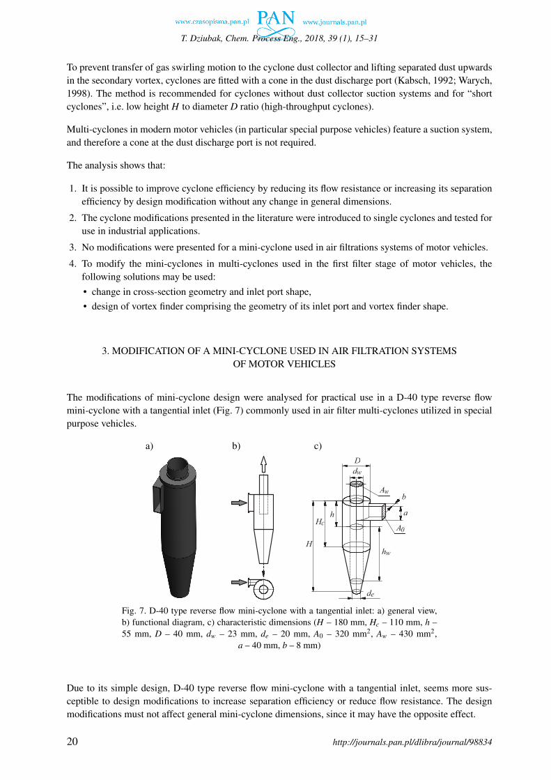
The modifications of mini-cyclone design were analysed for practical use in a D-40 type reverse flowmini-cyclone with a tangential inlet (Fig. 7) commonly used in air filter multi-cyclones utilized in specialpurpose vehicles.
a) b) c)
h
b
a
A
h
H
w
de
0
A
dw
w
D
c
H
Fig. 7. D-40 type reverse flow mini-cyclone with a tangential inlet: a) general view,b) functional diagram, c) characteristic dimensions (H – 180 mm, Hc – 110 mm, h –55 mm, D – 40 mm, dw – 23 mm, de – 20 mm, A0 – 320 mm2, Aw – 430 mm2,
a – 40 mm, b – 8 mm)
Due to its simple design, D-40 type reverse flow mini-cyclone with a tangential inlet, seems more sus-ceptible to design modifications to increase separation efficiency or reduce flow resistance. The designmodifications must not affect general mini-cyclone dimensions, since it may have the opposite effect.
http://journals.pan.pl/dlibra/journal/9883420

Potential design improvements of a reverse flow mini-cyclone with a tangential inlet
D-40 mini-cyclone design was modified as follows:
• asymmetric curvilinear shape of the outlet port instead of symmetrical shape (Fig. 8),
• streamlined outlet vortex finder’s inlet port (Fig. 9),
• conical outlet vortex finder dw (Fig. 10).
a) b)
h
A
h
dw dw
Fig. 8. Modified D-40 type mini-cyclone design: a) original (symmetrical)inlet port, b) asymmetrical curvilinear inlet
a) b)
h
dw
zBhg
R
"B"
dw
Fig. 9. type mini-cyclone: a) cylindrical outlet vortex finder – original version, b) cylindricaloutlet vortex finder with streamlined inlet port
The existing cylindrical outlet vortex finder with internal diameter dw was replaced with a truncated cone-shaped vortex finder, with a smaller diameter equal to the inner diameter of the outlet vortex finder dw =
23 mm. A conical outlet vortex finder is a diffuser with an angle of flare αs = 7◦C. For the angle value,the stream does not separate from the wall, no vortices are formed, and according to research (Bukowski,1968) the coefficient of flow resistance ξ reaches the minimum.
http://journals.pan.pl/dlibra/journal/98834 21

T. Dziubak, Chem. Process Eng., 2018, 39 (1), 15–31
h
dw
h
α
C z
wd
g
R
"C"
1
wd
s
a) b)
Fig. 10. D-40 type mini-cyclone: a) cylindrical outlet vortex finder – original version, b) conicaloutlet vortex finder with streamlined inlet port
4. TEST METHODS AND CONDITIONS
Mini-cyclone tests were performed on a special test stand (Fig. 11) for testing characteristics of separationefficiency φc = f (QG), flow resistance ∆pc = f (QGc) for air flow rate < 85 m3/h (0.0305 kg/s) at ejectorsuction rate < 20% and dust concentration < 3 g/m3.
a
e
m
S GQ
M
m
Q - test air stream
- shielding air stream
13
dQ0
15
7
6
12
11 10
14
5
3
4
2
b
c
8 9
1
dusted air
clean air (downstream of the cyclone)
Air strem
fed dustair discharged with air
T p w
16QB
AG
D
Q
EQ
HH H
∆hw
B
EQ
Fig. 11. Mini-cyclone test stand diagram: 1 – mini-cyclone, 2 – dust collector, 3 – dust chamber, 4 – dust feeder,5 – absolute rated filter, dust suction line, 6 – mini-cyclone flow resistance measuring line, 7 – CL1A pressuresensor, 8 – pressure transducer and CL 134/24V control panel, 9 – measuring line with particle counter probe(a – sensor, b – filter air, c – block of the flow control, d – pump, e – computer), 10 – measuring probe, 11 – particlecounter, 12 – absolute rated filter, main line, 13, 14 – main and suction stream measuring rotameters, 15 – suction
fan, 16 – pressure, temperature and relative humidity measuring unit
The test stand included a particle counter Pamas-2132 with sensor HCB-LD-2A-2000-1 to determinenumber and size of dust particles in the air stream downstream of the mini-cyclone ranging from 0.7 to100 µm, in i = 32 ranges limited with diameters (dzimin − dzimax). The range widths of measured size
http://journals.pan.pl/dlibra/journal/9883422

Potential design improvements of a reverse flow mini-cyclone with a tangential inlet
distribution are freely programmable. The maximum particle count for precise measurement (to avoidcoincidence) is limited to 1000/ml, corresponding to a mass dust concentration s ≈ 0.25 g/m3.
Downstream the test equipment the purified air stream passes through an absolute filter, which protectsthe rotameter against dust ingress, and at the same time it enables to determine collected dust mass mAG
penetrating through the mini-cyclone and as a result determine mini-cyclone separation efficiency φc.Mini-cyclone tests were performed for the air stream QGmin −QGmax resulting from the number of mini-cyclones used in T-72 tank air filter’s multi-cyclone and air demand ranging from QGc =1200–3400 m3/h(0.42–1.21 kg/s) in the tank engine speed range nmin −nN .
The duration of a single measurement (time of uniform feeding and distribution of test dust at dust con-centration s = 1 g/m3) was texp = 3 min. PTC-D test dust, a substitute for AC-fine test dust was used. Sizedistribution and chemical composition of the PTC-D dust is presented in Fig. 12.
a) b)
Fig. 12. PTC-D test dust used for testing: a) size distribution, b) chemical composition (PN-S- 34040, 1996)
The separation efficiency φc of the mini-cyclone was determined using a gravimetric method for prede-fined air flow rate QGc = 6–34 m3/h (every 4 m3/h) and corresponding flow rate of air discharged throughthe bottom with dust particles QS was 8% of the total outlet flow QGc.
A number of j =5 measurements was performed for each measuring point p = I, II, III ... k, starting atQGc = 6 m3/h, and separation efficiency φc j of the mini-cyclone was calculated for each measurementfrom the following relation:
φc j =mZc j
mDc j·100% (2)
Mass of dust fed to the cyclone was determined after each measurement from the following relation:
mDc j = m′Dc j −m′′
Dc j (3)
Mass of dust retained by the mini-cyclone was determined after each measurement from the followingrelation:
mZc j = mDc j −mAG j (4)
Mass mAG j of dust retained by absolute rated filter on the main line determined from the following relation:
mAG j = m′′AG j −m′
AG j (5)
http://journals.pan.pl/dlibra/journal/98834 23

T. Dziubak, Chem. Process Eng., 2018, 39 (1), 15–31
In the distance 6dw from the face surface of the mini-cyclone body (where dw internal diameter of themini-cyclone outlet line) the static pressure drop ∆hw j in mm H2O was read out on the pressure transducerpanel, and the value of mini-cyclone flow resistance ∆pc was determined from the following relation:
∆pc j =∆hw j
1000(ρm −ρH)g (6)
The air dust concentration in time for all measurements was calculated from the following relation:
s j =mDc j
Q0c j · texp=
mDc j
(QGc j +QSc j) · texp(7)
After the cycle of j = 5 measurements in a point p, the mean values of separation efficiency, flow resistanceand dust concentration were calculated.
During the measurement (tp = 1/2 texp time), the number and size of dust particles in air downstreamof the mini-cyclone was determined using a particle counter. The Upi fraction of dust particles for eachmeasuring range (dzimin − dzimax) in the total number of dust particles for all measuring ranges i wascalculated:
U pi =Ni
32
∑i=1
Ni
(8)
The experimental tests also included determination of characteristics of separation efficiency φc = f (QGc)
and flow resistance ∆pc = f (QGc) and separation performance (measurement of number and size of dustparticles in the air stream QGc) of D-40 type mini-cyclone: in original version – stage I and modifiedversion – stage II.
5. TEST RESULT ANALYSIS
The characteristics of separation efficiency φc = f (QGc) (Fig. 13a) of D-40 type mini-cyclone in originalversion have a similar course and conform to the information presented by the authors of many researchstudies and other authors’ research studies (Dziubak 2000, Dziubak 2004, Dziubak 2006). With the in-crease in air stream value QGc = 6−18 m3/h (corresponding to the average flow velocity at the outletυw = 4−12 m/s), the separation efficiency φc of the tested mini-cyclone increases rapidly.
Mini-cyclone flow velocity (average) outlet υw was determined from the following relation:
υw =QGc
3600 ·Aw[m/s] (9)
Further increase of air stream QGc results in a slight increase in separation efficiency φc, whereas a slightdecrease is observed in the final mini-cyclone operation phase. Maximum mini-cyclone separation effi-ciency φcmax ∼=96.2% is achieved for the air stream value QGc = 22−26 m3/h. The course of separationefficiency φc = f (QGc) change is mainly caused by the interrelations between inertia forces Pd actingon a dust particle and aerodynamic forces PR of the gas stream. With the increase in air stream flowingthrough the mini-cyclone (flow rate) the values of both forces increase, whereas at higher air stream values(above QGc = 18 m3/h for the tested mini-cyclone) the increase in aerodynamic force PR is higher thanthe increase in inertia force Pd , which impedes particle movement and may result in secondary capture bythe outlet air stream from the mini-cyclone. The mini-cyclone separation efficiency is reduced as a result.
http://journals.pan.pl/dlibra/journal/9883424

Potential design improvements of a reverse flow mini-cyclone with a tangential inlet
Fig. 13b shows a relation between the separation efficiency φc and the dust particle size dzmax in theair downstream of D-40 type mini-cyclone in its original version. The increase in air stream (flow rate)QGc = 6−22 m3/h results in dust particles with continuously decreasing dimensions downstream of themini-cyclone, which explains the increase in mini-cyclone separation efficiency φc within this range.
a) b)
Fig. 13. D-40 type mini-cyclone characteristics – original version: a) separation efficiency φc = f (QGc)and flow resistance ∆pc = f (QGc), b) dust particle sizes dzmax = f (QGc)
For air stream QGc = 6 m3/h, the values of maximum dust particle sizes dzmax are the highest withinthe range of dzmax = 27.1−28.7 µm, and for QGc = 22 m3/h the values are the lowest within the rangeof dzmax = 13.5−15.1 µm. With the further increase in flow rate in the mini-cyclone, the effect of anincrease in maximum dust particle size dzmax is observed in the outlet air stream with a slight decreasein separation efficiency φc. Air particles with a maximum size of dzmax = 23.9 µm are present in the airstream at QGc = 34 m3/h.
Irrespective of the stream QGc value, the number of dust particles in the air downstream of the mini-cyclone (with the increase in size) is reduced until total elimination. The dust particle fraction Up fromeach measuring range ∆dz decreases continuously – Fig. 14. In the last measuring range, a single dustparticle is usually present (dz = dzmax size). Similar test results were obtained by Jo et al., (2000), testinga reverse flow mini-cyclone with a tangential inlet with D = 31.1 mm diameter at air stream QGc =
30.24−66.24 m3/h with test dust density of ρzp = 0.98 g/cm3.
Large dust particles in the air downstream of the mini-cyclone at higher air stream values may be causedby the dust particles hitting a mini-cyclone wall at high speed bouncing from the wall, captured by theair stream and discharged to the mini-cyclone outlet (Dzierzanowski et al., 1985; Szczecinski, 2009).Those are single particles with large size and weight. The dust particle with the largest size dz = dzmax inthe air downstream of the mini-cyclone is taken as an assessment criteria for mini-cyclone air separationefficiency.
http://journals.pan.pl/dlibra/journal/98834 25

T. Dziubak, Chem. Process Eng., 2018, 39 (1), 15–31
Fig. 14. Fraction of dust particles in the air downstream of D-40 type mini-cyclonefor various air stream QGc values
Theoretically, in the air downstream of the mini-cyclone at steady flow conditions (constant QGc streamvalue), only dust particles below a specific limiting size dzg, should be present, with a value determinedfrom the relation specified by Dziubak (2012) and modified by the author:
dzg =32
√A0
Aw
Dυ0
(Ddw
)−(2m+1)(hw
dw
)−1 µg
ρzp(10)
Mini-cyclone inlet flow velocity (average) υ0 was determined from the following relation:
υ0 =Q0
3600 ·A0[m/s] (11)
Table 1 shows the maximum size of particles dzgr as calculated from Equation (6) of main dust components(SiO2, Al2O3, Fe2O3) for the tested mini-cyclone.
Table 1. Dust particle boundary size dzgr calculation results
QGc υ0dzgr [µm]
[m3/h] [m/s] SiO2 Al2O3 Fe2O3
ρzp = 2.65 g/cm3 ρzp = 3.99 g/cm3 ρzp = 5.24 g/cm3
6 5.65 2.23 1.85 1.59
22 20.6 1.16 0.96 0.84
34 31.8 0.94 0.79 0.68
Calculated dzgr sizes differ from one another and have very low values (2.23–0.68 µm), significantly lowerthan the dust particle sizes dzmax present in the air downstream of the tested mini-cyclone. With the increasein air stream QGc flowing through the mini-cyclone and dust particle density, sizes dzgr continuouslydecrease, corresponding to the general theory of mini-cyclone operation.
http://journals.pan.pl/dlibra/journal/9883426
Potential design improvements of a reverse flow mini-cyclone with a tangential inlet
There is no visible boundary (boundary particle size dzgr), above which all dust particles will be retained bythe mini-cyclone. The PTC-D test dust used for tests, corresponding to the road dust is a polydispersed dustwith variable chemical composition. Dust particles are characterized by a different size (up to dz = 80 µm),variable shape (other than spherical) and density (Table 1). The dust particles of the same size (and thesame volume) have various weight affecting inertia force. An adverse PR and Pd force relation includeslow weight and high volume (low density) dust particles. Assuming lack of the effect of particle shape onmedium resisting force PR the particles with higher density, e.g. iron oxides or corundum will be separatedwith higher efficiency.
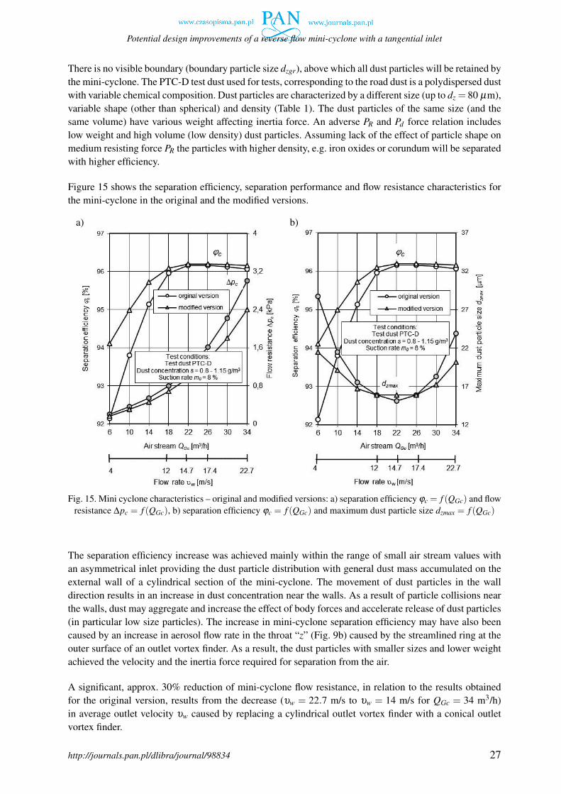
Figure 15 shows the separation efficiency, separation performance and flow resistance characteristics forthe mini-cyclone in the original and the modified versions.
a) b)
Fig. 15. Mini cyclone characteristics – original and modified versions: a) separation efficiency φc = f (QGc) and flowresistance ∆pc = f (QGc), b) separation efficiency φc = f (QGc) and maximum dust particle size dzmax = f (QGc)
The separation efficiency increase was achieved mainly within the range of small air stream values withan asymmetrical inlet providing the dust particle distribution with general dust mass accumulated on theexternal wall of a cylindrical section of the mini-cyclone. The movement of dust particles in the walldirection results in an increase in dust concentration near the walls. As a result of particle collisions nearthe walls, dust may aggregate and increase the effect of body forces and accelerate release of dust particles(in particular low size particles). The increase in mini-cyclone separation efficiency may have also beencaused by an increase in aerosol flow rate in the throat “z” (Fig. 9b) caused by the streamlined ring at theouter surface of an outlet vortex finder. As a result, the dust particles with smaller sizes and lower weightachieved the velocity and the inertia force required for separation from the air.
A significant, approx. 30% reduction of mini-cyclone flow resistance, in relation to the results obtainedfor the original version, results from the decrease (υw = 22.7 m/s to υw = 14 m/s for QGc = 34 m3/h)in average outlet velocity υw caused by replacing a cylindrical outlet vortex finder with a conical outletvortex finder.
http://journals.pan.pl/dlibra/journal/98834 27

T. Dziubak, Chem. Process Eng., 2018, 39 (1), 15–31
The modification resulted in the increase in mini-cyclone separation efficiency, observed as a reduction inmaximum dust particle size dzmax fraction in the air downstream of the mini-cyclone within minimum andmaximum values of the air stream QGc flowing through the mini-cyclone.
Based on data presented in Figs. 13 to 15, the D-40 type mini-cyclone should operate within a wide rangeof air stream fluctuations QGc = 18−26 m3/h resulting from the maximum separation performance andminimum size dust particle concentration. A wider range would bring about a decrease of mini-cycloneefficiency and reduced separation performance, which would lead to a mass of dust being retained at thesecond filtration stage, and thus accelerated increase in flow resistance.
6. CONCLUSIONS
• Although there are several modifications available to improve a cyclone performance, not all solutionsmay be used in mini-cyclones utilized in the inlet air filtration systems of motor vehicles due to theircomplex design. An improved separation efficiency or a reduced flow resistance may be dispropor-tionately low compared to the modification costs.
• For modification of mini-cyclones used in multi-cyclones of motor vehicle air filters, the follow-ing solutions may be used: modification of inlet port shape – replacing a symmetrical inlet with anasymmetrical inlet, modification of outlet duct (outlet vortex finder) shape from cylindrical to conical,streamlined outlet duct’s inlet port shape or using cone in a dust discharge port.
• The separation efficiency of tested mini-cyclones (reverse flow cyclone with a tangential inlet in re-lation to a polydisperse dust with particle size up to dz increases with the increase in flow rate υ (airstream QGc) up to φcmax ≈ 96.2%, and is slightly reduced with further flow rate increase – Fig. 13.The course characteristics φc = f (υ) and efficiency values correspond to the data available in the lit-erature presented by the authors of research studies (Hoffmann et al., 1991; Juda, 1968; Kabsch, 1992;Warych, 1998), and other author’s research results (Dziubak, 2010, Dziubak, 1995).
• For specific flow conditions (QGc), the number of dust particles in the air downstream of the mini-cyclone is systematically reduced with the increase in size and continues until total elimination –Fig. 14. In the last measuring range, a single dust particle is usually present (dz = dzmax maximumsize). There is no visible difference (at the boundary particle size dzgr) between the dust particlesretained by the mini-cyclone and discharged from the mini-cyclone with air. It is caused by the dustpolydispersity, chemical properties and particle shape.
• For the air stream corresponding to the maximum separation efficiency φcmax, the maximum size ofthe dust particles in the air downstream the mini-cyclone (not separated in the mini-cyclone) achievesthe lowest values within the range of dzmax = 13.5−15.1 µm – Fig. 15, indicating an optimum rangeof the average outlet velocity υw for the mini-cyclone.
• The modified mini-cyclone design does not significantly affect changes in φc and ∆pc characteristics.The effect of design modification is a significant 30% reduction of flow resistance within the entirerange of air stream QGc and approx. 2% increase in separation performance φc within the range ofthe lowest air stream QGc values and significant reduction of maximum dust particle dzmax at extreme(QGc = 6 m3/h and QGc = 34 m3/h) air stream values – Fig. 15.
SYMBOLS
A cross-section area, m2
D cyclone diameter, m
http://journals.pan.pl/dlibra/journal/9883428

Potential design improvements of a reverse flow mini-cyclone with a tangential inlet
dw outlet vortex finder diameter, mH cyclone height, mhw outlet height, mm equation exponent, 0.5–0.9mZc mass of dust retained by mini-cyclone, kgmDc mass of dust fed to cyclone in time texp, kgmAG mass of dust retained by absolute rated filter on the main line determined, kgm′
AG j weight of absolute rated filter element before the measurement, kgm′′
AG j weight of absolute rated filter element after the measurement, kgm′
Dc j dust feeder container weight before the measurement, kgm′′
Dc j dust feeder container weight after the measurement, kgs dust concentration, g/m3
texp time of uniform dust mass mD j feeding to the inlet air stream of the mini-cyclone Q0c, sQ volumetric flow rate, m3/s
Greek symbols
∆pc air flow resistance upstream of mini-cyclone, Paµg dynamic gas viscosity, kg/m sρa air density, kg/m3
ρzp dust particle density, g/cm3
ξ the coefficient of flow resistanceυw minicyclone outlet velocity, m/sυ0 minicyclone inlet velocity, m/s
Subscripts
a airc cycloneD intakeG mainH environmental conditionsi, j range, measuring cyclek contractionm manometric liquidN the number of grainsp measuring pointR aerodynamic forcesS, s ejecting suction, conew inletZ dust retained0 average value
REFERENCES
Azadi M., Azadi M., 2012. An analytical study of the effect of inlet velocity on the cyclone performance usingmathematical models. Powder Technol., 217, 121–127. DOI: 10.1016/j.powtec.2011.10.017.
Baczewski K., Hebda M., 1991/92. Filtracja płynów eksploatacyjnych. Radom, MCNEMT (in Polish).
Bernardo S., Mori M., Peres A.P., Dionısio R.P., 2006. 3-D computational fluid dynamics for gas and gas-particleflows in a cyclone with different inlet section angles. Powder Technol., 162, 190–200. DOI: 10.1016/j.powtec.2005.11.007.
http://journals.pan.pl/dlibra/journal/98834 29

T. Dziubak, Chem. Process Eng., 2018, 39 (1), 15–31
Bukowski J., 1968. Mechanika płynów. Warszawa, PWN (in Polish).
Cenrtisep Air Cleaner. 2004. PALL Corporation, USA.
Chu K.W., Wang B., Xu D.L., Chen Y.X., Yu A.B., 2011. CFD–DEM simulation of the gas–solid flow in a cycloneseparator. Chem. Eng. Sci., 66, 834–847. DOI: 10.1016/j.ces.2010.11.026.
Cortés C., Gil A., 2007. Modeling the gas and particle flow inside cyclone separators. Prog. Energy Combust. Sci.,33, 409–452. DOI: 10.1016/j.pecs.2007.02.001.
Durst M., Klein G., Moser N., 2005. Filtration in Fahrzeugen. Ludwigsburg, Deutschland.
Dzierzanowski P., Kordzinski W., Otys J., Szczecinski S., Wiatrek R., 1985. Napedy lotnicze. Turbinowe silnikismigłowe i smigłowcowe. Warszawa, Wydawnictwa Komunikacji i Łacznosci (in Polish).
Dziubak T., 2012. The assessment of the possibilities of improvement of the extraction evenness in multicyclonededusters fitted in special vehicles. Combustion Engines, 4, 151, 34–42.
Dziubak T., 2009. The problems of the inlet air filtration in the special vehicles combustion engines. III Interna-tional Congress on Combustion Engines, Opole 22-24.06.2009. Combustion Engines, 2009-SC1, 115–123.
Dziubak T., 2006. Modification of returnable cyclone with a tangent inlet construction. Bulletin of the MilitaryUniversity of Technology, LV, 2, 279–301.
Dziubak T., 2004. The experimental assessment of constructional changes of motor vehicle air filter. Bulletin ofthe Military University of Technology, LIII, 10, 121–138.
Dziubak T., 2000. The problems of the air filtration in the vehicle engines exploitated in large pollution conditions.Zagadnienia Eksploatacji Maszyn, 35 (4), 181–197 (in Polish).
Dziubak T., 1995. Experimental investigation of returnable minicyclone with tangential inlet. Bulletin of the Mili-tary University of Technology, XLIV, 3/4, 113–125.
Hoffmann A.C., Arends H., Sie H., 1991. An experimental investigation elucidating the nature of the effect ofsolids loading on cyclone performance. Filtr. Sep., 28, 188-193. DOI: 10.1016/0015-1882(91)80074-F.
Honeywell International Inc., 2000. AGT1500 Turbine Technology, Honeywell International Inc., USA. Availableat: www.honeywell.com.
Jiao J., Zheng Y., Sun G., Wang J., 2006. Study of the separation efficiency and the flow field of a dynamic cyclone.Sep. Purif. Technol., 49, 157–166. DOI: 10.1016/j.seppur.2005.09.011.
Jo Y., Tien Ch., Ray M.B., 2000. Development of a post cyclone to improve the efficiency of reverse flow cyclones.Powder Technol., 113, 97-108. DOI: 10.1016/S0032-5910(00)00206-0.
Juda J., 1968. Pomiary zapylenia i technika odpylania. Warszawa, WNT (in Polish).
Jung Ch.H., Xiang R.B., Kim M.C., Lim K.S., Lee K.W., 2004. Performance evaluation of a cyclone with granularpacked beds. J. Aerosol Sci., 35, 1483–1496. DOI: 10.1016/j.jaerosci.2004.06.076.
Kabsch P., 1992. Odpylanie i odpylacze. Warszawa, WNT (in Polish).
Karagoz I., Avci A., Surmen A., Sendogan O., 2013. Design and performance valuation of a new cyclone separator.J. Aerosol Sci., 59, 57–64. DOI: 10.1016/j.jaerosci.2013.01.010.
Kobyłecki R., 2011. Unburned carbon in the circulating fluidised bed boiler fly ash. Chem. Process Eng., 32,255–266. DOI: 10.2478/v10176-011-0020-8.
Krasinski A., 2007. Estimation of operation parameters of cyclones based on the CFD simulations. Chem. ProcessEng., 28, 4, 961–972.
Lim K.S., Kim H.S., Lee K.W., 2004. Characteristics of the collection efficiency for a cyclone with different tubeshapes. J. Aerosol Sci., 35, 743–754. DOI: 10.1016/j.jaerosci.2003.12.002.
Lim K.S., Kwon S.B., Lee K.W., 2003 Characteristics of the collection efficiency for a double cyclone with cleanair inlet. J. Aerosol Sci., 34, 1085–1095. DOI: 10.1016/S0021-8502(03)00079-X.
Liu Z., Zheng Y., Jia L., Jiao J., Zhang O., 2006. Stereoscopic PIV studies on the swirling flow structure in a gascyclone. Chem. Eng. Sci., 61, 4252–4261. DOI: 10.1016/j.ces.2006.01.024.
http://journals.pan.pl/dlibra/journal/9883430
Potential design improvements of a reverse flow mini-cyclone with a tangential inlet
Ma L., Ingham D.B., Wen X,. 2000. Numerical modelling of the fluid and particle penetration through smallsampling cyclones. J. Aerosol Sci., 31, 1097–1119. DOI: 10.1016/S0021-8502(00)00016-1.
PN-S-34040, Silniki spalinowe. Filtry powietrza. Wymagania i badania. PKN, 1996.
Sakura G.B., Leung A.Y.T., 2015. CFD simulation of cyclone separators to reduce air pollution. Powder Technol.,286, 488–506. DOI: 10.1016/j.powtec.2015.08.023.
Swift P., 1986. An empirical approach to cyclone design and application. Filtr. Sep., 23, 1, 24–27.
Szczecinski S., 2009. The problems of filtration of inlet air for turbine helicopter engines. Trans. Aviation Institute,199, 25–30.
Wang B., Xu D.L., Chu K.W., Yu A.B., 2006. Numerical study of gas–solid flow in a cyclone separator. Appl.Math. Modell., 30, 1326–1342. DOI: 10.1016/j.apm.2006.03.011.
Wasilewski M., Duda J., 2016. Multicriteria optimisation of first-stage cyclones in the clinker burning systemby means of numerical modelling and experimental research. Powder Technol., 289, 143–158. DOI: 10.1016/j.powtec. 2015.11.018.
Warych J., 1998. Oczyszczanie gazów – procesy i aparatura. Warszawa, WNT (in Polish).
Winfield D., Cross M., Croft N., Paddison D., Craig I., 2013. Performance comparison of a single and tripletangential inlet gas separation cyclone: A CFD study. Powder Technol., 235, 520–531. DOI: 10.1016/j.powtec.2012.10.026.
Qian F., Zhang J., Zhang M., 2006. Effects of the prolonged vertical tube on the separation performance of a cy-clone. J. Hazard. Mater., 136, 822–829. DOI: 10.1016/j.jhazmat.2006.01.028
Yoshida H., Ono K., Fukui K., 2005. The effect of a new method of fluid flow control on submicron particleclassification in gas-cyclones. Powder Technol., 149, 139–147. DOI: 10.1016/j.powtec.2004.10.005
Zhao B., Shen H., Kang Y., 2004. Development of a symmetrical spiral inlet to improve cyclone separator perfor-mance. Powder Technol., 145, 47–50. DOI: 10.1016/j.powtec.2004.06.001.
Zhu Y., Kim M.C., Lee K.W., Park Y.O., Kuhlman M.R., 2001. Design and performance evaluation of a noveldouble cyclone. Aerosol Sci. Technol., 34, 373–380. DOI: 10.1080/02786820120723.
Received 27 July 2017Received in revised form 11 December 2017Accepted 14 December 2017
http://journals.pan.pl/dlibra/journal/98834 31