Embed Size (px)
Citation preview
Otowave 102-1 & 102-4 Operating Manual
ABOUT THIS MANUAL READ THIS OPERATING MANUAL BEFORE ATTEMPTING TO USE THE INSTRUMENT.
This manual is valid for the Otowave 102-1 & 102-4 (applies from firmware version 1.0.0.072100 onwards – see System Information screen).
This product is manufactured by:
Amplivox Ltd.
3800 Parkside, Solihull Parkway, Birmingham Business Park,
Birmingham, West Midlands, B37 7YG
United Kingdom www.amplivox.com
For all enquiries please contact us under: Amplivox Ltd.
10393 West 70th Street Eden Prairie
MN 55344 United States
Tel: 888 941 4208 Fax: 952 903 4100 [email protected]
Amplivox Ltd. 3800 Parkside, Solihull Parkway,
Birmingham Business Park, Birmingham, West Midlands,
B37 7YG United Kingdom
Tel: +44 (0)1865 880846

For supply in US only
Caution: Federal Law restricts this device to sale by or on the order of a licenced medical professional.
i D-0115690-H (OM001) – Otowave 102 Operating Manual
TABLE OF CONTENTS
1. Introduction .......................................................................................................................................................... 1
1.1. Thank you ..................................................................................................................................................................... 1 1.2. Intended applications ................................................................................................................................................... 1 1.3. Features ........................................................................................................................................................................ 1 1.4. Unpacking ..................................................................................................................................................................... 1 1.5. Standard contents and optional accessories ................................................................................................................ 2 1.6. Guarantee ..................................................................................................................................................................... 2 1.7. Warnings ....................................................................................................................................................................... 2
2. Important Safety Instructions ............................................................................................................................... 3
2.1. Precautions ................................................................................................................................................................... 3 2.2. Electromagnetic compatibility (EMC) considerations .................................................................................................. 3
3. Principles of Operation ......................................................................................................................................... 4
3.1. Compliance measurement............................................................................................................................................ 4 3.2. Tympanogram ............................................................................................................................................................... 4 3.3. Stapedial reflex measurement ..................................................................................................................................... 4
4. Using the Otowave................................................................................................................................................ 5
4.1. Installing & replacing batteries ..................................................................................................................................... 5 4.2. Operating language ...................................................................................................................................................... 5 4.3. Controls and indicators ................................................................................................................................................. 5 4.4. The probe ..................................................................................................................................................................... 6 4.5. Start-up and menu displays .......................................................................................................................................... 7 4.6. Initial settings ............................................................................................................................................................... 7
5. Taking measurements ........................................................................................................................................... 8
5.1. Prior to testing and Ambient conditions ...................................................................................................................... 8 5.2. Ear tip(s) ........................................................................................................................................................................ 8 5.3. Performing a test .......................................................................................................................................................... 8 5.4. Ear seal check ............................................................................................................................................................. 12 5.5. Error messages ........................................................................................................................................................... 13
6. Configuration ...................................................................................................................................................... 14
6.1. Sweep Settings ........................................................................................................................................................... 14 6.2. Reflex options ............................................................................................................................................................. 14 6.3. System Settings........................................................................................................................................................... 16
7. Saving Results in the Internal Database .............................................................................................................. 17
7.1. General ....................................................................................................................................................................... 17 7.2. Data entry ................................................................................................................................................................... 17 7.3. Database full ............................................................................................................................................................... 17
8. IrDA Communications ......................................................................................................................................... 18
9. Transferring the Results ...................................................................................................................................... 19
9.1. Sending the results to a printer .................................................................................................................................. 19 9.2. Data transfer to NOAH or ampliSuite ......................................................................................................................... 19
10. Data Management .............................................................................................................................................. 20
10.1. List records ................................................................................................................................................................. 20 10.2. Delete records ............................................................................................................................................................ 21 10.3. Print records ............................................................................................................................................................... 21 10.4. Send records to a computer ....................................................................................................................................... 21
ii D-0115690-I (OM001) – Otowave 102 Operating Manual
11. Performing Daily Checks ..................................................................................................................................... 22
12. System Information ............................................................................................................................................ 23
13. Routine Maintenance ......................................................................................................................................... 24
13.1. Cleaning the Otowave ................................................................................................................................................ 24 13.2. Ear tip and Probe ........................................................................................................................................................ 24 13.3. Calibration and Repair of the Instrument ................................................................................................................... 24
14. Error Messages & Fault Conditions ..................................................................................................................... 25
15. Technical Specification ........................................................................................................................................ 27
15.1. Performance ............................................................................................................................................................... 27 15.2. Equipment classification ............................................................................................................................................. 28 15.3. Symbols....................................................................................................................................................................... 29
16. Ordering Consumables and Accessories .............................................................................................................. 30
17. Disposal Information ........................................................................................................................................... 31
18. EMC Guidance & Manufacturer’s Declaration ..................................................................................................... 32
19. Use with Non-medical Electrical Equipment ........................................................................................................ 36
INTRODUCTION
1 D-0115690-I (OM001) – Otowave 102 Operating Manual
1. INTRODUCTION
1.1. THANK YOU
Thank you for purchasing an Amplivox Otowave 102, a hand-held, portable tympanometer that will give many years of reliable service if treated with care. This operating manual covers product variants 102-1 & 102-4.
1.2. INTENDED APPLICATIONS
The Otowave 102 is designed for use by audiologists, general practitioners, hearing aid dispensers and child health professionals.
The instrument performs two types of measurement:
Tympanometry is used to measure the compliance of the tympanic membrane and middle ear at a fixed frequency over a range of pressures.
Reflex tests are used to measure stapedial reflexes. The Otowave measures ipsilateral reflexes and, when selected, reflex measurement is automatically carried out after a tympanogram is taken.
1.3. FEATURES
• Automatic measurement of ear canal volume, tympanic compliance peak, placement of the peak and the gradient
• Automatic detection of stapedial reflexes
• Up to 32, dual-ear patient tests can be stored in non-volatile memory
• Configurable settings for user preferences, held in non-volatile memory
• Printout via an infrared (IrDA) link to one of two thermal printers that may be selected by the user
• Data transfer to a computer via an infrared IrDA link for storage viewing & printing using either the Amplivox “ampliSuite” software or the NOAH application
• English, French, Spanish, Portugese, Italian or German operating languages (user-selectable)
1.4. UNPACKING
Please check the contents of the shipping carton against the delivery note to make sure that all items ordered have been included. If anything is missing, please contact the distributor who supplied your instrument or Amplivox if you purchased direct.
Please retain the original shipping carton and packaging to transport the tympanometer for annual calibration or repair.

INTRODUCTION
2 D-0115690-I (OM001) – Otowave 102 Operating Manual
1.5. STANDARD CONTENTS AND OPTIONAL ACCESSORIES
STANDARD COMPONENTS
Otowave 102 Tympanometer 8000402 Set of disposable ear-tips 8029344 USB stick with Software (ampliSuite and Noah impedance module) and Operating Manuals
8517685 4 in 1 cavity assembly (0.2 ml/0.5 ml/2.0 ml/5.0 ml)
8011362
4 x 1.5 V ‘AA’ Batteries 8011226 Carrying case 8004651 Calibration certificate
OPTIONAL COMPONENTS
Additional sets of ear tips Probe tip 80025921
Portable thermal printer (standard in US conf.)
8503007 Seal (in probe tip) 80020091
Additional rolls of thermal printer paper (standard in US conf.)
8029305 Infra-red USB Adapter 8105188
Please note: If the thermal printer has been purchased it should be charged for a minimum of 15 hours before being used. Refer to the printer instructions for further details.
1.6. GUARANTEE
All Amplivox instruments are guaranteed against faulty materials and manufacture. The instrument will be repaired free of charge for a period of three years from the date of dispatch if returned, carriage paid, to the Amplivox service department. Return carriage is free of charge for customers in the UK and chargeable for overseas customers.
The following exceptions apply:
• The pressure pump and transducers may go out of calibration due to rough handling or impact (dropping)
The lifetime of probe, probe seals and ear tips is dependent upon conditions of use. These parts are only guaranteed against faulty materials or manufacture.
1.7. WARNINGS
Throughout this manual, the following meanings of warnings and cautions apply:
The WARNING label identifies conditions or practices that may present danger to the patient and/or user.
The CAUTION label identifies conditions or practices that could result in damage to the equipment.
1 Applied part as according to IEC 60601-1
WARNING
WARNING
CAUTION
IMPORTANT SAFETY INSTRUCTIONS
3 D-0115690-I (OM001) – Otowave 102 Operating Manual
2. IMPORTANT SAFETY INSTRUCTIONS
The Otowave 102 instrument must be used only by practitioners qualified to perform tympanometric tests. It is intended for transient use as a screening and diagnostic tool; however no surgical or medical procedure should be undertaken solely on the basis of results obtained from the instrument.
2.1. PRECAUTIONS
READ THIS OPERATING MANUAL BEFORE ATTEMPTING TO USE THE INSTRUMENT
The tympanometer is for indoor use only and should be used only as described in this manual.
Refer to the precautions specified in Section 4.1 regarding the use of batteries.
Before the first use of the instrument each day, or if suspect or inconsistent results are apparent, the checks specified in Section 11 must be carried out. If these do not give the results specified, the instrument must not be used.
Never insert the probe into a patient’s ear canal without a suitable ear tip fitted to the probe.
Use only the recommended disposable ear tips . These are for single use only - that is, each ear tip is intended to be used once only for a single ear for a single patient. Do not reuse ear tips as this will pose the risk of ear-to-ear or patient-to-patient cross-infection.
Do not immerse the unit in any fluids. See Section 13 of this manual for the proper cleaning procedure for the instrument and its accessories and the function of single-use parts.
Do not use the instrument in an oxygen-rich environment or in the presence of a flammable anaesthetic mixture or other flammable agents.
Do not drop or otherwise impact this instrument. If the instrument is dropped or damaged, return it to the manufacturer for repair and/or calibration. Do not use the instrument if any damage is suspected.
The instrument must be stored and used indoors within the specified temperature, pressure and humidity ranges, see Section 15.
As with all instruments of this nature the measurements taken will be influenced by significant changes in altitude & pressure. The Otowave 102 tympanometer must be re-calibrated (for volume measurement only) at the intended operating elevation if it is to be used at elevations greater than 1000m above mean sea level. This applies to volume measurements up to 2.0ml maximum. Please refer to the service manual for more information.
Do not attempt to open, modify or service the instrument. Return the instrument to the manufacturer or distributor for all repair and servicing requirements. Opening the instrument will void the warranty.
2.2. ELECTROMAGNETIC COMPATIBILITY (EMC) CONSIDERATIONS
Medical electrical equipment needs special precautions regarding EMC and needs to be installed and put into service according to the EMC information in Section 18. This provides guidance on the electromagnetic environment in which to operate the instrument.
Portable and mobile radio-frequency (RF) communications equipment can affect medical electrical equipment. The instrument should not be used adjacent to or stacked with other equipment; if this is unavoidable the instrument should be observed to verify normal operation.
WARNING
PRINCIPLES OF OPERATION
4 D-0115690-I (OM001) – Otowave 102 Operating Manual
3. PRINCIPLES OF OPERATION Please note: This operating manual is not intended as a training manual for tympanometry. The reader should consult standard audiology texts for the theory and application of the screening tests provided by this instrument.
3.1. COMPLIANCE MEASUREMENT
The Otowave 102 measures the compliance of the tympanic membrane and middle ear by playing a continuous 226Hz tone into the ear canal at a level calibrated to give 85dB SPL into a 2ml cavity. The sound level this produces in the ear canal is measured using a microphone and the compliance calculated from the result. In line with normal audiometric practice compliance is displayed as an equivalent volume of air in ml.
3.2. TYMPANOGRAM
To record the tympanogram the compliance is measured while the air pressure in the ear canal is varied from +200daPa to -400daPa by means of a small pump. The compliance peaks when the air pressure is the same on both sides of the tympanic membrane. The changing compliance with pressure is displayed as a graph.
3.3. STAPEDIAL REFLEX MEASUREMENT
Using the same principle it is also possible to establish whether a stapedial reflex is present. In this case, the 226Hz tone is used to measure the compliance of the ear, while a short tone at a different frequency is presented (the reflex stimulus). The level of this stimulus is increased in steps until the stapedial muscles respond causing the tympanic membrane to become stiffer, or a preset maximum level is reached. When the change in compliance exceeds a predetermined threshold this constitutes a reflex and the change in compliance at that level when the stimulus is applied is displayed as a plot against time.
The stapedial reflex is measured at the static ear canal pressure that produces the maximum membrane compliance, so reflex measurements are taken after the tympanogram is measured when the peak compliance pressure has been established.
The Otowave model 102-1 measures stapedial reflex at 1000Hz, while the model 102-4 measures at 500Hz, 1000Hz, 2000Hz and 4000Hz. The maximum level for the reflex stimulus may be preset, along with the step size in dB between the three preceding lower levels of stimulus.
USING THE OTOWAVE
5 D-0115690-I (OM001) – Otowave 102 Operating Manual
4. USING THE OTOWAVE
4.1. INSTALLING & REPLACING BATTERIES
The Otowave 102 may be powered from Alkaline ‘AA’ batteries or rechargeable Nickel-Metal Hydride (NiMH) batteries . Four batteries are required. Do not mix battery types or old and new batteries.
If the Otowave is to be used infrequently the use of alkaline cells is recommended. NiMH batteries have a high self-discharge rate and are likely to need recharging if left unused for several weeks.
Remove batteries from the instrument if it is not going to be used for more than a.
The type of cell fitted must be set in the CONFIGURATION menu. By default this is ALKALINE. Change the setting in the CONFIGURATION menu (scroll to BATTERY TYPE as described in Section 6).
To fit the cells remove the battery compartment cover on the base of the tympanometer. Fit the cells as indicated inside the battery compartment and replace the battery compartment cover.
Batteries should only be changed outside the patient environment. The operator should not touch the battery connectors and the patient simultaneously.
A battery state indicator is shown in the top right corner of the display (except when showing test results). This shows the battery state as a progressively emptying battery. The batteries should be replaced when the symbol “!” appears next to the battery state indicator, or when advised to do so, for example at switch-on.
Changing the batteries does not affect the configuration, the contents of the database, the calibration settings or the results of the last test.
Note that local regulations are likely to cover disposal of used batteries.
4.2. OPERATING LANGUAGE
To set the operating language (English, French, Spanish, Portuese, Italian or German) use the options within the CONFIGURATION menu (see Section 6).
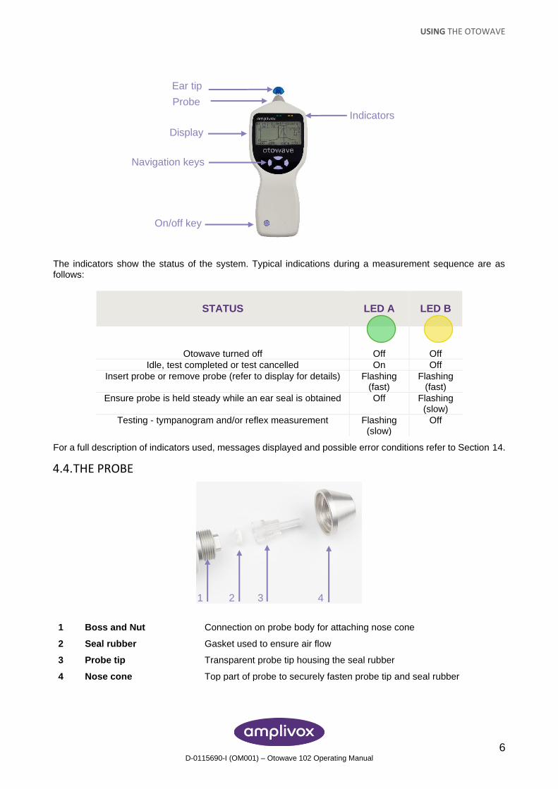
4.3. CONTROLS AND INDICATORS
Press the On/Off key momentarily to turn the Otowave on or off (refer to the diagram below).
Please note: This instrument is equipped with a real-time clock. Before use, please set the date & time to local values in order to ensure that test data and calibration status are correctly identified. Refer to Section 6.
No warm-up time is required, although a short diagnostic routine will run for a few seconds. During this time the internal pump will operate. To switch off, again press the On/Off key momentarily.
Press the up ▲ and down ▼ navigation keys to scroll through the menus or set values
Press the right navigation key ► to accept a menu choice or go to the next step.
Press the left navigation key ◄ to cancel an operation or go back to the previous step.
The function of the left and right keys is usually shown on the bottom line of the display.
When not performing a test the Otowave 102 will switch off automatically after 90 or 180 seconds if no key is pressed (see Section 6 to make this selection).
WARNING
USING THE OTOWAVE
6 D-0115690-I (OM001) – Otowave 102 Operating Manual
The indicators show the status of the system. Typical indications during a measurement sequence are as follows:
STATUS LED A LED B
Otowave turned off
Off
Off
Idle, test completed or test cancelled On Off
Insert probe or remove probe (refer to display for details) Flashing (fast)
Flashing (fast)
Ensure probe is held steady while an ear seal is obtained Off Flashing (slow)
Testing - tympanogram and/or reflex measurement Flashing (slow)
Off
For a full description of indicators used, messages displayed and possible error conditions refer to Section 14.
4.4. THE PROBE
1 Boss and Nut Connection on probe body for attaching nose cone
2 Seal rubber Gasket used to ensure air flow
3 Probe tip Transparent probe tip housing the seal rubber
4 Nose cone Top part of probe to securely fasten probe tip and seal rubber
Ear tip
Probe
Display
Navigation keys
On/off key
Indicators
1 2 3 4
USING THE OTOWAVE
7 D-0115690-I (OM001) – Otowave 102 Operating Manual
The small holes through the Otowave probe tip must be kept clear. If these become blocked a warning message will be displayed. The probe tip must be replaced.
To remove the probe tip, unscrew the nose cone and remove the probe tip from the boss. A small seal will be found in the base of the probe tip. This should be examined and replaced if it is blocked or damaged. Do not remove the nut securing the boss to the body of the instrument.
Please note: When replacing the probe tip, ensure that the seal is correctly located with the flat side aligned with the flat side within the base of the probe tip. Push the probe tip over the boss and replace the nose cone. Make sure that the nose cone is screwed home firmly but do not over-tighten. Do not use any tools to tighten the nose cone.
After replacing the tip a Daily Check should be carried out (see Section 11).
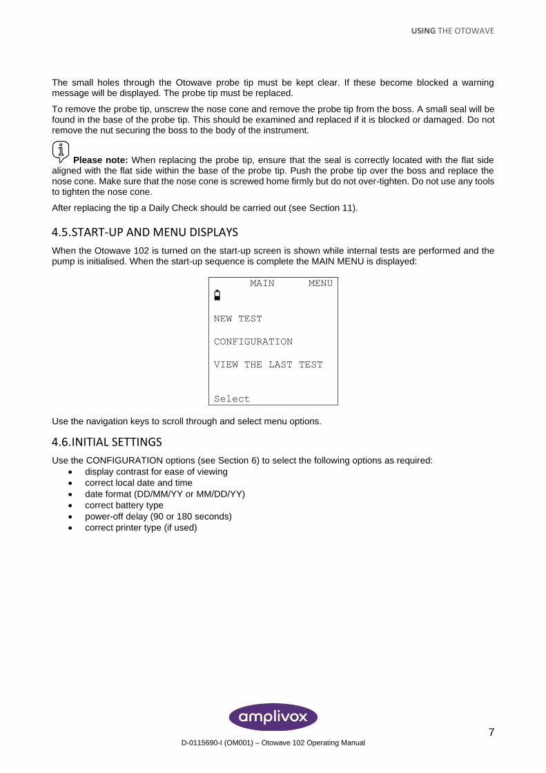
4.5. START-UP AND MENU DISPLAYS
When the Otowave 102 is turned on the start-up screen is shown while internal tests are performed and the pump is initialised. When the start-up sequence is complete the MAIN MENU is displayed:
MAIN MENU
NEW TEST
CONFIGURATION
VIEW THE LAST TEST
Select
Use the navigation keys to scroll through and select menu options.
4.6. INITIAL SETTINGS
Use the CONFIGURATION options (see Section 6) to select the following options as required:
• display contrast for ease of viewing
• correct local date and time
• date format (DD/MM/YY or MM/DD/YY)
• correct battery type
• power-off delay (90 or 180 seconds)
• correct printer type (if used)
TAKING MEASUREMENTS
8 D-0115690-I (OM001) – Otowave 102 Operating Manual
5. TAKING MEASUREMENTS
5.1. PRIOR TO TESTING AND AMBIENT CONDITIONS
A suitably-qualified health care professional should perform a thorough otoscopic examination to establish that the condition of the ear is suitable for the test options selected and that no contraindications are present. The latter would include obstruction of the external ear canal due to excessive wax and/or hairs, both of which would need to be removed.
Tympanometric and reflex testing should always be performed in a quiet room or in an acoustic booth.
5.2. EAR TIP(S)
Video available on how to choose the right ear tip.
These must be selected and fitted by a practitioner qualified to perform tympanometric tests.
Please note: The probe tip must be fitted with a new ear tip before it is presented to a patient’s ear canal. The ear tip must be fitted completely to the probe tip and must not occlude any of the four holes in the probe tip. The ear tip size is chosen to suit the patient’s ear and provide a comfortable pressure seal.
Refer to Section 16 regarding these single-use parts.
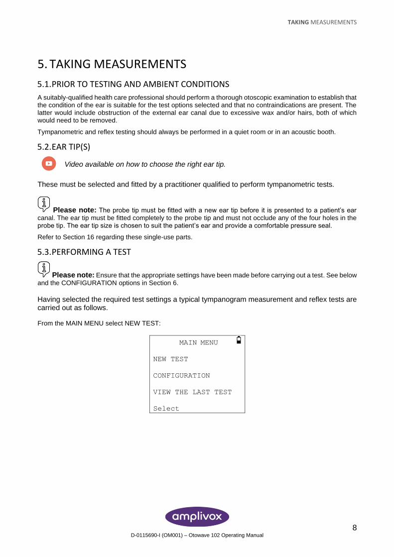
5.3. PERFORMING A TEST
Please note: Ensure that the appropriate settings have been made before carrying out a test. See below and the CONFIGURATION options in Section 6.
Having selected the required test settings a typical tympanogram measurement and reflex tests are carried out as follows. From the MAIN MENU select NEW TEST:
MAIN MENU
NEW TEST
CONFIGURATION
VIEW THE LAST TEST
Select
TAKING MEASUREMENTS
9 D-0115690-I (OM001) – Otowave 102 Operating Manual
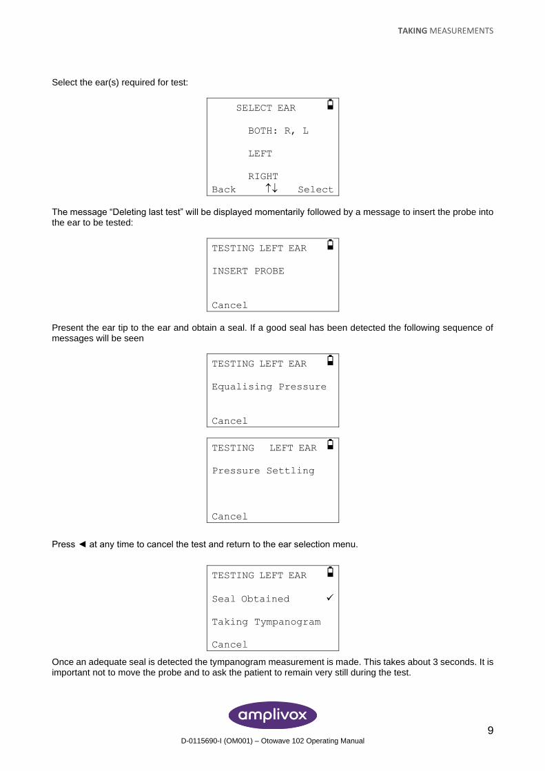
Select the ear(s) required for test:
SELECT EAR
BOTH: R, L
LEFT
RIGHT
Back Select
The message “Deleting last test” will be displayed momentarily followed by a message to insert the probe into the ear to be tested:
TESTING LEFT EAR
INSERT PROBE
Cancel
Present the ear tip to the ear and obtain a seal. If a good seal has been detected the following sequence of messages will be seen
TESTING LEFT EAR
Equalising Pressure
Cancel
TESTING LEFT EAR
Pressure Settling
Cancel
Press ◄ at any time to cancel the test and return to the ear selection menu.
TESTING LEFT EAR
Seal Obtained ✓
Taking Tympanogram
Cancel
Once an adequate seal is detected the tympanogram measurement is made. This takes about 3 seconds. It is important not to move the probe and to ask the patient to remain very still during the test.
TAKING MEASUREMENTS
10 D-0115690-I (OM001) – Otowave 102 Operating Manual
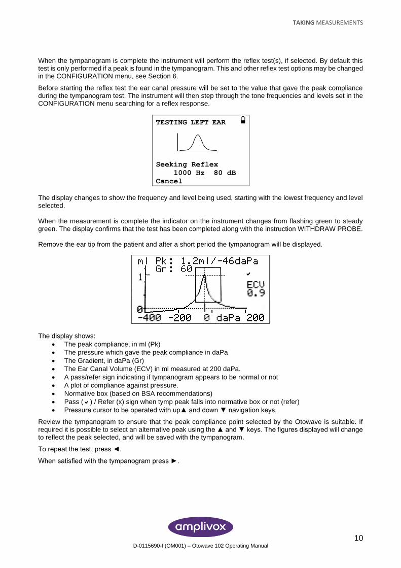
When the tympanogram is complete the instrument will perform the reflex test(s), if selected. By default this test is only performed if a peak is found in the tympanogram. This and other reflex test options may be changed in the CONFIGURATION menu, see Section 6.
Before starting the reflex test the ear canal pressure will be set to the value that gave the peak compliance during the tympanogram test. The instrument will then step through the tone frequencies and levels set in the CONFIGURATION menu searching for a reflex response.
TESTING LEFT EAR
Seeking Reflex
1000 Hz 80 dB
Cancel
The display changes to show the frequency and level being used, starting with the lowest frequency and level selected. When the measurement is complete the indicator on the instrument changes from flashing green to steady green. The display confirms that the test has been completed along with the instruction WITHDRAW PROBE. Remove the ear tip from the patient and after a short period the tympanogram will be displayed.
The display shows:
• The peak compliance, in ml (Pk)
• The pressure which gave the peak compliance in daPa
• The Gradient, in daPa (Gr)
• The Ear Canal Volume (ECV) in ml measured at 200 daPa.
• A pass/refer sign indicating if tympanogram appears to be normal or not
• A plot of compliance against pressure.
• Normative box (based on BSA recommendations)
• Pass () / Refer (x) sign when tymp peak falls into normative box or not (refer)
• Pressure cursor to be operated with up▲ and down ▼ navigation keys.
Review the tympanogram to ensure that the peak compliance point selected by the Otowave is suitable. If required it is possible to select an alternative peak using the ▲ and ▼ keys. The figures displayed will change to reflect the peak selected, and will be saved with the tympanogram.
To repeat the test, press ◄.
When satisfied with the tympanogram press ►.
TAKING MEASUREMENTS
11 D-0115690-I (OM001) – Otowave 102 Operating Manual
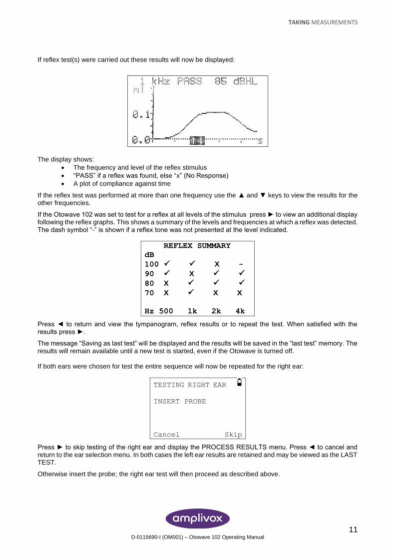
If reflex test(s) were carried out these results will now be displayed:
The display shows:
• The frequency and level of the reflex stimulus
• “PASS” if a reflex was found, else “x” (No Response)
• A plot of compliance against time
If the reflex test was performed at more than one frequency use the ▲ and ▼ keys to view the results for the other frequencies.
If the Otowave 102 was set to test for a reflex at all levels of the stimulus press ► to view an additional display following the reflex graphs. This shows a summary of the levels and frequencies at which a reflex was detected. The dash symbol “-” is shown if a reflex tone was not presented at the level indicated.
REFLEX SUMMARY
dB
100 ✓ ✓ X -
90 ✓ X ✓ ✓
80 X ✓ ✓ ✓
70 X ✓ X X
Hz 500 1k 2k 4k
Press ◄ to return and view the tympanogram, reflex results or to repeat the test. When satisfied with the results press ►.
The message “Saving as last test” will be displayed and the results will be saved in the “last test” memory. The results will remain available until a new test is started, even if the Otowave is turned off. If both ears were chosen for test the entire sequence will now be repeated for the right ear:
TESTING RIGHT EAR
INSERT PROBE
Cancel Skip
Press ► to skip testing of the right ear and display the PROCESS RESULTS menu. Press ◄ to cancel and return to the ear selection menu. In both cases the left ear results are retained and may be viewed as the LAST TEST.
Otherwise insert the probe; the right ear test will then proceed as described above.
TAKING MEASUREMENTS
12 D-0115690-I (OM001) – Otowave 102 Operating Manual
When the selected ears have been tested and the results saved the PROCESS RESULTS menu will be displayed. This accesses the following functions:
• Print the results
• Send the results to a computer
• Save the results in the internal database
• Review the results as described above
• Return to the main menu
The results of the last test performed remain available even if the Otowave has been turned off. To view these results select VIEW THE LAST TEST from the main menu. After selecting the required ear the tympanogram will be displayed. It will then be possible to view the results and select the PROCESS RESULTS menu as if the test had just been completed.
Please note: Results of the last test will be erased as soon as a new test is started. Test results should be saved to the Otowave’s database, printed or sent to a computer to ensure that data is not lost.
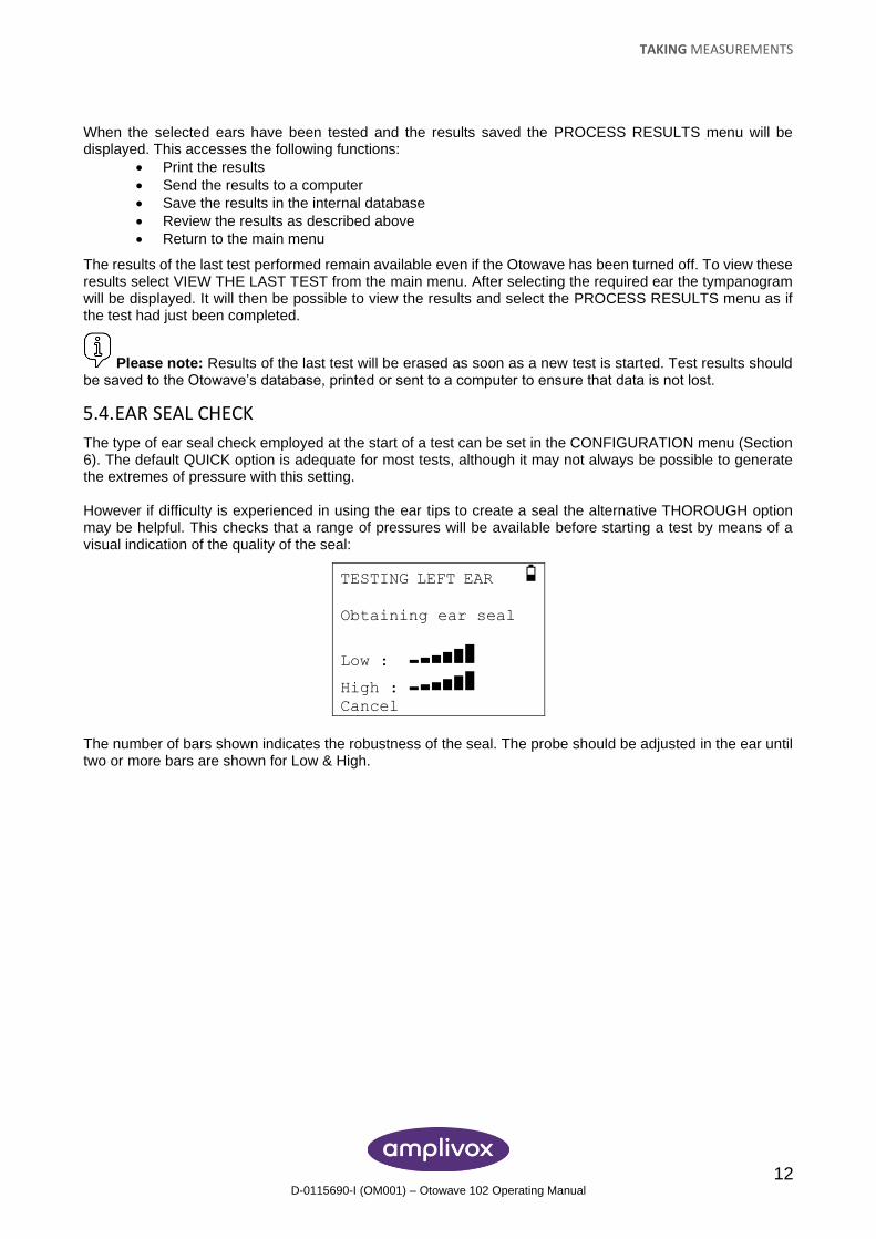
5.4. EAR SEAL CHECK
The type of ear seal check employed at the start of a test can be set in the CONFIGURATION menu (Section 6). The default QUICK option is adequate for most tests, although it may not always be possible to generate the extremes of pressure with this setting. However if difficulty is experienced in using the ear tips to create a seal the alternative THOROUGH option may be helpful. This checks that a range of pressures will be available before starting a test by means of a visual indication of the quality of the seal:
TESTING LEFT EAR
Obtaining ear seal
Low :
High :
Cancel
The number of bars shown indicates the robustness of the seal. The probe should be adjusted in the ear until two or more bars are shown for Low & High.
TAKING MEASUREMENTS
13 D-0115690-I (OM001) – Otowave 102 Operating Manual
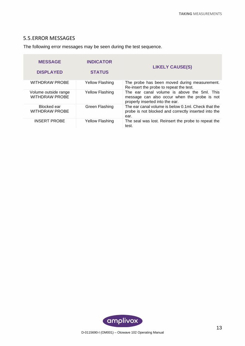
5.5. ERROR MESSAGES
The following error messages may be seen during the test sequence.
MESSAGE
DISPLAYED
INDICATOR
STATUS LIKELY CAUSE(S)
WITHDRAW PROBE Yellow Flashing The probe has been moved during measurement. Re-insert the probe to repeat the test.
Volume outside range WITHDRAW PROBE
Yellow Flashing The ear canal volume is above the 5ml. This message can also occur when the probe is not properly inserted into the ear.
Blocked ear WITHDRAW PROBE
Green Flashing The ear canal volume is below 0.1ml. Check that the probe is not blocked and correctly inserted into the ear.
INSERT PROBE Yellow Flashing The seal was lost. Reinsert the probe to repeat the test.
CONFIGURATION
14 D-0115690-I (OM001) – Otowave 102 Operating Manual
6. CONFIGURATION
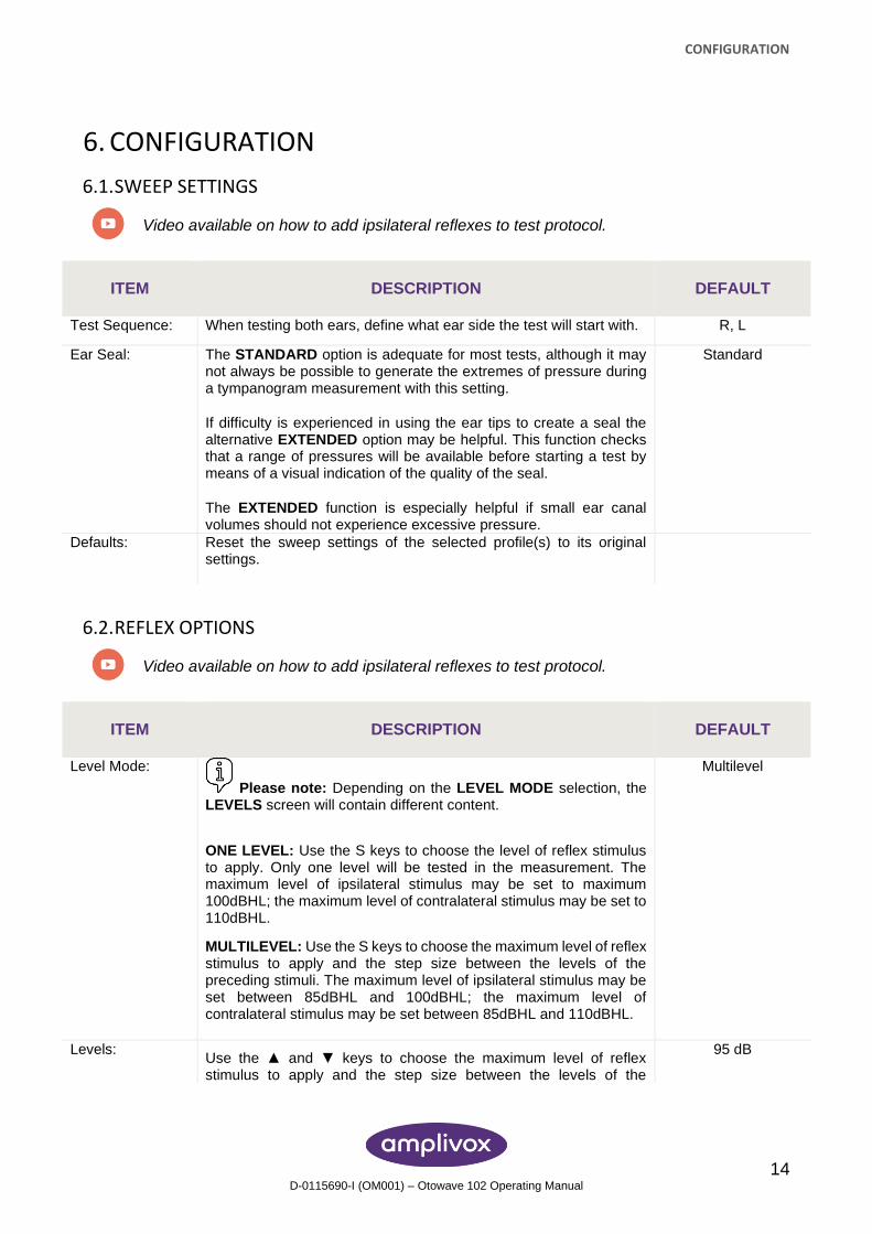
6.1. SWEEP SETTINGS
Video available on how to add ipsilateral reflexes to test protocol.
ITEM DESCRIPTION DEFAULT
Test Sequence: When testing both ears, define what ear side the test will start with. R, L
Ear Seal: The STANDARD option is adequate for most tests, although it may not always be possible to generate the extremes of pressure during a tympanogram measurement with this setting.
If difficulty is experienced in using the ear tips to create a seal the alternative EXTENDED option may be helpful. This function checks that a range of pressures will be available before starting a test by means of a visual indication of the quality of the seal.
The EXTENDED function is especially helpful if small ear canal volumes should not experience excessive pressure.
Standard
Defaults: Reset the sweep settings of the selected profile(s) to its original settings.
6.2. REFLEX OPTIONS
Video available on how to add ipsilateral reflexes to test protocol.
ITEM DESCRIPTION DEFAULT
Level Mode:
Please note: Depending on the LEVEL MODE selection, the LEVELS screen will contain different content.
ONE LEVEL: Use the S keys to choose the level of reflex stimulus to apply. Only one level will be tested in the measurement. The maximum level of ipsilateral stimulus may be set to maximum 100dBHL; the maximum level of contralateral stimulus may be set to 110dBHL.
MULTILEVEL: Use the S keys to choose the maximum level of reflex stimulus to apply and the step size between the levels of the preceding stimuli. The maximum level of ipsilateral stimulus may be set between 85dBHL and 100dBHL; the maximum level of contralateral stimulus may be set between 85dBHL and 110dBHL.
Multilevel
Levels: Use the ▲ and ▼ keys to choose the maximum level of reflex stimulus to apply and the step size between the levels of the
95 dB
CONFIGURATION
15 D-0115690-I (OM001) – Otowave 102 Operating Manual
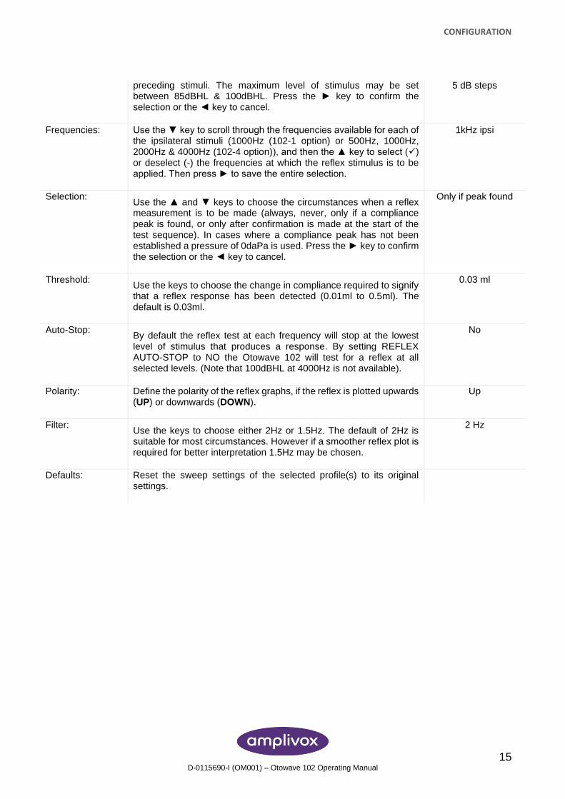
preceding stimuli. The maximum level of stimulus may be set between 85dBHL & 100dBHL. Press the ► key to confirm the selection or the ◄ key to cancel.
5 dB steps
Frequencies: Use the ▼ key to scroll through the frequencies available for each of the ipsilateral stimuli (1000Hz (102-1 option) or 500Hz, 1000Hz, 2000Hz & 4000Hz (102-4 option)), and then the ▲ key to select (✓) or deselect (-) the frequencies at which the reflex stimulus is to be applied. Then press ► to save the entire selection.
1kHz ipsi
Selection: Use the ▲ and ▼ keys to choose the circumstances when a reflex measurement is to be made (always, never, only if a compliance peak is found, or only after confirmation is made at the start of the test sequence). In cases where a compliance peak has not been established a pressure of 0daPa is used. Press the ► key to confirm the selection or the ◄ key to cancel.
Only if peak found
Threshold: Use the keys to choose the change in compliance required to signify that a reflex response has been detected (0.01ml to 0.5ml). The default is 0.03ml.
0.03 ml
Auto-Stop: By default the reflex test at each frequency will stop at the lowest level of stimulus that produces a response. By setting REFLEX AUTO-STOP to NO the Otowave 102 will test for a reflex at all selected levels. (Note that 100dBHL at 4000Hz is not available).
No
Polarity: Define the polarity of the reflex graphs, if the reflex is plotted upwards (UP) or downwards (DOWN).
Up
Filter: Use the keys to choose either 2Hz or 1.5Hz. The default of 2Hz is suitable for most circumstances. However if a smoother reflex plot is required for better interpretation 1.5Hz may be chosen.
2 Hz
Defaults: Reset the sweep settings of the selected profile(s) to its original settings.
CONFIGURATION
16 D-0115690-I (OM001) – Otowave 102 Operating Manual
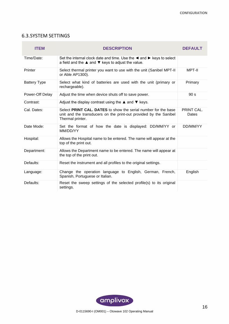
6.3. SYSTEM SETTINGS
ITEM DESCRIPTION DEFAULT
Time/Date: Set the internal clock date and time. Use the ◄ and ► keys to select a field and the ▲ and ▼ keys to adjust the value.
Printer Select thermal printer you want to use with the unit (Sanibel MPT-II or Able AP1300).
MPT-II
Battery Type Select what kind of batteries are used with the unit (primary or rechargeable).
Primary
Power-Off Delay Adjust the time when device shuts off to save power. 90 s
Contrast: Adjust the display contrast using the ▲ and ▼ keys.
Cal. Dates: Select PRINT CAL. DATES to show the serial number for the base unit and the transducers on the print-out provided by the Sanibel Thermal printer.
PRINT CAL. Dates
Date Mode: Set the format of how the date is displayed: DD/MM/YY or MM/DD/YY
DD/MM/YY
Hospital: Allows the Hospital name to be entered. The name will appear at the top of the print out.
Department: Allows the Department name to be entered. The name will appear at the top of the print out.
Defaults: Reset the instrument and all profiles to the original settings.
Language: Change the operation language to English, German, French, Spanish, Portuguese or Italian.
English
Defaults: Reset the sweep settings of the selected profile(s) to its original settings.
SAVING RESULTS IN THE INTERNAL DATABASE
17 D-0115690-I (OM001) – Otowave 102 Operating Manual
7. SAVING RESULTS IN THE INTERNAL DATABASE
7.1. GENERAL
Up to 32 tests can be saved in the Otowave 102 internal database.
To save the results of a test select SAVE RESULTS from the PROCESS RESULTS menu that is displayed on completion of a test. This option can also be accessed by selecting VIEW THE LAST TEST from the main menu and scrolling through the results using the ► key as long as the test results have not already been saved or deleted (e.g. by starting and then aborting a new test).
A three character identifier is used for the record. This is also used as the reference for the patient’s name on the printed record and for data transferred to a computer. The identifier would typically be the patient’s initials, and as the tympanometer uses a combination of this identifier and the date/time of a test to refer to stored records this same identifier may be used for different tests for the same patient.
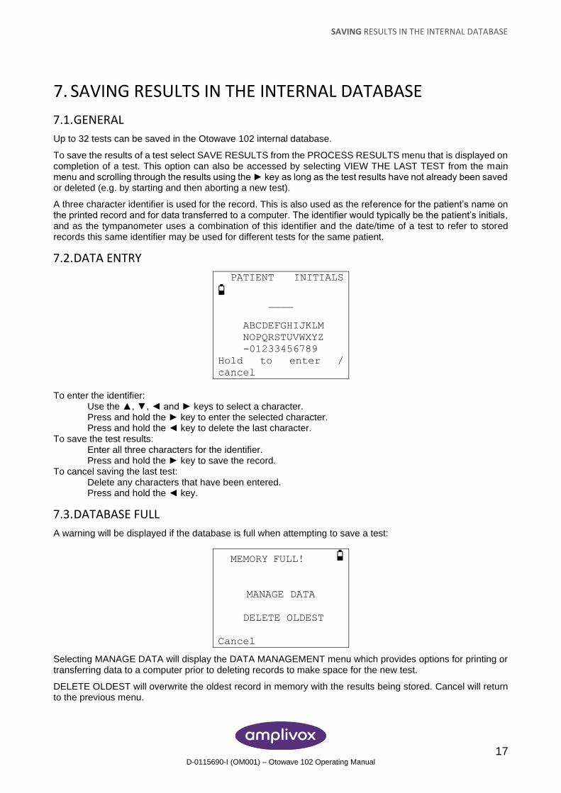
7.2. DATA ENTRY
PATIENT INITIALS
____
ABCDEFGHIJKLM
NOPQRSTUVWXYZ
-01233456789
Hold to enter /
cancel
To enter the identifier:
Use the ▲, ▼, ◄ and ► keys to select a character. Press and hold the ► key to enter the selected character. Press and hold the ◄ key to delete the last character.
To save the test results: Enter all three characters for the identifier. Press and hold the ► key to save the record.
To cancel saving the last test: Delete any characters that have been entered. Press and hold the ◄ key.
7.3. DATABASE FULL
A warning will be displayed if the database is full when attempting to save a test:
MEMORY FULL!
MANAGE DATA
DELETE OLDEST
Cancel
Selecting MANAGE DATA will display the DATA MANAGEMENT menu which provides options for printing or transferring data to a computer prior to deleting records to make space for the new test.
DELETE OLDEST will overwrite the oldest record in memory with the results being stored. Cancel will return to the previous menu.
IRDA COMMUNICATIONS
18 D-0115690-I (OM001) – Otowave 102 Operating Manual
8. IRDA COMMUNICATIONS The Otowave 102 can send test results to a designated printer or a suitably-equipped computer via an infra-red link.
If the computer does not have an infra-red port a suitable infra-red adapter will be required. The Actysis ACT-IR2000U USB adapter is specified for and has been tested for use with the Otowave 102. This adapter may be purchased from Amplivox and only this device should be used for this purpose.
The Otowave sends data through a small window on the right of the probe. For a printer the data is received through a window in the front of the printer; for a computer the data is received through a window located either on the case or on the plug-in adapter if this is used.
The environment in which the Otowave is used can affect the data transfer process. The following are recommendations but may need to be modified depending on the environment.
• The two communication windows should be in line and pointing directly at each other, 10-20cm apart
• Both units must be out of direct sunlight for optimum communication
• For transferring data to a printer ensure that no computer or printer other than the one to be used is within range
• Similarly, for transferring data to a computer ensure that no other IrDA device is within range
• The infra-red link must not be broken once a connection between the printer/computer and the Otowave has been established
• If the printer/computer or Otowave are moved, or an object between them breaks the link, the data may become corrupted or the Otowave may not respond to the controls until the data transfer process has timed-out (this could take 30 to 40 seconds); this may also occur if the printer batteries are discharged while attempting to print
Once the data transfer process has timed-out the resulting error message can be cleared and the data re-sent; if the data is still corrupted select Cancel on the Otowave and then send the data again.
TRANSFERRING THE RESULTS
19 D-0115690-I (OM001) – Otowave 102 Operating Manual
9. TRANSFERRING THE RESULTS
9.1. SENDING THE RESULTS TO A PRINTER
Video available on how send results to a printer.
Two designated thermal printers (the Able AP1300 or the Sanibel MPT-II) are available as options and only these printers should be used. Printers supplied with the Otowave 102 are correctly configured for communication but it is important to ensure that the correct printer is selected .
The Able and Sanibel printers have no user-settable configuration options.
Before attempting to print ensure the printer is fully charged, switched on, loaded with paper and ready to print.
To print the results of the last test select SEND TO PRINTER from the PROCESS RESULTS menu on completion of the test. (Similar facilities for printing are available from the VIEW THE LAST TEST and DATA MANAGEMENT options in the MAIN MENU.)
Press ◄ to cancel printing.
The three character identifier for the record is printed in the “Name” field followed by the Otowave graphical displays, the analysis and the results. The name of the hospital, the department, and the calibration dates for the instrument may also be printed if required.There is space for additional details to be handwritten by the clinician (patient name/age, operator & comments).
Thermal paper printouts can fade with exposure to light or heat. Consider transferring the data to a computer for permanent storage.
9.2. DATA TRANSFER TO NOAH OR AMPLISUITE
To transfer test results stored within the tympanometer to a NOAH database the Amplivox NOAH Impedance module must be installed on to a computer. Alternatively, Amplivox ampliSuite allows data to be transferred to a computer and subsequently viewed, annotated & printed. This software is supplied on a USB which includes this operating manual.
Refer to the installation & operating instructions provided with the NOAH Impedance Module or ampliSuite for further details.
If communication between the Otowave 102 and the computer cannot be established the message “Device not found” is displayed. The following points should be checked:
• Ensure the environment is suitable
• The computer has its IrDA software properly installed and the interface enabled
• If the computer has been in “Hibernate” mode the IrDA interface is not always re-enabled; try restarting the computer
• The IrDA adapter on the computer is compatible with the Otowave
• Turn the Otowave off and on again before trying to send the data again If communication is lost while sending the data the message “Link was unreliable” will be displayed. Press ◄ to cancel sending the data and start the operation again.
If any other messages are displayed while sending data, turn the Otowave off and then on again and try re-sending the data. If the problem persists contact an Amplivox service centre.
DATA MANAGEMENT
20 D-0115690-I (OM001) – Otowave 102 Operating Manual
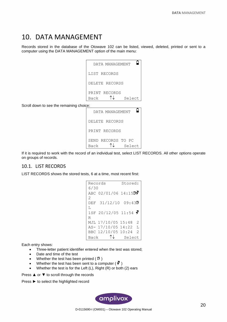
10. DATA MANAGEMENT Records stored in the database of the Otowave 102 can be listed, viewed, deleted, printed or sent to a computer using the DATA MANAGEMENT option of the main menu:
DATA MANAGEMENT
LIST RECORDS
DELETE RECORDS
PRINT RECORDS
Back Select
Scroll down to see the remaining choice:
DATA MANAGEMENT
DELETE RECORDS
PRINT RECORDS
SEND RECORDS TO PC
Back Select
If it is required to work with the record of an individual test, select LIST RECORDS. All other options operate on groups of records.
10.1. LIST RECORDS
LIST RECORDS shows the stored tests, 6 at a time, most recent first:
Records Stored:
6/30
ABC 02/01/06 14:15
2
DEF 31/12/10 09:43
L
1SF 20/12/05 11:54
R
MJL 17/10/05 15:48 2
AS- 17/10/05 14:22 L
BBC 12/10/05 10:24 2
Back Select
Each entry shows:
• Three-letter patient identifier entered when the test was stored;
• Date and time of the test
• Whether the test has been printed ( )
• Whether the test has been sent to a computer ( )
• Whether the test is for the Left (L), Right (R) or both (2) ears
Press ▲ or ▼ to scroll through the records
Press ► to select the highlighted record
DATA MANAGEMENT
21 D-0115690-I (OM001) – Otowave 102 Operating Manual
Press ◄ to return to the previous menu
When a record is selected the PROCESS RECORD menu will be displayed. This accesses the following functions:
• View the selected record
• Print the selected record
• Send the selected record to a computer
• Delete the selected record
10.2. DELETE RECORDS
DELETE RECORDS allows a group of records to be deleted. It is possible to delete all records, all records that have been printed or all records that have been sent to a computer. Confirmation of the deletion is required.
10.3. PRINT RECORDS
PRINT RECORDS allows a group of records to be sent to the printer. It is possible to print all stored records or just those records that have not already been printed. If printing the entire database it is recommended that a full roll of paper is loaded into the printer.
10.4. SEND RECORDS TO A COMPUTER
SEND RECORDS TO PC allows a group of records to be sent to a computer. It is possible to send all stored records or just those records that have not already been sent.
PERFORMING DAILY CHECKS
22 D-0115690-I (OM001) – Otowave 102 Operating Manual
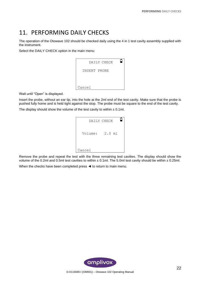
11. PERFORMING DAILY CHECKS The operation of the Otowave 102 should be checked daily using the 4 in 1 test cavity assembly supplied with the instrument.
Select the DAILY CHECK option in the main menu:
DAILY CHECK
INSERT PROBE
Cancel
Wait until “Open” is displayed.
Insert the probe, without an ear tip, into the hole at the 2ml end of the test cavity. Make sure that the probe is pushed fully home and is held tight against the stop. The probe must be square to the end of the test cavity.
The display should show the volume of the test cavity to within ± 0.1ml.
DAILY CHECK
Volume: 2.0 ml
Cancel
Remove the probe and repeat the test with the three remaining test cavities. The display should show the volume of the 0.2ml and 0.5ml test cavities to within ± 0.1ml. The 5.0ml test cavity should be within ± 0.25ml.
When the checks have been completed press ◄ to return to main menu.
SYSTEM INFORMATION
23 D-0115690-I (OM001) – Otowave 102 Operating Manual
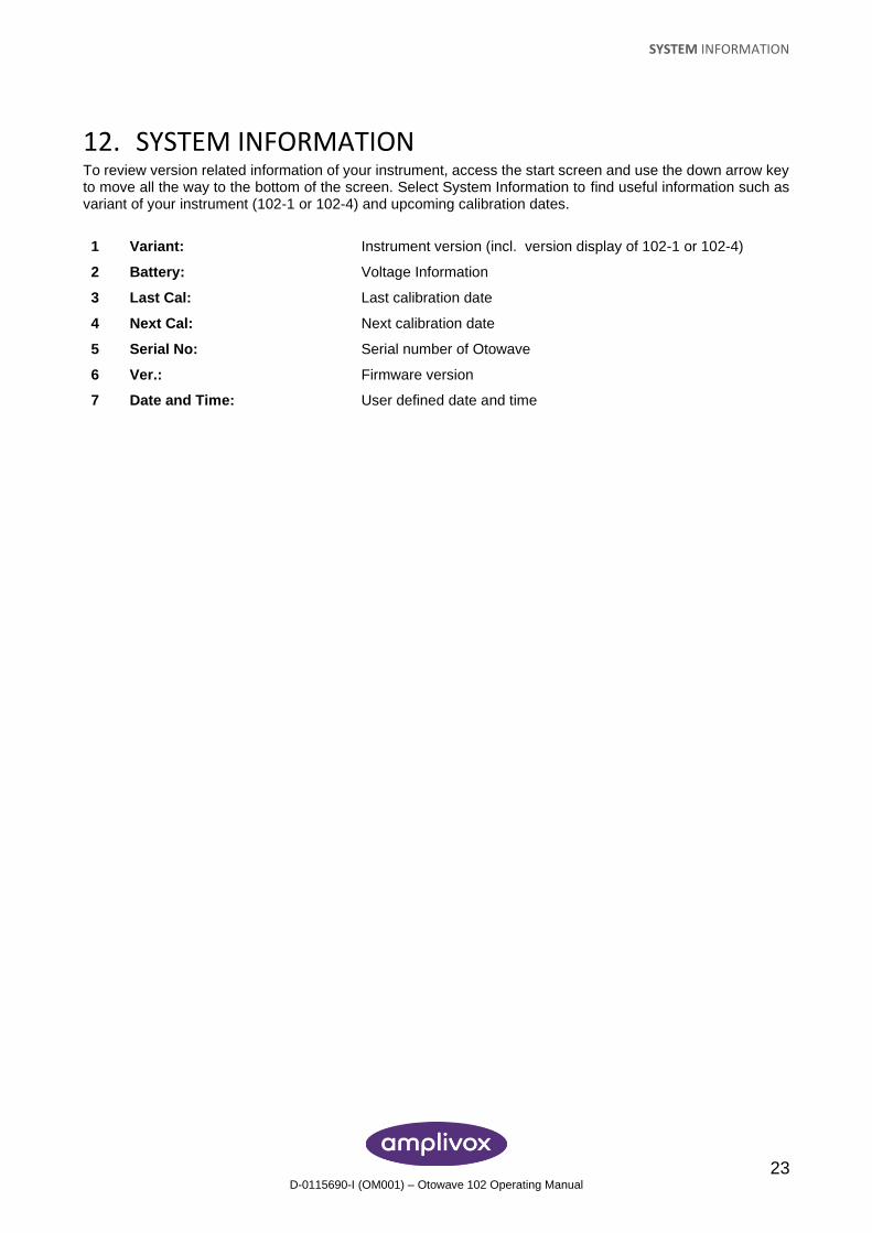
12. SYSTEM INFORMATION To review version related information of your instrument, access the start screen and use the down arrow key to move all the way to the bottom of the screen. Select System Information to find useful information such as variant of your instrument (102-1 or 102-4) and upcoming calibration dates.
1 Variant: Instrument version (incl. version display of 102-1 or 102-4)
2 Battery: Voltage Information
3 Last Cal: Last calibration date
4 Next Cal: Next calibration date
5 Serial No: Serial number of Otowave
6 Ver.: Firmware version
7 Date and Time: User defined date and time
ROUTINE MAINTENANCE
24 D-0115690-I (OM001) – Otowave 102 Operating Manual
13. ROUTINE MAINTENANCE
13.1. CLEANING THE OTOWAVE
The Otowave is a precision instrument. Handle it carefully in order to ensure its continued accuracy and service. Before cleaning the instrument remove the batteries. Use a soft damp cloth and mild detergent to clean the instrument panel and case. Ensure no moisture enters the instrument.
13.2. EAR TIP AND PROBE
Ear tips should be replaced after a single use.
The probe tip and its associated seal are disposable devices.
The probe tip should be checked before each ear insertion to ensure it is undamaged and that none of the tubes through it are blocked. It should be replaced if necessary.
The seal should be replaced when the probe tip is replaced, if it shows signs of wear, or if a pressure leak is suspected.
Handle the probe and accessories with care. Do not allow moisture, condensation, fluids or debris to enter the probe.
13.3. CALIBRATION AND REPAIR OF THE INSTRUMENT
Amplivox recommends that the Otowave is calibrated annually. Please contact Amplivox for details.
If the instrument is to be used at elevations above that specified re-calibration must be undertaken at the intended operating elevation.
The instrument should be returned to the manufacturer for service & repair. There are no user-serviceable parts within it.
Please use the original shipping carton and packaging to transport the instrument. Place the instrument in a plastic bag before packing to prevent dirt and dust getting into the probe. Do not return the batteries with the instrument.
WARNING
WARNING
ERROR MESSAGES & FAULT CONDITIONS
25 D-0115690-I (OM001) – Otowave 102 Operating Manual
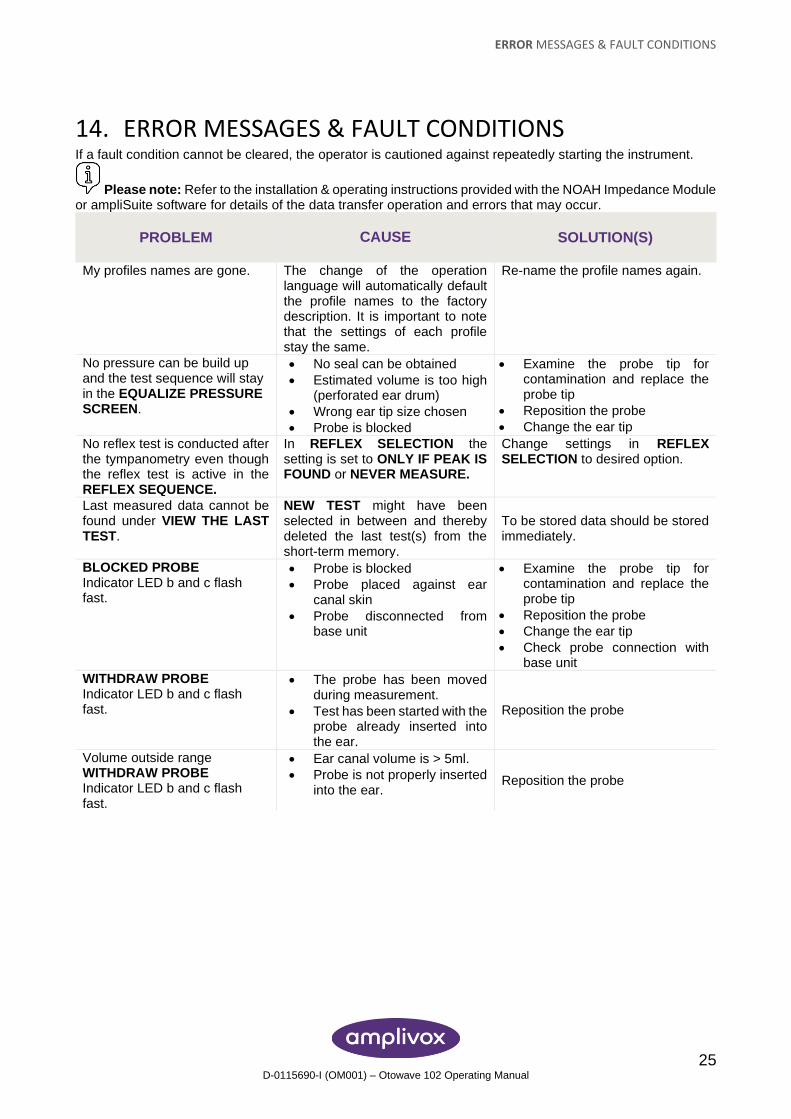
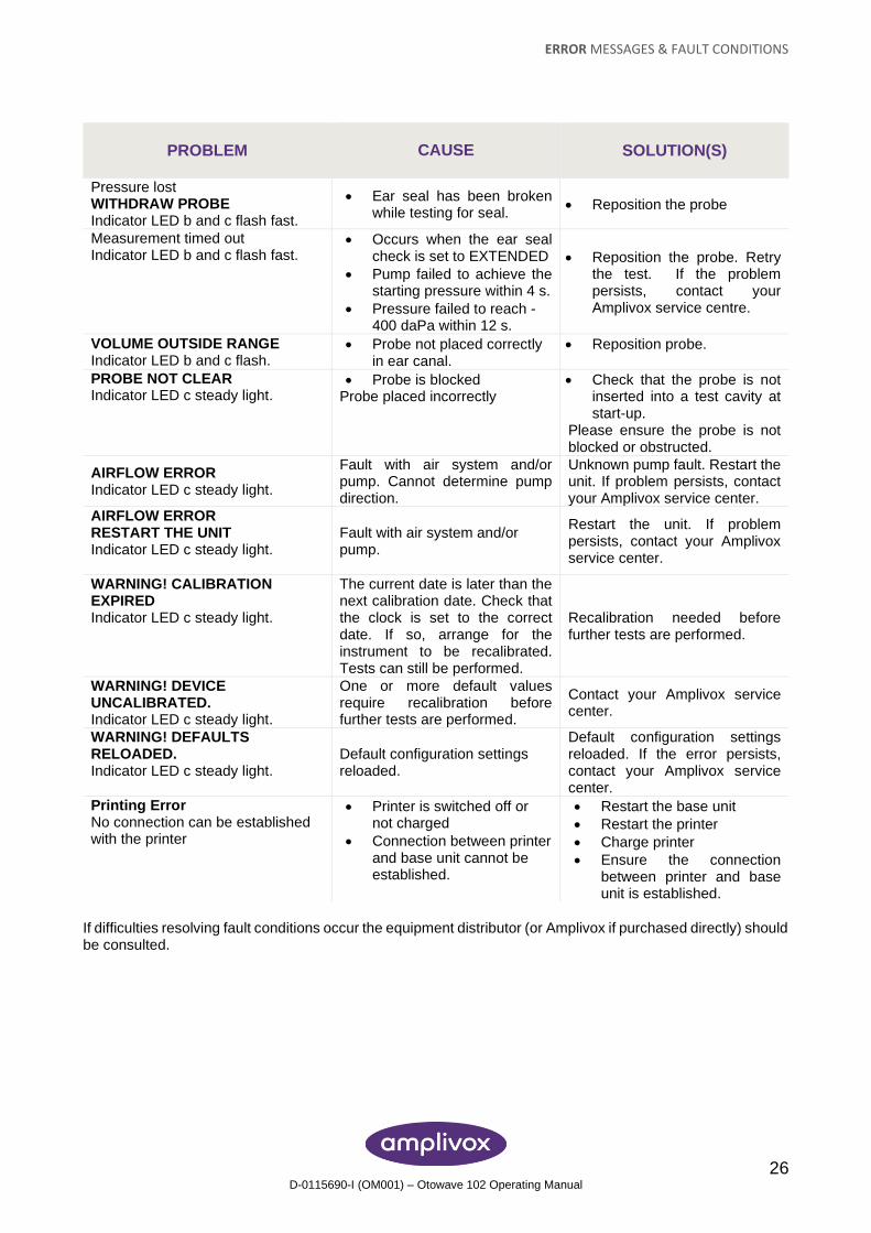
14. ERROR MESSAGES & FAULT CONDITIONS If a fault condition cannot be cleared, the operator is cautioned against repeatedly starting the instrument.
Please note: Refer to the installation & operating instructions provided with the NOAH Impedance Module or ampliSuite software for details of the data transfer operation and errors that may occur.
PROBLEM CAUSE
SOLUTION(S)
My profiles names are gone. The change of the operation language will automatically default the profile names to the factory description. It is important to note that the settings of each profile stay the same.
Re-name the profile names again.
No pressure can be build up and the test sequence will stay in the EQUALIZE PRESSURE SCREEN.
• No seal can be obtained
• Estimated volume is too high (perforated ear drum)
• Wrong ear tip size chosen
• Probe is blocked
• Examine the probe tip for contamination and replace the probe tip
• Reposition the probe
• Change the ear tip
No reflex test is conducted after the tympanometry even though the reflex test is active in the REFLEX SEQUENCE.
In REFLEX SELECTION the setting is set to ONLY IF PEAK IS FOUND or NEVER MEASURE.
Change settings in REFLEX SELECTION to desired option.
Last measured data cannot be found under VIEW THE LAST TEST.
NEW TEST might have been selected in between and thereby deleted the last test(s) from the short-term memory.
To be stored data should be stored immediately.
BLOCKED PROBE Indicator LED b and c flash fast.
• Probe is blocked
• Probe placed against ear canal skin
• Probe disconnected from base unit
• Examine the probe tip for contamination and replace the probe tip
• Reposition the probe
• Change the ear tip
• Check probe connection with base unit
WITHDRAW PROBE Indicator LED b and c flash fast.
• The probe has been moved during measurement.
• Test has been started with the probe already inserted into the ear.
Reposition the probe
Volume outside range WITHDRAW PROBE Indicator LED b and c flash fast.
• Ear canal volume is > 5ml.
• Probe is not properly inserted into the ear.
Reposition the probe
ERROR MESSAGES & FAULT CONDITIONS
26 D-0115690-I (OM001) – Otowave 102 Operating Manual
PROBLEM CAUSE
SOLUTION(S)
Pressure lost WITHDRAW PROBE Indicator LED b and c flash fast.
• Ear seal has been broken while testing for seal.
• Reposition the probe
Measurement timed out Indicator LED b and c flash fast.
• Occurs when the ear seal check is set to EXTENDED
• Pump failed to achieve the starting pressure within 4 s.
• Pressure failed to reach -400 daPa within 12 s.
• Reposition the probe. Retry the test. If the problem persists, contact your Amplivox service centre.
VOLUME OUTSIDE RANGE Indicator LED b and c flash.
• Probe not placed correctly in ear canal.
• Reposition probe.
PROBE NOT CLEAR Indicator LED c steady light.
• Probe is blocked Probe placed incorrectly
• Check that the probe is not inserted into a test cavity at start-up.
Please ensure the probe is not blocked or obstructed.
AIRFLOW ERROR Indicator LED c steady light.
Fault with air system and/or pump. Cannot determine pump direction.
Unknown pump fault. Restart the unit. If problem persists, contact your Amplivox service center.
AIRFLOW ERROR RESTART THE UNIT Indicator LED c steady light.
Fault with air system and/or pump.
Restart the unit. If problem persists, contact your Amplivox service center.
WARNING! CALIBRATION EXPIRED Indicator LED c steady light.
The current date is later than the next calibration date. Check that the clock is set to the correct date. If so, arrange for the instrument to be recalibrated. Tests can still be performed.
Recalibration needed before further tests are performed.
WARNING! DEVICE UNCALIBRATED. Indicator LED c steady light.
One or more default values require recalibration before further tests are performed.
Contact your Amplivox service center.
WARNING! DEFAULTS RELOADED. Indicator LED c steady light.
Default configuration settings reloaded.
Default configuration settings reloaded. If the error persists, contact your Amplivox service center.
Printing Error No connection can be established with the printer
• Printer is switched off or not charged
• Connection between printer and base unit cannot be established.
• Restart the base unit
• Restart the printer
• Charge printer
• Ensure the connection between printer and base unit is established.
If difficulties resolving fault conditions occur the equipment distributor (or Amplivox if purchased directly) should be consulted.
TECHNICAL SPECIFICATION
27 D-0115690-I (OM001) – Otowave 102 Operating Manual
15. TECHNICAL SPECIFICATION
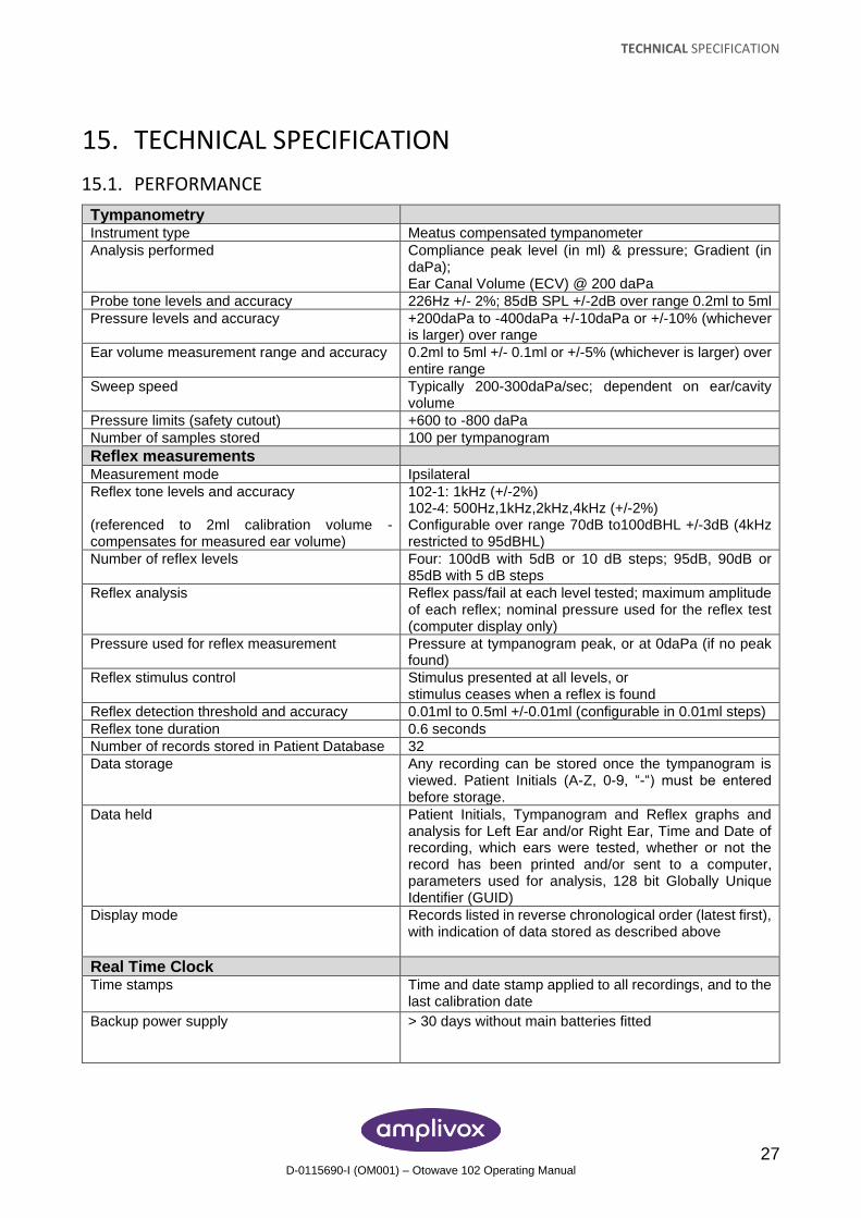
15.1. PERFORMANCE
Tympanometry
Instrument type Meatus compensated tympanometer
Analysis performed Compliance peak level (in ml) & pressure; Gradient (in daPa); Ear Canal Volume (ECV) @ 200 daPa
Probe tone levels and accuracy 226Hz +/- 2%; 85dB SPL +/-2dB over range 0.2ml to 5ml
Pressure levels and accuracy +200daPa to -400daPa +/-10daPa or +/-10% (whichever is larger) over range
Ear volume measurement range and accuracy 0.2ml to 5ml +/- 0.1ml or +/-5% (whichever is larger) over entire range
Sweep speed Typically 200-300daPa/sec; dependent on ear/cavity volume
Pressure limits (safety cutout) +600 to -800 daPa
Number of samples stored 100 per tympanogram
Reflex measurements
Measurement mode Ipsilateral
Reflex tone levels and accuracy (referenced to 2ml calibration volume - compensates for measured ear volume)
102-1: 1kHz (+/-2%) 102-4: 500Hz,1kHz,2kHz,4kHz (+/-2%) Configurable over range 70dB to100dBHL +/-3dB (4kHz restricted to 95dBHL)
Number of reflex levels Four: 100dB with 5dB or 10 dB steps; 95dB, 90dB or 85dB with 5 dB steps
Reflex analysis Reflex pass/fail at each level tested; maximum amplitude of each reflex; nominal pressure used for the reflex test (computer display only)
Pressure used for reflex measurement Pressure at tympanogram peak, or at 0daPa (if no peak found)
Reflex stimulus control Stimulus presented at all levels, or stimulus ceases when a reflex is found
Reflex detection threshold and accuracy 0.01ml to 0.5ml +/-0.01ml (configurable in 0.01ml steps)
Reflex tone duration 0.6 seconds
Number of records stored in Patient Database 32
Data storage Any recording can be stored once the tympanogram is viewed. Patient Initials (A-Z, 0-9, “-“) must be entered before storage.
Data held Patient Initials, Tympanogram and Reflex graphs and analysis for Left Ear and/or Right Ear, Time and Date of recording, which ears were tested, whether or not the record has been printed and/or sent to a computer, parameters used for analysis, 128 bit Globally Unique Identifier (GUID)
Display mode Records listed in reverse chronological order (latest first), with indication of data stored as described above
Real Time Clock
Time stamps Time and date stamp applied to all recordings, and to the last calibration date
Backup power supply > 30 days without main batteries fitted
TECHNICAL SPECIFICATION
28 D-0115690-I (OM001) – Otowave 102 Operating Manual
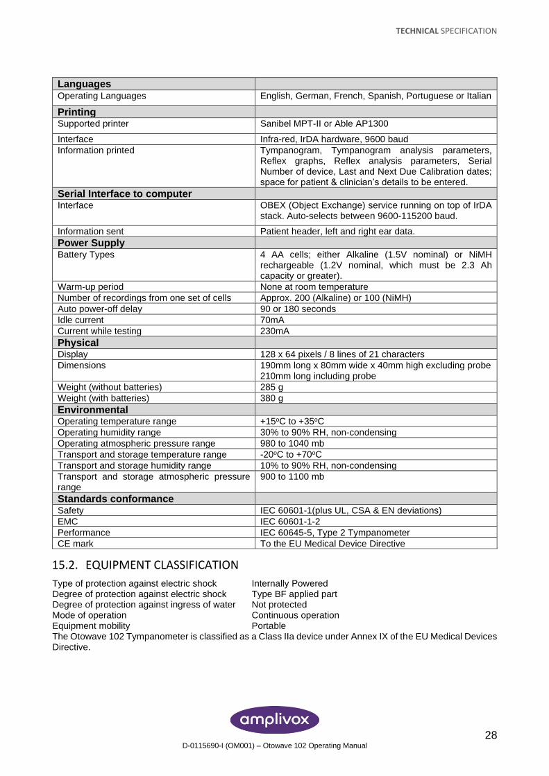
Languages
Operating Languages English, German, French, Spanish, Portuguese or Italian
Printing
Supported printer Sanibel MPT-II or Able AP1300
Interface Infra-red, IrDA hardware, 9600 baud
Information printed Tympanogram, Tympanogram analysis parameters, Reflex graphs, Reflex analysis parameters, Serial Number of device, Last and Next Due Calibration dates; space for patient & clinician’s details to be entered.
Serial Interface to computer Interface OBEX (Object Exchange) service running on top of IrDA
stack. Auto-selects between 9600-115200 baud.
Information sent Patient header, left and right ear data.
Power Supply Battery Types 4 AA cells; either Alkaline (1.5V nominal) or NiMH
rechargeable (1.2V nominal, which must be 2.3 Ah capacity or greater).
Warm-up period None at room temperature
Number of recordings from one set of cells Approx. 200 (Alkaline) or 100 (NiMH)
Auto power-off delay 90 or 180 seconds
Idle current 70mA
Current while testing 230mA
Physical Display 128 x 64 pixels / 8 lines of 21 characters
Dimensions 190mm long x 80mm wide x 40mm high excluding probe 210mm long including probe
Weight (without batteries) 285 g
Weight (with batteries) 380 g
Environmental Operating temperature range +15oC to +35oC
Operating humidity range 30% to 90% RH, non-condensing
Operating atmospheric pressure range 980 to 1040 mb
Transport and storage temperature range -20oC to +70oC
Transport and storage humidity range 10% to 90% RH, non-condensing
Transport and storage atmospheric pressure range
900 to 1100 mb
Standards conformance Safety IEC 60601-1(plus UL, CSA & EN deviations)
EMC IEC 60601-1-2
Performance IEC 60645-5, Type 2 Tympanometer
CE mark To the EU Medical Device Directive
15.2. EQUIPMENT CLASSIFICATION
Type of protection against electric shock Internally Powered Degree of protection against electric shock Type BF applied part Degree of protection against ingress of water Not protected Mode of operation Continuous operation Equipment mobility Portable The Otowave 102 Tympanometer is classified as a Class IIa device under Annex IX of the EU Medical Devices Directive.
TECHNICAL SPECIFICATION
29 D-0115690-I (OM001) – Otowave 102 Operating Manual
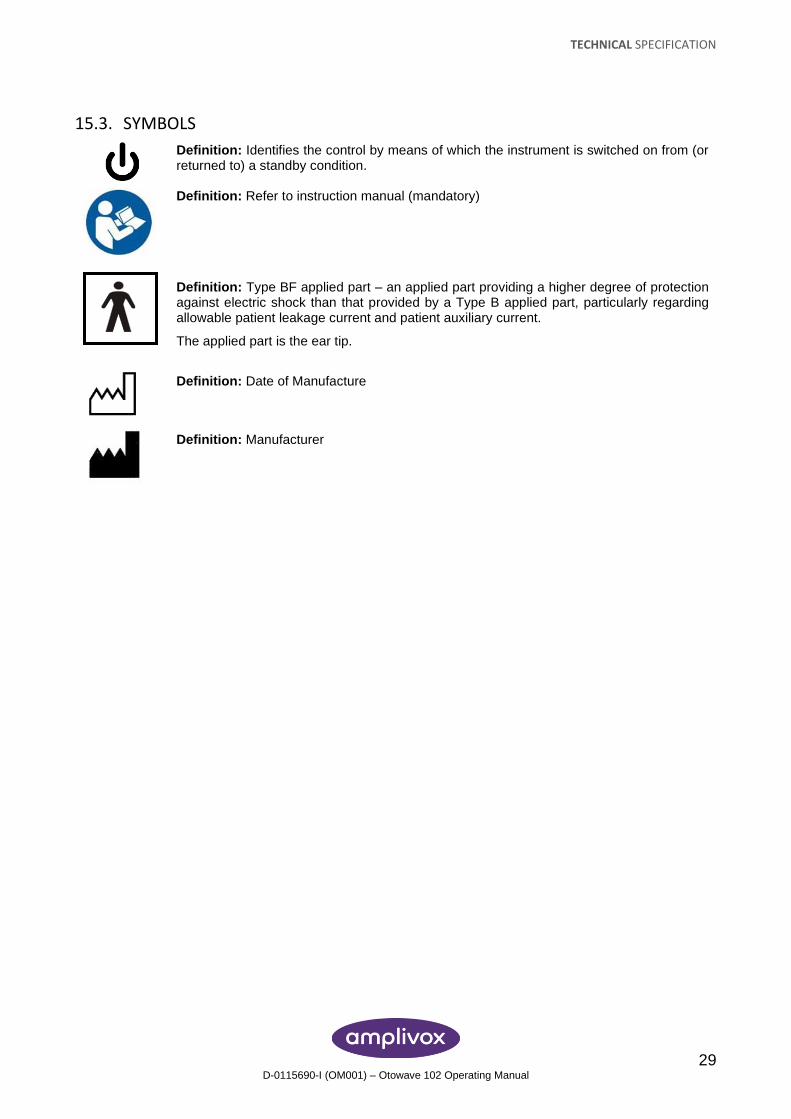
15.3. SYMBOLS
Definition: Identifies the control by means of which the instrument is switched on from (or returned to) a standby condition.
Definition: Refer to instruction manual (mandatory)
Definition: Type BF applied part – an applied part providing a higher degree of protection against electric shock than that provided by a Type B applied part, particularly regarding allowable patient leakage current and patient auxiliary current.
The applied part is the ear tip.
Definition: Date of Manufacture
Definition: Manufacturer
ORDERING CONSUMABLES AND ACCESSORIES
30 D-0115690-I (OM001) – Otowave 102 Operating Manual
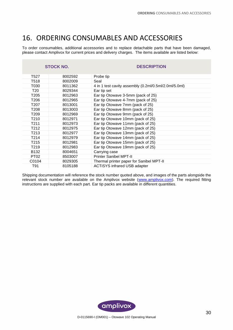
16. ORDERING CONSUMABLES AND ACCESSORIES To order consumables, additional accessories and to replace detachable parts that have been damaged, please contact Amplivox for current prices and delivery charges. The items available are listed below:
STOCK NO. DESCRIPTION
T527 8002592 Probe tip
T518 8002009 Seal
T030 8011362 4 in 1 test cavity assembly (0.2ml/0.5ml/2.0ml/5.0ml)
T20 8029344 Ear tip set
T205 8012963 Ear tip Otowave 3-5mm (pack of 25)
T206 8012965 Ear tip Otowave 4-7mm (pack of 25)
T207 8013001 Ear tip Otowave 7mm (pack of 25)
T208 8013003 Ear tip Otowave 8mm (pack of 25)
T209 8012969 Ear tip Otowave 9mm (pack of 25)
T210 8012971 Ear tip Otowave 10mm (pack of 25)
T211 8012973 Ear tip Otowave 11mm (pack of 25)
T212 8012975 Ear tip Otowave 12mm (pack of 25)
T213 8012977 Ear tip Otowave 13mm (pack of 25)
T214 8012979 Ear tip Otowave 14mm (pack of 25)
T215 8012981 Ear tip Otowave 15mm (pack of 25)
T219 8012983 Ear tip Otowave 19mm (pack of 25)
B132 8004651 Carrying case
PT02 8503007 Printer Sanibel MPT-II
C0104 8029305 Thermal printer paper for Sanibel MPT-II
T91 8105188 ACTiSYS infrared USB adapter
Shipping documentation will reference the stock number quoted above, and images of the parts alongside the relevant stock number are available on the Amplivox website (www.amplivox.com). The required fitting instructions are supplied with each part. Ear tip packs are available in different quantities.
DISPOSAL INFORMATION
31 D-0115690-I (OM001) – Otowave 102 Operating Manual
17. DISPOSAL INFORMATION Amplivox Limited is fully compliant with the WEEE (Waste Electrical and Electronic Equipment) Regulations. Our PRN (Producer Registration Number) is WEE/GA0116XU and we are registered with the approved WEEE Compliance Scheme, B2B Compliance, approval number WEE/MP3338PT/SCH. The main purpose of the WEEE Regulations is to encourage the segregation of waste electrical items from the general waste stream and into reuse, recovery and recycling routes.
Therefore for any waste electrical units purchased from Amplivox that either:
• bear the crossed out wheeled bin symbol with black bar underneath, or
• have been replaced with new Amplivox products on a like-for-like basis please contact our WEEE Compliance Scheme, B2B Compliance, using the details below. B2B Compliance will be able to provide further information on how to recycle your waste electrical units and answer any queries you may have. B2B Compliance Tel: +44 (0) 1691 676 124 (Option 2) Email: [email protected]
EMC GUIDANCE & MANUFACTURER’S DECLARATION
32 D-0115690-I (OM001) – Otowave 102 Operating Manual
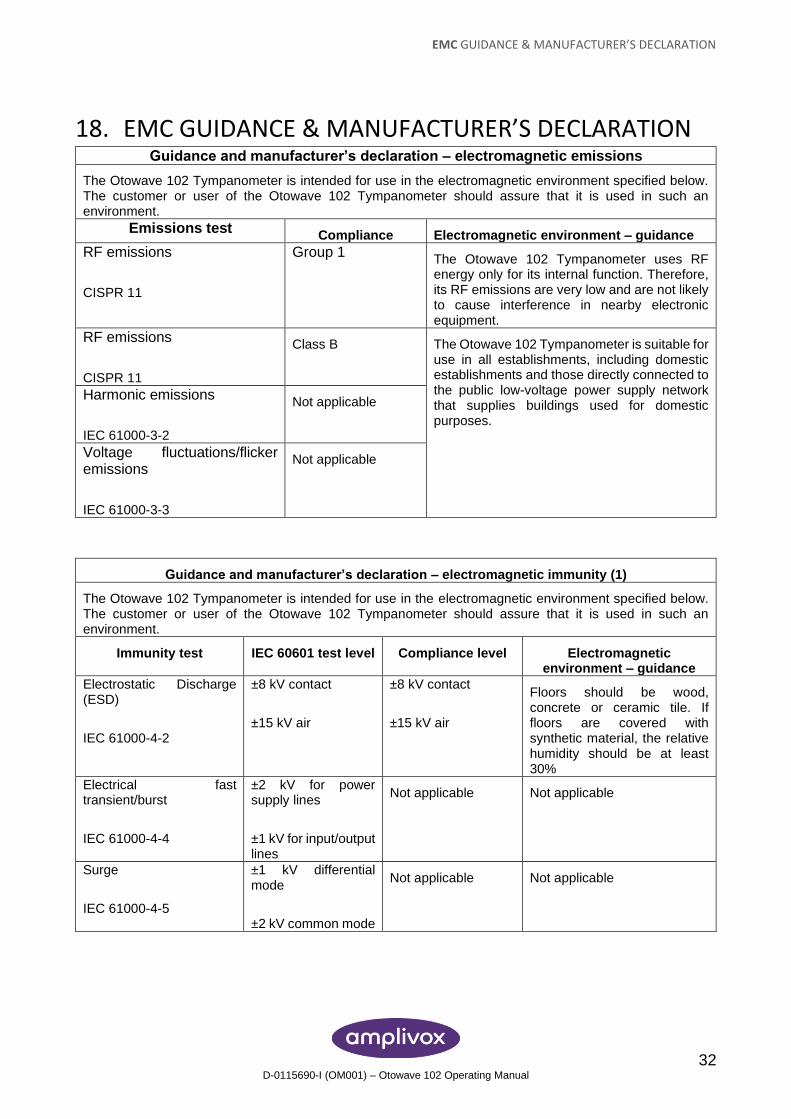
18. EMC GUIDANCE & MANUFACTURER’S DECLARATION Guidance and manufacturer’s declaration – electromagnetic emissions
The Otowave 102 Tympanometer is intended for use in the electromagnetic environment specified below. The customer or user of the Otowave 102 Tympanometer should assure that it is used in such an environment.
Emissions test Compliance Electromagnetic environment – guidance
RF emissions
CISPR 11
Group 1 The Otowave 102 Tympanometer uses RF energy only for its internal function. Therefore, its RF emissions are very low and are not likely to cause interference in nearby electronic equipment.
RF emissions
CISPR 11
Class B The Otowave 102 Tympanometer is suitable for use in all establishments, including domestic establishments and those directly connected to the public low-voltage power supply network that supplies buildings used for domestic purposes.
Harmonic emissions
IEC 61000-3-2
Not applicable
Voltage fluctuations/flicker emissions
IEC 61000-3-3
Not applicable
Guidance and manufacturer’s declaration – electromagnetic immunity (1)
The Otowave 102 Tympanometer is intended for use in the electromagnetic environment specified below. The customer or user of the Otowave 102 Tympanometer should assure that it is used in such an environment.
Immunity test IEC 60601 test level Compliance level Electromagnetic environment – guidance
Electrostatic Discharge (ESD)
IEC 61000-4-2
±8 kV contact
±15 kV air
±8 kV contact
±15 kV air
Floors should be wood, concrete or ceramic tile. If floors are covered with synthetic material, the relative humidity should be at least 30%
Electrical fast transient/burst
IEC 61000-4-4
±2 kV for power supply lines
±1 kV for input/output lines
Not applicable Not applicable
Surge
IEC 61000-4-5
±1 kV differential mode
±2 kV common mode
Not applicable Not applicable
EMC GUIDANCE & MANUFACTURER’S DECLARATION
33 D-0115690-I (OM001) – Otowave 102 Operating Manual
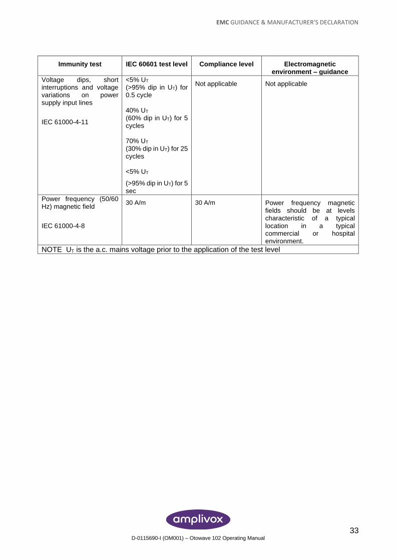
Immunity test IEC 60601 test level Compliance level Electromagnetic environment – guidance
Voltage dips, short interruptions and voltage variations on power supply input lines
IEC 61000-4-11
<5% UT (>95% dip in UT) for 0.5 cycle 40% UT (60% dip in UT) for 5 cycles 70% UT (30% dip in UT) for 25 cycles <5% UT
(>95% dip in UT) for 5 sec
Not applicable Not applicable
Power frequency (50/60 Hz) magnetic field
IEC 61000-4-8
30 A/m 30 A/m Power frequency magnetic fields should be at levels characteristic of a typical location in a typical commercial or hospital environment.
NOTE UT is the a.c. mains voltage prior to the application of the test level
EMC GUIDANCE & MANUFACTURER’S DECLARATION
34 D-0115690-I (OM001) – Otowave 102 Operating Manual
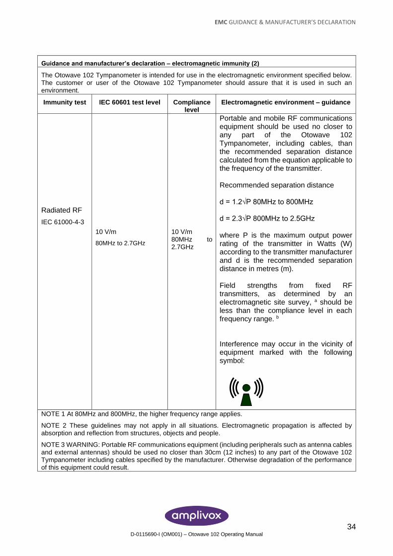
Guidance and manufacturer’s declaration – electromagnetic immunity (2)
The Otowave 102 Tympanometer is intended for use in the electromagnetic environment specified below. The customer or user of the Otowave 102 Tympanometer should assure that it is used in such an environment.
Immunity test IEC 60601 test level Compliance level
Electromagnetic environment – guidance
Radiated RF
IEC 61000-4-3
10 V/m
80MHz to 2.7GHz
10 V/m 80MHz to 2.7GHz
Portable and mobile RF communications equipment should be used no closer to any part of the Otowave 102 Tympanometer, including cables, than the recommended separation distance calculated from the equation applicable to the frequency of the transmitter. Recommended separation distance d = 1.2√P 80MHz to 800MHz d = 2.3√P 800MHz to 2.5GHz where P is the maximum output power rating of the transmitter in Watts (W) according to the transmitter manufacturer and d is the recommended separation distance in metres (m). Field strengths from fixed RF transmitters, as determined by an electromagnetic site survey, a should be less than the compliance level in each frequency range. b Interference may occur in the vicinity of equipment marked with the following symbol:
NOTE 1 At 80MHz and 800MHz, the higher frequency range applies.
NOTE 2 These guidelines may not apply in all situations. Electromagnetic propagation is affected by absorption and reflection from structures, objects and people.
NOTE 3 WARNING: Portable RF communications equipment (including peripherals such as antenna cables and external antennas) should be used no closer than 30cm (12 inches) to any part of the Otowave 102 Tympanometer including cables specified by the manufacturer. Otherwise degradation of the performance of this equipment could result.
EMC GUIDANCE & MANUFACTURER’S DECLARATION
35 D-0115690-I (OM001) – Otowave 102 Operating Manual
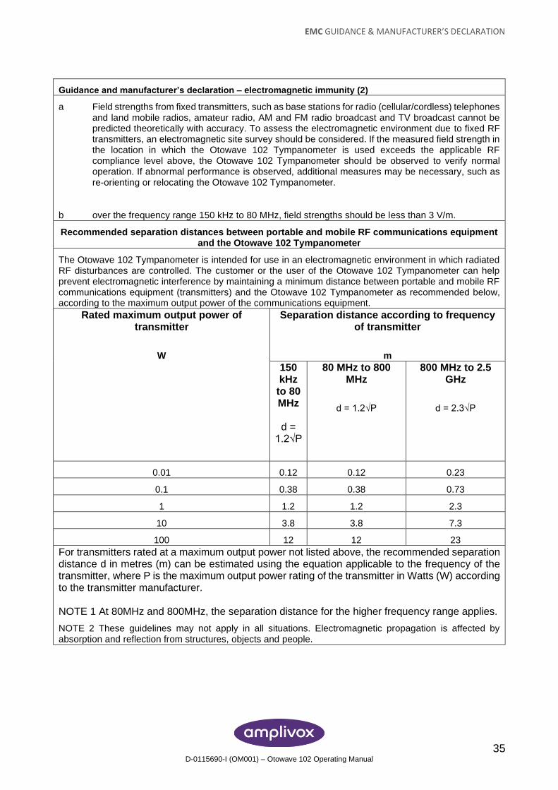
Guidance and manufacturer’s declaration – electromagnetic immunity (2)
a Field strengths from fixed transmitters, such as base stations for radio (cellular/cordless) telephones and land mobile radios, amateur radio, AM and FM radio broadcast and TV broadcast cannot be predicted theoretically with accuracy. To assess the electromagnetic environment due to fixed RF transmitters, an electromagnetic site survey should be considered. If the measured field strength in the location in which the Otowave 102 Tympanometer is used exceeds the applicable RF compliance level above, the Otowave 102 Tympanometer should be observed to verify normal operation. If abnormal performance is observed, additional measures may be necessary, such as re-orienting or relocating the Otowave 102 Tympanometer.
b over the frequency range 150 kHz to 80 MHz, field strengths should be less than 3 V/m.
Recommended separation distances between portable and mobile RF communications equipment and the Otowave 102 Tympanometer
The Otowave 102 Tympanometer is intended for use in an electromagnetic environment in which radiated RF disturbances are controlled. The customer or the user of the Otowave 102 Tympanometer can help prevent electromagnetic interference by maintaining a minimum distance between portable and mobile RF communications equipment (transmitters) and the Otowave 102 Tympanometer as recommended below, according to the maximum output power of the communications equipment.
Rated maximum output power of transmitter
W
Separation distance according to frequency of transmitter
m
150 kHz
to 80 MHz
d =
1.2√P
80 MHz to 800 MHz
d = 1.2√P
800 MHz to 2.5 GHz
d = 2.3√P
0.01 0.12 0.12 0.23
0.1 0.38 0.38 0.73
1 1.2 1.2 2.3
10 3.8 3.8 7.3
100 12 12 23
For transmitters rated at a maximum output power not listed above, the recommended separation distance d in metres (m) can be estimated using the equation applicable to the frequency of the transmitter, where P is the maximum output power rating of the transmitter in Watts (W) according to the transmitter manufacturer. NOTE 1 At 80MHz and 800MHz, the separation distance for the higher frequency range applies.
NOTE 2 These guidelines may not apply in all situations. Electromagnetic propagation is affected by absorption and reflection from structures, objects and people.
USE WITH NON-MEDICAL ELECTRICAL EQUIPMENT
36 D-0115690-I (OM001) – Otowave 102 Operating Manual
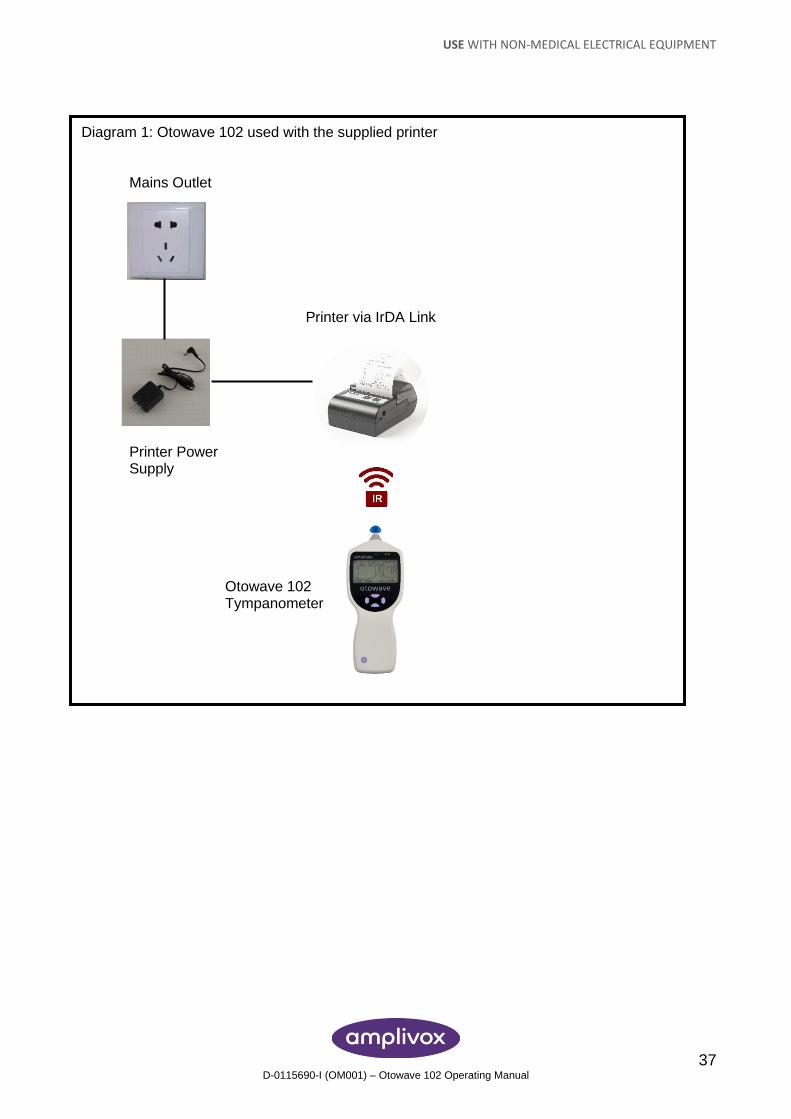
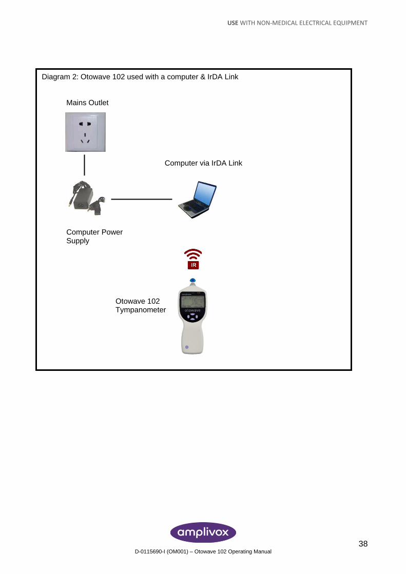
19. USE WITH NON-MEDICAL ELECTRICAL EQUIPMENT Any person who connects external equipment to signal input, signal output or other connectors has created a medical electrical system and is therefore responsible for the system complying with the requirements of clause 16 of IEC 60601-1:2005 (General requirements for basic safety and essential performance). If connections are made to standard equipment such as printers and computers, special precautions must be taken in order to maintain medical safety. The following notes are provided for guidance in making such connections to ensure that the general requirements of clause 16 of IEC 60601-1:2005 are met. The Otowave 102 tympanometer uses an industry-standard infra-red means of communication (an IrDA port) in order to reduce any potential hazard associated with the use of mains-powered equipment connecting to this interface. External equipment intended for connection to signal input, signal output or other connectors, shall comply with the relevant IEC or international standards (e.g. IEC 60950, CISPR 22 & CISPR 24 for IT equipment, and the IEC 60601 series for medical electrical equipment). Equipment not complying with IEC 60601 shall be kept outside the patient environment, as defined in IEC 60601-1:2005 (at least 1.5m from the patient). The operator must not touch the connected equipment and the patient at the same time as this would result in an unacceptable hazard. Refer to Diagrams 1 & 2 below for typical configurations of connected peripheral equipment. Refer to Amplivox Limited at the address given on the front of this user manual if advice is required regarding the use of peripheral equipment.
USE WITH NON-MEDICAL ELECTRICAL EQUIPMENT
37 D-0115690-I (OM001) – Otowave 102 Operating Manual
Diagram 1: Otowave 102 used with the supplied printer Mains Outlet
Printer via IrDA Link
Printer Power
Supply Otowave 102 Tympanometer
USE WITH NON-MEDICAL ELECTRICAL EQUIPMENT
38 D-0115690-I (OM001) – Otowave 102 Operating Manual
Diagram 2: Otowave 102 used with a computer & IrDA Link Mains Outlet
Computer via IrDA Link
Computer Power
Supply Otowave 102 Tympanometer

USE WITH NON-MEDICAL ELECTRICAL EQUIPMENT
39 D-0115690-I (OM001) – Otowave 102 Operating Manual
Copyright © 2020 Amplivox Ltd.
All rights reserved. No part of this publication may be reproduced or transmitted in any form or by any means without the prior written permission of Amplivox Ltd.