Embed Size (px)
Citation preview
1
Outdoor switches for railway lines
single- and double-pole design rated voltage up to 29 kV rated current up to 2000 A
2
General
These outdoor switches are specially designed for railway applications. They meet the specifications according to the EN 50152-2.
The live parts are in silver-plated copper with galvanization. All steel parts are hot galvanized. Upon special request an additional coating of paint (RAL 7033) is available. There is increased resistance against corrosion through the use of non-rusting materials and surface protective coating.
Each switchgear is fitted with an earth connector screw. Optionally a fixed earthing switch can be mounted.
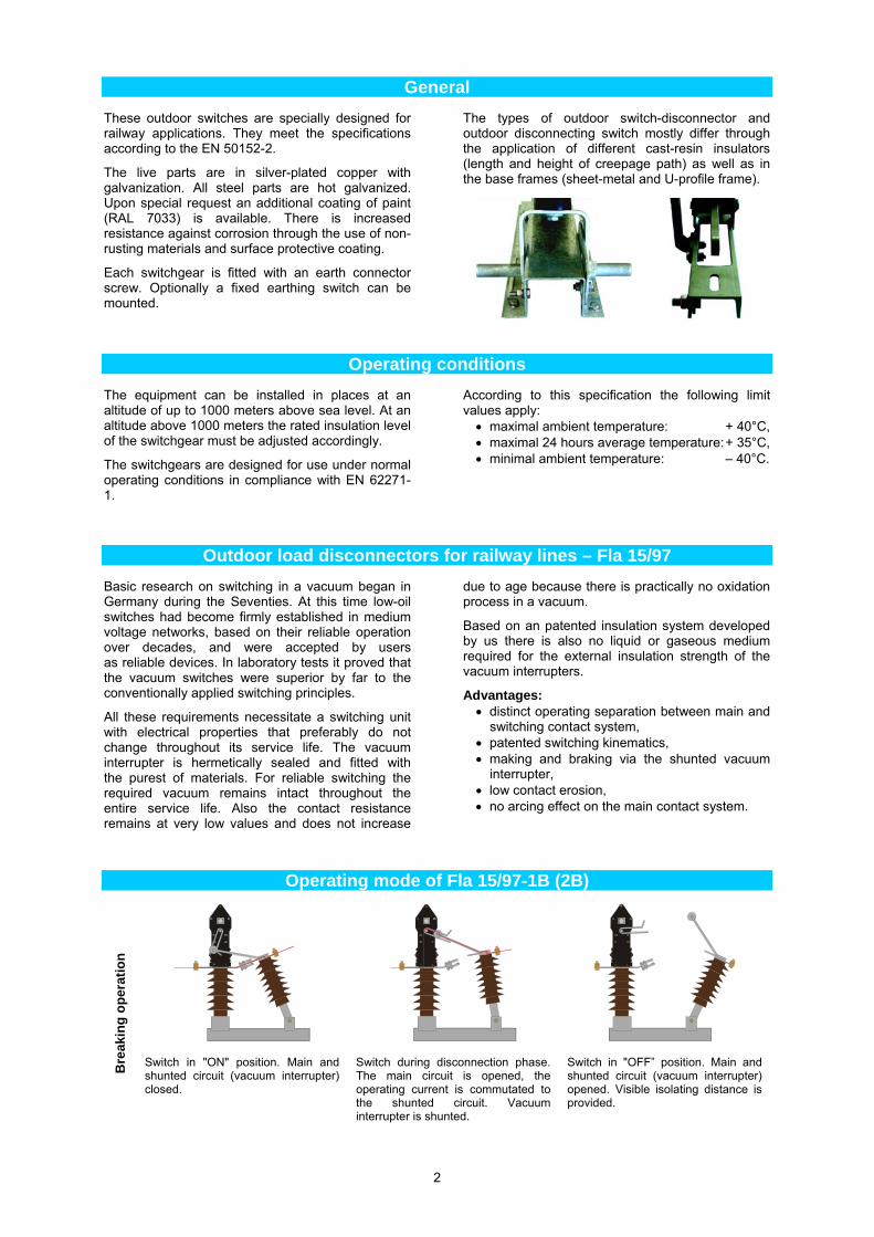
The types of outdoor switch-disconnector and outdoor disconnecting switch mostly differ through the application of different cast-resin insulators (length and height of creepage path) as well as in the base frames (sheet-metal and U-profile frame).
Operating conditions
The equipment can be installed in places at an altitude of up to 1000 meters above sea level. At an altitude above 1000 meters the rated insulation level of the switchgear must be adjusted accordingly.
The switchgears are designed for use under normal operating conditions in compliance with EN 62271-1.
According to this specification the following limit values apply: maximal ambient temperature: + 40°C, maximal 24 hours average temperature: + 35°C, minimal ambient temperature: – 40°C.
Outdoor load disconnectors for railway lines – Fla 15/97
Basic research on switching in a vacuum began in Germany during the Seventies. At this time low-oil switches had become firmly established in medium voltage networks, based on their reliable operation over decades, and were accepted by users as reliable devices. In laboratory tests it proved that the vacuum switches were superior by far to the conventionally applied switching principles.
All these requirements necessitate a switching unit with electrical properties that preferably do not change throughout its service life. The vacuum interrupter is hermetically sealed and fitted with the purest of materials. For reliable switching the required vacuum remains intact throughout the entire service life. Also the contact resistance remains at very low values and does not increase
due to age because there is practically no oxidation process in a vacuum.
Based on an patented insulation system developed by us there is also no liquid or gaseous medium required for the external insulation strength of the vacuum interrupters.
Advantages: distinct operating separation between main and
switching contact system, patented switching kinematics, making and braking via the shunted vacuum
interrupter, low contact erosion, no arcing effect on the main contact system.
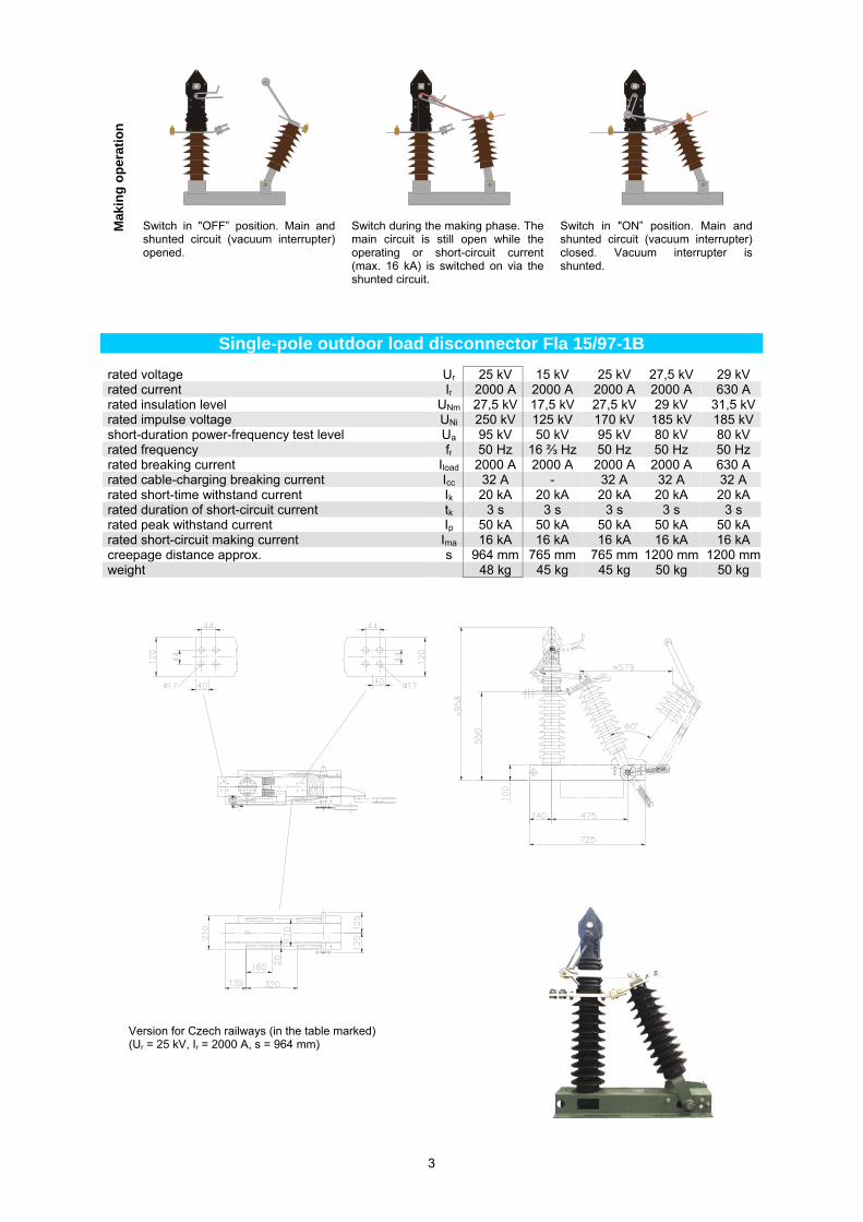
Operating mode of Fla 15/97-1B (2B)
Bre
akin
g o
per
atio
n
Switch in "ON" position. Main and shunted circuit (vacuum interrupter) closed.
Switch during disconnection phase. The main circuit is opened, the operating current is commutated to the shunted circuit. Vacuum interrupter is shunted.
Switch in "OFF” position. Main and shunted circuit (vacuum interrupter) opened. Visible isolating distance is provided.
3
Mak
ing
op
erat
ion
Switch in "OFF” position. Main and shunted circuit (vacuum interrupter) opened.
Switch during the making phase. The main circuit is still open while the operating or short-circuit current (max. 16 kA) is switched on via the shunted circuit.
Switch in "ON” position. Main and shunted circuit (vacuum interrupter) closed. Vacuum interrupter is shunted.
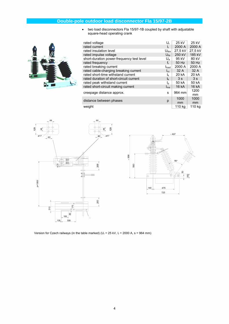
Single-pole outdoor load disconnector Fla 15/97-1B
rated voltage Ur 25 kV 15 kV 25 kV 27,5 kV 29 kV rated current Ir 2000 A 2000 A 2000 A 2000 A 630 A rated insulation level UNm 27,5 kV 17,5 kV 27,5 kV 29 kV 31,5 kVrated impulse voltage UNi 250 kV 125 kV 170 kV 185 kV 185 kVshort-duration power-frequency test level Ua 95 kV 50 kV 95 kV 80 kV 80 kV rated frequency fr 50 Hz 16 ⅔ Hz 50 Hz 50 Hz 50 Hz rated breaking current Iload 2000 A 2000 A 2000 A 2000 A 630 A rated cable-charging breaking current Icc 32 A - 32 A 32 A 32 A rated short-time withstand current Ik 20 kA 20 kA 20 kA 20 kA 20 kA rated duration of short-circuit current tk 3 s 3 s 3 s 3 s 3 s rated peak withstand current Ip 50 kA 50 kA 50 kA 50 kA 50 kA rated short-circuit making current Ima 16 kA 16 kA 16 kA 16 kA 16 kA creepage distance approx. s 964 mm 765 mm 765 mm 1200 mm 1200 mmweight 48 kg 45 kg 45 kg 50 kg 50 kg
Version for Czech railways (in the table marked) (Ur = 25 kV, Ir = 2000 A, s = 964 mm)
4
Double-pole outdoor load disconnector Fla 15/97-2B
two load disconnectors Fla 15/97-1B coupled by shaft with adjustable square-head operating crank
rated voltage Ur 25 kV 25 kV rated current Ir 2000 A 2000 Arated insulation level UNm 27,5 kV 27,5 kVrated impulse voltage UNi 250 kV 185 kVshort-duration power-frequency test level Ua 95 kV 80 kV rated frequency fr 50 Hz 50 Hz rated breaking current Iload 2000 A 2000 Arated cable-charging breaking current Icc 32 A 32 A rated short-time withstand current Ik 20 kA 20 kA rated duration of short-circuit current tk 3 s 3 s rated peak withstand current Ip 50 kA 50 kA rated short-circuit making current Ima 16 kA 16 kA
creepage distance approx. s 964 mm 1200 mm
distance between phases p 1000 mm
1000 mm
weight 110 kg 110 kg
Version for Czech railways (in the table marked) (Ur = 25 kV, Ir = 2000 A, s = 964 mm)
5
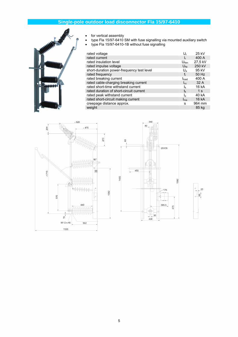
Single-pole outdoor load disconnector Fla 15/97-6410
for vertical assembly type Fla 15/97-6410 SM with fuse signalling via mounted auxiliary switch type Fla 15/97-6410-1B without fuse signalling
rated voltage Ur 25 kV rated current Ir 400 A rated insulation level UNm 27,5 kV rated impulse voltage UNi 250 kV short-duration power-frequency test level Ua 95 kV rated frequency fr 50 Hz rated breaking current Iload 400 A rated cable-charging breaking current Icc 32 A rated short-time withstand current Ik 16 kA rated duration of short-circuit current tk 1 s rated peak withstand current Ip 40 kA rated short-circuit making current Ima 16 kA creepage distance approx. s 964 mm weight 85 kg
6
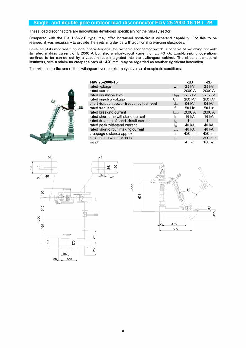
Single- and double-pole outdoor load disconnector FlaV 25-2000-16-1B / -2B
These load disconnectors are innovations developed specifically for the railway sector.
Compared with the Fla 15/97-1B type, they offer increased short-circuit withstand capability. For this to be realised, it was necessary to provide the switching device with additional pre-arcing electrodes.
Because of its modified functional characteristics, the switch-disconnector switch is capable of switching not only its rated making current of Ir 2000 A but also a short-circuit current of Ima 40 kA. Load-breaking operations continue to be carried out by a vacuum tube integrated into the switchgear cabinet. The silicone compound insulators, with a minimum creepage path of 1420 mm, may be regarded as another significant innovation.
This will ensure the use of the switchgear even in extremely adverse atmospheric conditions.
FlaV 25-2000-16 -1B -2Brated voltage Ur 25 kV 25 kV rated current Ir 2000 A 2000 A rated insulation level UNm 27,5 kV 27,5 kV rated impulse voltage UNi 250 kV 250 kV short-duration power-frequency test level Ua 95 kV 95 kV rated frequency fr 50 Hz 50 Hz rated breaking current Iload 2000 A 2000 A rated short-time withstand current Ik 16 kA 16 kA rated duration of short-circuit current tk 1 s 1 s rated peak withstand current Ip 40 kA 40 kA rated short-circuit making current Ima 40 kA 40 kA creepage distance approx. s 1420 mm 1420 mmdistance between phases p - 1290 mmweight 45 kg 100 kg
7
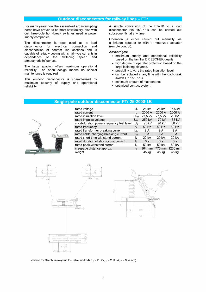
Outdoor disconnectors for railway lines – FTr
For many years now the assembled arc interrupting horns have proven to be most satisfactory, also with our three-pole horn-break switches used in power supply companies.
The disconnector is also used as a load disconnector for electrical connection and disconnection of contact line sections and is capable of reliably coping with small-type currents in dependence of the switching speed and atmospheric influences.
The large spacing offers maximum operational reliability. The open design means no special maintenance is required.
This outdoor disconnector is characterized by maximum security of supply and operational reliability.
A simple conversion of the FTr-1B to a load disconnector Fla 15/97-1B can be carried out subsequently, at any time.
Operation is either carried out manually via a linkage actuator or with a motorized actuator (remote control).
Advantages: maximum supply and operational reliability
based on the familiar DRIESCHER quality, high degree of operator protection based on the
large isolating distance, possibility to vary the rated insulation level, can be replaced at any time with the load-break
switch Fla 15/97-1B, minimum amount of maintenance, optimised contact system.
Single-pole outdoor disconnector FTr 25-2000-1B
rated voltage Ur 25 kV 25 kV 27,5 kVrated current Ir 2000 A 2000 A 2000 A rated insulation level UNm 27,5 kV 27,5 kV 29 kV rated impulse voltage UNi 250 kV 170 kV 185 kV short-duration power-frequency test level Ua 95 kV 90 kV 80 kV rated frequency fr 50 Hz 50 Hz 50 Hz rated transformer breaking current Inltr 9 A 9 A 9 A rated cable-charging breaking current Icc 6 A 6 A 6 A rated short-time withstand current Ik 20 kA 20 kA 20 kA rated duration of short-circuit current tk 3 s 3 s 3 s rated peak withstand current Ip 50 kA 50 kA 50 kA creepage distance approx. s 964 mm 775 mm 1200 mmweight 45 kg 45 kg 45 kg
Version for Czech railways (in the table marked) (Ur = 25 kV, Ir = 2000 A, s = 964 mm)
8
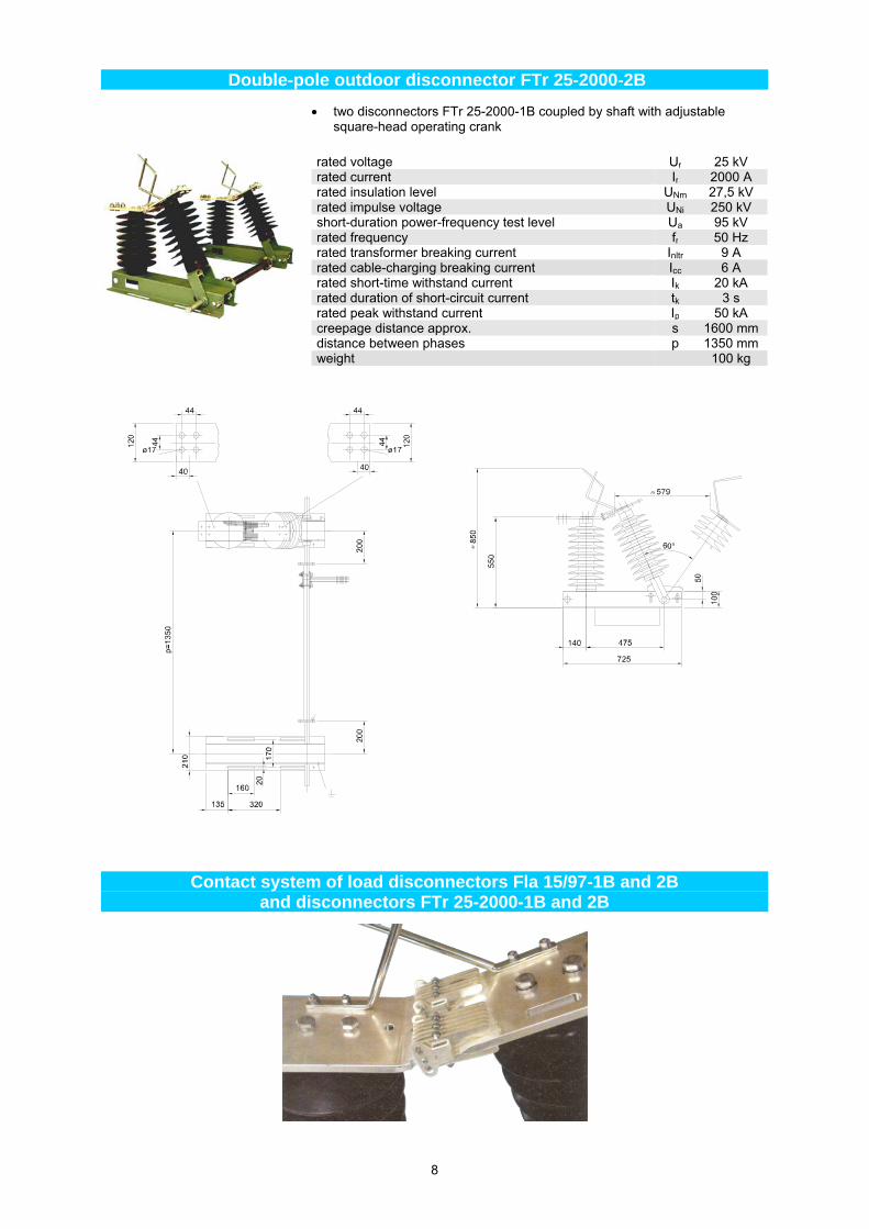
Double-pole outdoor disconnector FTr 25-2000-2B
two disconnectors FTr 25-2000-1B coupled by shaft with adjustable square-head operating crank
rated voltage Ur 25 kV rated current Ir 2000 A rated insulation level UNm 27,5 kV rated impulse voltage UNi 250 kV short-duration power-frequency test level Ua 95 kV rated frequency fr 50 Hz rated transformer breaking current Inltr 9 A rated cable-charging breaking current Icc 6 A rated short-time withstand current Ik 20 kA rated duration of short-circuit current tk 3 s rated peak withstand current Ip 50 kA creepage distance approx. s 1600 mm distance between phases p 1350 mm weight 100 kg
Contact system of load disconnectors Fla 15/97-1B and 2B and disconnectors FTr 25-2000-1B and 2B
9
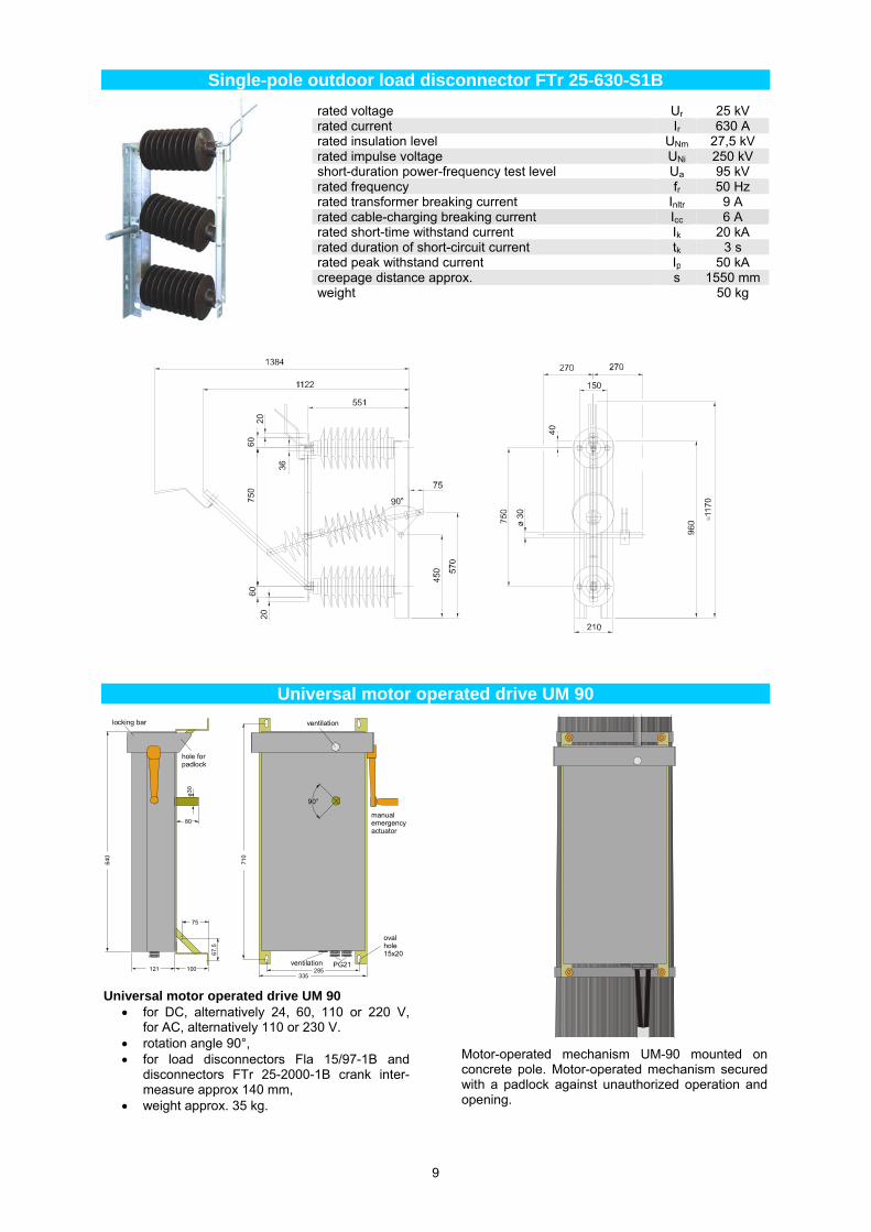
Single-pole outdoor load disconnector FTr 25-630-S1B
rated voltage Ur 25 kV rated current Ir 630 A rated insulation level UNm 27,5 kV rated impulse voltage UNi 250 kV short-duration power-frequency test level Ua 95 kV rated frequency fr 50 Hz rated transformer breaking current Inltr 9 A rated cable-charging breaking current Icc 6 A rated short-time withstand current Ik 20 kA rated duration of short-circuit current tk 3 s rated peak withstand current Ip 50 kA creepage distance approx. s 1550 mm weight 50 kg
Universal motor operated drive UM 90
121 100
75
67,
5
ø3
0
80
640
90°
285PG21
ovalhole 15x20
ventilation
manualemergencyactuator
335
710
hole forpadlock
locking bar
ventilation
Universal motor operated drive UM 90 for DC, alternatively 24, 60, 110 or 220 V,
for AC, alternatively 110 or 230 V. rotation angle 90°, for load disconnectors Fla 15/97-1B and
disconnectors FTr 25-2000-1B crank inter-measure approx 140 mm,
weight approx. 35 kg.
Motor-operated mechanism UM-90 mounted on concrete pole. Motor-operated mechanism secured with a padlock against unauthorized operation and opening.
10
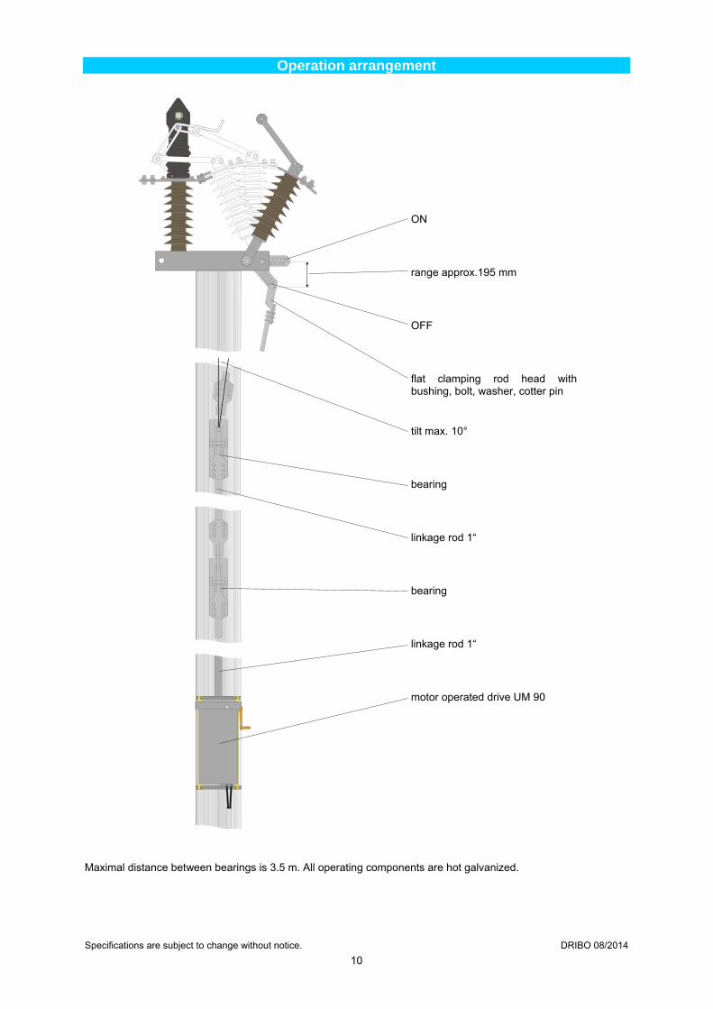
Operation arrangement
Maximal distance between bearings is 3.5 m. All operating components are hot galvanized. Specifications are subject to change without notice. DRIBO 08/2014
ON
range approx.195 mm
OFF
flat clamping rod head with bushing, bolt, washer, cotter pin
tilt max. 10°
bearing
linkage rod 1“
bearing
linkage rod 1“
motor operated drive UM 90