Embed Size (px)
Citation preview

Over viewOver view
Landing GearLanding Gear Weight DeterminationWeight Determination Geometric Layout of Wing StructureGeometric Layout of Wing Structure Analysis of Wing LoadsAnalysis of Wing Loads Fuselage and Tail StructureFuselage and Tail Structure
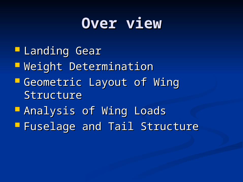
Landing GearLanding Gear Front Landing GearFront Landing Gear Material: carbon fiberMaterial: carbon fiber 8" wide, 5" tall,1-5/8" 8" wide, 5" tall,1-5/8"
wide at top, 1" at wide at top, 1" at bottom, 1.5 oz. weight. bottom, 1.5 oz. weight.
Main WheelMain Wheel Diameter: 2-1/16" Diameter: 2-1/16" Steerable Tail Landing Steerable Tail Landing
GearGear 2-3/4" x 3" with 7/8" 2-3/4" x 3" with 7/8"
Plain Plain WheelWheel
Landing Gear AnalysisLanding Gear Analysis
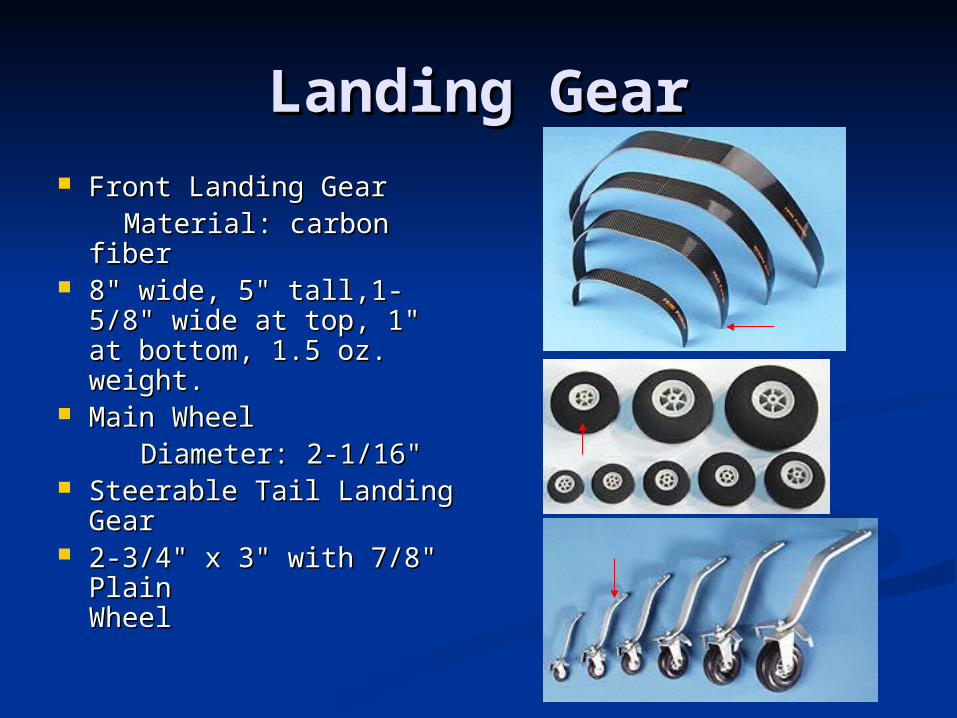
Assumptions: Assumptions:
1.1. Main Landing Wheels support 90% of Main Landing Wheels support 90% of weights.weights.
2.2. Taildragger aft tires are about a Taildragger aft tires are about a quarter to a third the size of the main quarter to a third the size of the main tires. tires.
Tire sizing:Tire sizing:
Diameter : 1.96 inDiameter : 1.96 in
Width: 0.9 inWidth: 0.9 in
0.312 B
0.715 A
Width
0.349 B
1.51 A
Diameter
wheelon theweight W
WAor WD
W
BWmainmain
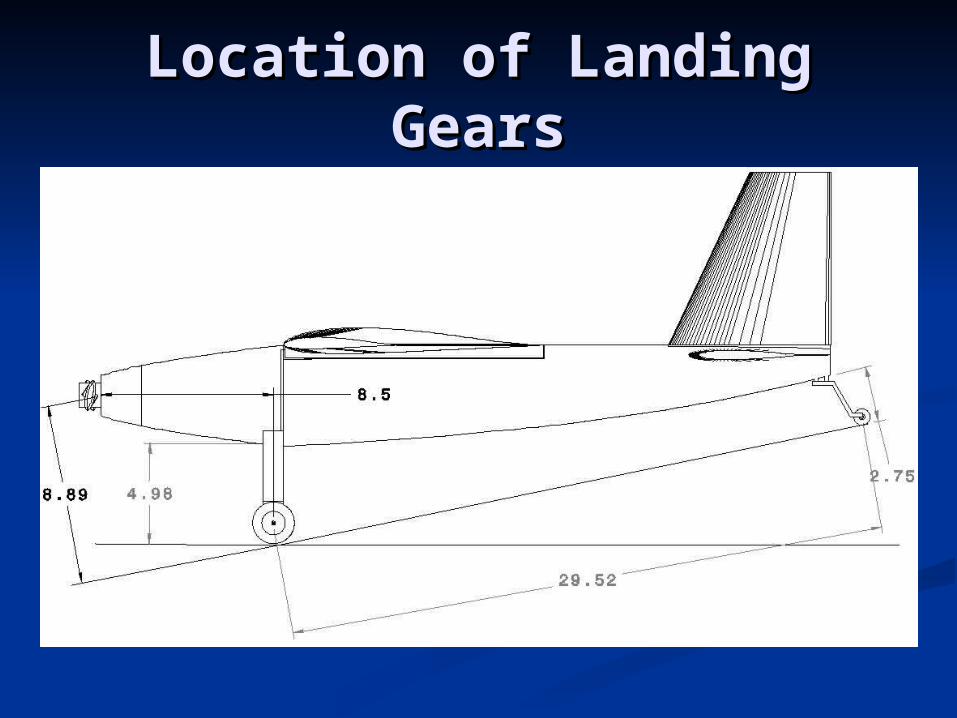
Location of Landing Location of Landing GearsGears
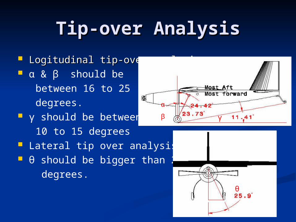
Tip-over AnalysisTip-over Analysis Logitudinal tip-over analysisLogitudinal tip-over analysis α & β should be between 16 to 25 degrees. γ should be between 10 to 15 degrees Lateral tip over analysis. θ should be bigger than 25 degrees.
α
β γ
θ
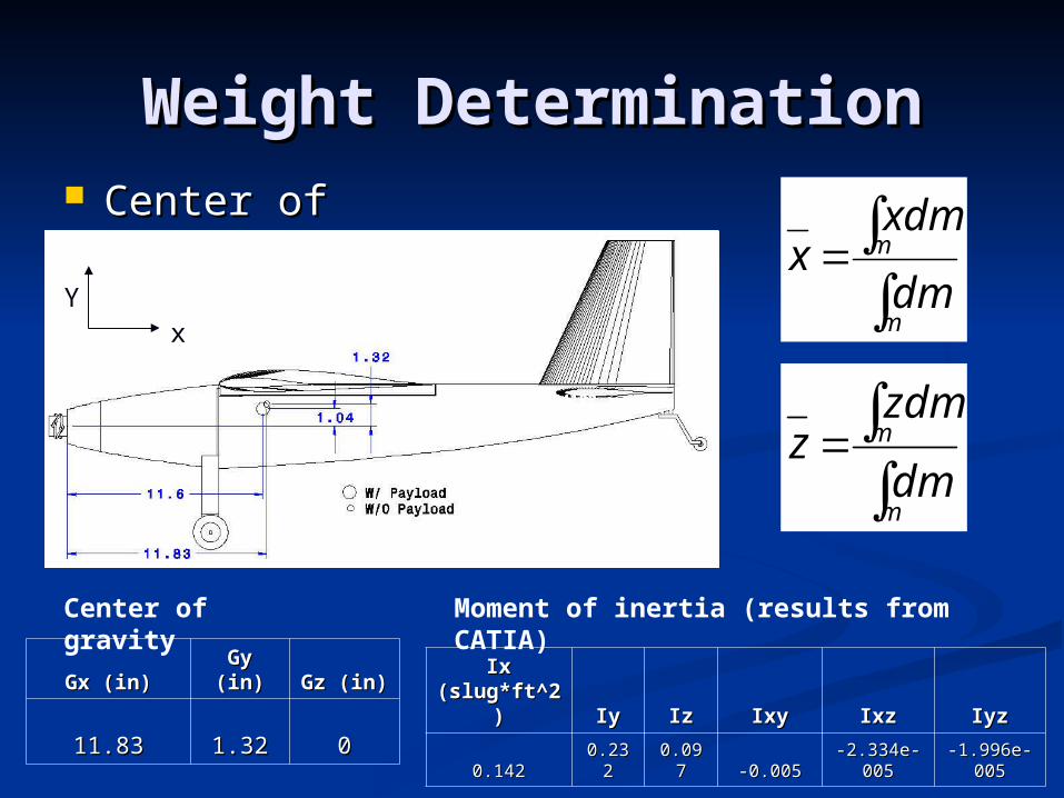
Weight DeterminationWeight Determination Center of gravityCenter of gravity
m
m
dm
xdmx
m
m
dm
zdmz
Center of gravity Moment of inertia (results from CATIA)
Gx (in)Gx (in)Gy Gy (in)(in) Gz (in)Gz (in)
11.8311.83 1.321.32 00
Ix Ix (slug*ft^2(slug*ft^2
)) IyIy IzIz IxyIxy IxzIxz IyzIyz
0.1420.142 0.2320.232 0.0970.097 -0.005-0.005-2.334e--2.334e-
005005-1.996e--1.996e-
005005
11.6582418211.65824182
xY

List of ComponentsList of Componentscomponent material weight (lb)
internal body balsawood + foam 0.1444
main wing foam + fiber glass 1.2750
vertical wing foam + fiber glass 0.0946
horizontal stabilizer foam + fiber glass 0.2214
fuselage foam 0.1935
wing Mount balsawood + foam 0.0181
nose cap fiber glass 0.0773
motor (w/ gear box) 0.8000
gyro 0.0400
servo (rudder,elevator,flaperon) 0.3791
receiver 0.0397
speed control 0.1000
battery 0.5000
landing gear 0.1243
payload 1.0000
total (including battery payload) 5.0074
(excluding battery and payload) 3.5074
Total Weight:
5.0074 lb
(excluding control wire, hinge and glue)

Layout of ComponentsLayout of Components
Motor Battery
Payload
Speed controller
GyroReceiver
Servos
(Rudder
Elevator)

Material Properties of Wing Material Properties of Wing StructureStructure
Material Material PropertiesProperties
E-GlassE-Glass
Density (lb/in^3)Density (lb/in^3) 0.0940.094
Tensile Strength (psi)Tensile Strength (psi)493128.32493128.32
99
Tensile Modulus (Psi)Tensile Modulus (Psi)10500732.10500732.
658658
Elongation to break (%)Elongation to break (%) 4.8004.800
EpoxyEpoxy
Tensile Strength (Psi)Tensile Strength (Psi) 11008.36511008.365
% Elongation% Elongation 6.3006.300
Flexural Strength (Psi)Flexural Strength (Psi) 16708.34816708.348
Flexural Modulus (Psi)Flexural Modulus (Psi)464120.78464120.78
00
Short Beam Shear (Psi)Short Beam Shear (Psi) 8006.0838006.083
Density (lb/in^3)Density (lb/in^3) 0.0419080.041908
Balsa woodBalsa wood
Density (lb/in^3)Density (lb/in^3) 0.0050.005
Modules of rupture (Psi)Modules of rupture (Psi) 31403140
maximum shearing maximum shearing strength (Psi)strength (Psi) 300300
Compression Strength Compression Strength (Psi)(Psi) 18901890
Density of CompositeDensity of Composite 50% Epoxy + 50% E-Glass50% Epoxy + 50% E-Glass
Density of Balsa woodDensity of Balsa wood 0.005 (lb/in^3)0.005 (lb/in^3)
Density of foamDensity of foam 0.0011(lb/in^3)0.0011(lb/in^3)
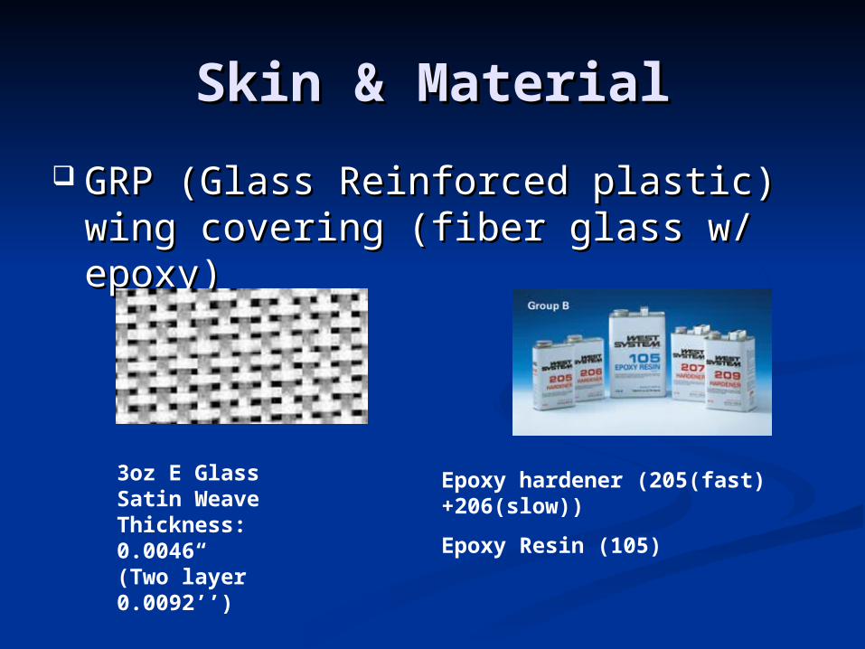
Skin & MaterialSkin & Material
GRP (Glass Reinforced plastic) wing GRP (Glass Reinforced plastic) wing covering (fiber glass w/ epoxy)covering (fiber glass w/ epoxy)
3oz E Glass Satin WeaveThickness: 0.0046“(Two layer 0.0092’’)
Epoxy hardener (205(fast) +206(slow))
Epoxy Resin (105)
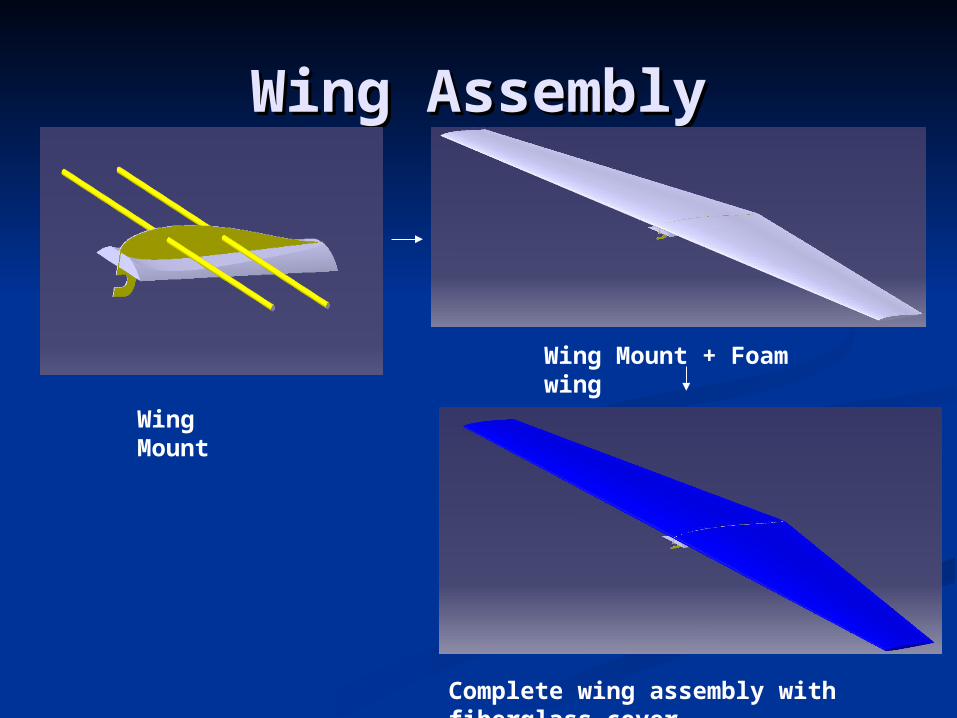
Wing AssemblyWing Assembly
Wing Mount
Wing Mount + Foam wing
Complete wing assembly with fiberglass cover
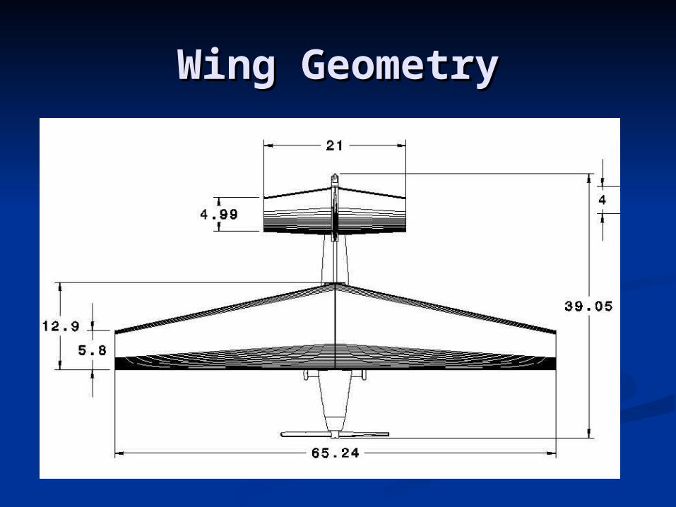
Wing GeometryWing Geometry
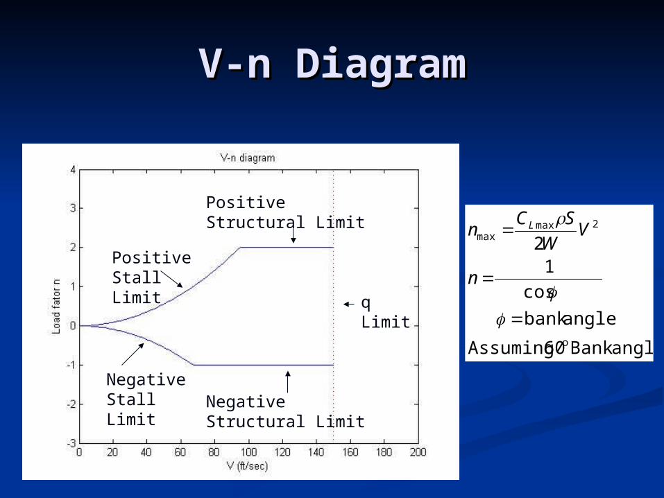
V-n DiagramV-n Diagram
angleBank 60 Assuming
anglebank
cos
12
o
2maxmax
n
VW
SCn L
Positive Stall Limit
Negative Stall Limit
Positive Structural Limit
Negative Structural Limit
q Limit
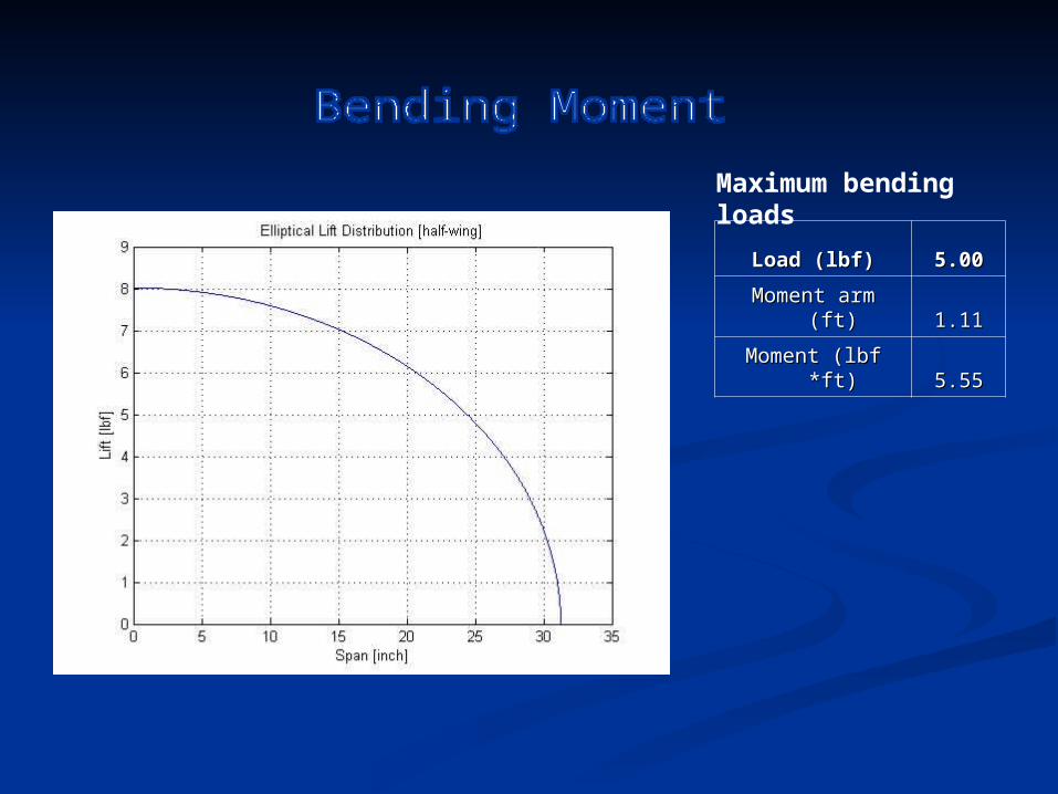
Load (lbf)Load (lbf) 5.005.00
Moment arm (ft)Moment arm (ft) 1.111.11
Moment (lbf *ft)Moment (lbf *ft) 5.555.55
Maximum bending loads

Bending Moment StudyBending Moment Study
(psi) 210000
glassfiber
ofstrength Tensile
(psi) 34983x
x I
My
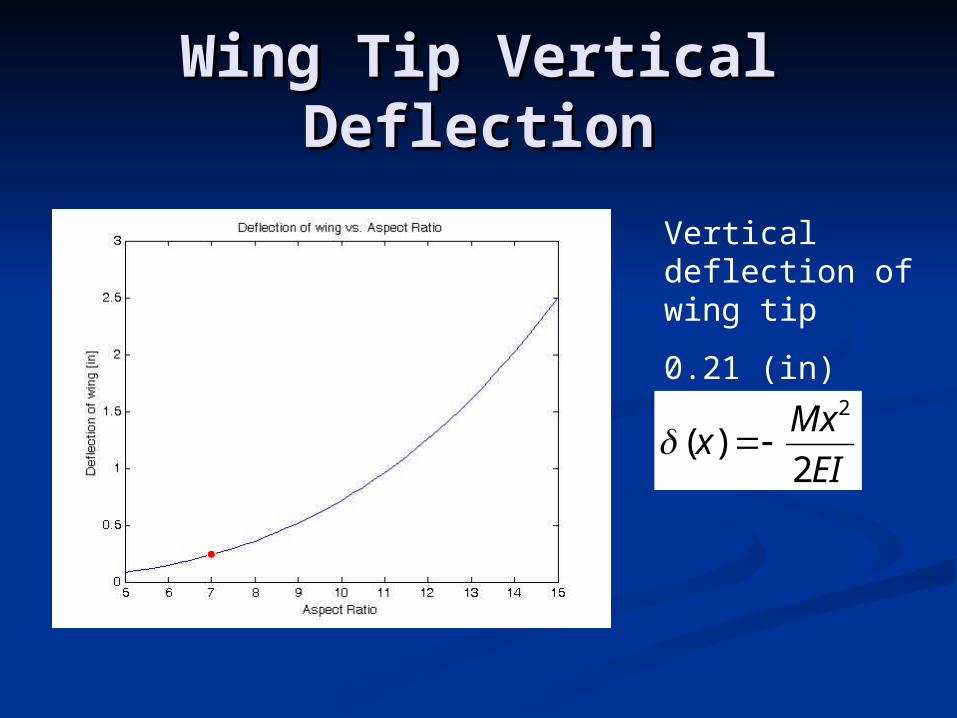
Wing Tip Vertical Wing Tip Vertical DeflectionDeflection
Vertical deflection of wing tip
0.21 (in)
EI
Mxx
2)(
2
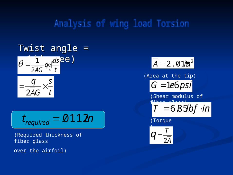
Twist angle = Twist angle = 1(degree)1(degree)
22.015inA
t
dsq
GA2
1
psieG 61
inlbfT 85.6
(Shear modulus of fiber glass)
(Required thickness of fiber glass
over the airfoil)
t
s
GA
q
2
A
Tq2
intrequired 0112.
(Area at the tip)
(Torque)

Skin Materials Trade Skin Materials Trade StudyStudy
Purpose: To compare weight of skin made of different materials
Method: Single cell Thin-walled analysis
Result: Fiber glass has lowest weight
Foam Balsa WoodFiber
Glass
Shear Modulus 550 23600 1000000 Psi
Density 1.87 9.68 117.41 lb/ft^3
Required Skin Thickness
38.8970 0.8209 0.0194 in
Volume13.719
7 0.2895 0.0068 ft^3
Mass25.694
4 2.8017 0.8037 lb
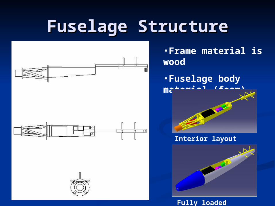
Fuselage StructureFuselage Structure•Frame material is wood
•Fuselage body material (foam)
Interior layout
Fully loaded fuselage
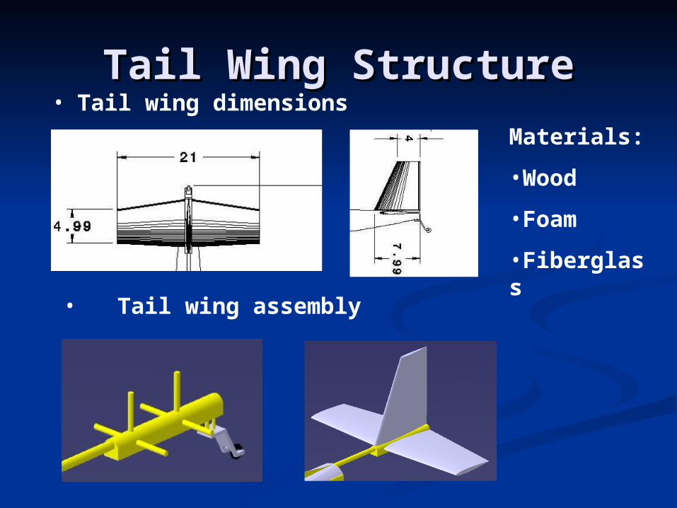
Tail Wing StructureTail Wing Structure• Tail wing dimensions
• Tail wing assembly
Materials:
•Wood
•Foam
•Fiberglass

Questions ?


![Vertical Takeoff and Landing Wing Developed for Long ...the weight of the entire airframe (6.43 kg), and could be lifted at an airframe speed of 15m/s [8]. Figure 6. Wing design using](https://img.pdfslide.net/doc/110x75/611e95bf93ba6f39ca484db2/vertical-takeoff-and-landing-wing-developed-for-long-the-weight-of-the-entire.jpg)