Embed Size (px)
Citation preview

Application Report SLLA337 – January 2013
1
Overview of 3.3V CAN (Controller Area Network) Transceivers
Jason Blackman and Scott Monroe
ABSTRACT
3.3V CAN (Controller Area Network) transceivers offer advantages and flexibility with respect to 5V CAN transceivers while being compatible and interoperable with each other. Power consumption is lower with 3.3V transceiver compared with 5V transceivers. There is potential for power supply simplification and cost savings when the microprocessor communicating with the transceiver is also at 3.3V.
Some implementers of CAN buses may be skeptical to use 3.3V transceivers due to the legacy of 5V transceivers that are known to perform well. There may be uncertainty of performance in mixed supply CAN buses. This application note demonstrates the interoperability of 3.3V and 5V CAN transceivers in addition to explaining the theory of operation.
Contents 1 THEORY OF OPERATION ............................................................................................................ 2
2 MEASUREMENTS DEMONSTRATING OPERATION ................................................................... 4
3 CONFORMANCE TESTING .......................................................................................................... 9
4 3.3V DEVICE ADVANTAGES ...................................................................................................... 10
5 SUMMARY ................................................................................................................................... 11

SLLA337
2 Overview of 3.3V CAN (Controller Area Network) Transceivers
1 THEORY OF OPERATION
The ISO 11898 specification details the physical layer requirements for CAN bus communications. CAN is a low-level communication protocol over a twisted pair cable, similar to RS-485.
Figure 1. Typical CAN Network
An important feature of CAN is that the bus isn’t actively driven during logic ‘High’ transmission, referred to as ‘recessive.’ During this time, both bus lines are typically at the same voltage, approximately VCC/2. The bus is only driven during ‘dominant’ transmission, or during logic ‘Low.’ In Dominant, the bus lines are driven such that (CANH – CANL) ≥ 1.5V. This allows a node transmitting a ‘High’ to detect if another node is trying to send a ‘Low’ at the same time. This is used for non-destructive arbitration, where nodes start each message with an address (priority code) to determine which node will get to use the bus. The node with the lowest binary address wins arbitration and continues with its message. There is no need to back-off and retransmit like other protocols.
CAN receivers measure differential voltage on the bus to determine the bus level. Since 3.3V transceivers generate the same differential voltage (≥1.5V) as 5V transceivers, all transceivers on the bus (regardless of supply voltage) can decipher the message. In fact, the other transceivers can’t even tell there is anything different about the differential voltage levels.

SLLA337
Overview of 3.3V CAN (Controller Area Network) Transceivers 3
RecessiveLogic H
DominantLogic L
RecessiveLogic H
Time, t
Typi
cal B
us V
olta
ge (V
)
CANL
CANH
Vdiff(D)
Vdiff(R)
12
34
5V CAN
RecessiveLogic H
DominantLogic L
RecessiveLogic H
Time, t
Typi
cal B
us V
olta
ge (V
)
CANL
CANH
Vdiff(D)
Vdiff(R)
12
34
3.3V CAN
Figure 2. Typical CAN Bus Levels for 5V and 3.3V Transceivers
Figure 2 (above) shows bus voltages for 5V transceivers as well as 3.3V transceivers. For 5V CAN, CANH and CANL are weakly biased at about 2.5V (VCC/2) during recessive. The recessive common-mode voltage for 3.3V CAN is biased higher than VCC/2, typically about 2.3V. This is done to better match the common mode point of the 5V CAN transceivers and minimize the common mode changes on the bus between 3.3V and 5V transceivers. Since CAN was defined as a differential bus with wide common mode allowing for ground shifts (DC offsets between nodes) this isn’t needed for operation, but will minimize emissions in a mixed network. In addition, by using split termination to filter the common mode of the network a significant reduction in emissions is possible. The ISO 11898-2 standard states that transceivers must operate with a common-mode range of -2V to 7V, so the typical 0.2V common-mode shift between 3.3V and 5V transceivers doesn’t pose a problem.

SLLA337
4 Overview of 3.3V CAN (Controller Area Network) Transceivers
2 MEASUREMENTS DEMONSTRATING OPERATION
Figure 3. Waveforms of Two 5V SN65HVD255 Transceivers
Figure 3 (above) shows two 5V transceivers communicating on the same bus. In this case, transceiver (XCVR) 1 and 2 are both Texas Instruments’ SN65HVD255 CAN transceiver. The signals ‘TXD1’ and ‘TXD2’ show what each transceiver is driving onto the bus, while ‘RXD1’ and ‘RXD2’ show what each transceiver is reading from the bus. The two upper signals are the bus lines, CANH (yellow) and CANL (light blue). The red waveform below them is the calculated differential voltage between CANH and CANL.
A simplified bit pattern was used to demonstrate CAN bus principles. Bit time 1: one transceiver transmits a dominant bit while the other remains recessive. Bit time 2: both transceivers are recessive. Bit time 3: both transmit dominant, showing what would happen during arbitration. As shown the differential voltage is slightly greater when both transceivers are dominant due to the output transistors of each transceiver being in parallel, resulting in a smaller voltage drop and greater differential voltage output.

SLLA337
Overview of 3.3V CAN (Controller Area Network) Transceivers 5
Figure 4 (below) shows the same setup but with two 3.3V transceivers (TI SN65HVD234). The differential voltage between the bus lines during dominant bits is lower than the 5V devices that were tested, but is still meets the requirements of the ISO 11898-2 standard. In addition, the guaranteed minimum differential bus voltage for the 5V devices is the same as with the 3.3V devices (1.5V). This means that designers have no advantage if choosing 5V devices for their higher differential driving abilities, since there is no guarantee that the differential output will be higher.
Figure 4. Waveforms of Two 3.3V SN65HVD234 Transceivers

SLLA337
6 Overview of 3.3V CAN (Controller Area Network) Transceivers
Figure 5. Waveform of Two SN65HVD255 Transceivers, One with a +1V Ground Shift
Figure 5 (above) shows how robust CAN is with common mode differences. The red Math signal shows the common mode voltage instead of differential voltage in previous plots. The bus signals become very ugly when arbitration between ground shifted transceivers occurs. However, the RXD1 signal shows that the transceivers don’t have a problem because the differential signal is good and the transceiver correctly detects the signal on the bus.
SLLA337
Overview of 3.3V CAN (Controller Area Network) Transceivers 7
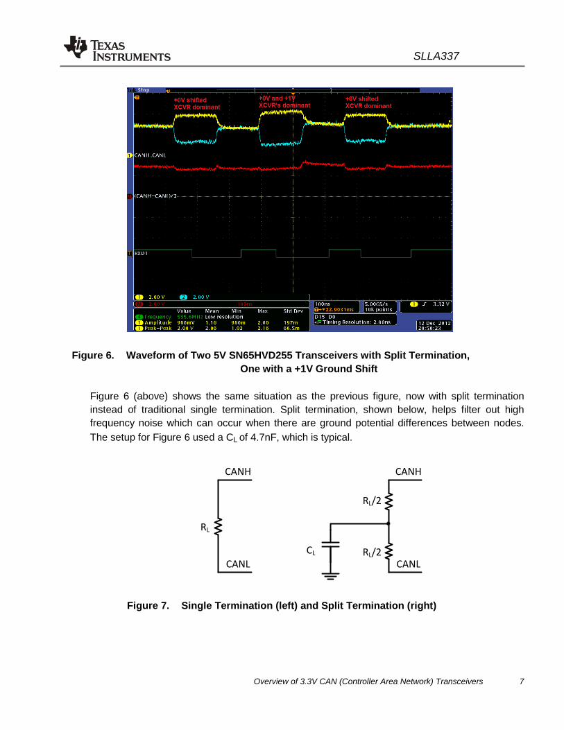
Figure 6. Waveform of Two 5V SN65HVD255 Transceivers with Split Termination, One with a +1V Ground Shift
Figure 6 (above) shows the same situation as the previous figure, now with split termination instead of traditional single termination. Split termination, shown below, helps filter out high frequency noise which can occur when there are ground potential differences between nodes. The setup for Figure 6 used a CL of 4.7nF, which is typical.
CANL
CANH
RL
CANL
CANH
RL/2
RL/2
CL
Figure 7. Single Termination (left) and Split Termination (right)

SLLA337
8 Overview of 3.3V CAN (Controller Area Network) Transceivers
Figure 8. Waveform of a 5V SN65HVD255 and a 3.3V SN65HVD234
Figure 8 (above) shows communication with a mixed network of one 3.3V transceiver and one 5V transceiver. As before, the digital signals TXD1, TXD2, RXD1 and RXD2 show that both transceivers are accurately talking to each other and there is little common mode shift during the communication in contrast to the 5V homogeneous network with a 1V ground shift.

SLLA337
Overview of 3.3V CAN (Controller Area Network) Transceivers 9
Figure 9. Bus Communication of a 5V SN65HVD1050 and a 3.3V SN65HVD230
Figure 9 (above) shows a CAN frame in a mixed network of two 3.3V transceivers and one 5V transceiver to demonstrate these principles in a CAN frame from a functional mixed system.
3 CONFORMANCE TESTING
The TI SN65HVD23x 3.3V CAN families have been successfully tested by the internationally recognized third party communications and systems (C&S) group GmbH to the GIFT/ICT CAN High-Speed Transceiver Conformance Test. This testing covers a homogeneous network of all 3.3V transceivers and a heterogeneous network where four out of sixteen CAN nodes are the 3.3V transceiver and the remaining twelve CAN nodes are a mix of three other “golden” reference, non TI 5V CAN transceivers. Both TI 3.3V CAN transceiver families successfully passed this testing with no findings and the certificates of authentication were issued.

SLLA337
10 Overview of 3.3V CAN (Controller Area Network) Transceivers
4 3.3V DEVICE ADVANTAGES
The 3.3V transceivers tested clearly operate in mixed supply networks, so now let’s look at their advantages. The first advantage is lower power. Not only are 3.3V transceivers lower voltage, they are also lower current.
Table 1. Chart of Supply Current for Three Different Two-Node Buses
Case 1: 2X SN65HVD234 SN65HVD234 #1 ICC (mA) SN65HVD234 #1 ICC (mA)
Both recessive 7.1 7.2
#1 dominant 38.4 7.2
Both dominant 25.9 26.1
Case 2: 2X SN65HVD255 SN65HVD255#1 ICC (mA) SN65HVD255 #1 ICC (mA)
Both recessive 18.6 18.6
#1 dominant 61.8 18.4
Both dominant 44.6 44.8
Case 3: Mixed SN65HVD234 ICC (mA) SN65HVD255 ICC (mA)
Both recessive 7.2 18.6
SN65HVD234 dominant 38.6 18.6
SN65HVD255 dominant 7.2 61.8
Both dominant 11.7 58.9
Table 1 shows the supply current for 3.3V devices is reduced by nearly half. Combined with the already lower supply voltage, this results in significant power reduction.
SLLA337
Overview of 3.3V CAN (Controller Area Network) Transceivers 11
Several other advantages emerge when used with a 3.3V microcontroller. The digital I/O of a 5V transceiver would be level shifted either externally or in the 5V CAN transceiver to avoid damaging the microcontroller (unless it is 5V tolerant) where as a 3.3V transceiver could be directly connected to this microcontroller. The SN65HVD233/234/235 3.3V transceivers have 5V tolerant inputs so they may be used directly with a 3.3V or a 5V microcontroller. If 5V was only used in the system for CAN, a 3.3V CAN transceiver would eliminate the need for the 5V power supply, simplifying the power domains and lowering the cost.
5 SUMMARY
3.3V and 5V CAN transceivers are interoperable because High Speed CAN physical layer uses differential signalling that is the same for a 3.3V and 5V CAN transceiver. In addition both the 3.3V and 5V CAN transceivers have the same wide common mode range accommodating not only the typical signalling but also providing wide margin for ground shift potential. For systems that can benefit from the advantages of 3.3V transceivers, such as simplified power supplies and lower power consumption they offer clear advantages in their use either in a homogeneous 3.3V CAN network or in a mixed 3.3V and 5V CAN network.

IMPORTANT NOTICE
Texas Instruments Incorporated and its subsidiaries (TI) reserve the right to make corrections, enhancements, improvements and otherchanges to its semiconductor products and services per JESD46, latest issue, and to discontinue any product or service per JESD48, latestissue. Buyers should obtain the latest relevant information before placing orders and should verify that such information is current andcomplete. All semiconductor products (also referred to herein as “components”) are sold subject to TI’s terms and conditions of salesupplied at the time of order acknowledgment.
TI warrants performance of its components to the specifications applicable at the time of sale, in accordance with the warranty in TI’s termsand conditions of sale of semiconductor products. Testing and other quality control techniques are used to the extent TI deems necessaryto support this warranty. Except where mandated by applicable law, testing of all parameters of each component is not necessarilyperformed.
TI assumes no liability for applications assistance or the design of Buyers’ products. Buyers are responsible for their products andapplications using TI components. To minimize the risks associated with Buyers’ products and applications, Buyers should provideadequate design and operating safeguards.
TI does not warrant or represent that any license, either express or implied, is granted under any patent right, copyright, mask work right, orother intellectual property right relating to any combination, machine, or process in which TI components or services are used. Informationpublished by TI regarding third-party products or services does not constitute a license to use such products or services or a warranty orendorsement thereof. Use of such information may require a license from a third party under the patents or other intellectual property of thethird party, or a license from TI under the patents or other intellectual property of TI.
Reproduction of significant portions of TI information in TI data books or data sheets is permissible only if reproduction is without alterationand is accompanied by all associated warranties, conditions, limitations, and notices. TI is not responsible or liable for such altereddocumentation. Information of third parties may be subject to additional restrictions.
Resale of TI components or services with statements different from or beyond the parameters stated by TI for that component or servicevoids all express and any implied warranties for the associated TI component or service and is an unfair and deceptive business practice.TI is not responsible or liable for any such statements.
Buyer acknowledges and agrees that it is solely responsible for compliance with all legal, regulatory and safety-related requirementsconcerning its products, and any use of TI components in its applications, notwithstanding any applications-related information or supportthat may be provided by TI. Buyer represents and agrees that it has all the necessary expertise to create and implement safeguards whichanticipate dangerous consequences of failures, monitor failures and their consequences, lessen the likelihood of failures that might causeharm and take appropriate remedial actions. Buyer will fully indemnify TI and its representatives against any damages arising out of the useof any TI components in safety-critical applications.
In some cases, TI components may be promoted specifically to facilitate safety-related applications. With such components, TI’s goal is tohelp enable customers to design and create their own end-product solutions that meet applicable functional safety standards andrequirements. Nonetheless, such components are subject to these terms.
No TI components are authorized for use in FDA Class III (or similar life-critical medical equipment) unless authorized officers of the partieshave executed a special agreement specifically governing such use.
Only those TI components which TI has specifically designated as military grade or “enhanced plastic” are designed and intended for use inmilitary/aerospace applications or environments. Buyer acknowledges and agrees that any military or aerospace use of TI componentswhich have not been so designated is solely at the Buyer's risk, and that Buyer is solely responsible for compliance with all legal andregulatory requirements in connection with such use.
TI has specifically designated certain components as meeting ISO/TS16949 requirements, mainly for automotive use. In any case of use ofnon-designated products, TI will not be responsible for any failure to meet ISO/TS16949.
Products Applications
Audio www.ti.com/audio Automotive and Transportation www.ti.com/automotive
Amplifiers amplifier.ti.com Communications and Telecom www.ti.com/communications
Data Converters dataconverter.ti.com Computers and Peripherals www.ti.com/computers
DLP® Products www.dlp.com Consumer Electronics www.ti.com/consumer-apps
DSP dsp.ti.com Energy and Lighting www.ti.com/energy
Clocks and Timers www.ti.com/clocks Industrial www.ti.com/industrial
Interface interface.ti.com Medical www.ti.com/medical
Logic logic.ti.com Security www.ti.com/security
Power Mgmt power.ti.com Space, Avionics and Defense www.ti.com/space-avionics-defense
Microcontrollers microcontroller.ti.com Video and Imaging www.ti.com/video
RFID www.ti-rfid.com
OMAP Applications Processors www.ti.com/omap TI E2E Community e2e.ti.com
Wireless Connectivity www.ti.com/wirelessconnectivity
Mailing Address: Texas Instruments, Post Office Box 655303, Dallas, Texas 75265Copyright © 2013, Texas Instruments Incorporated


![CR-1 : @TAWAS B LIB.TAWAS B(SCH 1):PAGE1 TAWASnotebookschematic.org/data/NOTEBOOK/attachments/SC... · resume gp[6] gp[7] gp[8] gp[9] 3.3v 3.3v 3.3v 3.3v gp[23] gp[24] gp[25] gp[26]](https://img.pdfslide.net/doc/110x75/5f812ff679030c23f20de0bd/cr-1-tawas-b-libtawas-bsch-1page1-ta-resume-gp6-gp7-gp8-gp9-33v.jpg)