Embed Size (px)
Citation preview
The Open Plasma Physics Journal, 2009, 2, 105-119 105
1876-5343/09 2009 Bentham Open
Open Access
Overview of Current Research into Low-Voltage Circuit Breakers
Pierre Freton*,1
and Jean-Jacques Gonzalez1,2
1Université de Toulouse; UPS, INPT; LAPLACE (Laboratoire Plasma et Conversion d'Energie); 118 Route de
Narbonne, F-31062 Toulouse Cedex 9, France
2CNRS; LAPLACE; F-31062 Toulouse, France
Abstract: The low-voltage circuit breaker has been used for many years for network and persons protection. The review
papers existing on these devices generally deal with electrical aspects or macroscopic information on the arc but few
concern the “fine” understanding of arc behaviour from its ignition between the opening contact to the current limitation
stage due to its presence in the splitter plates. In this paper, we focus our attention on this point. We firstly describe the
working of such devices, their limitations and the different phenomena occurring during breaking. Then, the difficulties
involved with understanding the behaviour of the arc are identified and discussed in two main sections: physical arc
characteristics and the study of arc movement during the breaking process. A review of the papers dealing with these
subjects is proposed: both experimental and theoretical results from the literature are confronted and discussed and
technical difficulties identified.
Keywords: Low-voltage circuit breaker, plasma, arc motion, voltage drop, current limitation.
I. INTRODUCTION
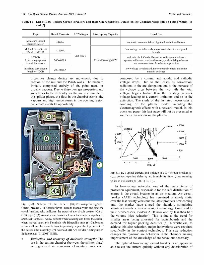
The low voltage circuit breaker has long been used for the protection from damage, of persons and networks, caused by overload or short circuits. Its basic function is to detect a fault condition and, by interrupting continuity, to immediately discontinue electrical flow. Circuit breakers are made in varying sizes, from small devices that protect an individual household appliance up to large switchgear designed to protect high voltage circuits feeding an entire city. Low-voltage types (less than 1000 VAC) are common in domestic, commercial and industrial applications (Table I-1 [1, 2]). General presentations of the low-voltage circuit breaker and of the phenomena occurring in them can be found in the literature for instance in the papers of McBride J.W. and Weaver P.M. [3] and Lindmayer M. and Springstubbe M. [4]. Nevertheless a photograph is presented in Fig. (I-1) showing the different elements of circuit breaker geometry.
From contact opening to the successful breaking process, different instants of arc life can be considered in the geometry:
• Contact opening, jump to the rails (immobility): In normal use current continuity exists between the “opening contact” in the closed position and one rail of the circuit breaker. Due to a network default or to a manual intervention, the opening contact moves leading to arc ignition. During contact opening the arc is elongated and deformed by the magnetic and
*Address correspondence to this author at the Université de Toulouse; UPS,
INPT; LAPLACE (Laboratoire Plasma et Conversion d'Energie); 118 Route
de Narbonne, F-31062 Toulouse Cedex 9, France;
E-mails: [email protected], [email protected]
pressure forces. As the arc cannot be elongated indefinitely, it generally jumps to the rail before total contact opening. After contact opening, the arc remains in the contact region (Fig. II-1).
• Arc movement in the chamber under the effect of the pressure gradient and of the external magnetic field: After the jump of the arc from the opening contacts to the rails, the arc is submitted to different forces, two of which have the greatest effect on arc movement. (1) The first is pressure: due to the temperature increase and thus to the high pressure in the opening contact region compared to the ambient pressure in the splitting chamber, the arc is pushed away from the contacts and into the chamber. (2) The second force is due to the current circulating on the rails. The current-carrying path creates a magnetic field which, combined with the current circulation in the arc, creates a magnetic force which pushes the arc into the splitting chamber. Some designs may use blowout coils or air puffers to aid the process [5].
• Arc in the splitter plates: Under the influence of the two previous forces the arc moves to the splitting chamber. Due to the thickness of the splitters the arc velocity decreases even though the properties of the ferromagnetic splitters act to drive the arc into the cutting chamber. Once it has been divided into several segments, the arc is pushed and elongated generally leading to a successful breaking.
• Restrike phenomena: The arc behaviour in the chamber is complex and restrike can occur between the opening contacts. Restrike can be brought about by the increase of the electric field between the contacts, due to the high value of the arc voltage when the arc enters the splitter plates. The gas
106 The Open Plasma Physics Journal, 2009, Volume 2 Freton and Gonzalez
properties change during arc movement, due to erosion of the rail and the PA66 walls. The medium initially composed entirely of air, gains metal or organic vapours. Due to these new gas properties, and sometimes to the difficulty for the arc to commute to the splitter plates, the flow in the chamber carries the vapours and high temperatures in the opening region can create a restrike opportunity.
Fig. (I-1). Schema of the LCVB (http://en.wikipedia.org/wiki/
Circuit_breaker). (1) Actuator lever - used to manually trip and reset the
circuit breaker. Also indicates the status of the circuit breaker (On or
Off/tripped). (2) Actuator mechanism - forces the contacts together or
apart. (3) Contacts - Allow current when touching and break the current
when moved apart. (4) Terminals (5) Bimetallic strip (6) Calibration
screw - allows the manufacturer to precisely adjust the trip current of
the device after assembly. (7) Solenoid. (8) Arc divider / extinguisher/
Splitter plates (© [2001] IEEE).
• Extinction and recovery of dielectric strength: The arc in the cutting chamber (between the splitter plate) is segmented in numerous elementary arcs each
composed by a column and anodic and cathodic voltage drops. Due to the losses as convection, radiation, to the arc elongation and to the increase of the voltage drop between the two rails the total voltage begins higher than the existing network voltage leading to a current limitation and so to the extinction. The study of the last step necessitates a coupling of the plasma model including the electromagnetic effects with a network model. In this overview paper this last stage will not be presented as we focus this review on the plasma.
Fig. (II-1). Typical current and voltage in a LV circuit breaker [3]
(tcod: contact opening delay, ti: arc immobility time, tr: arc running,
ts: arc in arc stack)(© [2001] IEEE)..
In low-voltage networks, one of the main items of protection equipment, responsible for the safe distribution of energy is the circuit breaker in an air medium. Air circuit breaker (ACB) technology has remained relatively static over the last twenty years but the latest products now coming onto the market have altered the situation, stimulating attention towards advances in ACB technology. Compared to their predecessors, modern ACB now occupy less than half the volume (size reduction). This is due to the trend for smaller areas being allocated for switchboards and the demand for higher packing densities [6]. Nevertheless, to achieve this size reduction, major innovations were required specifically in the contact technology. This size reduction changes the dynamic arc behaviour in the chamber making improvement of the knowledge of arc behaviour necessary.
The optimal low-voltage circuit breaker is an apparatus able to cut the current quickly without any deterioration of
Table I-1. List of Low Voltage Circuit Breakers and their Characteristics. Details on the Characteristics can be Found within [1]
and [2]
Type Rated Currents AC Voltages Interrupting Capacity Usual Use
Miniature Circuit Breaker (MCB)
<100A domestic, commercial and light industrial installations
Molded Case Circuit Breaker MCCB
<1000A low voltage switchboards, motor control center and panel
boards
LVPCB Low voltage power
circuit breakers -
200-4000A multi-tiers in LV switchboards or switchgear cabinets -
systems with selective coordination, synchronizing schemes and automatic transfer scheme application
Insulated case circuit breaker - ICCB
200-4000A
200-800V
25kA-100kA @480V
low voltage switchboard, motor control centers and some transfer switches
Overview of Current Research into Low-Voltage Circuit Breakers The Open Plasma Physics Journal, 2009, Volume 2 107
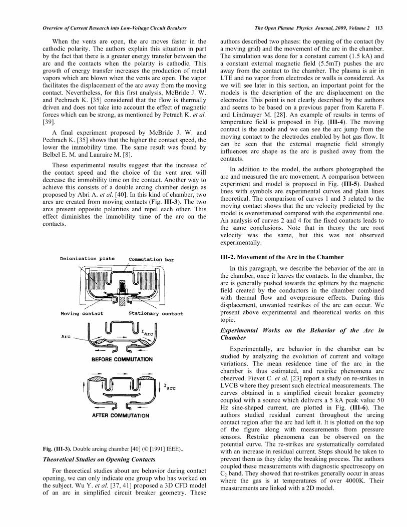
its structure or of the network. The technological focus is on the issues: i) How to decrease the interrupting time and ii) How to diminish apparatus degradation. The two points being correlated. The cutting time represents the life time of the arc from the opening phase to splitting and current interruption (Fig. II-1: from ti to the end of ts). Arc motion in the chamber is determined by the gas properties (dependent on the amount of wall erosion), by the electromagnetic forces (dependent on the current intensity) and by whether external systems exist to optimize their effects (puffer or magnetic system [3]). The studies are thus devoted to the influence of the gas properties on arc behaviour, and to the optimization of the magnetic field effect produced by the current carrying path in the apparatus or by an external system. Of course, even if the arc is quick to arrive in the cutting chamber LVCB technology is based on the current limitation. An increasing the total voltage by multiplying the anode and cathode drops and by producing an elongation of arc length is also necessary. One solution treating the two points simultaneously consists of introducing a symmetrical double break (presented in paragraph III-1, Fig. III-3). The double break contact system [6] provides the opportunity to further elongate the arc to ensure even faster interruption of the short circuit. The typical total interrupting time of a conventional ACB is 70 ms. The use of the double break system ensures interruption in less than 30ms and as the arc energy is shared between the two sets of contacts, surface erosion is reduced. The double break principle will be presented in part III1.2 related to the study of the “Opening of the contact”.
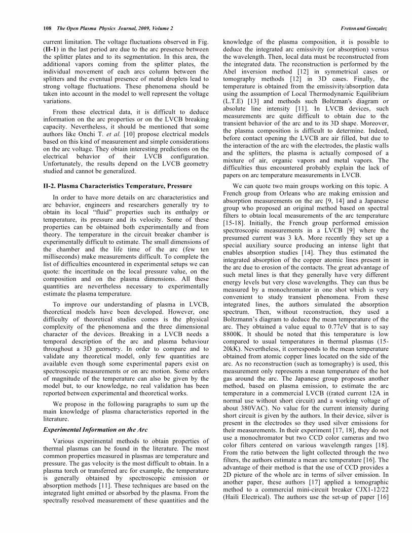
Fig. (II-2). Example of temperature field in a mini LVCB near the
electrodes [18]. Temperatures given from 1kK to 7 kK (Step 1kK)
(© [2004] IEEE)..
As we can see, arc properties and arc behaviour play a very important role in breaking success. Nevertheless, review papers generally deal with the electrical aspects of the arc and do not propose a complete fine description of the arc properties and arc behaviour during the breaking process from its ignition to the current limitation stage. In this paper we propose such overview of the main research conducted by the community. We will try, all along the paper, to confront and discuss experimental and theoretical aspects.
First, we present current research into arc characteristics and properties. Macroscopic electrical characteristics of LVCB are first presented. Then, measurable data such as temperature and pressure are presented and confronted with
results from models. To finish this section we present the way the arc composition on the models. In the second part, we focus on the studies of arc movement in LVCB geometry: from the opening contact to the quenching chamber. We first discuss arc behaviour during contact opening. After, works dealing with arc movement in the chamber are presented and then, part is devoted to the entrance of the arc between the splitter plates.
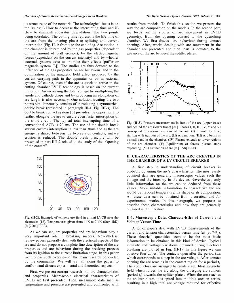
Fig. (II-3). Pressure measurement in front of the arc (upper trace)
and behind the arc (lower trace) [21]. Phases I, II, III, IV, V and VI
correspond to various positions of the arc: (I) Immobility time,
starting with ignition of the arc. (II) Arc motion. (III) Arc burns as
a small band in the chamber. (IV) Plasma extends to lower regions
of the arc chamber. (V) Equilibrium of forces, plasma stops
expanding. (VI) Extinction of arc (© [1998] IEEE)..
II. CHARACTERISTICS OF THE ARC CREATED IN
THE CHAMBER OF A LV CIRCUIT BREAKER
A first step in understanding of circuit breaker is probably obtaining the arc’s characteristics. The most easily obtained data are generally macroscopic values such the voltage and the intensity in the device. Nevertheless, only little information on the arc can be deduced from these values. More suitable information to characterize the arc would be its local temperature, its shape or its composition. All these data can be obtained from theoretical and /or experimental works. In this paragraph, we propose to describe these characteristics and how they are generally obtained in the literature.
II-1. Macroscopic Data, Characteristics of Current and
Voltage Versus Time
A lot of papers deal with LVCB measurements of the current and tension characteristics versus time (as [3, 7-9]). These electrical quantities seem to be the most basic information to be obtained in this kind of device. Typical intensity and voltage variations obtained during electrical breaking are plotted in Fig. (II-1). In this figure we can observe four zones: The contacts open after the period tcod, which corresponds to a step in the arc voltage. After contact opening the arc remains in the contact region for a period ti. The conductors are arranged to create a self blast magnetic field which forces the arc along the diverging arc runners (period tr) towards the splitter plates. When the arc reaches the splitter plates it is spited into multiple arcs in series, resulting in a high total arc voltage required for effective
108 The Open Plasma Physics Journal, 2009, Volume 2 Freton and Gonzalez
current limitation. The voltage fluctuations observed in Fig. (II-1) in the last period are due to the arc presence between the splitter plates and to its segmentation. In this area, the additional vapors coming from the splitter plates, the individual movement of each arcs column between the splitters and the eventual presence of metal droplets lead to strong voltage fluctuations. These phenomena should be taken into account in the model to well represent the voltage variations.
From these electrical data, it is difficult to deduce information on the arc properties or on the LVCB breaking capacity. Nevertheless, it should be mentioned that some authors like Onchi T. et al. [10] propose electrical models based on this kind of measurement and simple considerations on the arc voltage. They obtain interesting predictions on the electrical behavior of their LVCB configuration. Unfortunately, the results depend on the LVCB geometry studied and cannot be generalized.
II-2. Plasma Characteristics Temperature, Pressure
In order to have more details on arc characteristics and arc behavior, engineers and researchers generally try to obtain its local “fluid” properties such its enthalpy or temperature, its pressure and its velocity. Some of these properties can be obtained both experimentally and from theory. The temperature in the circuit breaker chamber is experimentally difficult to estimate. The small dimensions of the chamber and the life time of the arc (few ten milliseconds) make measurements difficult. To complete the list of difficulties encountered in experimental setups we can quote: the incertitude on the local pressure value, on the composition and on the plasma dimensions. All these quantities are nevertheless necessary to experimentally estimate the plasma temperature.
To improve our understanding of plasma in LVCB, theoretical models have been developed. However, one difficulty of theoretical studies comes is the physical complexity of the phenomena and the three dimensional character of the devices. Breaking in a LVCB needs a temporal description of the arc and plasma behaviour throughout a 3D geometry. In order to compare and to validate any theoretical model, only few quantities are available even though some experimental papers exist on spectroscopic measurements or on arc motion. Some orders of magnitude of the temperature can also be given by the model but, to our knowledge, no real validation has been reported between experimental and theoretical works.
We propose in the following paragraphs to sum up the main knowledge of plasma characteristics reported in the literature.
Experimental Information on the Arc
Various experimental methods to obtain properties of thermal plasmas can be found in the literature. The most common properties measured in plasmas are temperature and pressure. The gas velocity is the most difficult to obtain. In a plasma torch or transferred arc for example, the temperature is generally obtained by spectroscopic emission or absorption methods [11]. These techniques are based on the integrated light emitted or absorbed by the plasma. From the spectrally resolved measurement of these quantities and the
knowledge of the plasma composition, it is possible to deduce the integrated arc emissivity (or absorption) versus the wavelength. Then, local data must be reconstructed from the integrated data. The reconstruction is performed by the Abel inversion method [12] in symmetrical cases or tomography methods [12] in 3D cases. Finally, the temperature is obtained from the emissivity/absorption data using the assumption of Local Thermodynamic Equilibrium (L.T.E) [13] and methods such Boltzman's diagram or absolute line intensity [11]. In LVCB devices, such measurements are quite difficult to obtain due to the transient behavior of the arc and to its 3D shape. Moreover, the plasma composition is difficult to determine. Indeed, before contact opening the LVCB are air filled, but due to the interaction of the arc with the electrodes, the plastic walls and the splitters, the plasma is actually composed of a mixture of air, organic vapors and metal vapors. The difficulties thus encountered probably explain the lack of papers on arc temperature measurements in LVCB.
We can quote two main groups working on this topic. A French group from Orleans who are making emission and absorption measurements on the arc [9, 14] and a Japanese group who proposed an original method based on spectral filters to obtain local measurements of the arc temperature [15-18]. Initially, the French group performed emission spectroscopic measurements in a LVCB [9] where the presumed current was 3 kA. More recently they set up a special auxiliary source producing an intense light that enables absorption studies [14]. They thus estimated the integrated absorption of the copper atomic lines present in the arc due to erosion of the contacts. The great advantage of such metal lines is that they generally have very different energy levels but very close wavelengths. They can thus be measured by a monochromator in one shot which is very convenient to study transient phenomena. From these integrated lines, the authors simulated the absorption spectrum. Then, without reconstruction, they used a Boltzmann’s diagram to deduce the mean temperature of the arc. They obtained a value equal to 0.77eV that is to say 8800K. It should be noted that this temperature is low compared to usual temperatures in thermal plasmas (15-20kK). Nevertheless, it corresponds to the mean temperature obtained from atomic copper lines located on the side of the arc. As no reconstruction (such as tomography) is used, this measurement only represents a mean temperature of the hot gas around the arc. The Japanese group proposes another method, based on plasma emission, to estimate the arc temperature in a commercial LVCB ((rated current 12A in normal use without short circuit) and a working voltage of about 380VAC). No value for the current intensity during short circuit is given by the authors. In their device, silver is present in the electrodes so they used silver emissions for their measurements. In their experiment [17, 18], they do not use a monochromator but two CCD color cameras and two color filters centered on various wavelength ranges [18]. From the ratio between the light collected through the two filters, the authors estimate a mean arc temperature [16]. The advantage of their method is that the use of CCD provides a 2D picture of the whole arc in terms of silver emission. In another paper, these authors [17] applied a tomographic method to a commercial mini-circuit breaker CJX1-12/22 (Haili Electrical). The authors use the set-up of paper [16]
Overview of Current Research into Low-Voltage Circuit Breakers The Open Plasma Physics Journal, 2009, Volume 2 109
which is improved to obtain three different images of the arc with each filter. From these images, applying the tomographic method, the authors estimate the local arc temperatures for all planes. An example is given for a plane near the electrodes in Fig. (II-2). We can observe from Fig. (II-2) that the temperature deduced by this method was not very high in the plasma core as it did not exceed 8000K. Generally, in thermal plasmas close to the electrodes one can expect temperatures in the range 10 to 20 kK [19]. This difference can be explained by the method used for the measurements. It is based on the emission of Ag atomic lines which present an emission maximum between 7000 and 9000K. It is therefore expected to measure such low temperatures.
In order to conclude on temperature measurements, from these two approaches found in the literature, we can see that only temperatures in the fringes of the plasma have been experimentally obtained. As noticed by Freton P. et al. [20], care needs to be taken on temperature measurements not to confuse this temperature with that of the arc core. The plasma core temperature, in LVCB is difficult to obtain due to the complexity of achieving spectroscopic measurements on a small transient arc.
Other quantities that have been experimentally obtained in the literature concern the variation of pressure in the chamber during the arc movement [21, 22]. In the work of Lindmayer M. and Paulke J. [21], the study is made in a simplified LVCB geometry, without splitter plates, working in air (under 240V, 50Hz, 8 kA RMS). The measurements were made using two piezo resistive pressure transducers located at the front and the bottom of the chamber. With these two sensors, the authors measured the pressure evolution behind and in front of the arc for three different chamber geometries. An example of relative pressure measurement for one configuration is given in Fig. (II-3). During the arc movement there is an increase of pressure in the chamber which reaches 3 bars (starting from atmospheric pressure). The pressure increase in front of the arc is essentially due to two effects: the heating of surrounding gas by the arc and the ablation of electrodes and wall material. The authors conclude that the increase of pressure in the back of the arc also depends on the cross section dimensions of the chamber. The wider the chamber, the lower the pressure increases. The authors noticed that the rise in pressure at the back of the arc could play a key role on restrikes in the chamber. The same results were found by Doméjean E. et al. [22].
Another way to obtain information on the arc could be to model its behavior. This approach is presented in the next paragraph.
Theoretical Information on the Arc
Before the increase of computer capacities, models were generally 2D and simplified (like in [22] or [23]). These models are generally questionable: how can a 3D object such the arc created in a LVCB be represented in 2D? Nevertheless, since the end of the nineties, a lot of papers propose 3D transient models for LVCB [21, 24-28]. For the arc description, these models generally consider the plasma as an electrical Newtonian fluid which can be described by Navier – Stokes fluid equations and potential scalar and
vector equations. In a Cartesian system (Ox, Oy, Oz), the plasma is described in terms of temperature T, pressure P, velocities components (vx, vy, vz), potential scalar V, potential vector components (Ax, Ay, Az) and other deduced variables such the self-induced magnetic field (Bx, By, Bz) or the current densities (jx, jy, jz). If mixtures of gases are taken into account, a mass fraction equation must also be solved [24]. All these equations are written in the form of the generalized equation (II-1)
t+ v( ) = ( ) + S (II-1)
In this equation, is the variable to be solved, the mass density, the diffusion coefficient and S the source term. For example, for the energy equation, can be: h the static enthalpy of the gas, is /Cp where is the thermal conductivity and Cp the specific heat and S corresponds to additional terms in order to take into account the rare of work due to pressure forces, the rate of work due to viscous stresses, joule effect and radiative losses. More details for other equations can be found in [29].
For all the models of LVCB in the literature, the common hypotheses are the following:
1- The plasma is a laminar Newtonian fluid
2- The plasma is assumed to be in Local Thermodynamic Equilibrium (LTE)
3- The system is generally three dimensional (3D) and described in Cartesian geometry (Ox, Oy, Oz)
With these equations and assumptions it is possible to obtain the arc characteristics in the chamber. A typical temperature field obtained by simulation of a LVCB in air (I=100A) is presented in Fig. (II-4). In Fig. (II-4) we can see that a maximum of 19 kK is obtained in a typical LVCB simulation. This value is more “usual” for thermal plasma medium than the typical ones obtained experimentally in the same kind of devices. Nevertheless as explained before, the theoretical temperatures of the arc core cannot really be compared with experimental temperatures of the fringes and to date, it seems that experimental temperatures of the arc core have not been obtained. Obviously, temperature is not the only data that can be obtained from models. Pressure, velocities and current density distributions can also be calculated. Nevertheless, authors generally focus their reports on temperature fields. However, even though computational fluid dynamics CFD models seem to give interesting information on arc properties, attention should be paid to various difficulties:1) which kind of transport and thermodynamic properties can be used in models? 2) How can the external magnetic field in the chamber and the displacement of the arc be taken into account? 3) How can the initial instant of contact opening be studied? 4) What kinds of validation are available for the models? The first point corresponds to the arc properties and is discussed in the next paragraph. Points 2 and 3 will be discussed at the end of this paper; point 4 is covered all along the paper.
One more point common to experimental and theoretical results is 5) how results obtained generally in simplified geometry can be applied to real breaking devices? Indeed due to the complexity of the LVCB device, extrapolation on
110 The Open Plasma Physics Journal, 2009, Volume 2 Freton and Gonzalez
arc behaviour in real device should be taken with a lot of care. The obtained results in simplified geometry are generally correlated to parametric studies and should be seen as indicators for the understanding of arc behaviour.
Fig. (II-4). Example of modeling temperature fields for LVCB
working in air (I=100A) [26].
II-3. Composition of the Arc
The arc in the chamber moves and along its displacement interacts with the rails (electrodes), the side walls (PA66 walls) and at the final stage of the breaking process with the splitter plates leading from an air medium to a medium composed of air with metal and organic vapours. Two approaches are developed in the models: the first consists of studying arc behaviour assuming a homogeneous gas composed of air or air with organic vapours [30], the second consists of the implementation in the models of an erosion code able to generate vapour depending on the energy transferred to the wall [26]. The types of vapour that can be ablated: iron, silver, carbon, hydrogen, oxygen, nitrogen or copper are so numerous that, to our knowledge, no models separately consider and trace each vapour.
Experimental diagnostics based on imagery can predict the existence of metallic vapours by checking the associated wavelength, nevertheless the quantification remains problematic. Below, we present some studies on this subject found in the literature.
Theoretical Information on the Plasma Composition
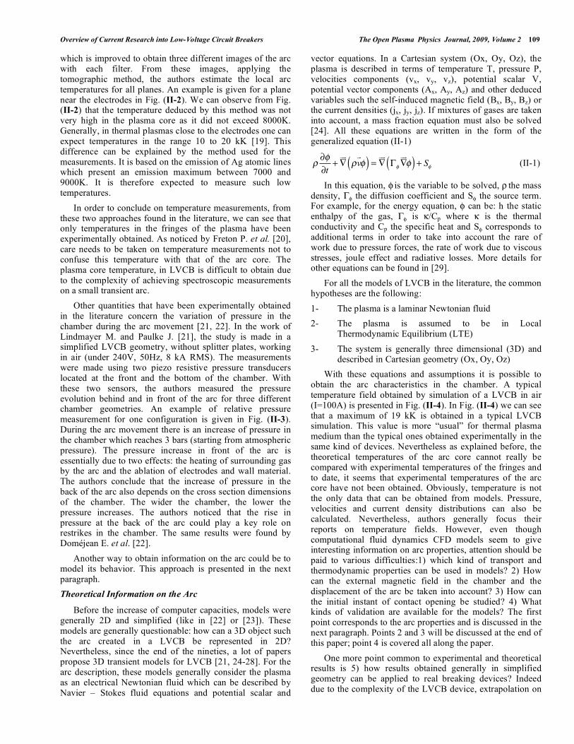
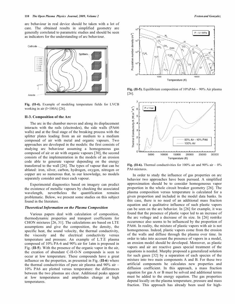
Various papers deal with calculation of composition, thermodynamic properties and transport coefficients for CHON mixtures [26, 31]. The calculations are based on LTE assumptions and give the composition, the density, the specific heat, the sound velocity, the thermal conductivity, the viscosity and the electrical conductivity versus temperature and pressure. An example of L.T.E plasma composed of 10% PA-6 and 90% air for 1atm is proposed in Fig. (II-5). With the presence of the organic vapor in the air, the creation of abundant C-H-O-N compounds is seen to occur at low temperature. These compounds have a great influence on the properties, as presented in Fig. (II-6) where the thermal conductivities of pure air plasma and 90% air – 10% PA6 are plotted versus temperature: the differences between the two plasmas are clear. Additional peaks appear at low temperatures and amplitudes change at high temperatures.
Fig. (II-5). Equilibrium composition of 10%PA6 – 90% Air plasma
[26].
Fig. (II-6). Thermal conductivities for 100% air and 90% air – 0%
PA6 mixtures.
In order to study the influence of gas properties on arc behavior two approaches have been pursued. A simplified approximation should be to consider homogeneous vapor proportion in the whole circuit breaker geometry [26]. The plasma composition versus temperature is calculated for a given proportion and included in the model data banks. In this case, there is no need of an additional mass fraction equation and a qualitative influence of such plastic vapors can be seen on the arc behavior. In [26] for example, it was found that the presence of plastic vapor led to an increase of the arc voltage and a decrease of its size. In [26] restrike occurrence also seems to be influenced by the proportion of PA66. In reality, the mixture of plastic vapors with air is not homogeneous. Indeed, plastic vapors come from the erosion of the walls and diffuse through the plasma over time. In order to take into account the presence of vapors in a model, an erosion model should be developed. Moreover, as plastic vapors and air are reactive gases special treatment of the equations is needed. Murphy proposed a generalized solution for such gases [32] by a separation of each species of the mixture into two main components A and B. For these two artificial components he calculates new properties and diffusion coefficient. In this approach, a mass fraction equation for gas A or B must be solved and additional terms must be added to the energy equation. The gas properties depend locally on the plasma temperature, pressure and mass fraction. This approach has already been used for high-
Overview of Current Research into Low-Voltage Circuit Breakers The Open Plasma Physics Journal, 2009, Volume 2 111
voltage circuit breaker simulation [33] but not yet for LVCB. The difficulty in such an approach is to separate the species into two gases. In real circuit breaker the vapors can be experimentally observed. Nevertheless their quantification in the medium due to the difficulties (Time scale and 3D problem) keeps difficult. Due to the fact that the model currently use simplified geometry and that it exists a difficulty to represent so different vapors distributions (Fe, Ag, Cu, PA66) no direct comparison are possible. Nevertheless even if direct comparison is not possible it is experimentally and theoretically observed that the PA66 vapors presence tends to accelerate the arc velocity displacement in the chamber [26].
Another approach to treat complex mixtures of gases consists in the development of a kinetic model and the resolution of a conservation equation for each species of the plasma. This approach takes into account departures from chemical equilibrium. The thermodynamic and transport properties calculation program needs to be included in the plasma description problem and calculated directly for the geometry for each point during convergence. Due to the time calculation, the transport and thermodynamic properties used assume L.T.E and only departures from the equilibrium of the species densities are estimated. An example of such an approach is proposed by Mercado Cabrera A. et al. in a 1D transient model [30] in air-plastic-metal mixtures. In their model, the authors developed 138 chemical reactions and considered 36 species in the plasma. They show that a weak departure from chemical equilibrium exists. However, such a model heavy on computer time and so can hardly been adapted for complex 3D models.
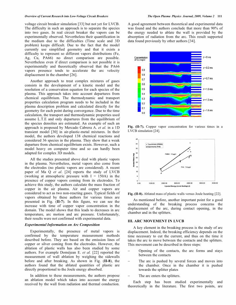
All the studies presented above deal with plastic vapors in the plasma. Nevertheless, metal vapors also come from the electrodes (no plastic vapors are considered). A recent paper of Ma Q et al. [24] reports the study of LVCB (working at atmospheric pressure with I = 150A) in the presence of copper vapors coming from its electrodes. To achieve this study, the authors calculate the mass fraction of copper in the air plasma. Air and copper vapors are considered to act as two non-reacting gases. Typical fields of vapors obtained by these authors for various times are presented in Fig. (II-7). In this figure, we can see the increase with time of copper vapor concentration in the domain. The model shows that this leads to decreases in arc temperature, arc motion and arc pressure. Unfortunately, their results were not confirmed with experimental data.
Experimental Information on Arc Composition
Experimentally, the presence of metal vapors is confirmed by the temperature measurement methods described before. They are based on the emission lines of copper or silver coming from the electrodes. However, the ablation of plastic walls has also been studied by some authors. For example Doméjean E. et al. [22] reported the measurement of wall ablation by weighing the sidewalls before and after breaking. As shown in Fig. (II-8), the authors found that the ablated quantities of plastic are directly proportional to the Joule energy absorbed.
In addition to these measurements, the authors propose an ablation model which takes into account the energy received by the wall from radiation and thermal conduction.
A good agreement between theoretical and experimental data was found and the authors conclude that more than 90% of the energy needed to ablate the wall is provided by the absorption of radiation from the arc. This result supported data found previously by other authors [34].
Fig. (II-7). Copper vapor concentration for various times in a
LVCB simulation [24].
Fig. (II-8). Ablated mass of plastic walls versus Joule heating [22].
As mentioned before, another important point for a good understanding of the breaking process concerns the displacement of the arc, during contact opening, in the chamber and in the splitters.
III. ARC MOVEMENT IN LVCB
A key element in the breaking process is the study of arc displacement. Indeed, the breaking efficiency depends on the time necessary to cut the current, and thus on the time it takes the arc to move between the contacts and the splitters. This movement can be described in three steps:
Opening of the contacts, the arc forms and stays between the contacts
The arc is pushed by several forces and moves into the chamber. Once in the chamber it is pushed towards the splitter plates
The arc enters the splitters.
Each step has been studied experimentally and theoretically in the literature. The first two points, are
112 The Open Plasma Physics Journal, 2009, Volume 2 Freton and Gonzalez
covered just below. The last chapter of this paper is devoted to the third point.
III-1. Opening of the Contacts
The first step in the breaking process is contacts opening and the creation of an arc. This first step is of primary importance, as, in the breaking process, the arc should remain for as little time possible on the contacts. This time is generally called the immobility time. The literature [8, 35, 36] identifies the various parameters that can play a role in the immobility time:
The opening speed of the contacts
The material the contacts are made of
Venting of the geometry
Polarity of the contacts.
Arc current
Various papers study the influence of these points experimentally [8, 35, 36] or theoretically [37, 38]. We present some of these papers above.
Experimental Work on Opening Contacts
Experimentally a quite detailed study of the subject was done by by McBride J. W. and Pechrach K. [35]. In their paper they reported various experiments on different contact materials (see Table III-1), contact velocities (4, 5.5 and 10m/s), peak currents (50A, 1.4kA and 2kA) and venting arrangements of the geometry (open, choked off closed vents at the bottom of the geometry). In several cases they also measured current and voltage and used an imaging system based on optical fibers to obtain pictures of the arc (1000 images/ms).
Table III-1. Contact Materials Used in [35]
Material Composition
CM-3 Silver cadmium tin indium oxides (15% metal oxides)
CM-4 Silver cadmium tin indium oxides (18% metal oxides)
AgNi Silver Nickel (10%)
HGH Silver Nickel (0.15%)
M2-1 Silver tin indium oxides (11% tin indium oxides)
Ag\C Silver graphite contacts
M2 Silver tin indium oxides (15% tin indium oxides)
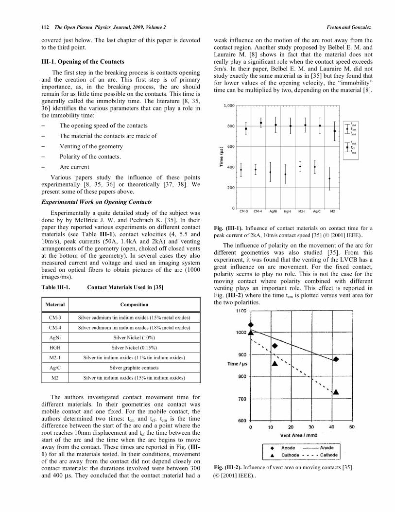
The authors investigated contact movement time for different materials. In their geometries one contact was mobile contact and one fixed. For the mobile contact, the authors determined two times: tcm and tcf. tcm is the time difference between the start of the arc and a point where the root reaches 10mm displacement and tcf the time between the start of the arc and the time when the arc begins to move away from the contact. These times are reported in Fig. (III-
1) for all the materials tested. In their conditions, movement of the arc away from the contact did not depend closely on contact materials: the durations involved were between 300 and 400 μs. They concluded that the contact material had a
weak influence on the motion of the arc root away from the contact region. Another study proposed by Belbel E. M. and Lauraire M. [8] shows in fact that the material does not really play a significant role when the contact speed exceeds 5m/s. In their paper, Belbel E. M. and Lauraire M. did not study exactly the same material as in [35] but they found that for lower values of the opening velocity, the “immobility” time can be multiplied by two, depending on the material [8].
Fig. (III-1). Influence of contact materials on contact time for a
peak current of 2kA, 10m/s contact speed [35] (© [2001] IEEE)..
The influence of polarity on the movement of the arc for different geometries was also studied [35]. From this experiment, it was found that the venting of the LVCB has a great influence on arc movement. For the fixed contact, polarity seems to play no role. This is not the case for the moving contact where polarity combined with different venting plays an important role. This effect is reported in Fig. (III-2) where the time tcm is plotted versus vent area for the two polarities.
Fig. (III-2). Influence of vent area on moving contacts [35].
(© [2001] IEEE)..
Overview of Current Research into Low-Voltage Circuit Breakers The Open Plasma Physics Journal, 2009, Volume 2 113
When the vents are open, the arc moves faster in the cathodic polarity. The authors explain this situation in part by the fact that there is a greater energy transfer between the arc and the contacts when the polarity is cathodic. This growth of energy transfer increases the production of metal vapors which are blown when the vents are open. The vapor facilitates the displacement of the arc away from the moving contact. Nevertheless, for this first analysis, McBride J. W. and Pechrach K. [35] considered that the flow is thermally driven and does not take into account the effect of magnetic forces which can be strong, as mentioned by Petrach K. et al. [39].
A final experiment proposed by McBride J. W. and Pechrach K. [35] shows that the higher the contact speed, the lower the immobility time. The same result was found by Belbel E. M. and Lauraire M. [8].
These experimental results suggest that the increase of the contact speed and the choice of the vent area will decrease the immobility time on the contact. Another way to achieve this consists of a double arcing chamber design as proposed by Abri A. et al. [40]. In this kind of chamber, two arcs are created from moving contacts (Fig. III-3). The two arcs present opposite polarities and repel each other. This effect diminishes the immobility time of the arc on the contacts.
Fig. (III-3). Double arcing chamber [40] (© [1991] IEEE)..
Theoretical Studies on Opening Contacts
For theoretical studies about arc behavior during contact opening, we can only indicate one group who has worked on the subject. Wu Y. et al. [37, 41] proposed a 3D CFD model of an arc in simplified circuit breaker geometry. These
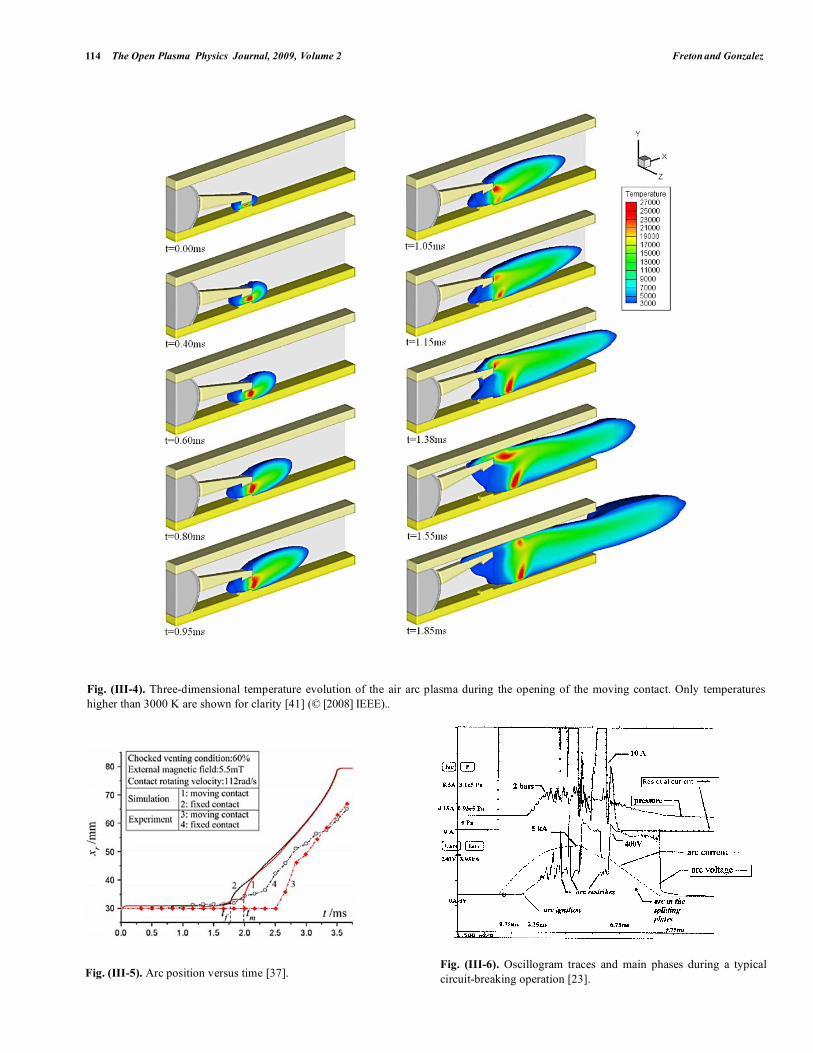
authors described two phases: the opening of the contact (by a moving grid) and the movement of the arc in the chamber. The simulation was done for a constant current (1.5 kA) and a constant external magnetic field (5.5mT) pushes the arc away from the contact to the chamber. The plasma is air in LTE and no vapor from electrodes or walls is considered. As we will see later in this section, an important point for the models is the description of the arc displacement on the electrodes. This point is not clearly described by the authors and seems to be based on a previous paper from Karetta F. and Lindmayer M. [28]. An example of results in terms of temperature field is proposed in Fig. (III-4). The moving contact is the anode and we can see the arc jump from the moving contact to the electrodes enabled by hot gas flow. It can be seen that the external magnetic field strongly influences arc shape as the arc is pushed away from the contacts.
In addition to the model, the authors photographed the arc and measured the arc movement. A comparison between experiment and model is proposed in Fig. (III-5). Dashed lines with symbols are experimental curves and plain lines theoretical. The comparison of curves 1 and 3 related to the moving contact shows that the arc velocity predicted by the model is overestimated compared with the experimental one. An analysis of curves 2 and 4 for the fixed contacts leads to the same conclusions. Note that in theory the arc root velocity was the same, but this was not observed experimentally.
III-2. Movement of the Arc in the Chamber
In this paragraph, we describe the behavior of the arc in the chamber, once it leaves the contacts. In the chamber, the arc is generally pushed towards the splitters by the magnetic field created by the conductors in the chamber combined with thermal flow and overpressure effects. During this displacement, unwanted restrikes of the arc can occur. We present above experimental and theoretical works on this topic.
Experimental Works on the Behavior of the Arc in Chamber
Experimentally, arc behavior in the chamber can be studied by analyzing the evolution of current and voltage variations. The mean residence time of the arc in the chamber is thus estimated, and restrike phenomena are observed. Fievet C. et al. [23] report a study on re-strikes in LVCB where they present such electrical measurements. The curves obtained in a simplified circuit breaker geometry coupled with a source which delivers a 5 kA peak value 50 Hz sine-shaped current, are plotted in Fig. (III-6). The authors studied residual current throughout the arcing contact region after the arc had left it. It is plotted on the top of the figure along with measurements from pressure sensors. Restrike phenomena can be observed on the potential curve. The re-strikes are systematically correlated with an increase in residual current. Steps should be taken to prevent them as they delay the breaking process. The authors coupled these measurements with diagnostic spectroscopy on C2 band. They showed that re-strikes generally occur in areas where the gas is at temperatures of over 4000K. Their measurements are linked with a 2D model.
114 The Open Plasma Physics Journal, 2009, Volume 2 Freton and Gonzalez
Fig. (III-5). Arc position versus time [37].
Fig. (III-6). Oscillogram traces and main phases during a typical
circuit-breaking operation [23].
Fig. (III-4). Three-dimensional temperature evolution of the air arc plasma during the opening of the moving contact. Only temperatures
higher than 3000 K are shown for clarity [41] (© [2008] IEEE)..
Overview of Current Research into Low-Voltage Circuit Breakers The Open Plasma Physics Journal, 2009, Volume 2 115
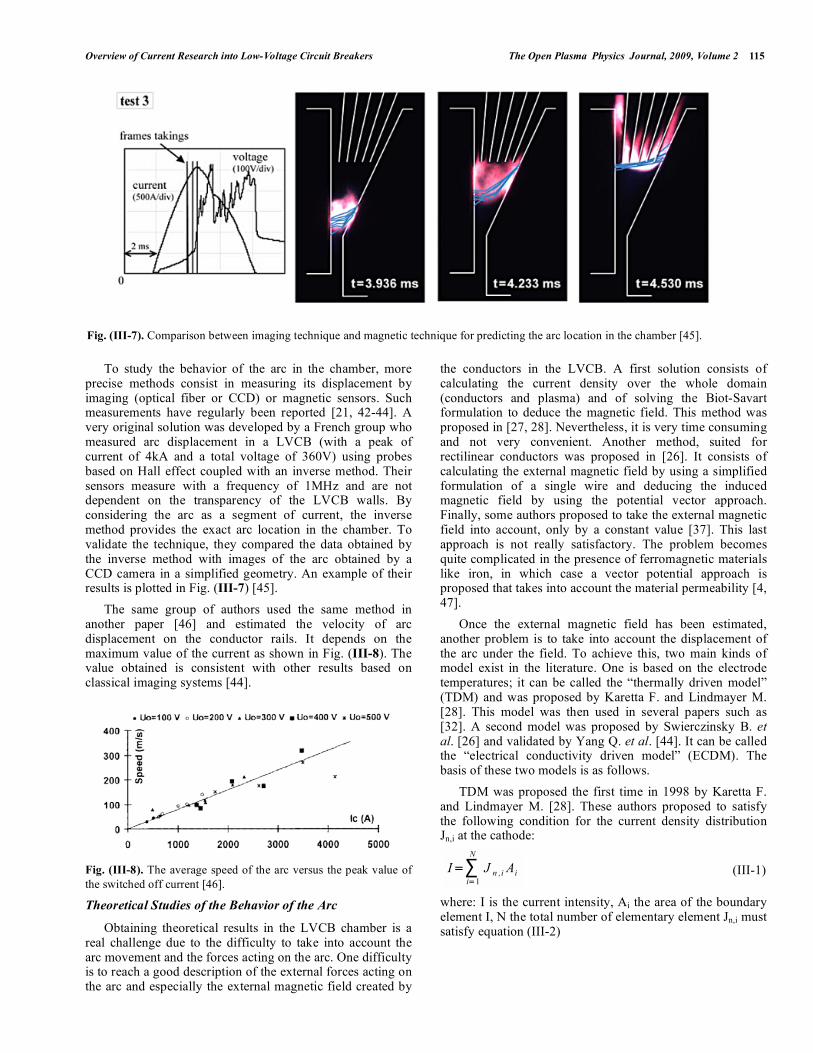
To study the behavior of the arc in the chamber, more precise methods consist in measuring its displacement by imaging (optical fiber or CCD) or magnetic sensors. Such measurements have regularly been reported [21, 42-44]. A very original solution was developed by a French group who measured arc displacement in a LVCB (with a peak of current of 4kA and a total voltage of 360V) using probes based on Hall effect coupled with an inverse method. Their sensors measure with a frequency of 1MHz and are not dependent on the transparency of the LVCB walls. By considering the arc as a segment of current, the inverse method provides the exact arc location in the chamber. To validate the technique, they compared the data obtained by the inverse method with images of the arc obtained by a CCD camera in a simplified geometry. An example of their results is plotted in Fig. (III-7) [45].
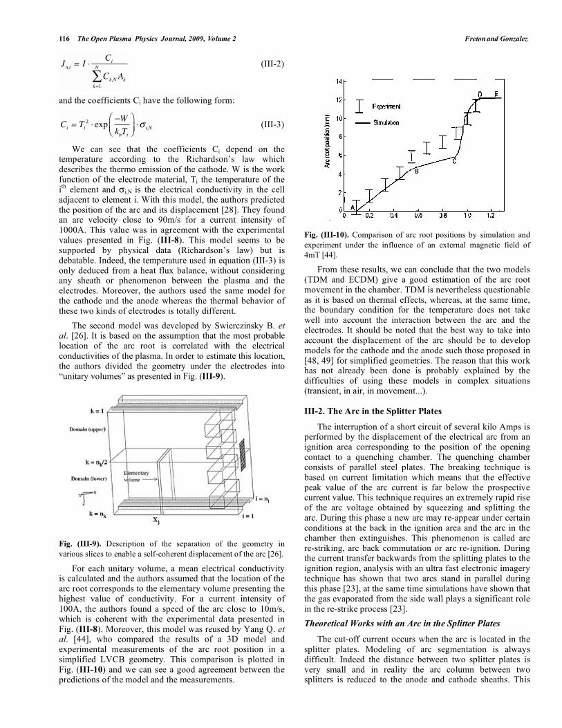
The same group of authors used the same method in another paper [46] and estimated the velocity of arc displacement on the conductor rails. It depends on the maximum value of the current as shown in Fig. (III-8). The value obtained is consistent with other results based on classical imaging systems [44].
Fig. (III-8). The average speed of the arc versus the peak value of
the switched off current [46].
Theoretical Studies of the Behavior of the Arc
Obtaining theoretical results in the LVCB chamber is a real challenge due to the difficulty to take into account the arc movement and the forces acting on the arc. One difficulty is to reach a good description of the external forces acting on the arc and especially the external magnetic field created by
the conductors in the LVCB. A first solution consists of calculating the current density over the whole domain (conductors and plasma) and of solving the Biot-Savart formulation to deduce the magnetic field. This method was proposed in [27, 28]. Nevertheless, it is very time consuming and not very convenient. Another method, suited for rectilinear conductors was proposed in [26]. It consists of calculating the external magnetic field by using a simplified formulation of a single wire and deducing the induced magnetic field by using the potential vector approach. Finally, some authors proposed to take the external magnetic field into account, only by a constant value [37]. This last approach is not really satisfactory. The problem becomes quite complicated in the presence of ferromagnetic materials like iron, in which case a vector potential approach is proposed that takes into account the material permeability [4, 47].
Once the external magnetic field has been estimated, another problem is to take into account the displacement of the arc under the field. To achieve this, two main kinds of model exist in the literature. One is based on the electrode temperatures; it can be called the “thermally driven model” (TDM) and was proposed by Karetta F. and Lindmayer M. [28]. This model was then used in several papers such as [32]. A second model was proposed by Swierczinsky B. et al. [26] and validated by Yang Q. et al. [44]. It can be called the “electrical conductivity driven model” (ECDM). The basis of these two models is as follows.
TDM was proposed the first time in 1998 by Karetta F. and Lindmayer M. [28]. These authors proposed to satisfy the following condition for the current density distribution Jn,i at the cathode:
I=i=1
N
J n ,i Ai (III-1)
where: I is the current intensity, Ai the area of the boundary element I, N the total number of elementary element Jn,i must satisfy equation (III-2)
Fig. (III-7). Comparison between imaging technique and magnetic technique for predicting the arc location in the chamber [45].
116 The Open Plasma Physics Journal, 2009, Volume 2 Freton and Gonzalez
Jn,i = ICi
Ck,N Akk=1
N (III-2)
and the coefficients Ci have the following form:
Ci = Ti2 exp
W
kbTii,N (III-3)
We can see that the coefficients Ci depend on the temperature according to the Richardson’s law which describes the thermo emission of the cathode. W is the work function of the electrode material, Ti the temperature of the ith
element and i,N is the electrical conductivity in the cell adjacent to element i. With this model, the authors predicted the position of the arc and its displacement [28]. They found an arc velocity close to 90m/s for a current intensity of 1000A. This value was in agreement with the experimental values presented in Fig. (III-8). This model seems to be supported by physical data (Richardson’s law) but is debatable. Indeed, the temperature used in equation (III-3) is only deduced from a heat flux balance, without considering any sheath or phenomenon between the plasma and the electrodes. Moreover, the authors used the same model for the cathode and the anode whereas the thermal behavior of these two kinds of electrodes is totally different.
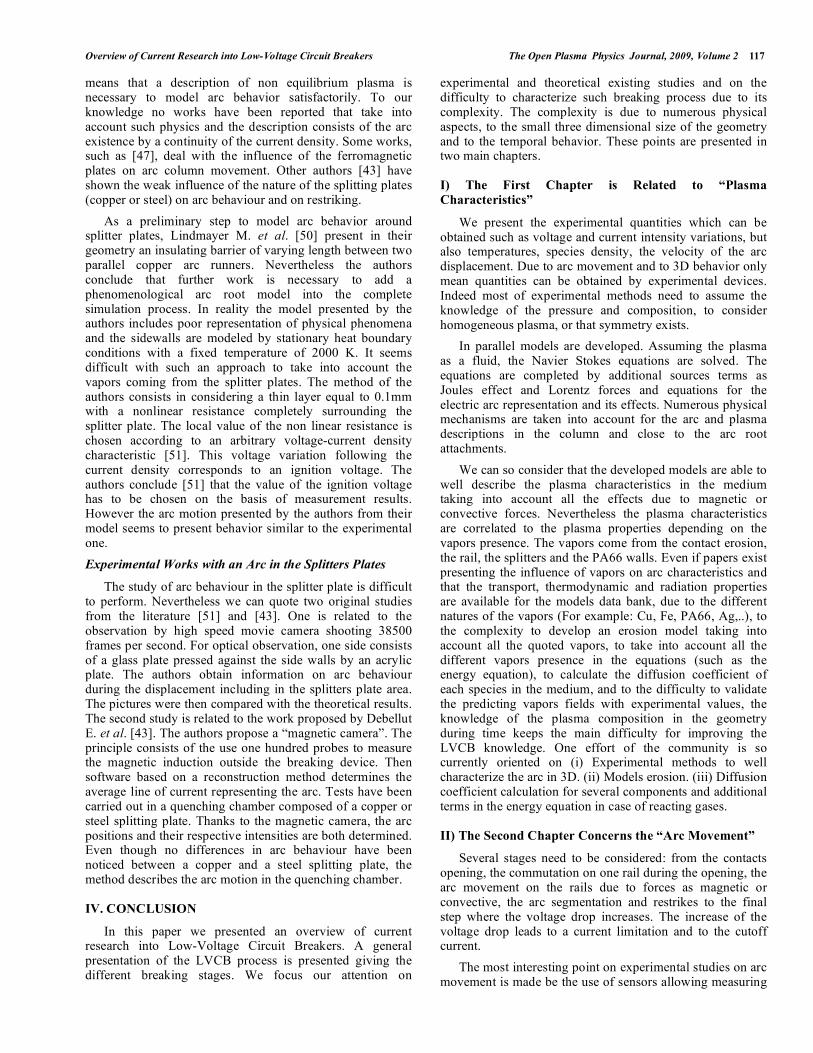
The second model was developed by Swierczinsky B. et al. [26]. It is based on the assumption that the most probable location of the arc root is correlated with the electrical conductivities of the plasma. In order to estimate this location, the authors divided the geometry under the electrodes into “unitary volumes” as presented in Fig. (III-9).
Fig. (III-9). Description of the separation of the geometry in
various slices to enable a self-coherent displacement of the arc [26].
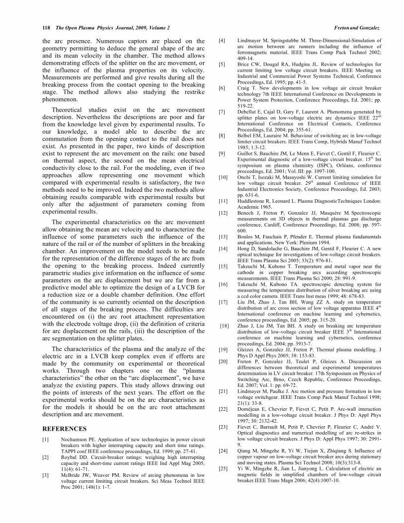
For each unitary volume, a mean electrical conductivity is calculated and the authors assumed that the location of the arc root corresponds to the elementary volume presenting the highest value of conductivity. For a current intensity of 100A, the authors found a speed of the arc close to 10m/s, which is coherent with the experimental data presented in Fig. (III-8). Moreover, this model was reused by Yang Q. et al. [44], who compared the results of a 3D model and experimental measurements of the arc root position in a simplified LVCB geometry. This comparison is plotted in Fig. (III-10) and we can see a good agreement between the predictions of the model and the measurements.
Fig. (III-10). Comparison of arc root positions by simulation and
experiment under the influence of an external magnetic field of
4mT [44].
From these results, we can conclude that the two models (TDM and ECDM) give a good estimation of the arc root movement in the chamber. TDM is nevertheless questionable as it is based on thermal effects, whereas, at the same time, the boundary condition for the temperature does not take well into account the interaction between the arc and the electrodes. It should be noted that the best way to take into account the displacement of the arc should be to develop models for the cathode and the anode such those proposed in [48, 49] for simplified geometries. The reason that this work has not already been done is probably explained by the difficulties of using these models in complex situations (transient, in air, in movement...).
III-2. The Arc in the Splitter Plates
The interruption of a short circuit of several kilo Amps is performed by the displacement of the electrical arc from an ignition area corresponding to the position of the opening contact to a quenching chamber. The quenching chamber consists of parallel steel plates. The breaking technique is based on current limitation which means that the effective peak value of the arc current is far below the prospective current value. This technique requires an extremely rapid rise of the arc voltage obtained by squeezing and splitting the arc. During this phase a new arc may re-appear under certain conditions at the back in the ignition area and the arc in the chamber then extinguishes. This phenomenon is called arc re-striking, arc back commutation or arc re-ignition. During the current transfer backwards from the splitting plates to the ignition region, analysis with an ultra fast electronic imagery technique has shown that two arcs stand in parallel during this phase [23], at the same time simulations have shown that the gas evaporated from the side wall plays a significant role in the re-strike process [23].
Theoretical Works with an Arc in the Splitter Plates
The cut-off current occurs when the arc is located in the splitter plates. Modeling of arc segmentation is always difficult. Indeed the distance between two splitter plates is very small and in reality the arc column between two splitters is reduced to the anode and cathode sheaths. This
Overview of Current Research into Low-Voltage Circuit Breakers The Open Plasma Physics Journal, 2009, Volume 2 117
means that a description of non equilibrium plasma is necessary to model arc behavior satisfactorily. To our knowledge no works have been reported that take into account such physics and the description consists of the arc existence by a continuity of the current density. Some works, such as [47], deal with the influence of the ferromagnetic plates on arc column movement. Other authors [43] have shown the weak influence of the nature of the splitting plates (copper or steel) on arc behaviour and on restriking.
As a preliminary step to model arc behavior around splitter plates, Lindmayer M. et al. [50] present in their geometry an insulating barrier of varying length between two parallel copper arc runners. Nevertheless the authors conclude that further work is necessary to add a phenomenological arc root model into the complete simulation process. In reality the model presented by the authors includes poor representation of physical phenomena and the sidewalls are modeled by stationary heat boundary conditions with a fixed temperature of 2000 K. It seems difficult with such an approach to take into account the vapors coming from the splitter plates. The method of the authors consists in considering a thin layer equal to 0.1mm with a nonlinear resistance completely surrounding the splitter plate. The local value of the non linear resistance is chosen according to an arbitrary voltage-current density characteristic [51]. This voltage variation following the current density corresponds to an ignition voltage. The authors conclude [51] that the value of the ignition voltage has to be chosen on the basis of measurement results. However the arc motion presented by the authors from their model seems to present behavior similar to the experimental one.
Experimental Works with an Arc in the Splitters Plates
The study of arc behaviour in the splitter plate is difficult to perform. Nevertheless we can quote two original studies from the literature [51] and [43]. One is related to the observation by high speed movie camera shooting 38500 frames per second. For optical observation, one side consists of a glass plate pressed against the side walls by an acrylic plate. The authors obtain information on arc behaviour during the displacement including in the splitters plate area. The pictures were then compared with the theoretical results. The second study is related to the work proposed by Debellut E. et al. [43]. The authors propose a “magnetic camera”. The principle consists of the use one hundred probes to measure the magnetic induction outside the breaking device. Then software based on a reconstruction method determines the average line of current representing the arc. Tests have been carried out in a quenching chamber composed of a copper or steel splitting plate. Thanks to the magnetic camera, the arc positions and their respective intensities are both determined. Even though no differences in arc behaviour have been noticed between a copper and a steel splitting plate, the method describes the arc motion in the quenching chamber.
IV. CONCLUSION
In this paper we presented an overview of current research into Low-Voltage Circuit Breakers. A general presentation of the LVCB process is presented giving the different breaking stages. We focus our attention on
experimental and theoretical existing studies and on the difficulty to characterize such breaking process due to its complexity. The complexity is due to numerous physical aspects, to the small three dimensional size of the geometry and to the temporal behavior. These points are presented in two main chapters.
I) The First Chapter is Related to “Plasma
Characteristics”
We present the experimental quantities which can be obtained such as voltage and current intensity variations, but also temperatures, species density, the velocity of the arc displacement. Due to arc movement and to 3D behavior only mean quantities can be obtained by experimental devices. Indeed most of experimental methods need to assume the knowledge of the pressure and composition, to consider homogeneous plasma, or that symmetry exists.
In parallel models are developed. Assuming the plasma as a fluid, the Navier Stokes equations are solved. The equations are completed by additional sources terms as Joules effect and Lorentz forces and equations for the electric arc representation and its effects. Numerous physical mechanisms are taken into account for the arc and plasma descriptions in the column and close to the arc root attachments.
We can so consider that the developed models are able to well describe the plasma characteristics in the medium taking into account all the effects due to magnetic or convective forces. Nevertheless the plasma characteristics are correlated to the plasma properties depending on the vapors presence. The vapors come from the contact erosion, the rail, the splitters and the PA66 walls. Even if papers exist presenting the influence of vapors on arc characteristics and that the transport, thermodynamic and radiation properties are available for the models data bank, due to the different natures of the vapors (For example: Cu, Fe, PA66, Ag,..), to the complexity to develop an erosion model taking into account all the quoted vapors, to take into account all the different vapors presence in the equations (such as the energy equation), to calculate the diffusion coefficient of each species in the medium, and to the difficulty to validate the predicting vapors fields with experimental values, the knowledge of the plasma composition in the geometry during time keeps the main difficulty for improving the LVCB knowledge. One effort of the community is so currently oriented on (i) Experimental methods to well characterize the arc in 3D. (ii) Models erosion. (iii) Diffusion coefficient calculation for several components and additional terms in the energy equation in case of reacting gases.
II) The Second Chapter Concerns the “Arc Movement”
Several stages need to be considered: from the contacts opening, the commutation on one rail during the opening, the arc movement on the rails due to forces as magnetic or convective, the arc segmentation and restrikes to the final step where the voltage drop increases. The increase of the voltage drop leads to a current limitation and to the cutoff current.
The most interesting point on experimental studies on arc movement is made be the use of sensors allowing measuring
118 The Open Plasma Physics Journal, 2009, Volume 2 Freton and Gonzalez
the arc presence. Numerous captors are placed on the geometry permitting to deduce the general shape of the arc and its mean velocity in the chamber. The method allows demonstrating effects of the splitter on the arc movement, or the influence of the plasma properties on its velocity. Measurements are performed and give results during all the breaking process from the contact opening to the breaking stage. The method allows also studying the restrike phenomenon.
Theoretical studies exist on the arc movement description. Nevertheless the descriptions are poor and far from the knowledge level given by experimental results. To our knowledge, a model able to describe the arc commutation from the opening contact to the rail does not exist. As presented in the paper, two kinds of description exist to represent the arc movement on the rails: one based on thermal aspect, the second on the mean electrical conductivity close to the rail. For the modeling, even if two approaches allow representing one movement which compared with experimental results is satisfactory, the two methods need to be improved. Indeed the two methods allow obtaining results comparable with experimental results but only after the adjustment of parameters coming from experimental results.
The experimental characteristics on the arc movement allow obtaining the mean arc velocity and to characterize the influence of some parameters such the influence of the nature of the rail or of the number of splitters in the breaking chamber. An improvement on the model needs to be made for the representation of the difference stages of the arc from the opening to the breaking process. Indeed currently parametric studies give information on the influence of some parameters on the arc displacement but we are far from a predictive model able to optimize the design of a LVCB for a reduction size or a double chamber definition. One effort of the community is so currently oriented on the description of all stages of the breaking process. The difficulties are encountered on (i) the arc root attachment representation with the electrode voltage drop, (ii) the definition of criteria for arc displacement on the rails, (iii) the description of the arc segmentation on the splitter plates.
The characteristics of the plasma and the analyze of the electric arc in a LVCB keep complex even if efforts are made by the community on experimental or theoretical works. Through two chapters one on the “plasma characteristics” the other on the “arc displacement”, we have analyze the existing papers. This study allows drawing out the points of interests of the next years. The effort on the experimental works should be on the arc characteristics as for the models it should be on the arc root attachment description and arc movement.
REFERENCES
[1] Nochumson PE. Application of new technologies in power circuit breakers with higher interrupting capacity and short time ratings.
TAPPI conf IEEE conference proceedings, Ed. 1999; pp. 27-41. [2] Roybal DD. Circuit-breaker ratings: weighing high interrupting
capacity and short-time current ratings IEEE Ind Appl Mag 2005; 11(4): 61-71.
[3] McBride JW, Weaver PM. Review of arcing phenomena in low voltage current limiting circuit breakers. Sci Meas Technol IEEE
Proc 2001; 148(1): 1-7.
[4] Lindmayer M, Springstubbe M. Three-Dimensional-Simulation of
arc motion between arc runners including the influence of ferromagnetic material. IEEE Trans Comp Pack Technol 2002;
409-14. [5] Brice CW, Dougal RA, Hudgins JL. Review of technologies for
current limiting low voltage circuit breakers. IEEE Meeting on Industrial and Commercial Power Systems Technical, Conference
Proceedings, Ed. 1995; pp. 41-5. [6] Craig T. New developments in low voltage air circuit breaker
technology 7th IEEE International Conference on Developments in Power System Protection, Conference Proceedings, Ed. 2001; pp.
519-22. [7] Debellut E, Cajal D, Gary F, Laurent A. Phenomena generated by
splitter plates on low-voltage electric arc dynamics IEEE 22nd International Conference on Electrical Contacts, Conference
Proceedings, Ed. 2004; pp. 355-61. [8] Belbel EM, Lauraire M. Behaviour of switching arc in low-voltage
limiter circuit breakers. IEEE Trans Comp, Hybrids Manuf Technol 1985; 1:3-12.
[9] Guillot S, Bauchire JM, Le Menn E, Fievet C, Gentil F, Fleurier C. Experimental diagnostic of a low-voltage circuit breaker. 15th Int
symposium on plasma chemistry (ISPC), Orléans, conference proceedings, Ed. 2001; Vol. III: pp. 1097-100.
[10] Onchi T, Isozaki M, Masayoshi W. Current limiting simulation for low voltage circuit breaker. 29th annual Conference of IEEE
Industrial Electronics Society, Conference Proceedings, Ed. 2003; pp. 631-6.
[11] Huddlestone R, Leonard L. Plasma DiagnosticTechniques London: Academic 1965.
[12] Benech J, Freton P, Gonzalez JJ, Masquère M. Spectroscopic measurements on 3D objects in thermal plasmas gas discharge
conference, Cardiff, Conference Proceedings, Ed. 2008; pp. 597-600.
[13] Boulos M, Fauchais P, Pfender E. Thermal plasma fundamentals and applications. New York: Plenium 1994.
[14] Hong D, Sandolache G, Bauchire JM, Gentil F, Fleurier C. A new optical technique for investigations of low-voltage circuit breakers.
IEEE Trans Plasma Sci 2005; 33(2): 976-81. [15] Takeuchi M, Kubono T. Temperature and metal vapor near the
cathode in copper breaking arcs according spectroscopic measurements. IEEE Trans Plasma Sci 2000; 28: 991-9.
[16] Takeuchi M, Kubono TA. spectroscopic detecting system for measuring the temperature distribution of silver breaking arc using
a ccd color camera. IEEE Trans Inst meas 1999; 48: 678-83. [17] Liu JM, Zhao J, Tan BH, Wang ZZ A. study on temperature
distribution of arc cross section of low voltage apparatus IEEE 4th International conference on machine learning and cybernetics,
conference proceedings, Ed. 2005; pp. 315-20. [18] Zhao J, Liu JM, Tan BH. A study on breaking arc temperature
distribution of low-voltage circuit breaker IEEE 3th International conference on machine learning and cybernetics, conference
proceedings, Ed. 2004; pp. 3913-7. [19] Gleizes A, Gonzalez JJ, Freton P. Thermal plasma modelling. J
Phys D Appl Phys 2005; 38: 153-83. [20] Freton P, Gonzalez JJ, Teulet P, Gleizes A. Discussion on
differences between theoretical and experimental temperatures determination in LV circuit breaker. 17th Symposium on Physics of
Switching Arc, Brno, Czech Republic, Conference Proceedings, Ed. 2007; Vol. 1: pp. 69-72.
[21] Lindmayer M, Paulke J. Arc motion and pressure formation in low voltage switchgear. IEEE Trans Comp Pack Manuf Technol 1998;
21(1): 33-8. [22] Doméjean E, Chevrier P, Fievet C, Petit P. Arc-wall interaction
modelling in a low-voltage circuit breaker. J Phys D: Appl Phys 1997; 30: 2132-42.
[23] Fievet C, Barrault M, Petit P, Chevrier P, Fleurier C, André V. Optical diagnostics and numerical modelling of arc re-strikes in
low voltage circuit breakers. J Phys D: Appl Phys 1997; 30: 2991-9.
[24] Qiang M, Mingzhe R, Yi W, Tiejun X, Zhiqiang S. Influence of copper vapour on low-voltage circuit breaker arcs during stationary
and moving states. Plasma Sci Technol 2008; 10(3):313-8. [25] Yi W, Mingzhe R, Jian L, Jianyong L. Calculation of electric an
magnetic fields in simplified chambers of low-voltage circuit breaker.IEEE Trans Magn 2006; 42(4):1007-10.
Overview of Current Research into Low-Voltage Circuit Breakers The Open Plasma Physics Journal, 2009, Volume 2 119
[26] Swierczynski B, Gonzalez JJ, Teulet P, Freton P, Gleizes A.
Advances in low-voltage circuit breaker modelling. J Phys D: Appl Phys 2004; 37:595-609.
[27] Baudoin F, Gonzalez JJ, Checchin P. Study of the curvature of the electrical arc in low voltage breaking devices: influence of the
external magnetic field. J Phys D: Appl Phys 2005; 38: 3778-91. [28] Karetta F, Lindmayer M. Simulation of the gas dynamic and
electromagnetic processes in low voltage switching arcs. IEEE Trans comp pack Technol 1998; 21: 96-103.
[29] Gonzalez JJ, Freton P, Gleizes A. Comparison between two and three dimensional models: gas injection and arc attachment. J Phys
D: Appl Phys 2002; 35: 3181-91. [30] Mercado Cabrera A, Teulet P, Razafinimanana M, Gonzalez JJ,
Gleizes A. Calculation of the decaying arc composition in a low-voltage circuit breaker. 14th Symposium on Physics of Switching
Arc FSO, Brno, Czech Republic, conference proceedings, Ed. 2001; pp. 27-30.
[31] André P. The influence of graphite on the composition and thermodynamic properties of plasma formed in ablated vapour of
PMMA, PA6-6, PETP, POM and PE used in circuit-breakers. J Phys D: Appl Phys 1997; 30: 475-93.
[32] Murphy AB. Thermal plasmas in gas mixtures. J Phys D: Appl Phys 2001; 34(20): R151-R173.
[33] Zhang JL, Yan JD, Murphy AB, Hall W, Fang MTC. Computational investigation of arc behaviour in an auto-expansion
circuit breaker contaminated by ablated nozzle vapour. IEEE Trans plasma Sci 2002; 30(2): 707-19.
[34] Kovitya P. Ablation-stabilized arcs in nylon and boric acid tubes IEEE Trans Plasma Sci 1987; 15: 294-301.
[35] McBride JW, Pechrach K. Arc root commutation from moving contacts in low voltage devices. IEEE Trans Comp Pack Technol
2001; 24(3): 331-6. [36] Lindmayer M. The influence of contact materials and chamber wall
materials on the migration and the splitting of the arc extinction chambers. IEEE Trans Parts Hybrids Pack 1973; 9(1): 45-9.
[37] Yi W, Mingzhe R, Qian Y, Guangxia H. Numerical analysis of arc plasma behaviour during contact opening process in low-voltage
switching device. J Phys D: Appl Phys 2007; 40: 795-802. [38] Ma Q, Rong M, Wu Y, Xu T, Sun Z. Simulation and experimental
study of arc column expansion after ignition in low-voltage circuit breakers. Plasma Sci Technol 2008; 10(4):438-45.
[39] Pechrach K, McBride JW, Weaver PM. The correlation of
magnetic, gas dynamic and thermal effects on arc mobility in low contact velocity circuit breakers. IEEE 48th International
conference on Electrical Contacts, conference proceedings, Ed. 2002; pp. 86-94.
[40] Abri A, Kjellnas S, Nordgren R, Lindgren S, Banghammar LA. Mechanism of interaction between electric arc and breaking
chamber in low voltage current limiting circuit breakers. IEEE Trans Ind Appl 1991 ; 27(5) : 841-8.
[41] Yi W, Mingzhe R, Fei Y, Murphy AB, Qiang M, Zhiqiang S, Xiaohua W. Numerical modeling of arc root transfer during contact
opening in a low-voltage air circuit breaker. IEEE Trans Plasma Sci 2008; 36: 1074-5.
[42] Cajal D, Laurent A, Gary F, Mercier M, Servant S. A study of the various phases of the break in a low-voltage circuit breaker thanks
to a magnetic camera. J Phys D: Appl Phys 1999; 32: 1130-5. [43] Debellut E, Gary F, Cajal D, Laurent A. Study of re-strike
phenomena in a low-voltage breaking device by means of the magnetic camera. J Phys D:Appl Phys 2001; 34: 1665-74.
[44] Qian Y, Mingzhe R, Murphy AB. The influence of medium on low-voltage circuit breaker arcs. Plasma Sci Technol 2006; 8(6):
680-4. [45] Brdys C, Toumazet JP, Laurent A, Ponthenier JL. Optical and
magnetic diagnostics of the electric arc dynamics in a low voltage circuit breaker. Meas Sci Technol 2002; 13: 1146-53.
[46] Mercier M, Cajal D, Laurent A, Velleaud G, Gary F. Evolution of a low voltage electric arc. J Phys D: Appl Phys 1996; 29: 95-8.
[47] Wu Y, Mingzhe R, Qian Y, Guangxia H. Numerical analysis of the arc plasma in simplified low-voltage circuit breaker chamber with
ferromagnetic materials. Plasma Sci Technol 2005; 7(4):2977-81. [48] Benilov MS, Marotta A. A model of the cathode region of
atmospheric pressure arcs. J Phys D: Appl Phys 1995; 28: 1869-82. [49] Cayla F, Freton P, Gonzalez JJ. Arc cathode interaction model.
IEEE Trans Plasma Sci 2008; 46(4-5): 1944-54. [50] Lindmayer M, Marzahn E, Mutzke A, Ruther T, Springstubbe M.
The process of arc-Splitting between metal plates in low voltage arc chutes. IEEE Trans Comp Pack Technol 2006; 29(2): 26-34.
[51] Mutzke A, Ruther T, Kurrat M, Lindmayer M, Wilkening ED. Modelling the arc splitting process in low-Voltage arc chutes. IEEE
53rd international conference on Electrical contacts, conference proceedings, Ed. 2007; pp. 175-82.
Received: May 15, 2009 Revised: June 29, 2009 Accepted: June 30, 2009
© Freton and Gonzalez; Licensee Bentham Open.
This is an open access article licensed under the terms of the Creative Commons Attribution Non-Commercial License (http://creativecommons.org/licenses/by-
nc/3.0/) which permits unrestricted, non-commercial use, distribution and reproduction in any medium, provided the work is properly cited.