Embed Size (px)
Citation preview
Overview of Quantum
Gates for Ion Trapped
Quantum ComputersAndrew Schaffer
OPTI 646
1
Most successful approaches so far
The Molmer-Sorensen (MS) gate
Proposed in 1999 by Anders Sorensen and Klaus Molmer
Physically realized for clock-state qubits with GHz laser frequency modulation
Can achieve high fidelities with extremely well-controlled hardware and error
correction
The Light-Shift (LS) gate
Not yet developed using clock-state qubit (not yet a universal gate)
Entanglement gate demonstrated this year on clock-state qubits by Honeywell
2
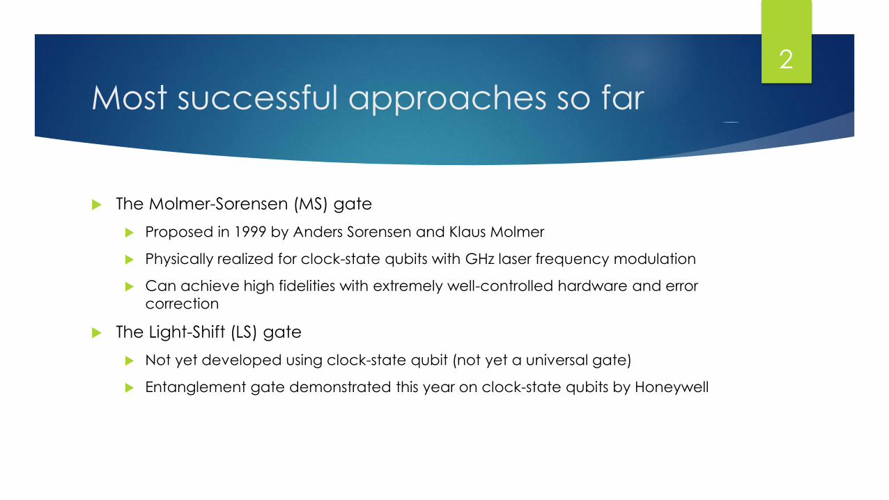
Ion Traps
20 ions cooled and trapped in a
linear ion trap
Traps are nearly harmonic
Use quantum harmonic oscillator
to approximate ground state
motional energy and subsequent
energy levels
3
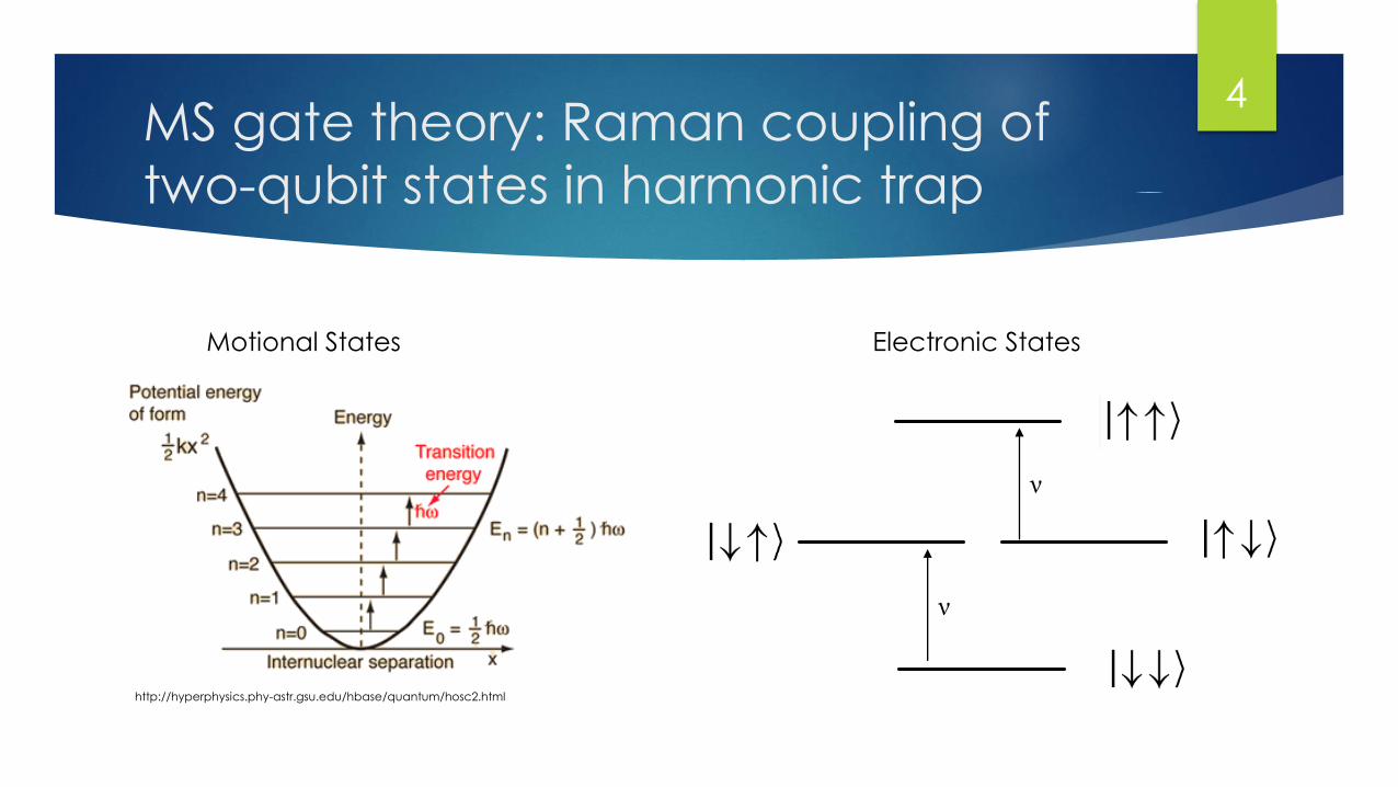
MS gate theory: Raman coupling of
two-qubit states in harmonic trap
http://hyperphysics.phy-astr.gsu.edu/hbase/quantum/hosc2.html
Motional States Electronic States
ν
ν
4
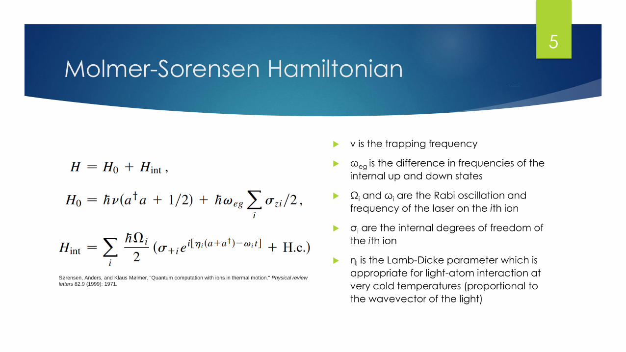
Molmer-Sorensen Hamiltonian
Sørensen, Anders, and Klaus Mølmer. "Quantum computation with ions in thermal motion." Physical review
letters 82.9 (1999): 1971.
ν is the trapping frequency
ωeg is the difference in frequencies of the
internal up and down states
Ωi and ωi are the Rabi oscillation and
frequency of the laser on the ith ion
σi are the internal degrees of freedom of
the ith ion
ηi is the Lamb-Dicke parameter which is
appropriate for light-atom interaction at
very cold temperatures (proportional to
the wavevector of the light)
5
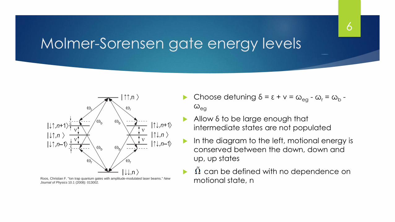
Molmer-Sorensen gate energy levels
Choose detuning δ = ε + ν = ωeg - ωr = ωb -
ωeg
Allow δ to be large enough that
intermediate states are not populated
In the diagram to the left, motional energy is
conserved between the down, down and
up, up states
can be defined with no dependence on
motional state, nRoos, Christian F. "Ion trap quantum gates with amplitude-modulated laser beams." New
Journal of Physics 10.1 (2008): 013002.
6
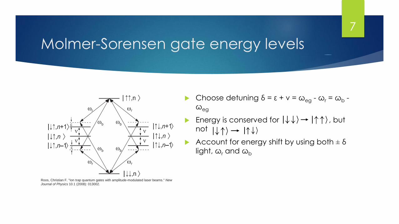
Molmer-Sorensen gate energy levels
Choose detuning δ = ε + ν = ωeg - ωr = ωb -
ωeg
Energy is conserved for , but
not
Account for energy shift by using both ± δ
light, ωr and ωb
Roos, Christian F. "Ion trap quantum gates with amplitude-modulated laser beams." New
Journal of Physics 10.1 (2008): 013002.
7
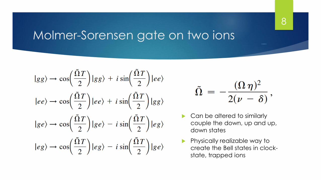
Molmer-Sorensen gate on two ions
Can be altered to similarly
couple the down, up and up,
down states
Physically realizable way to
create the Bell states in clock-
state, trapped ions
8
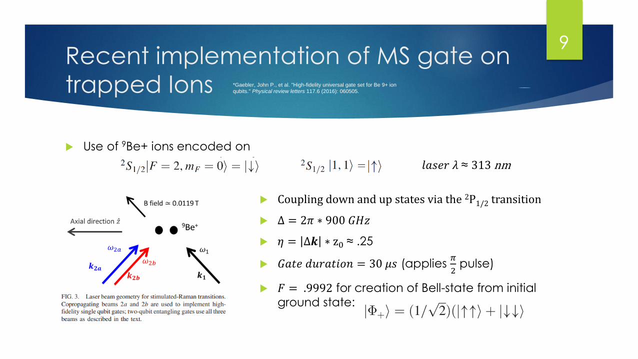
Recent implementation of MS gate on
trapped Ions
Use of 9Be+ ions encoded on
*Gaebler, John P., et al. "High-fidelity universal gate set for Be 9+ ion
qubits." Physical review letters 117.6 (2016): 060505.
Coupling down and up states via the 2P1/2 transition
Δ = 2𝜋 ∗ 900 𝐺𝐻𝑧
𝜂 = Δ𝒌 ∗ z0 ≈ .25
𝐺𝑎𝑡𝑒 𝑑𝑢𝑟𝑎𝑡𝑖𝑜𝑛 = 30 𝜇𝑠 (applies 𝜋
2pulse)
𝐹 = .9992 for creation of Bell-state from initial
ground state:
𝑙𝑎𝑠𝑒𝑟 𝜆 ≈ 313 nm
9
Drawbacks of the MS-gate
Large detunings (~GHz) can be difficult to access and control reliably
Gates very sensitive to optical field phase, easily leads to decoherence if
not controlled precisely as shown by Lee et al.
Optical transitions in the UV (313nm) can be difficult and/or expensive to
reliably create and control over a variety of platforms (ex, atom chips and
optical fibers)
Light-Shift gates can potentially avoid these issues if implementation on
clock-state qubits is possible!
Lee, Patricia J., et al. "Phase control of trapped ion quantum gates." Journal of Optics B: Quantum and Semiclassical Optics 7.10
(2005): S371.
10
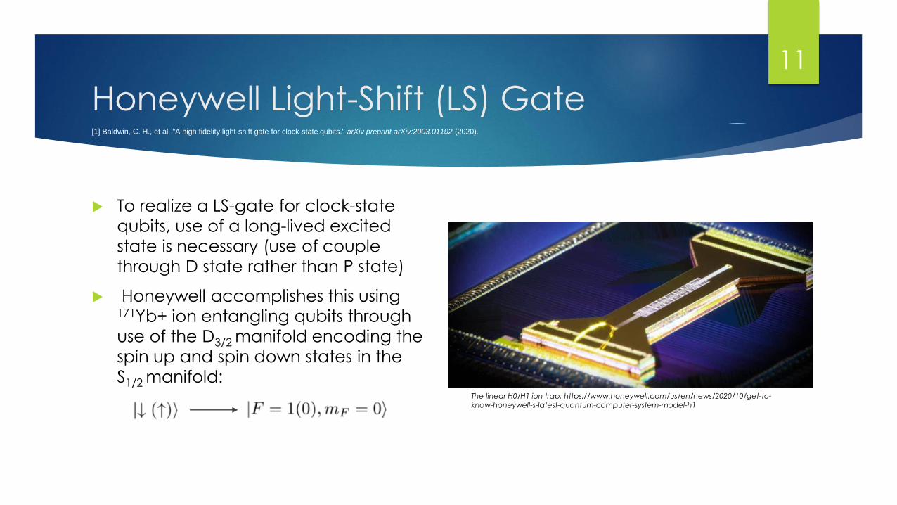
Honeywell Light-Shift (LS) Gate
To realize a LS-gate for clock-state
qubits, use of a long-lived excited
state is necessary (use of couple
through D state rather than P state)
Honeywell accomplishes this using 171Yb+ ion entangling qubits through
use of the D3/2 manifold encoding the
spin up and spin down states in the
S1/2 manifold:The linear H0/H1 ion trap; https://www.honeywell.com/us/en/news/2020/10/get-to-
know-honeywell-s-latest-quantum-computer-system-model-h1
[1] Baldwin, C. H., et al. "A high fidelity light-shift gate for clock-state qubits." arXiv preprint arXiv:2003.01102 (2020).
11
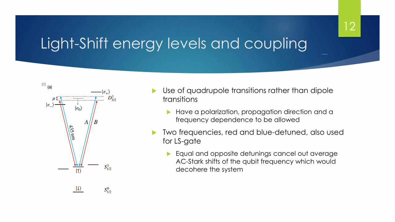
Light-Shift energy levels and coupling
Use of quadrupole transitions rather than dipole
transitions
Have a polarization, propagation direction and a
frequency dependence to be allowed
Two frequencies, red and blue-detuned, also used
for LS-gate
Equal and opposite detunings cancel out average
AC-Stark shifts of the qubit frequency which would
decohere the system
[1]
12
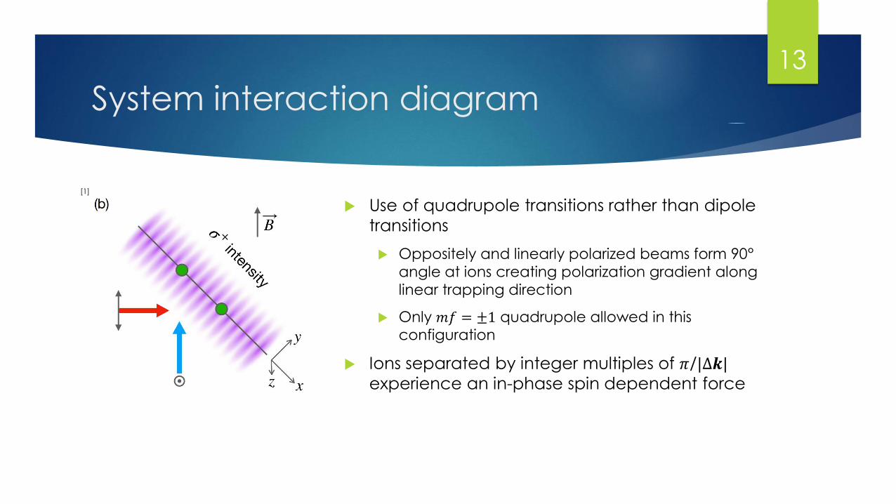
System interaction diagram
Use of quadrupole transitions rather than dipole
transitions
Oppositely and linearly polarized beams form 90°
angle at ions creating polarization gradient along
linear trapping direction
Only 𝑚𝑓 = ±1 quadrupole allowed in this
configuration
Ions separated by integer multiples of 𝜋/|Δ𝒌|experience an in-phase spin dependent force
[1]
13
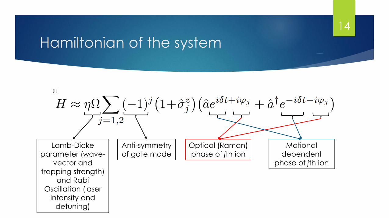
Hamiltonian of the system
Lamb-Dicke
parameter (wave-
vector and
trapping strength)
and Rabi
Oscillation (laser
intensity and
detuning)
Anti-symmetry
of gate mode
Optical (Raman)
phase of jth ion
Motional
dependent
phase of jth ion
[1]
14
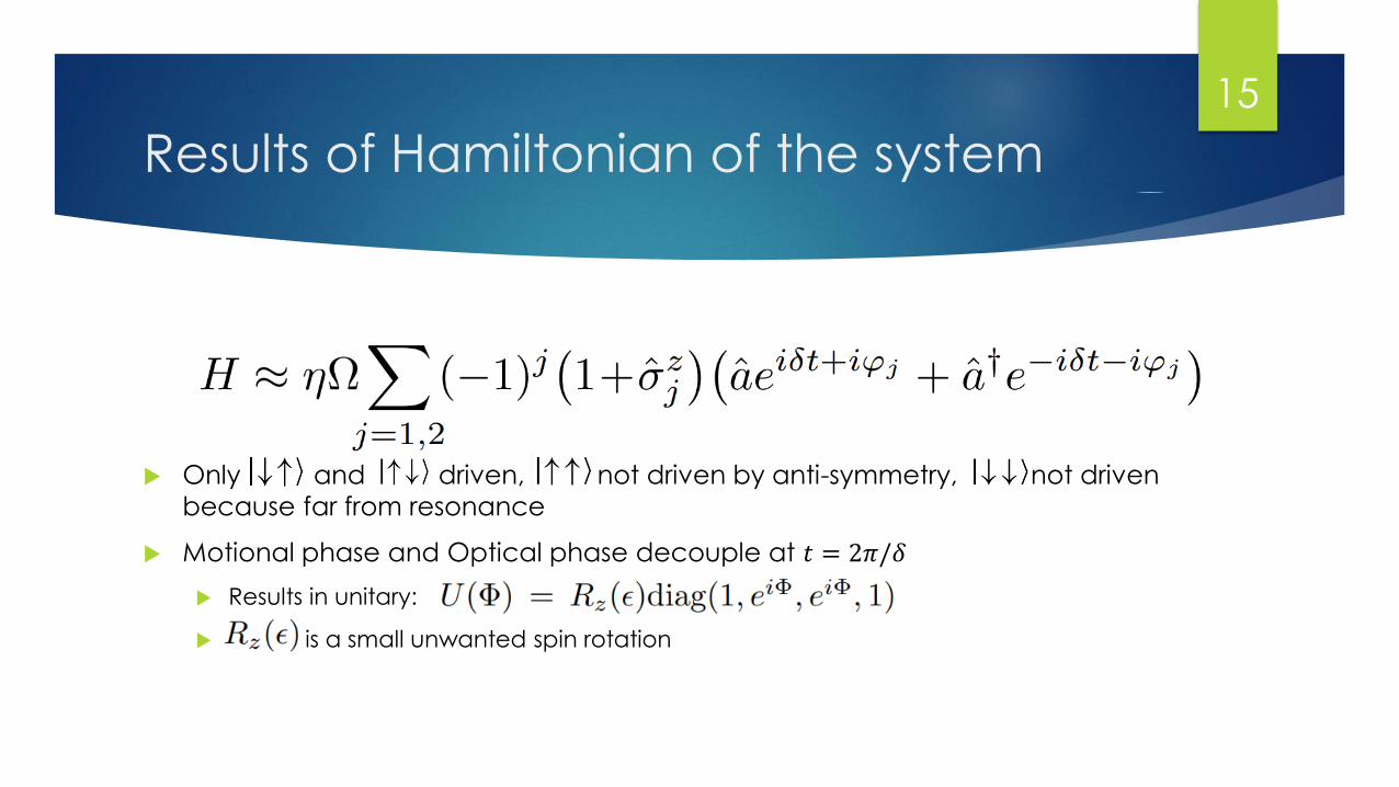
Results of Hamiltonian of the system
Only and driven, not driven by anti-symmetry, not driven
because far from resonance
Motional phase and Optical phase decouple at 𝑡 = 2𝜋/𝛿
Results in unitary:
is a small unwanted spin rotation
15
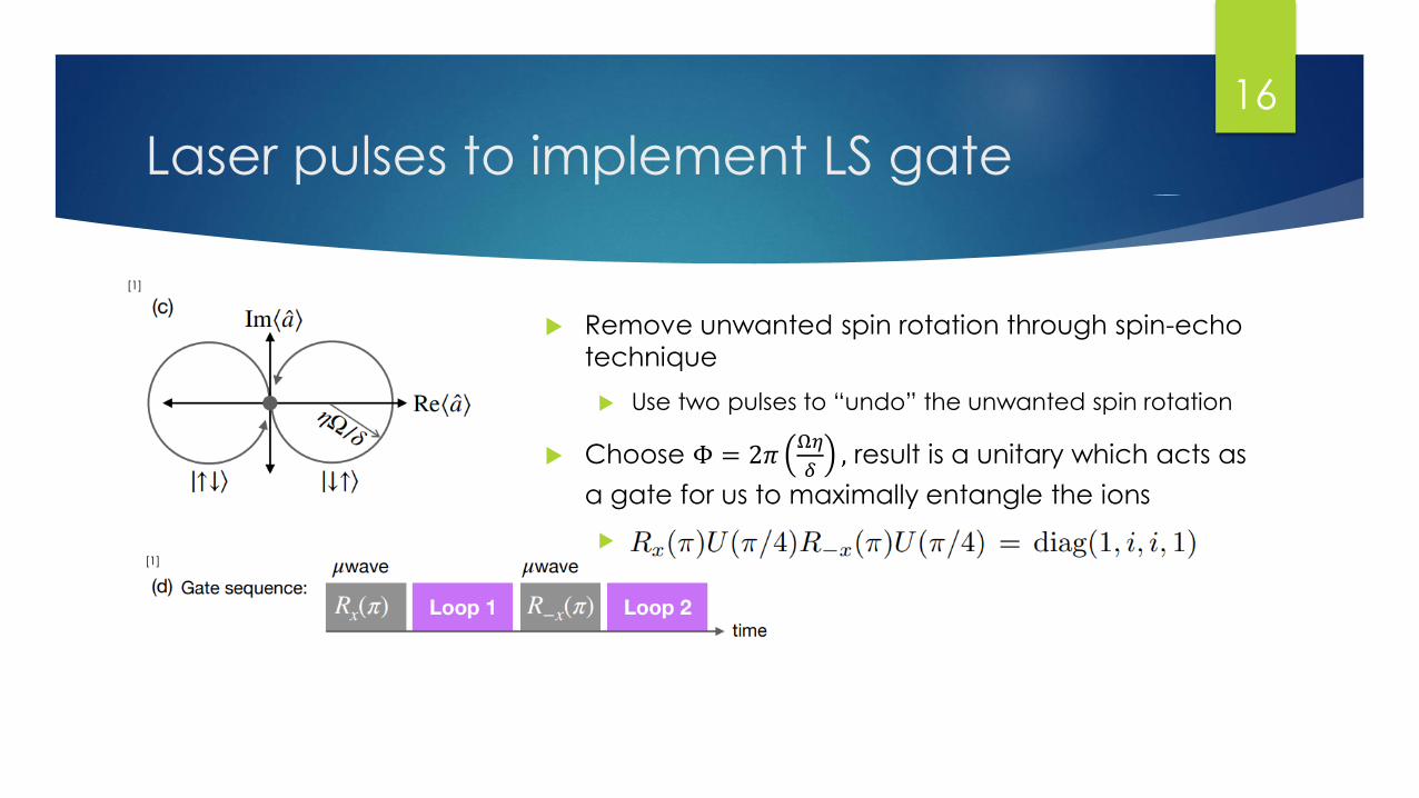
Laser pulses to implement LS gate
Remove unwanted spin rotation through spin-echo
technique
Use two pulses to “undo” the unwanted spin rotation
Choose Φ = 2𝜋Ω𝜂
𝛿, result is a unitary which acts as
a gate for us to maximally entangle the ions
[1]
[1]
16
Measuring Fidelity
The LS gate together with arbitrary, global rotations give access to a two-
qubit subspace spanned by { , ( + )/ 2), }
Such rotations can be implemented by microwaves
Using this method Honeywell estimated fidelity by using their subspace
randomized benchmarking protocol with a 𝐹 = .9974 [1]
Note: this is not yet a universal gate set
17
Quantifying sources of error
Technical sources of error include
Polarization imperfections – residual population in D states at end of gate due
to small coupling of up-state to 𝑚𝑓 = 0 excited state
Laser intensity variability – fluctuations in laser power can lead to AC-Stark shifts
that are not perfectly canceled by the spin-echo
Non-technical sources of error
Deviations from Lamb-Dicke regime
Spontaneous emission
Failures of the rotating wave approximation
18
Maximum theoretical fidelities and
needed improvements
Using ideal calculated pulse shapes, detunings and powers, non-
technical sources of error reveal an attainable fidelity of greater than
.9999
With 𝐹 = .9974, it is assumed technical errors dominate the error in the LS
gate and can thus be improved with modest improvements to
parameters such as trap noise, laser line width, laser power stability,
polarization purity, ect.
The LS gate is not yet universal which will be needed for its use in future
quantum computing designs
19

Questions
20
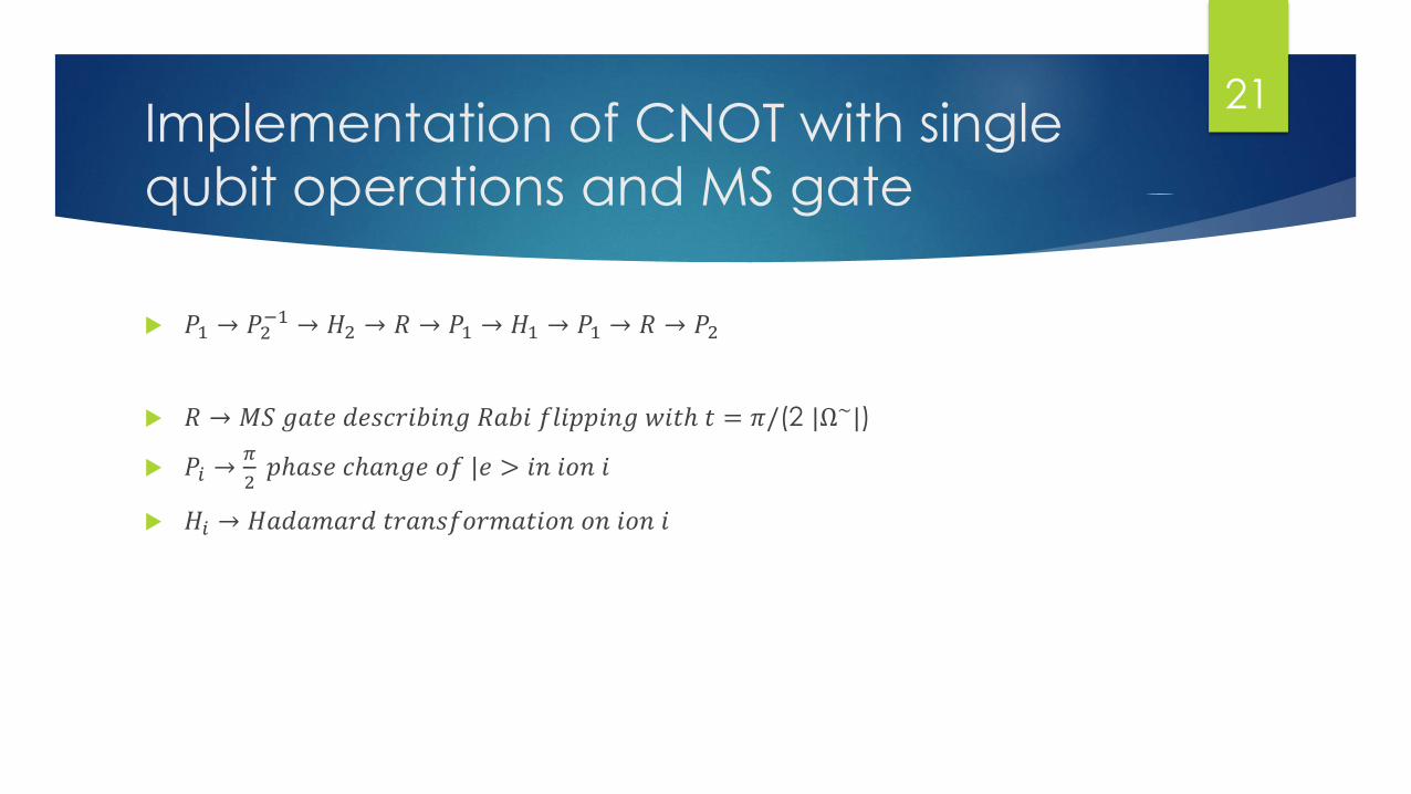
Implementation of CNOT with single
qubit operations and MS gate
𝑃1 → 𝑃2−1 → 𝐻2 → 𝑅 → 𝑃1 → 𝐻1 → 𝑃1 → 𝑅 → 𝑃2
𝑅 → 𝑀𝑆 𝑔𝑎𝑡𝑒 𝑑𝑒𝑠𝑐𝑟𝑖𝑏𝑖𝑛𝑔 𝑅𝑎𝑏𝑖 𝑓𝑙𝑖𝑝𝑝𝑖𝑛𝑔 𝑤𝑖𝑡ℎ 𝑡 = 𝜋/(2 |Ω~|)
𝑃𝑖 →𝜋
2𝑝ℎ𝑎𝑠𝑒 𝑐ℎ𝑎𝑛𝑔𝑒 𝑜𝑓 |𝑒 > 𝑖𝑛 𝑖𝑜𝑛 𝑖
𝐻𝑖 → 𝐻𝑎𝑑𝑎𝑚𝑎𝑟𝑑 𝑡𝑟𝑎𝑛𝑠𝑓𝑜𝑟𝑚𝑎𝑡𝑖𝑜𝑛 𝑜𝑛 𝑖𝑜𝑛 𝑖
21
Sources
Baldwin, C. H., et al. "A high fidelity light-shift gate for clock-state qubits." arXiv
preprint arXiv:2003.01102 (2020).
Gaebler, John P., et al. "High-fidelity universal gate set for Be 9+ ion
qubits." Physical review letters 117.6 (2016): 060505.
Sørensen, Anders, and Klaus Mølmer. "Quantum computation with ions in
thermal motion." Physical review letters 82.9 (1999): 1971.
Roos, Christian F. "Ion trap quantum gates with amplitude-modulated laser
beams." New Journal of Physics 10.1 (2008): 013002.
22