Embed Size (px)
Citation preview

1
SEMICON® Japan 2006
Overview ofSEMI F47-0706
Chuck Thomas
Senior Engineer
Semiconductor & Industrial PQ ServicesEPRI
942 Corridor Park BlvdKnoxville, TN 37932W:+001.865.218.8031M: [email protected]
www.f47testing.com
2
SEMICON® Japan 2006
Why Change SEMI F47?
• The original SEMI F47-0200 (voltage sag immunity) was found to be highly successful in reducing service costs and increasing tool reliability and uptime.
• Since 2000, Semiconductor Manufacturers, Tool Suppliers and Compliance Testing Companies have amassed a significant technical and practical knowledge base related to testing. This information is beneficial to incorporate in the revised standard.
• Where Practical, more closely harmonize with new Standards such as IEC 61000-4-11 and IEC 61000-4-34.

3
SEMICON® Japan 2006
What Changed?
• Removal of 50ms, 50% Vnom Test Point.
• Referencing of Test Durations are now presented only in Cycles – with specific values for 50 and 60 Hz.
• Equipment must now pass at the test point levels rather than “above the defined line”
• Compliance with the new SEMI F47-0706 is defined by passing three test points rather than compliance to a “Curve” as defined in SEMI F47-0200.– (Use of Implied Curve is still valid for comparing against PQ
Data)

4
SEMICON® Japan 2006
What Changed?• Test Vectors are Defined – Original SEMI F47-0200 left
this information implied.– Single-Phase Test Vectors are the Same– Three Methods of Allowable Phase-to-Phase Test Vectors are
allowed
• Pass/Fail Criteria is broken out now for Tooling Equipment and Subsystems– Tools – Still use Interrupt Criteria– Subsystems – Have Three Classes of Responses
• Specific Requirements of Certification Documents are Defined
• A Significant Related Information Section aids the reader in a more in-depth understanding of intent

5
SEMICON® Japan 2006
What Changed?
• Addition of Section addressing how to use the specification for Procurement of tools, subsystems and components that are compliant to SEMI F47-0706.
• Standard Specifically states that three-phase sags not required.

6
SEMICON® Japan 2006
What Did Not Change?
• The Intent is the same – to lead to tools that are robust to voltage sags through through component selection and design strategies.
• The Pass/Fail Criteria for Tools Did not Change (Based on Previous Interrupt Terminology)
• The basic test levels are the same (except for 50ms test point).
• Terminology is basically the same.

7
SEMICON® Japan 2006
What Happened to SEMI F42-0600?
• SEMI F42-0600 has been superceded by SEMI F47-0706 and IEC 61000-4-34
• The semiconductor tool specific step-by-step approach for tool testing defined in SEMI F42-0600 has been replaced with a more generic test description.
• Individuals who want an in-depth understanding of how to conduct voltage sag testing will need to contact industry experts for guidance. SEMI F42-0600 can still be used as a resource.

8
SEMICON® Japan 2006
An Overview of the New SEMI F47-0706 including
Supplemental Examples and Considerations

9
SEMICON® Japan 2006
1.0 Purpose

10
SEMICON® Japan 2006
1.1 Purpose
– Semiconductor factories require high levels of power quality due to the sensitivity of equipment and process controls.
– Semiconductor processing equipment is especially vulnerable to voltage sags.
– This specification defines the voltage sag immunity required for semiconductor processing, metrology, and automated test equipment.
– This specification strikes a balance between voltage sag immunity and increased equipment cost.
11
SEMICON® Japan 2006
2.0 Scope

12
SEMICON® Japan 2006
2.1 Scope
• This specification sets minimum voltage sag immunity requirements for equipment used in the semiconductor industry.
• Immunity is specified in terms of voltage sag depth (in percent of nominal voltage remaining during the sag) and voltage sag duration (in cycles or seconds).
• This specification also sets procurement requirements, test methods, pass/fail criteria, and test report requirements.

13
SEMICON® Japan 2006
2.2 Scope – Primary Focus
• The primary focus of this specification is semiconductor processing equipment including but not limited to the following types:– Etch equipment (Dry & Wet) – Film deposition equipment (CVD & PVD)– Thermal equipment – Surface prep and clean equipment – Photolithography equipment (Scanner, Stepper & Tracks)– Ion Implant equipment – Metrology equipment – Automated test equipment – Chemical Mechanical Polishing/Planarization equipment

14
SEMICON® Japan 2006
2.2 Scope – Secondary Focus• The secondary focus of this specification is subsystems
and components that are used in the construction of semiconductor processing equipment, including but not limited to:– Power supplies– Radio frequency generators and matching networks– Ultrasonic generators– Computers and communication systems – Robots and factory interfaces– AC Contactor coils and AC relay coils– Chillers and cryo pumps– Pumps and blowers– Adjustable speed drives

15
SEMICON® Japan 2006
2.3 Scope – Application Boundaries
This specification applies to semiconductor processing equipment to include the equipment mainframe and all subsystems whose electrical power is directly affected by the operation of the equipment's EMO (emergency off) system.
16
SEMICON® Japan 2006
2.4 Scope - Grandfather Clause
Equipment, subsystems, and components that were tested or certified under the previous version of this specification, prior to the publication date of this specification, do not require re-testing or re-certification until hardware or software design changes that could affect voltage sag immunity are implemented.

17
SEMICON® Japan 2006
3.0 Limitations (summary)• 3.1. Addresses voltage sags only. If necessary, the Information Technology Industry
Council (ITIC) curve contained in IEEE 1100 and SEMI E51 can be used to specify additional requirements outside the scope of this specification.
• 3.2 Wafer Quality Not Addressed. This specification does not address wafer quality variations that may be caused by voltage sags….
• 3.3 Factory and Utility Not Addressed. See SEMI F49-0200 - Guide for Semiconductor Factory Systems Voltage Sag Immunity and SEMI F50-0200 -Guide for Electric Utility Voltage Sag Performance for Semiconductor Factories
• 3.4….SEMI S2 is for addressing design issues related to safety.
• 3.5… if hazards could result from voltage sags deeper and/or longer than those considered in this specification, provision should be made to negate or eliminate such hazards.
• 3.6 Conflicts between this specification and safety requirements (such as SEMI S2) that cannot be otherwise resolved shall be decided in favor of safety requirements.
• 3.7 This specification does not pre-empt or override international, national, and local codes that may apply in different facility locations.

18
SEMICON® Japan 2006
4.0 Related Standards and Documents
4.1 SEMI Standards • SEMI E51 — Guide for Typical Facilities Services and Termination Matrix • SEMI S2 — Environmental, Health, and Safety Guideline for Semiconductor
Manufacturing Equipment 4.2 IEEE Standards• IEEE 1100 — IEEE Recommended Practice for Powering and Grounding Sensitive
Electronic Equipment (IEEE Emerald Book) • IEEE 1250 — IEEE Guide for Service to Equipment Sensitive to Momentary Voltage
Disturbances 4.3 IEC Standards• IEC 61000-4-11 — Testing and Measurement Techniques — Voltage Dips, Short
Interruptions and Voltage Variations Immunity Tests (for equipment rated at 16 amps per phase or less)
• IEC 61000-4-34 — Testing and Measurement Techniques — Voltage Dips, Short Interruptions and Voltage Variations Immunity Tests for Equipment with Input Current more than 16 A per Phase.

19
SEMICON® Japan 2006
5.0 Terminology• 5.1 assist — a response to an unplanned stoppage that occurs during an equipment
cycle in which all three of the following conditions apply:
– The stopped equipment cycle is resumed through external intervention (e.g. by an operator or user), and
– There is no replacement of a part, other than specified consumables, and – There is no further variation from specification of equipment operation
• 5.2 failure — any unplanned stoppage or variance from the specification of equipment operations other than assists
• 5.3 interrupt — any equipment assist or equipment failure • 5.4 voltage sag immunity — the ability of equipment to withstand momentary
electric power interruptions or sags [IEEE 1250 ride-through capability]. • 5.5 voltage sag — an rms reduction in the ac voltage, at the power frequency, for
durations from a half cycle to a few seconds. [IEEE 1100] Note: The IEC terminology for this phenomenon is voltage dip

20
SEMICON® Japan 2006
6.0 Use of Specification for Procurement
• (6.1) Defines how to use standard to specify voltage sag requirements.
• (6.2) Defines how orders for compliant semiconductor equipment should specify the requirement for certificates (per section 7.9) or test reports (per section 7.10) and requirementsrelated to self or third-party certification
• (6.3) Defines how orders for compliant subsystems and components should be specified regarding the pass/fail criteria (see paragraph 7.8.2 and R1-6), requirements for tests report, self or third-part certification.

21
SEMICON® Japan 2006
7.0 Requirements

22
SEMICON® Japan 2006
7.1 Requirements
• Required voltage sag immunity — Semiconductor processing equipment, subsystems, and components are required to be immune to the voltage sag levels and durations set forth in Table 1.
[#1] Sag depth is expressed in percent of remaining nominal voltage. For example, during a 70% sag on a 200 volt nominal system, the voltage is reduced during the sag to 140 volts (not 60 volts).

23
SEMICON® Japan 2006
Visualization of Standard
Disturbance DataAll Semiconductor Sites
0%
10%
20%
30%
40%
50%
60%
70%
80%
90%
100%
110%
1 10 100 1000Duration (cycles)
Perc
ent o
f Nom
inal
Vol
tage
Required Voltage Sag Immunity
Test Points (From Table 1)
Recommended VoltageSag Immunity Test Points
(From Table R1-1)

24
SEMICON® Japan 2006
7.2 Sag immunity test methods
• Semiconductor processing equipment, subsystems, and components shall be tested for voltage sag immunity according to the methods set forth in IEC 61000-4-11 (for equipment rated at 16 amps per phase or less) or IEC 61000-4-34 (for equipment rated at more than 16 amps per phase). The test levels in Table 1 above replace the "Class X" levels in Table 1 of IEC 61000-4-11 and IEC 61000-4-34.
• NOTE 4: For the purposes of SEMI F47, creating phase-to-phase sags by simultaneously reducing the phase-to-neutral voltage an equal amount on two phases is permitted (i.e. the test vectors of IEC 61000-4-34 Fig 3d are permitted).

25
SEMICON® Japan 2006
7.2 Phase-to-neutral testing on 3-Phase Systems
• Phase-to-neutral testing on three-phase systems is performed one phase at a time.
A – Phase-to-neutral testing on three-phase systems
26
SEMICON® Japan 2006
7.2 Phase-to-PhaseTesting Options
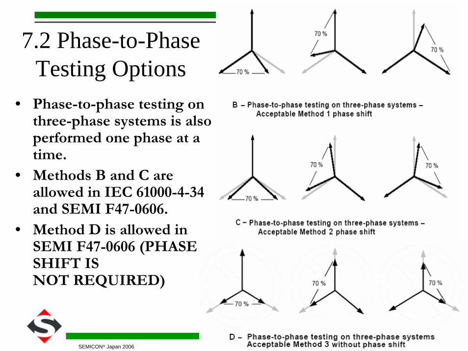
• Phase-to-phase testing on three-phase systems is also performed one phase at a time.
• Methods B and C are allowed in IEC 61000-4-34 and SEMI F47-0606.
• Method D is allowed in SEMI F47-0606 (PHASE SHIFT ISNOT REQUIRED)

27
SEMICON® Japan 2006
7.3 Owner notification
• As with other equipment tests, damage to the EUT (Equipment Under Test) is possible.
• Although only a remotepossibility, the engineer performing the test should notify the equipment owner of the potential for damage prior to initiating the test.

28
SEMICON® Japan 2006
7.4 Three-phase sags not required
• Test sags shall be applied to one phase-to-neutral pair at a time, if a neutral conductor is present, and to one phase-to-phase pair at a time.
• Simultaneous sags on all six phase-to-neutral pairs and phase-to-phase pairs are not required, and simultaneous sags on all three phase-to-phase pairs are not require

29
SEMICON® Japan 2006
Sections 7.5-7.6 • 7.5 Selecting EUT for voltage sag testing
– 7.5.1 Sample test — Test on sample only…does not need not be performed on each equivalent article produced.
– 7.5.2 Test results should apply to multiple models or types (based on engineering judgment)
• 7.6 If semiconductor processing equipment has multiple chambers,it is acceptable to test and certify each chamber independently.– The common portion of the system (mainframe) must be tested as
well.– The semiconductor processing equipment manufacturer must exercise
reasonable engineering judgment regarding potential interactionsbetween multiple chamber configurations and the mainframe duringvoltage sags.
– NOTE 6: It is the intent of this clause to simplify the testing and certification of equipment that can be configured with a variety of chamber combinations.

30
SEMICON® Japan 2006
7.7 Test conditions• The intent of this specification is to make reasonable efforts at
determining that semiconductor processing equipment, subsystems,and components will be immune to typical voltage sags that occur at semiconductor factories.
• The EUT shall be tested for voltage sag immunity under conditions that will, according to the reasonable engineering judgment of the equipment manufacturer, approximate expected factory operating conditions. Engineering judgment shall take into account the following considerations: – The EUT shall be tested in its most sensitive process states, as
determined by the EUT manufacturer. For example, this may include robot movement, maximum power processing, most sensitive measurement, etc. If the sensitivity of the EUT to voltage sags may be affected by process recipe, the EUT shall be tested with a baseline recipe as defined in SEMI S2.
– Components, and subsystems when tested independently shall be tested under load (for example, DC power supplies and RF generators should be loaded at their expected levels, chillers and cryos should be thermally loaded, etc.)

31
SEMICON® Japan 2006
7.8 Pass/fail criteria

32
SEMICON® Japan 2006
7.8.1 Pass/fail criteria for equipment• In the absence of other instructions or requirements, the pass/fail
criteria for voltage sag immunity testing of semiconductor processing equipment shall be no interrupts, as defined in ¶5.3.
• 5.1 assist — a response to an unplanned stoppage that occurs during an equipment cycle in which all three of the following conditions apply: – The stopped equipment cycle is resumed through external
intervention (e.g. by an operator or user), and – There is no replacement of a part, other than specified
consumables, and – There is no further variation from specification of equipment
operation
• 5.2 failure — any unplanned stoppage or variance from the specification of equipment operations other than assists
• 5.3 interrupt — any equipment assist or equipment failure
33
SEMICON® Japan 2006
7.8.2 Pass/fail criteria for subsystems and components
• Voltage sag immunity testing of subsystems and components should meet one of the following: a) Performs at full rated operation b) May not perform at full rated operation but recovers
operation without operator and/or host controller intervention. Must not send error signals to the equipment host controller indicating when full rated operation is not achieved.
c) May not perform at full rated operation but recovers operation without operator and/or host controller intervention. May send signals to the equipment host controller indicating when full rated operation is not achieved.

34
SEMICON® Japan 2006
7.8.2 Pass/fail criteria for subsystems and components – Criteria A Example(Performs at full rated operation )
• 12 Cycle, 50% VnominalVoltage Sag
• 24Vdc Power Supply Output Remains Constant (Full Rated Operation)

35
SEMICON® Japan 2006
7.8.2 Pass/fail criteria for subsystems and components –Criteria B/C Example
(Does not Perform at full rated operation )• Criteria B –May not perform at full
rated operation but recovers operation without operator and/or host controller intervention. Must not send error signals to the equipment host controller indicating when full rated operation is not achieved.
• Criteria C - Same as B but may send signals to the equipment host controller indicating when full rated operation is not achieved.
• B or C - performance can hinge on if an error signal is sent to the host controller.
• In some cases Criteria C could be desired over Criteria B.
(Application Dependant )

36
SEMICON® Japan 2006
7.9-7.10 Certificates and Reports (Requirements)
7.9 Defines Requirements for Certificates
7.10 Defines Requirements for Reports

37
SEMICON® Japan 2006
Related Information
NOTICE: This related information is not an official part of SEMI F47 and does not modify or
supersede the official specification.
Determination of the suitability of the material is solely the responsibility of the user.

38
SEMICON® Japan 2006
Related Info Sections• R1-1 Typical Waveforms
• R1-2 Some Common Mistakes
• R1-3 Equipment not Immune to all real world voltage sags
• R1-4 Recommended Voltage Sag Immunity
• R1-5 Preferred Voltage Sag Immunity Solutions
• R1-6 Choosing Pass/Fail Criteria for Subsystems and Components
• R1-7 Currents During and After Sags
• R1-8 Impact of Voltage Sags on Equipment
• R1-9 Test Plan
• R1-10 Characterization vs. Pass/Fail Testing