Embed Size (px)
Citation preview
OWNER'SHANDBOOK
MINI COUNTRYMAN


ONECooper
Cooper SCooper S ALL4
One DCOOPER D
Cooper D All4Cooper SD
Cooper SD All4
Congratulations on your new MINI

© 2011 Bayerische Motoren WerkeAktiengesellschaftMunich, GermanyNot to be reproduced, wholly or in part, withoutwritten permission from BMW AG, Munich.English II/11 Printed on environmentally friendly paper,bleached without chlorine, suitable for recycling.
CONTENTS
The quickest access to a particular topic or item is by consulting the detailed alphabetical index, see page 198.
Notes4 General information
OVERVIEW8 Driving area14 Radio MINI CD15 Radio MINI Boost CD
CONTROLS20 Opening and closing32 Adjusting40 Child safety46 Driving58 Everything under control68 Technical features for driving comfort
and safety76 Lights82 Climate87 Practical interior equipment
DRIVING HINTS92 Driving precautions
Entertainment108 Radio MINI CD114 Radio MINI Boost CD
COMMUNICATION126 Telephone
MOBILITY140 Refuelling142 Wheels and tyres146 In the engine compartment151 Maintenance153 General care157 Replacing parts168 Mutual aid172 Indicator and warning lights
REFERENCE186 Technical data193 Maintenance overview198 From A to Z
Notes General information
4
General information
About this Owner's HandbookWe have tried to make all the information in this Owner's Handbook easy to find. The quickest way to access a specific topic or item is by con-sulting the detailed alphabetical index at the end. Consult the first chapter for an overview of your car.
When the time comes to sell your MINI, remem-ber to hand over this Owner's Handbook; it is an important part of the vehicle.
Additional sources of informationIf you have any queries, your MINI Service Cen-tre will be glad to advise you.
You can find additional MINI-related informa-tion, for example on the engineering features, in the Internet by visiting www.MINI.com.
Symbols usedIndicates precautions that must be fol-lowed precisely in order to avoid the pos-
sibility of personal injury and serious damage to the vehicle.<
Indicates information that will assist you in gaining the optimum benefit from your
vehicle and enable you to care more effectively for your vehicle.<
Refers to measures that can be taken to help protect the environment.<
< Marks the end of a specific item of informa-tion.
* Identifies optional extras or specific national-market items of equipment, as well as equip-ment and functions not yet available at the time of printing.
Symbol for components and assembliesRecommends that you study the relevant section of this Owner's Handbook in con-
nection with a particular part or assembly.
Your carYour MINI is manufactured by Bayerische Motoren Werke Aktiengesellschaft, BMW AG.
When you ordered your MINI, you chose various items of equipment. This Owner's Handbook describes all models and equipment specifica-tions which the manufacturer of your MINI offers within this particular model line.
This explains why the Owner's Handbook may also contain details of items which you have not ordered. The differences can easily be identified by the asterisk * shown against optional extras.
If your MINI features equipment not described in this Owner's Handbook, observe the enclosed Supplementary Owner's Handbooks.
In vehicles with right-hand drive, some of the controls are arranged differently from
those shown in the illustrations of this Owner's Handbook.<
Built-date*The production date of your vehicle can be found at the bottom of the door column of the driver door.
The 'built-date' is defined as 'the calendar month and the calendar year in which the body shell and the powertrain subassemblies are con-joined and the vehicle is driven or moved from the production line'.
General information Notes
5
Status at time of printingThe high safety and quality standards of MINI vehicles are guaranteed by continuous develop-ment. In rare instances, your vehicle may there-fore differ from the information supplied in the Owner's Handbook.
For your safetyYour vehicle is configured for the operating con-ditions and registration requirements of your country. If the vehicle is to be operated in another country, your vehicle must be adapted to any prevailing different operating conditions and permit requirements.Information on possible exclusion of warranty or warranty restrictions for your vehicle can be obtained from your MINI Service Centre.
For customers in Australia/New ZealandAs you read this manual, please bear the follow-ing in mind: to ensure that our vehicles continue to embody the highest quality and safety stand-ards, we at MINI pursue a policy of continuous, ongoing development. Because modifications in the design of both vehicles and accessories may be introduced at any time, your own vehicle's equipment may vary from that described in this manual. For the same reason, it is also impossi-ble to guarantee that all descriptions will be completely accurate in all respects.
We must therefore request your understanding of the fact that we are unable to recognise legal claims based on discrepancies between the data, illustrations and descriptions in this man-ual and your own vehicle's equipment. Please note, too, that some of the optional equipment described in this manual is not available on Aus-tralian models due to restrictions imposed by Australian Design Rules and other requirements.
If you have any queries, your Service Centre will be glad to advise you.
For your safety
Maintenance and repairThe advanced technology behind this vehicle, for example the use of modern
materials and high-performance electronics, means that specially adapted methods of main-tenance and repair are required. You should therefore have the work this involves carried out only by a MINI Service Centre or a workshop employing trained personnel and working to the specifications issued by the manufacturer of your MINI. If such work is performed inexpertly, it could result in consequential damage and thus constitute a safety risk.<
Parts and accessoriesThe manufacturer of your MINI recommends using parts and accessory
products for the car which the manufacturer of your MINI has approved for this purpose. MINI Service is the correct source for genuine MINI parts and accessories, other products approved by the manufacturer of your MINI, and competent advice on all related matters. These parts and products have been tested by the manufacturer of your MINI for their safety and functional compatibility with MINI vehicles. The manufacturer of your MINI accepts product liability for them. Conversely, the manufacturer of your MINI can-not accept liability for parts or accessory prod-ucts of any kind which it has not approved. The manufacturer of your MINI is unable to assess each individual product of outside origin as to its suitability for use on MINI vehicles with-out safety risk. This suitability cannot be guaran-teed even if an official permit has been issued for the particular product in a specific country. Tests performed for such permits cannot always cover all operating conditions for MINI vehicles, and some of them therefore are insufficient.<

Watch Me.
CONTROLS
DRIVING HINTS
Entertainment
COMMUNICATION
MOBILITY
REFERENCE
OVERVIEW
OVERVIEW Driving area
8
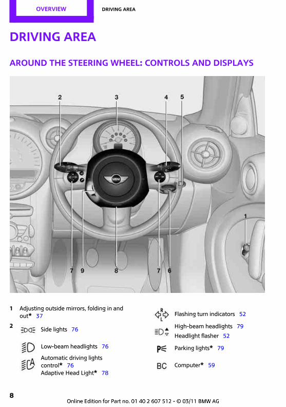
Driving area
Around the steering wheel: Controls and displays
1 Adjusting outside mirrors, folding in and out* 37
2 Side lights 76
Low-beam headlights 76
Automatic driving lights control* 76Adaptive Head Light* 78
Flashing turn indicators 52
High-beam headlights 79
Headlight flasher 52
Parking lights* 79
Computer* 59
Driving area OVERVIEW
9
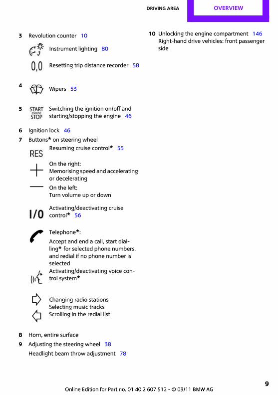
6 Ignition lock 46
7 Buttons* on steering wheel
8 Horn, entire surface
9 Adjusting the steering wheel 38
Headlight beam throw adjustment 78
10 Unlocking the engine compartment 146Right-hand drive vehicles: front passenger side
3 Revolution counter 10
Instrument lighting 80
Resetting trip distance recorder 58
4 Wipers 53
5 Switching the ignition on/off and starting/stopping the engine 46
Resuming cruise control* 55
On the right:Memorising speed and accelerating or decelerating
On the left:Turn volume up or down
Activating/deactivating cruise control* 56
Telephone*:
Accept and end a call, start dial-ling* for selected phone numbers, and redial if no phone number is selected Activating/deactivating voice con-trol system*
Changing radio stationsSelecting music tracksScrolling in the redial list
OVERVIEW Driving area
10
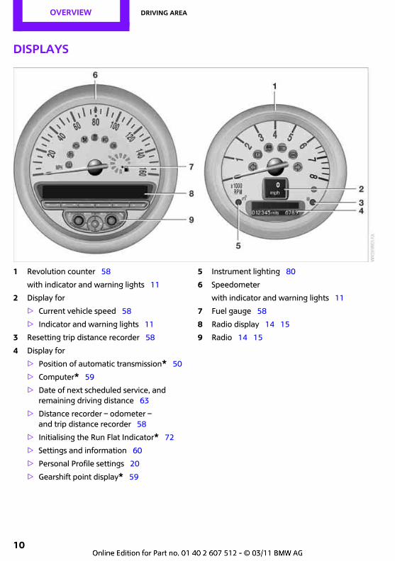
Displays
1 Revolution counter 58
with indicator and warning lights 11
2 Display for
> Current vehicle speed 58
> Indicator and warning lights 11
3 Resetting trip distance recorder 58
4 Display for
> Position of automatic transmission* 50
> Computer* 59
> Date of next scheduled service, and remaining driving distance 63
> Distance recorder – odometer – and trip distance recorder 58
> Initialising the Run Flat Indicator* 72
> Settings and information 60
> Personal Profile settings 20
> Gearshift point display* 59
5 Instrument lighting 80
6 Speedometer
with indicator and warning lights 11
7 Fuel gauge 58
8 Radio display 14 15
9 Radio 14 15
Driving area OVERVIEW
11
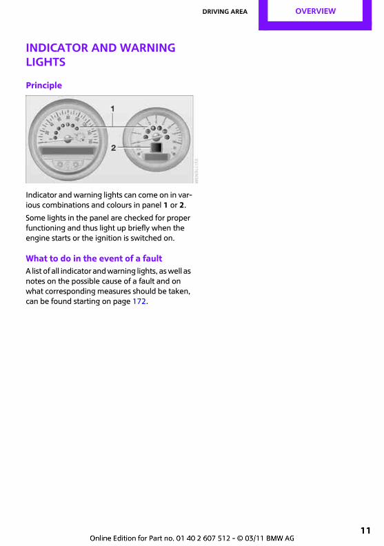
Indicator and warning lights
Principle
Indicator and warning lights can come on in var-ious combinations and colours in panel 1 or 2.
Some lights in the panel are checked for proper functioning and thus light up briefly when the engine starts or the ignition is switched on.
What to do in the event of a faultA list of all indicator and warning lights, as well as notes on the possible cause of a fault and on what corresponding measures should be taken, can be found starting on page 172.
OVERVIEW Driving area
12
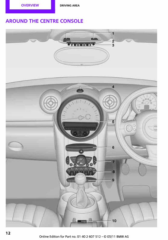
Around the centre console
Driving area OVERVIEW
13
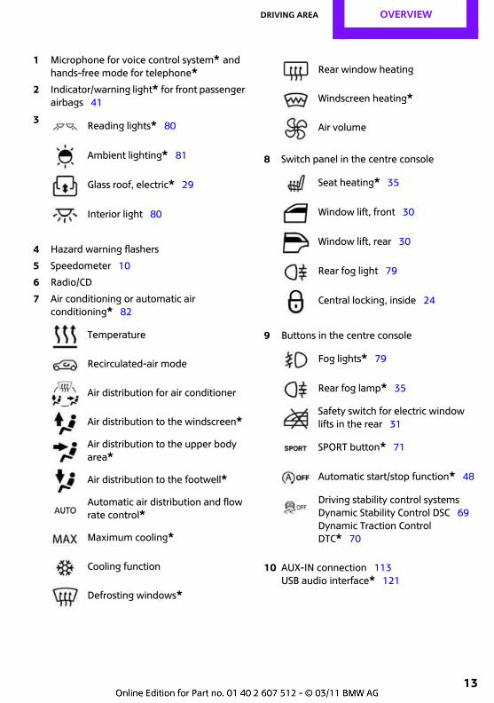
1 Microphone for voice control system* and hands-free mode for telephone*
2 Indicator/warning light* for front passenger airbags 41
4 Hazard warning flashers
5 Speedometer 10
6 Radio/CD
7 Air conditioning or automatic air conditioning* 82
8 Switch panel in the centre console
9 Buttons in the centre console
10 AUX-IN connection 113USB audio interface* 121
3 Reading lights* 80
Ambient lighting* 81
Glass roof, electric* 29
Interior light 80
Temperature
Recirculated-air mode
Air distribution for air conditioner
Air distribution to the windscreen*
Air distribution to the upper body area*
Air distribution to the footwell*
Automatic air distribution and flow rate control*
Maximum cooling*
Cooling function
Defrosting windows*
Rear window heating
Windscreen heating*
Air volume
Seat heating* 35
Window lift, front 30
Window lift, rear 30
Rear fog light 79
Central locking, inside 24
Fog lights* 79
Rear fog lamp* 35
Safety switch for electric window lifts in the rear 31
SPORT button* 71
Automatic start/stop function* 48
Driving stability control systemsDynamic Stability Control DSC 69Dynamic Traction Control DTC* 70
OVERVIEW Radio MINI CD
14
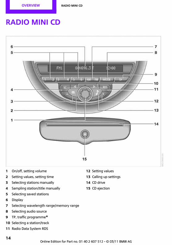
Radio MINI CD
1 On/off, setting volume
2 Setting values, setting time
3 Selecting stations manually
4 Sampling station/title manually
5 Selecting saved stations
6 Display
7 Selecting wavelength range/memory range
8 Selecting audio source
9 TP, traffic programme*10 Selecting a station/track
11 Radio Data System RDS
12 Setting values
13 Calling up settings
14 CD drive
15 CD ejection
Radio MINI Boost CD OVERVIEW
15
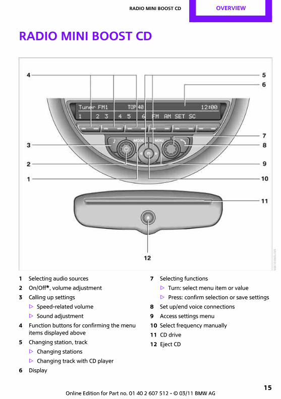
Radio MINI Boost CD
1 Selecting audio sources
2 On/Off*, volume adjustment
3 Calling up settings
> Speed-related volume
> Sound adjustment
4 Function buttons for confirming the menu items displayed above
5 Changing station, track
> Changing stations
> Changing track with CD player
6 Display
7 Selecting functions
> Turn: select menu item or value
> Press: confirm selection or save settings
8 Set up/end voice connections
9 Access settings menu
10 Select frequency manually
11 CD drive
12 Eject CD
OVERVIEW Radio MINI Boost CD
16
Menu guidanceFunctions of radio and telephone* can be accessed via the buttons on the radio and menus.
Access settings menuPress the MENU button for:
> Settings
> MINI call numbers
> Telephone*
Accessing audio menuPress the MODE button for:
> Radio
> Digital radio*> CD player
> External audio device, e.g. MP3 player
> USB audio interface*
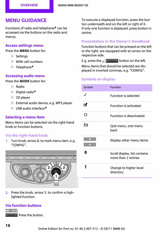
Selecting a menu itemMenu items can be selected via the right-hand knob or function buttons.
Via the right-hand knob1. Turn knob, arrow 2, to mark menu item, e.g.
"CONFIG".
2. Press the knob, arrow 1, to confirm a high-lighted function.
Via function buttons
Press the button.
To execute a displayed function, press the but-ton underneath and on the left or right of it.If only one function is displayed, press button in centre.
Presentation in the Owner's HandbookFunction buttons that can be pressed on the left or the right, are equipped with an arrow on the respective side.
E.g. press the button on the left.
Menu items that should be selected are dis-played in inverted commas, e.g. "CONFIG".
Symbols on display
Symbol Function
Function is selected
Function is activated.
Function is deactivated.
Quit menu, one menu back
Display other menu items
Scroll display, list contains more than 2 entries
Change to higher level directory

Radio MINI Boost CD OVERVIEW
17
Handle Me.
OVERVIEW
DRIVING HINTS
Entertainment
COMMUNICATION
MOBILITY
REFERENCE
CONTROLS
CONTROLS Opening and closing
20
Opening and closing
Key/remote control
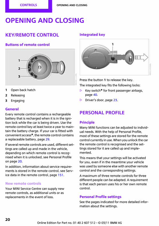
Buttons of remote control
1 Open back hatch
2 Releasing
3 Engaging
GeneralEvery remote control contains a rechargeable battery that is recharged when it is in the igni-tion lock while the car is being driven. Use the remote control key at least twice a year to main-tain the battery charge. If your car is fitted with convenient access*, the remote control contains a replaceable battery, page 29.
If several remote controls are used, different set-tings are called up and made in the vehicle, depending on which remote control is recog-nised when it is unlocked, see Personal Profile on page 20.
In addition, information about service require-ments is stored in the remote control, see Serv-ice data in the remote control, page 151.
New remote controlsYour MINI Service Centre can supply new remote controls, as additional units or as replacements in the event of loss.
Integrated key
Press the button 1 to release the key.
The integrated key fits the following locks:
> Key switch* for front passenger airbags, page 40.
> Driver's door, page 23.
Personal Profile
PrincipleMany MINI functions can be adjusted to individ-ual needs. With the help of Personal Profile, most of these settings are stored for the remote control currently in use. When you unlock the car the remote control is recognised and the set-tings stored for it are called up and imple-mented.
This means that your settings will be activated for you, even if in the meantime your vehicle was used by someone else with another remote control and the corresponding settings.
A maximum of three remote controls for three different people can be adapted. A requirement is that each person uses his or her own remote control.
Personal Profile settingsSee the pages indicated for more detailed infor-mation about the settings.
Opening and closing CONTROLS
21
> Response of the central locking system when the car is unlocked 21
> Automatic locking of the vehicle 25
> Triple turn signal 52
> Settings for the displays in the speedometer and revolution counter:
> 12h/24h mode of the clock, see Formats and units of measure 61
> Date format, see Formats and units of measure 61
> Units of measure for fuel consumption, distance covered/remaining range, and temperature, see Formats and units of measure 61
> Light settings:
> Headlight courtesy delay feature 76
> Daytime driving lights 77
> Automatic air-conditioning system*: acti-vating/deactivating AUTO programme, cool-ing function, adjusting temperature, air flow rate and air distribution 84
> Entertainment:
> Adjusting volume, from page 108
> Adjusting tone, from page 109
Central locking system
The principleThe central locking becomes active when the driver's door is closed.
The following are unlocked or locked in combi-nation:
> Doors
> Tailgate
> Fuel filler flap
Operating from outside> Via the remote control
> Via the door lock*
> With convenient access* by means of the handles on the driver's and the front passen-ger's door
In addition, if the remote control is used, the welcome lights and the interior light are switched on or off. The alarm system* is also armed or disarmed, page 26.
Operating from insideButton for central locking, page 24.
In the event of a sufficiently severe accident, the central locking system unlocks automatically. The hazard warning flashers and the interior light are in addition switched on.
Opening and closing: from the outside
Persons remaining in the vehicle or pets left inside can lock the doors from the
inside. You should therefore take the key with you, so that the car can be opened from the out-side.<
With the remote control
ReleasingPress the button.Welcome lights and interior light come on.
Characteristics during unlockingThe way in which the car is unlocked can also be set. The setting is stored for the remote control in use.
CONTROLS Opening and closing
22
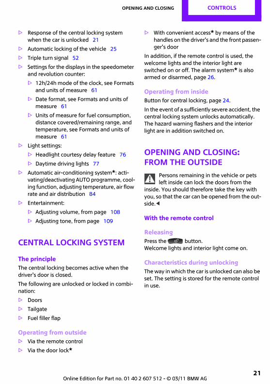
1. Switch on the ignition, see page 46.
2. Press the button in the turn indicator lever repeatedly until "SET/INFO" appears.
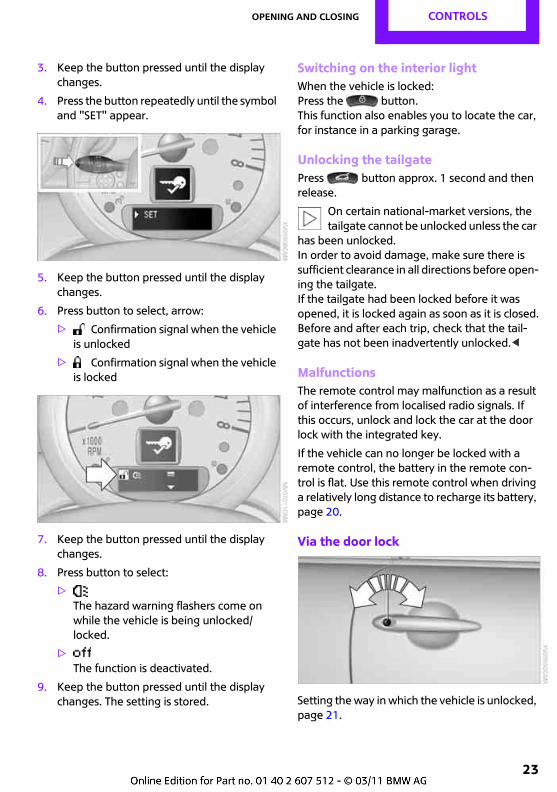
3. Keep the button pressed until the display changes.
4. Press the button repeatedly until the symbol and "SET" appear.
5. Keep the button pressed until the display changes.
6. Press the button repeatedly until the indi-cated symbol, arrow, appears.
7. Keep the button pressed until the display changes.
8. Press button to select:
>Pressing the button only unlocks the driver's door. Press it twice to unlock the entire vehicle.
>Press the button once to unlock the entire vehicle.
9. Keep the button pressed until the display changes. The setting is stored for the remote control currently in use.
Convenient openingHold the button pressed. The electric windows are opened and the glass roof* is raised.
Convenient closing via the remote control is not possible.<
EngagingPress the button.
Do not lock the vehicle from the outside when there is someone inside it, as some
national-market versions as well as versions with certain optional equipment cannot then be unlocked from the inside.<
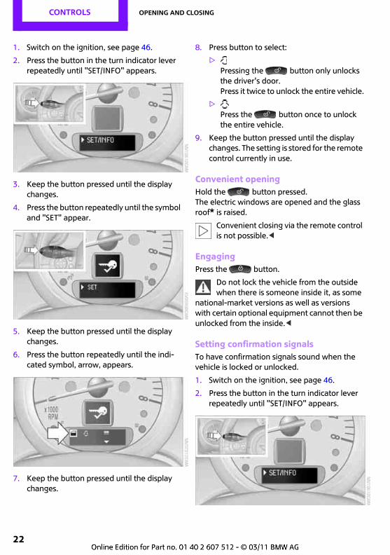
Setting confirmation signalsTo have confirmation signals sound when the vehicle is locked or unlocked.
1. Switch on the ignition, see page 46.
2. Press the button in the turn indicator lever repeatedly until "SET/INFO" appears.
Opening and closing CONTROLS
23
3. Keep the button pressed until the display changes.
4. Press the button repeatedly until the symbol and "SET" appear.
5. Keep the button pressed until the display changes.
6. Press button to select, arrow:
> Confirmation signal when the vehicle is unlocked
> Confirmation signal when the vehicle is locked
7. Keep the button pressed until the display changes.
8. Press button to select:
>The hazard warning flashers come on while the vehicle is being unlocked/locked.
>The function is deactivated.
9. Keep the button pressed until the display changes. The setting is stored.
Switching on the interior lightWhen the vehicle is locked:Press the button. This function also enables you to locate the car, for instance in a parking garage.
Unlocking the tailgatePress button approx. 1 second and then release.
On certain national-market versions, the tailgate cannot be unlocked unless the car
has been unlocked.In order to avoid damage, make sure there is sufficient clearance in all directions before open-ing the tailgate.If the tailgate had been locked before it was opened, it is locked again as soon as it is closed.Before and after each trip, check that the tail-gate has not been inadvertently unlocked.<
MalfunctionsThe remote control may malfunction as a result of interference from localised radio signals. If this occurs, unlock and lock the car at the door lock with the integrated key.
If the vehicle can no longer be locked with a remote control, the battery in the remote con-trol is flat. Use this remote control when driving a relatively long distance to recharge its battery, page 20.
Via the door lock
Setting the way in which the vehicle is unlocked, page 21.
CONTROLS Opening and closing
24
Do not lock the vehicle from the outside when there is someone inside it, as some
national-market versions as well as versions with certain optional equipment cannot then be unlocked from the inside.<
In some national-market versions, the alarm system* is triggered when the car is
unlocked via the door lock.To end the alarm:Unlock the car with the remote control, page 21, or insert the key fully into the ignition lock.<
Alarm system, see page 26.
Without alarm system* or convenient access* only the driver's door is locked via
the door lock.<
To lock all doors, fuel filler flaps and luggage compartment lids together:
> For closed doors with an inside button for central locking in the passenger compart-ment, see page 24, lock the vehicle.
> Unlock and open the driver's side or front passenger door, page 24.
Lock the vehicle.
> Lock the driver's door via the door lock with the integrated key or
> Press down the locking button on the front passenger's door and close the door from outside.
Convenient opening and closingThe alarm system* or convenient access* can be used to operate side window and glass sun-roof* through the door lock.
Opening/closingHold the key in the position for unlocking or locking.
Watch the closing movement to ensure that no one is trapped. The movement is
stopped when the key is released.<
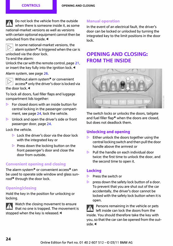
Manual operationIn the event of an electrical fault, the driver's door can be locked or unlocked by turning the integrated key to the limit positions in the door lock.
Opening and closing: from the inside
The switch locks or unlocks the doors, tailgate and fuel filler flap* when the doors are closed, but does not deadlock them.
Unlocking and opening> Either unlock the doors together using the
central locking switch and then pull the door handle above the armrest or
> Pull the handle on each individual door twice: the first time to unlock the door, and the second time to open it.
Locking> Press the switch or
> press down the safety lock button of a door. To prevent that you are shut out of the car accidentally, the driver's door cannot be locked with the safety lock button when it is open.
Persons remaining in the vehicle or pets left inside can lock the doors from the
inside. You should therefore take the key with you, so that the car can be opened from the out-side.<
Opening and closing CONTROLS
25
Automatic locking*The situations in which the vehicle is locked can also be programmed. The setting is stored for the remote control in use.
1. Switch on the ignition, see page 46.
2. Press the button in the turn indicator lever repeatedly until "SET/INFO" appears.
3. Keep the button pressed until the display changes.
4. Press the button repeatedly until the symbol and "SET" appear.
5. Keep the button pressed until the display changes.
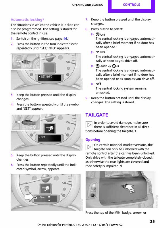
6. Press the button repeatedly until the indi-cated symbol, arrow, appears.
7. Keep the button pressed until the display changes.
8. Press button to select:
>The central locking is engaged automati-cally after a brief moment if no door has been opened.
>The central locking is engaged automati-cally as soon as you drive off.
> or The central locking is engaged automati-cally after a brief moment if no door has been opened or as soon as you drive off.
>The central locking system remains unlocked.
9. Keep the button pressed until the display changes. The setting is stored.
TailgateIn order to avoid damage, make sure there is sufficient clearance in all direc-
tions before opening the tailgate.<
OpeningOn certain national-market versions, the tailgate can only be unlocked with the
remote control after the car has been unlocked.Only drive with the tailgate completely closed, as otherwise the rear lights are covered and road safety is impaired.<
Press the top of the MINI badge, arrow, or
CONTROLS Opening and closing
26
Press and hold down the button on the remote control This will unlock the tailgate.
ClosingTo avoid injuries, ensure that the closing area of the tailgate is unobstructed.<
Recessed handles in the tailgate lining make it easier to pull the tailgate down.
Alarm system*
PrincipleThe alarm system will respond if:
> A door, the engine compartment or the tail-gate are opened
> There is movement inside the car
> The vehicle's inclination changes, for instance if an attempt is made to jack it up and steal the wheels or to raise it prior to towing away
> There is an interruption in the power supply from the battery
Depending on the national-market version of the car, the alarm system briefly indicates unau-thorised entry or tampering by means of:
> Audible alarm
> Switching on the hazard warning flashers
> Flashing the high-beam headlight
Arming and disarmingWhenever the car is locked or unlocked, the alarm system is armed or disarmed.
Even when the alarm system is armed, you can open the tailgate by means of the button on the remote control, page 23. When you sub-sequently close the luggage compartment lid, it is again locked and monitored.
Opening certain national-market versions via the door lock triggers the alarm.<
Panic mode*In the event of danger, the alarm system can be triggered.
Press the button for at least two seconds.
To switch off the alarm: Press any button.
Switching off an alarm> Unlock the car with the remote control,
page 21.
> Insert the key fully into the ignition lock.
> With convenient access* and the remote control, press the button on the door lock.
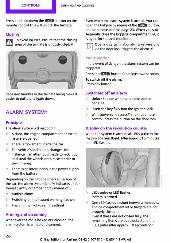
Display on the revolution counterWhen the system is armed, all LEDs pulse in the rhythm of a heartbeat. After approx. 16 minutes one LED flashes.
> LEDs pulse or LED flashes: System is armed.
> One LED flashes at short intervals: the doors, engine compartment lid or tailgate are not properly closed.Even if these are not closed fully, the remaining items are deadlocked and the LEDs pulse after approx. 10 seconds for
Opening and closing CONTROLS
27
approx. 16 minutes. Afterwards, one LED flashes. The interior movement detector is not activated.
> LEDs go out after the vehicle is unlocked: No attempt was made to tamper with the car.
> LEDs flash after unlocking until the key is inserted in the ignition, but for no longer than approx. 5 minutes: An attempt was made to tamper with the car.
Tilt alarm sensorThe vehicle's inclination is monitored. The alarm will be triggered for instance if an attempt is made to steal the vehicle's wheels or tow it away.
Interior movement detectorBefore the interior movement detector can operate correctly, the windows and glass roof must be closed*.
Avoiding false alarmsThe tilt alarm sensor and the interior movement detector can be switched off together. This pre-vents false alarms, e.g. in the following situa-tions:
> In duplex garages
> When being transported on vehicle-carrying trains, boats/ships or trailers
> If pets are to remain inside the vehicle
Switching off the tilt alarm sensor and interior movement detector> Press the button on the remote con-
trol twice in succession.
> Lock the vehicle twice with the integrated key.
LEDs flash in short succession for approx. 2 seconds. The tilt alarm sensor and interior movement detector are switched off until the next time the vehicle is unlocked and locked.
Convenient access*Convenient access enables you to access the car without having to take the remote control into your hand. It is sufficient to have the remote control on your person, for example in a jacket pocket. The vehicle automatically recognises the remote control when it is in the immediate vicin-ity or inside the car.
Operating requirements> The car or the tailgate can be locked only
when the car ascertains that the remote control on your person is not inside the car.
> About two seconds have to elapse before the car can again be unlocked and locked.
> The engine can be started only when the car ascertains that the remote control is inside the car.
> The doors and tailgate must be closed in order to operate the windows and the glass roof*.
Convenient access supports the following func-tions:
> Unlocking/locking the vehicle
> Comfort closing
> Unlock tailgate individually
> Starting the engine
Comparison to the conventional remote controlGenerally speaking, it makes no difference whether you control the functions outlined above by using convenient access or by pressing the buttons on the remote control.
Instructions for opening and closing begin on page 20.
The features specific to convenient access are described below.
A short delay when opening or closing windows or the glass roof indicates that a
test is being carried out to ascertain whether
CONTROLS Opening and closing
28
there is a remote control inside the car. If neces-sary, repeat the opening or closing operation.<
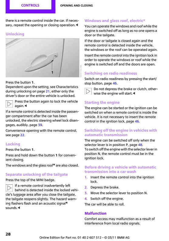
Unlocking
Press the button 1.Dependent upon the setting, see Characteristics during unlocking on page 21, either only the driver's door or the entire vehicle is unlocked.
Press the button again to lock the vehicle again.<
If a remote control is detected inside the passen-ger compartment after the car has been unlocked, the electric steering wheel lock disen-gages, audibly, page 39.
Convenience opening with the remote control, see page 22.
LockingPress the button 1.
Press and hold down the button 1 for conven-ient closing.
The windows and the glass roof* are also closed.
Separate unlocking of the tailgatePress the top of the MINI badge.
If a remote control inadvertently left behind is detected inside the locked vehi-
cle's luggage area after you close the tailgate, the tailgate reopens slightly. The hazard warn-ing flashers flash and an acoustic signal* sounds.<
Windows and glass roof, electric*You can operate the windows and roof while the engine is switched off as long as no one opens a door or the tailgate.
If the door or tailgate is closed again and the remote control is detected inside the vehicle, the windows or the roof can be operated again.
Insert the remote control into the ignition lock in order to operate the windows or roof while the engine is switched off and the doors are open.
Switching on radio readinessSwitch on radio readiness by pressing the start/stop button, page 46.
Do not depress the brake or clutch, other-wise the engine will start.<
Starting the engineThe engine can be started or the ignition can be switched on when a remote control is inside the vehicle. It is not necessary to insert the remote control in the ignition lock, page 46.
Switching off the engine in vehicles with automatic transmissionThe engine can be switched off only when the selector lever is in position P, page 48.To switch off the engine with the selector lever in position N, the remote control must be in the ignition lock.
Before driving a vehicle with automatic transmission into a car wash1. Insert the remote control into the ignition
lock.
2. Depress the brake.
3. Move the selector lever to position N.
4. Switch off the engine.
The car will be able to roll.
MalfunctionComfort access may malfunction as a result of interference from local radio signals.
Opening and closing CONTROLS
29
In this case, open or close the vehicle using the buttons on the remote control or with the inte-grated key. Insert the remote control into the ignition lock in order to start the engine.
Warning lightsWarning light comes on when you attempt to start the engine: engine starting not possible. The remote control
is not inside the vehicle or is faulty. Bring the remote control inside the vehicle or have it checked. Try inserting a different remote control in the ignition lock.
Warning light comes on while the engine is running: the remote control is no longer inside the vehicle. If the
engine is switched off, it can be restarted only within approx. 10 seconds.
Indicator light comes on: change the battery in the remote control.
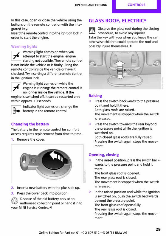
Changing the batteryThe battery in the remote control for comfort access requires replacement from time to time.
1. Remove the cover.
2. Insert a new battery with the plus side up.
3. Press the cover back into position.
Dispose of the old battery only at an authorised collecting point or hand it in to
your MINI Service Centre.<
Glass roof, electric*Observe the glass roof during the closing procedure, to avoid any injuries.
Take the key with you when you leave the car, otherwise children could operate the roof and possibly injure themselves.<
Raising> Press the switch backwards to the pressure
point and hold it there.Both glass roofs are raised.The movement is stopped when the switch is released.
> Press the switch towards the rear beyond the pressure point while the ignition is switched on.Both closed glass roofs are fully raised.Pressing the switch again stops the move-ment.
Opening, closing> In the raised position, press the switch back-
wards to the pressure point and hold it there.The front glass roof is opened.The rear glass roof is closed.The movement is stopped when the switch is released.
> In the raised position and while the ignition is switched on, push the switch backwards beyond the pressure point.The front glass roof opens fully. The rear glass roof is closed. Pressing the switch again stops the move-ment.
CONTROLS Opening and closing
30
In the same manner, the glass roof is closed by pushing the switch forwards.
The front glass roof remains in the raised posi-tion. The rear glass roof is raised. Pushing the switch again closes both roofs fully.
Convenient operation via remote control, door lock or convenient access, page 22, 24, 28.
Roller sunblindThe roller sunblind can be opened or closed sep-arately from the glass roof.
After switching off the ignitionThe roof can still be operated for approx. 1 minute while the ignition is switched off as long as no door is opened.
After a power failureAfter a power failure, it is possible that the roof will only move to the raised position. Then have the system initialised. The manufacturer of your MINI recommends having this work carried out by your MINI Service Centre.
WindowsWatch the windows during the closing action to avoid injuries.
Take remote control with you when you leave the car, otherwise children could operate the electric windows and possibly injure them-selves.<
If a window can only be closed after it has been opened and closed several times in
short succession, the system has overheated. Let the system cool down for several minutes while the ignition is switched on or the engine is running.<
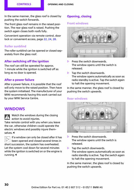
Opening, closing
Front windows
> Press the switch downwards.The window opens until the switch is released.
> Tap the switch downwards. The window opens automatically as soon as radio standby is active. Tap the switch again to halt the opening movement.
In the same manner, the glass roof is closed by pushing the switch upwards.
Rear windows
> Press the switch downwards.The window opens until the switch is released.
> Tap the switch downwards. The window opens automatically as soon as radio standby is active. Tap the switch again to halt the opening movement.
In the same manner, the glass roof is closed by pushing the switch upwards.
Opening and closing CONTROLS
31
After switching off the ignitionThe windows can still be operated for approx. 1 minute while the ignition is switched off as long as no door is opened.
Take the key with you when you leave the car, otherwise children could operate the
electric windows and possibly injure them-selves.<
Trap protectionIf the closing force of a window exceeds a specific value as it closes, the closing action is interrupted and the window reopens slightly.
Despite the trap protection function, make sure that the windows are not
obstructed as they close; if this precaution is not taken, the risk remains that thin objects, for instance, could fail to interrupt the closing movement.
Do not install any accessories in the movement range of the windows in order not to impair the trap protection function.<
Closing without the trap protection functionIn case of an external hazard, or if ice cover, for example, does not allow you to close a window normally, the window can be closed manually.
1. Push the switch upward and hold it there. The trap protection function is restricted and the window opens slightly when the closing force exceeds a certain value.
2. Within approx. 4 seconds, push the switch upward again and hold it there. The window closes without the trap protection function.
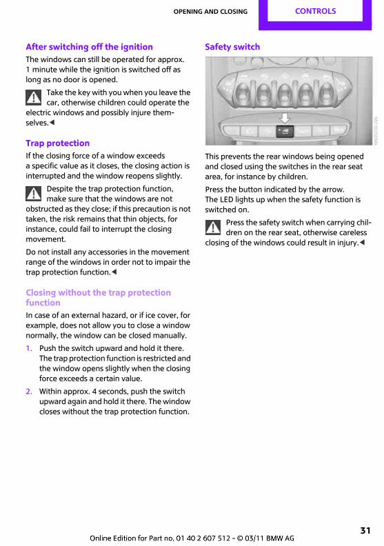
Safety switch
This prevents the rear windows being opened and closed using the switches in the rear seat area, for instance by children.
Press the button indicated by the arrow.The LED lights up when the safety function is switched on.
Press the safety switch when carrying chil-dren on the rear seat, otherwise careless
closing of the windows could result in injury.<
CONTROLS Adjusting
32
Adjusting
Safe seated positionA seated position that suitably reflects your requirements is a vital condition of relaxed driv-ing with a minimum of fatigue. In conjunction with the seat belts, the head restraints and the airbags, the seated position has a major influ-ence on your safety in the event of an accident. You should therefore observe the following notes in order to maintain the protective func-tion of the vehicle's safety systems.
For additional notes on child safety, see page 40.
AirbagsKeep your distance from the airbags. Always grip the steering wheel on the rim,
with your hands in the 3 o'clock and 9 o'clock positions, to minimise the risk of injury to the hands or arms in the event of the airbag being triggered off. No other persons, pets or objects should be held or permitted to remain between the airbag and yourself. Do not use the front airbag cover on the front passenger's side as a tray. Make sure that the front passenger adopts a correct seated posi-tion, e.g. does not rest feet or legs on the instru-ment panel; otherwise he/she could sustain leg injuries in the event of the front airbag being triggered.Make sure that passengers keep their head away from the side airbag and do not lean on the covers of the head-level airbags, otherwise they may sustain injuries in the event of the air-bags being triggered.<
Even if all these instructions are complied with, certain injuries as a result of contact with the air-bag cannot be entirely ruled out, depending on the circumstances in which an accident occurs. Occupants with sensitive hearing may be sub-ject to brief and generally temporary impaired
hearing caused by the ignition and inflation noise.
The locations of the airbags and additional notes are given on page 74.
Head restraintHead restraints adjusted to the correct height reduce the risk of injuries to the neck in the event of an accident.
Adjust the head restraint in such a way that its centre is at approximately ear
level; otherwise, there is an increased risk of injury should an accident occur.<
Head restraints, see page 34.
Seat beltAll occupants should always fasten their seat belts before you set off. The airbags are a com-plementary safety feature and not a substitute for the seat belts.
Number of seat beltsFor your safety and that of your passengers, the car is fitted with four or five* seat belts.
However, they can offer protection only when used correctly.
Adjustment for automatic retracting seat belts> Draw the buckle tongue attached to the seat
belt across the body and press it into the buckle catch until a 'click' is heard.
> Adjustment of the belt length is very impor-tant. To adjust the lap belt and check whether the buckle has locked correctly, pull upwards on the shoulder strap until the lap belt fits tightly.
> The length of the diagonal shoulder strap adjusts itself automatically to allow freedom of movement.
Adjusting CONTROLS
33
> To release the seat belt, press the button on the buckle catch unit.
Never restrain more than one person with each seat belt. Babies or small children
must not travel on the lap of another occupant.Around the pelvis, make sure that the belt sits firmly on the hips and does not press down on the stomach. The seat belt must not be worn touching the neck, pass over sharp edges or hard or fragile objects, or become trapped at any point. Pull the seat belt tight and without twisting across the pelvis and shoulder and keep it as close as possible to the body in order to avoid it slipping over the hips and injuring the stomach in the event of a frontal collision. Avoid wearing bulky clothing and regularly pull the belt in the upper-body area taut, otherwise its restraining effect could be impaired.<
Seat belts, see page 35.
Seats
Note before adjustingDo not reposition the driver's seat while the car is in motion. The seat could move
unexpectedly, leading to the driver losing con-trol of the vehicle, and possibly resulting in an accident.Do not recline the driver's or front passenger's seat back too far, otherwise there will be a risk of sliding under the seat belt in an accident, so that the belt loses its protective effect.<
Comply with the instructions on head restraint height on page 34 and on damaged seat belts on page 37.
Seat adjustment frontFailure to comply with the notes on page 33 may put your personal safety at
risk.<
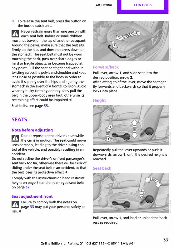
Forward/backPull lever, arrow 1, and slide seat into the desired position, arrow 2.After letting go of the lever, move the seat gen-tly forwards and backwards so that it properly locks into place.
Height
Repeatedly pull the lever upwards or push it downwards, arrow 1, until the desired height is reached.
Seat back
Pull lever, arrow 1, and load or unload the back-rest as required.
CONTROLS Adjusting
34
Lumbar support*The seat back contour can be altered to provide more support to the curved, lumbar section of the spine.
The upper edge of the pelvis and the spinal col-umn are supported, to encourage an upright but relaxed seated position.
Turn the wheel to increase or decrease the cur-vature.
Seat adjustment rearDo not adjust the rear seats whilst the vehicle is in motion, otherwise there is a
risk of injury to its occupants.Make sure that the catches on the rear seats engage properly after they have been adjusted. Otherwise the restraining effect of the seat belts could be impaired in the event of an accident.<
Forward/back
1. Pull the lever up and slide the seat to the preferred position.
2. Release the lever and move the seat forward or back slightly so that it engages.
Seat backAdjusting the backrest angle, see page 95.
Head restraints
Correctly adjusted head restraintHead restraints adjusted to the correct height reduce the risk of injuries to the neck in the event of an accident.
Adjust the head restraint to the correct height at each occupied seats, otherwise
there is an increased risk of injury in the event of an accident.<
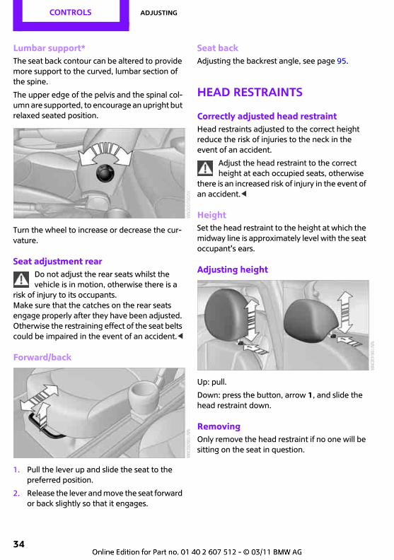
HeightSet the head restraint to the height at which the midway line is approximately level with the seat occupant's ears.
Adjusting height
Up: pull.
Down: press the button, arrow 1, and slide the head restraint down.
RemovingOnly remove the head restraint if no one will be sitting on the seat in question.
Adjusting CONTROLS
35
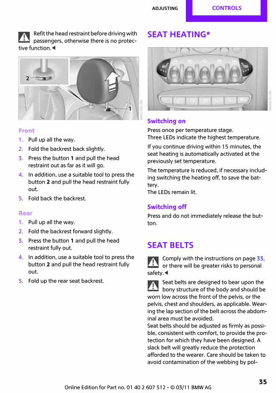
Refit the head restraint before driving with passengers, otherwise there is no protec-
tive function.<
Front1. Pull up all the way.
2. Fold the backrest back slightly.
3. Press the button 1 and pull the head restraint out as far as it will go.
4. In addition, use a suitable tool to press the button 2 and pull the head restraint fully out.
5. Fold back the backrest.
Rear1. Pull up all the way.
2. Fold the backrest forward slightly.
3. Press the button 1 and pull the head restraint fully out.
4. In addition, use a suitable tool to press the button 2 and pull the head restraint fully out.
5. Fold up the rear seat backrest.
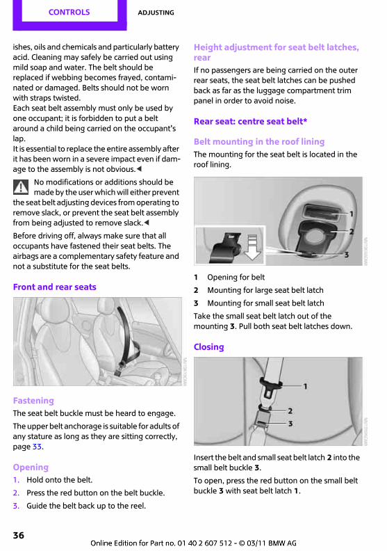
Seat heating*
Switching onPress once per temperature stage. Three LEDs indicate the highest temperature.
If you continue driving within 15 minutes, the seat heating is automatically activated at the previously set temperature.
The temperature is reduced, if necessary includ-ing switching the heating off, to save the bat-tery.The LEDs remain lit.
Switching offPress and do not immediately release the but-ton.
Seat beltsComply with the instructions on page 33, or there will be greater risks to personal
safety.<
Seat belts are designed to bear upon the bony structure of the body and should be
worn low across the front of the pelvis, or the pelvis, chest and shoulders, as applicable. Wear-ing the lap section of the belt across the abdom-inal area must be avoided.Seat belts should be adjusted as firmly as possi-ble, consistent with comfort, to provide the pro-tection for which they have been designed. A slack belt will greatly reduce the protection afforded to the wearer. Care should be taken to avoid contamination of the webbing by pol-
CONTROLS Adjusting
36
ishes, oils and chemicals and particularly battery acid. Cleaning may safely be carried out using mild soap and water. The belt should be replaced if webbing becomes frayed, contami-nated or damaged. Belts should not be worn with straps twisted.Each seat belt assembly must only be used by one occupant; it is forbidden to put a belt around a child being carried on the occupant's lap.It is essential to replace the entire assembly after it has been worn in a severe impact even if dam-age to the assembly is not obvious.<
No modifications or additions should be made by the user which will either prevent
the seat belt adjusting devices from operating to remove slack, or prevent the seat belt assembly from being adjusted to remove slack.<
Before driving off, always make sure that all occupants have fastened their seat belts. The airbags are a complementary safety feature and not a substitute for the seat belts.
Front and rear seats
FasteningThe seat belt buckle must be heard to engage.
The upper belt anchorage is suitable for adults of any stature as long as they are sitting correctly, page 33.
Opening1. Hold onto the belt.
2. Press the red button on the belt buckle.
3. Guide the belt back up to the reel.
Height adjustment for seat belt latches, rearIf no passengers are being carried on the outer rear seats, the seat belt latches can be pushed back as far as the luggage compartment trim panel in order to avoid noise.
Rear seat: centre seat belt*
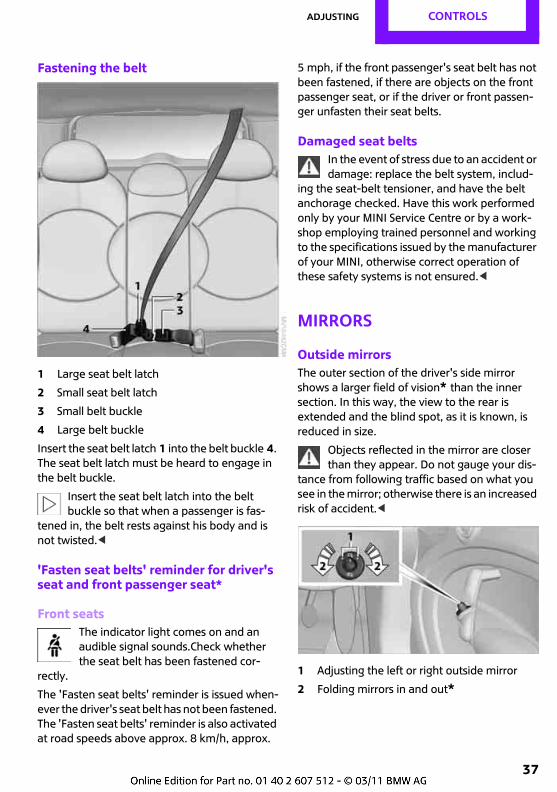
Belt mounting in the roof liningThe mounting for the seat belt is located in the roof lining.
1 Opening for belt
2 Mounting for large seat belt latch
3 Mounting for small seat belt latch
Take the small seat belt latch out of the mounting 3. Pull both seat belt latches down.
Closing
Insert the belt and small seat belt latch 2 into the small belt buckle 3.
To open, press the red button on the small belt buckle 3 with seat belt latch 1.
Adjusting CONTROLS
37
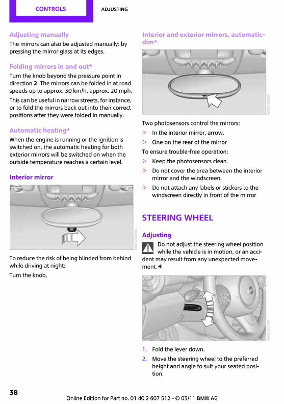
Fastening the belt
1 Large seat belt latch
2 Small seat belt latch
3 Small belt buckle
4 Large belt buckle
Insert the seat belt latch 1 into the belt buckle 4. The seat belt latch must be heard to engage in the belt buckle.
Insert the seat belt latch into the belt buckle so that when a passenger is fas-
tened in, the belt rests against his body and is not twisted.<
'Fasten seat belts' reminder for driver's seat and front passenger seat*
Front seatsThe indicator light comes on and an audible signal sounds.Check whether the seat belt has been fastened cor-
rectly.
The 'Fasten seat belts' reminder is issued when-ever the driver's seat belt has not been fastened. The 'Fasten seat belts' reminder is also activated at road speeds above approx. 8 km/h, approx.
5 mph, if the front passenger's seat belt has not been fastened, if there are objects on the front passenger seat, or if the driver or front passen-ger unfasten their seat belts.
Damaged seat beltsIn the event of stress due to an accident or damage: replace the belt system, includ-
ing the seat-belt tensioner, and have the belt anchorage checked. Have this work performed only by your MINI Service Centre or by a work-shop employing trained personnel and working to the specifications issued by the manufacturer of your MINI, otherwise correct operation of these safety systems is not ensured.<
Mirrors
Outside mirrorsThe outer section of the driver's side mirror shows a larger field of vision* than the inner section. In this way, the view to the rear is extended and the blind spot, as it is known, is reduced in size.
Objects reflected in the mirror are closer than they appear. Do not gauge your dis-
tance from following traffic based on what you see in the mirror; otherwise there is an increased risk of accident.<
1 Adjusting the left or right outside mirror
2 Folding mirrors in and out*
CONTROLS Adjusting
38
Adjusting manuallyThe mirrors can also be adjusted manually: by pressing the mirror glass at its edges.
Folding mirrors in and out*Turn the knob beyond the pressure point in direction 2. The mirrors can be folded in at road speeds up to approx. 30 km/h, approx. 20 mph.
This can be useful in narrow streets, for instance, or to fold the mirrors back out into their correct positions after they were folded in manually.
Automatic heating*When the engine is running or the ignition is switched on, the automatic heating for both exterior mirrors will be switched on when the outside temperature reaches a certain level.
Interior mirror
To reduce the risk of being blinded from behind while driving at night:
Turn the knob.
Interior and exterior mirrors, automatic-dim*
Two photosensors control the mirrors:
> In the interior mirror, arrow.
> One on the rear of the mirror
To ensure trouble-free operation:
> Keep the photosensors clean.
> Do not cover the area between the interior mirror and the windscreen.
> Do not attach any labels or stickers to the windscreen directly in front of the mirror
Steering wheel
AdjustingDo not adjust the steering wheel position while the vehicle is in motion, or an acci-
dent may result from any unexpected move-ment.<
1. Fold the lever down.
2. Move the steering wheel to the preferred height and angle to suit your seated posi-tion.
Adjusting CONTROLS
39
3. Fold the lever back up.
Do not use force to swing the lever back up; otherwise the mechanism
will be damaged.<
Electric steering lock*The steering wheel locks or unlocks automati-cally when the key is removed or inserted.
In cars with convenient access*, the steering wheel locks or unlocks automatically when the vehicle is locked or when the remote control is detected inside the vehicle.
CONTROLS Child safety
40
Child safety
Important considerations
Do not leave children unattended in the vehicle, as they could otherwise endanger
themselves and/or other persons by opening the doors, for example.<
Not for Australia/New Zealand:The front passenger seat and the outer rear seats of your MINI are suitable for the installa-tion of universal child restraint systems for all age groups, providing these have been approved for the age group in question.
Always carry children at the rearAccident research has shown that the safest place for children is on the rear seat.
Children under 12 years of age or smaller than 150 cm, approx. 5 feet, should
always travel on the rear seats and in suitable child restraint systems, otherwise there is a greater risk of injury in the event of an acci-dent.<
Your MINI Service Centre will be glad to provide advice on the selection of suitable child restraint systems.
Not for Australia/New Zealand: Exception for the front passenger seat
Seat heightOnly fit universal child restraint systems if the seat height can be adjusted. Other-
wise it will be impossible to optimise the position of the seat belt and to secure the child restraint system adequately.<
Front passenger airbagsIf you nevertheless need to fit a child restraint system on the front passenger's
seat, the front and side airbags must be deacti-vated, otherwise a child travelling on that seat will face an increased risk of injury if the airbags are triggered off, even if a child restraint system is used.<
Front passenger airbags can only be deac-tivated with the key switch for front pas-
senger airbags.<
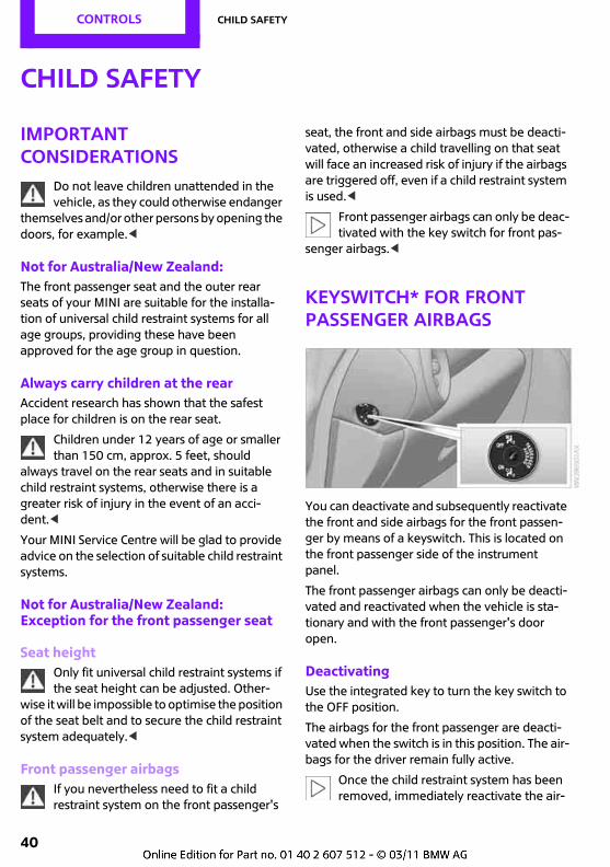
Keyswitch* for front passenger airbags
You can deactivate and subsequently reactivate the front and side airbags for the front passen-ger by means of a keyswitch. This is located on the front passenger side of the instrument panel.
The front passenger airbags can only be deacti-vated and reactivated when the vehicle is sta-tionary and with the front passenger's door open.
DeactivatingUse the integrated key to turn the key switch to the OFF position.
The airbags for the front passenger are deacti-vated when the switch is in this position. The air-bags for the driver remain fully active.
Once the child restraint system has been removed, immediately reactivate the air-
Child safety CONTROLS
41
bags for the front passenger so that they can deploy correctly in the event of an accident.<
ReactivatingUse the integrated key to turn the keyswitch to the ON position.
The front passenger airbags are reactivated and can deploy correctly if the need arises.
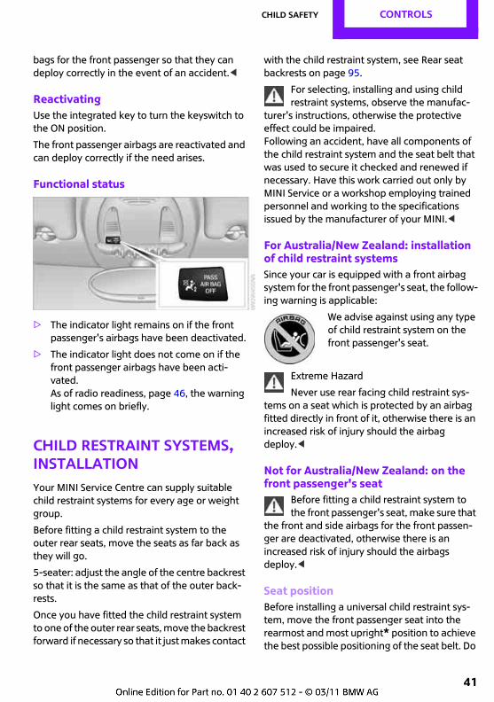
Functional status
> The indicator light remains on if the front passenger's airbags have been deactivated.
> The indicator light does not come on if the front passenger airbags have been acti-vated.As of radio readiness, page 46, the warning light comes on briefly.
Child restraint systems, installationYour MINI Service Centre can supply suitable child restraint systems for every age or weight group.
Before fitting a child restraint system to the outer rear seats, move the seats as far back as they will go.
5-seater: adjust the angle of the centre backrest so that it is the same as that of the outer back-rests.
Once you have fitted the child restraint system to one of the outer rear seats, move the backrest forward if necessary so that it just makes contact
with the child restraint system, see Rear seat backrests on page 95.
For selecting, installing and using child restraint systems, observe the manufac-
turer's instructions, otherwise the protective effect could be impaired.Following an accident, have all components of the child restraint system and the seat belt that was used to secure it checked and renewed if necessary. Have this work carried out only by MINI Service or a workshop employing trained personnel and working to the specifications issued by the manufacturer of your MINI.<
For Australia/New Zealand: installation of child restraint systemsSince your car is equipped with a front airbag system for the front passenger's seat, the follow-ing warning is applicable:
We advise against using any type of child restraint system on the front passenger's seat.
Extreme Hazard
Never use rear facing child restraint sys-tems on a seat which is protected by an airbag fitted directly in front of it, otherwise there is an increased risk of injury should the airbag deploy.<
Not for Australia/New Zealand: on the front passenger's seat
Before fitting a child restraint system to the front passenger's seat, make sure that
the front and side airbags for the front passen-ger are deactivated, otherwise there is an increased risk of injury should the airbags deploy.<
Seat positionBefore installing a universal child restraint sys-tem, move the front passenger seat into the rearmost and most upright* position to achieve the best possible positioning of the seat belt. Do
CONTROLS Child safety
42
not adjust the position of seat with the child restraint system fitted.
Not for Australia/New Zealand: child seat mountings, ISOFIX
When you are fitting and using ISOFIX child seats, comply with the operating and
safety instructions provided by the manufac-turer of the system, as otherwise the protective effect can be diminished.<
Correct ISOFIX child restraint systemsThe following ISOFIX child restraint systems can be used on the specified seats in your vehicle. The corresponding classes are indicated on the child seats themselves.
Depending on the size of the child restraint sys-tem, if necessary slide the headrest upwards and adjust the longitudinal setting of the front seat, see page 33.
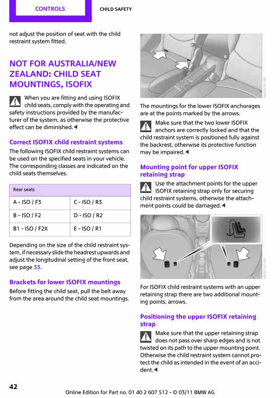
Brackets for lower ISOFIX mountingsBefore fitting the child seat, pull the belt away from the area around the child seat mountings.
The mountings for the lower ISOFIX anchorages are at the points marked by the arrows.
Make sure that the two lower ISOFIX anchors are correctly locked and that the
child restraint system is positioned fully against the backrest, otherwise its protective function may be impaired.<
Mounting point for upper ISOFIX retaining strap
Use the attachment points for the upper ISOFIX retaining strap only for securing
child restraint systems, otherwise the attach-ment points could be damaged.<
For ISOFIX child restraint systems with an upper retaining strap there are two additional mount-ing points, arrows.
Positioning the upper ISOFIX retaining strap
Make sure that the upper retaining strap does not pass over sharp edges and is not
twisted on its path to the upper mounting point. Otherwise the child restraint system cannot pro-tect the child as intended in the event of an acci-dent.<
Rear seats
A - ISO / F3 C - ISO / R3
B - ISO / F2 D - ISO / R2
B1 - ISO / F2X E - ISO / R1
Child safety CONTROLS
43
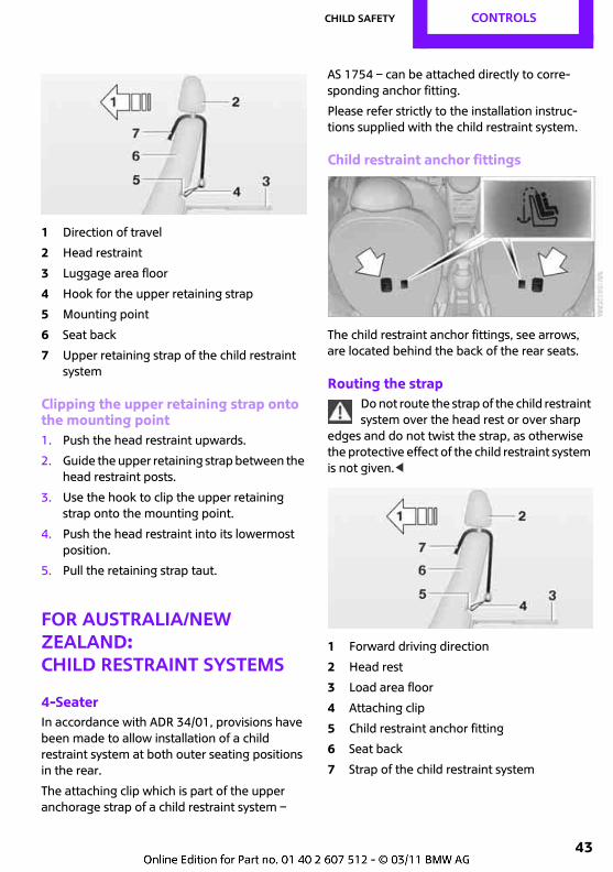
1 Direction of travel
2 Head restraint
3 Luggage area floor
4 Hook for the upper retaining strap
5 Mounting point
6 Seat back
7 Upper retaining strap of the child restraint system
Clipping the upper retaining strap onto the mounting point1. Push the head restraint upwards.
2. Guide the upper retaining strap between the head restraint posts.
3. Use the hook to clip the upper retaining strap onto the mounting point.
4. Push the head restraint into its lowermost position.
5. Pull the retaining strap taut.
For Australia/New Zealand:Child restraint systems
4-SeaterIn accordance with ADR 34/01, provisions have been made to allow installation of a child restraint system at both outer seating positions in the rear.
The attaching clip which is part of the upper anchorage strap of a child restraint system –
AS 1754 – can be attached directly to corre-sponding anchor fitting.
Please refer strictly to the installation instruc-tions supplied with the child restraint system.
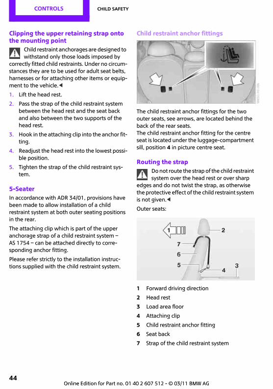
Child restraint anchor fittings
The child restraint anchor fittings, see arrows, are located behind the back of the rear seats.
Routing the strapDo not route the strap of the child restraint system over the head rest or over sharp
edges and do not twist the strap, as otherwise the protective effect of the child restraint system is not given.<
1 Forward driving direction
2 Head rest
3 Load area floor
4 Attaching clip
5 Child restraint anchor fitting
6 Seat back
7 Strap of the child restraint system
CONTROLS Child safety
44
Clipping the upper retaining strap onto the mounting point
Child restraint anchorages are designed to withstand only those loads imposed by
correctly fitted child restraints. Under no circum-stances they are to be used for adult seat belts, harnesses or for attaching other items or equip-ment to the vehicle.<
1. Lift the head rest.
2. Pass the strap of the child restraint system between the head rest and the seat back and also between the two supports of the head rest.
3. Hook in the attaching clip into the anchor fit-ting.
4. Readjust the head rest into the lowest possi-ble position.
5. Tighten the strap of the child restraint sys-tem.
5-SeaterIn accordance with ADR 34/01, provisions have been made to allow installation of a child restraint system at both outer seating positions in the rear.
The attaching clip which is part of the upper anchorage strap of a child restraint system – AS 1754 – can be attached directly to corre-sponding anchor fitting.
Please refer strictly to the installation instruc-tions supplied with the child restraint system.
Child restraint anchor fittings
The child restraint anchor fittings for the two outer seats, see arrows, are located behind the back of the rear seats.The child restraint anchor fitting for the centre seat is located under the luggage-compartment sill, position 4 in picture centre seat.
Routing the strapDo not route the strap of the child restraint system over the head rest or over sharp
edges and do not twist the strap, as otherwise the protective effect of the child restraint system is not given.<
Outer seats:
1 Forward driving direction
2 Head rest
3 Load area floor
4 Attaching clip
5 Child restraint anchor fitting
6 Seat back
7 Strap of the child restraint system
Child safety CONTROLS
45
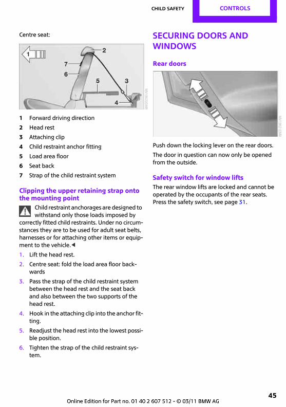
Centre seat:
1 Forward driving direction
2 Head rest
3 Attaching clip
4 Child restraint anchor fitting
5 Load area floor
6 Seat back
7 Strap of the child restraint system
Clipping the upper retaining strap onto the mounting point
Child restraint anchorages are designed to withstand only those loads imposed by
correctly fitted child restraints. Under no circum-stances they are to be used for adult seat belts, harnesses or for attaching other items or equip-ment to the vehicle.<
1. Lift the head rest.
2. Centre seat: fold the load area floor back-wards
3. Pass the strap of the child restraint system between the head rest and the seat back and also between the two supports of the head rest.
4. Hook in the attaching clip into the anchor fit-ting.
5. Readjust the head rest into the lowest possi-ble position.
6. Tighten the strap of the child restraint sys-tem.
Securing doors and windows
Rear doors
Push down the locking lever on the rear doors.
The door in question can now only be opened from the outside.
Safety switch for window liftsThe rear window lifts are locked and cannot be operated by the occupants of the rear seats. Press the safety switch, see page 31.
CONTROLS Driving
46
Driving
Ignition lock
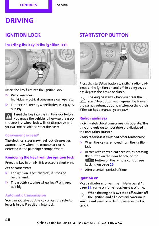
Inserting the key in the ignition lock
Insert the key fully into the ignition lock.
> Radio readinessIndividual electrical consumers can operate.
> The electric steering wheel lock* disengages audibly.
Insert the key into the ignition lock before you move the vehicle, otherwise the elec-
tric steering-wheel lock will not disengage and you will not be able to steer the car.<
Convenient access*The electrical steering-wheel lock disengages automatically when the remote control is detected in the passenger compartment.
Removing the key from the ignition lockPress the key in briefly; it is ejected a short way.
At the same time:
> The ignition is switched off, if it was on beforehand.
> The electric steering wheel lock* engages audibly.
Automatic transmissionYou cannot take out the key unless the selector lever is in the P position: interlock.
Start/stop button
Press the start/stop button to switch radio read-iness or the ignition on and off. In doing so, do not depress the brake or clutch.
The engine starts when you press the start/stop button and depress the brake if
the car has automatic transmission, or the clutch if the car has a manual gearbox.<
Radio readinessIndividual electrical consumers can operate. The time and outside temperature are displayed in the revolution counter.
Radio readiness is switched off automatically:
> When the key is removed from the ignition lock
> In cars with convenient access*, by pressing the button on the door handle or the
button on the remote control, see Locking on page 28
> After a certain period of time
Ignition onMost indicator and warning lights in panel 1, page 11, come on for various lengths of time.
When the engine is switched off, switch off the ignition and all electrical consumers
you are not using in order to preserve the bat-tery.<
Driving CONTROLS
47
Radio readiness and ignition offAll indicator lights and warning lights in the dis-plays go out.
The ignition is switched off automatically if the driver's door is opened. It is switched back on by pressing the start/stop button again.
The ignition is not switched off for example in the following situations:
> Clutch or brake depressed
> Low-beam headlights are on
> Automatic start/stop function* activated
Starting the engineNever run the engine in enclosed spaces, as inhaling the harmful exhaust gas can
lead to loss of consciousness with fatal conse-quences. The exhaust gas contains carbon mon-oxide, which is colourless and odourless, but highly toxic. Do not leave the car unattended with the engine running, as this constitutes a hazard.Before leaving the car with the engine running, place the gearbox in idle or move the selector lever to position P and fully apply the handbrake to prevent the car from moving.<
Avoid starting, stopping and restarting the engine in rapid succession or repeated
attempts to start the engine if it does not fire, otherwise unburned or only partially combusted fuel could reach the catalytic converter, which could overheat and sustain damage as a result.<
Do not warm up the engine with the car at a standstill; it is preferable to set off straight away, driving at moderate engine speeds.
Do not press the accelerator pedal while starting the engine.
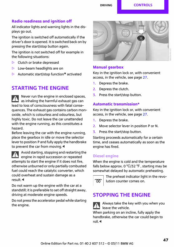
Manual gearboxKey in the ignition lock or, with convenient access, in the vehicle, see page 27.
1. Depress the brake.
2. Depress the clutch.
3. Press the start/stop button.
Automatic transmission*Key in the ignition lock or, with convenient access, in the vehicle, see page 27.
1. Depress the brake.
2. Move selector lever in position P or N.
3. Press the start/stop button.
Starting proceeds automatically for a certain time, and ceases automatically as soon as the engine has fired.
Diesel engineWhen the engine is cold and the temperature falls below approx. 06/327, starting may be somewhat delayed by automatic preheating.
The preheat indicator light in the revo-lution counter comes on.
Stopping the engineAlways take the key with you when you leave the vehicle.
When parking on an incline, fully apply the handbrake, otherwise the car could begin to roll.<
CONTROLS Driving
48
Manual gearbox1. With the car at a standstill, press the start/
stop button.
2. Engage first gear or reverse.
3. Fully apply the handbrake.
Automatic transmission*1. With the car at a standstill, move the selector
lever to position P.
2. Press the start/stop button.
3. Fully apply the handbrake.
Before entering the car washThe vehicle will be able to roll if you observe the following steps:
1. Insert master key with remote control into ignition lock, even if vehicle is equipped with convenient access.
2. Depress the brake.
3. Move the selector lever to position N.
4. Switch off the engine.
Automatic start/stop function*
The principleThe automatic start/stop function helps to save fuel and reduce emissions. For this purpose, the system switches the engine off during a stop, for example in a traffic queue or at traffic lights, the ignition remains on. As soon as you depress the clutch, the engine starts.
Automatic modeAfter every engine start, the automatic start/stop function is active and on standby.
Stopping the engine1. Move the vehicle forwards at a speed of at
least 5 km/h, approx. 3 mph, to activate the function.
2. Shift to neutral when coasting to a stop, for example at a traffic light, or when the vehi-cle is stationary.
3. Release the clutch.
With the vehicle stationary, the engine is switched off automatically and the indicator light lights up.
The air flow rate of the air conditioner/automatic air-conditioning system is reduced.
Engine is not switched offBefore the engine is switched off, the system checks whether certain conditions related to safety and comfort have been met.
In the following situations, the engine is not switched off:
> Outside temperature below approx. +36/377
> Inside of vehicle in heat-up or cool-down phase
> High outside temperature and operation of the air conditioner
> Engine not yet at operating temperature
> Battery severely depleted, see Vehicle bat-tery on page 166
> After reversing
> Driver's seat belt not fastened
Starting the engineWith the gear lever in the idle position, depress the clutch.The engine is started and the indicator
light goes out.
Engine starts automaticallyThe shut-down engine starts automatically, for example in the following cases:
Driving CONTROLS
49
> The inside of the vehicle heats up strongly and the air conditioner is switched on
> Severely depleted battery, see Vehicle bat-tery on page 166
> Low brake partial vacuum, for example due to depressing the brake a number of times in succession
> The vehicle moves off
Safety functionThe engine is not started automatically if the driver's seat belt or the engine compartment lid is opened after the
engine has been shut down automatically. The indicator light lights up. The engine can only be started using the start/stop button.
Deactivating manually
Press the button.The LED lights up.
With the system disabled, the engine can only be stopped and started using the start/stop button.
Activating manuallyPress the button again.The LED goes out.
MalfunctionThe automatic start/stop function no longer switches the engine off automat-ically. The indicator light lights up. You
can continue your journey. Have the system checked.<
HandbrakeThe handbrake is primarily intended to prevent a stationary car from rolling away; it acts on the rear wheels.
ApplyingThe lever engages automatically.
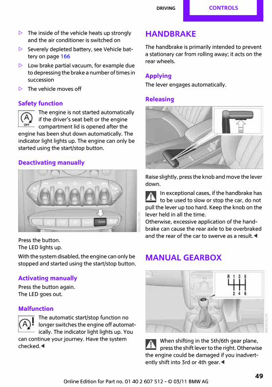
Releasing
Raise slightly, press the knob and move the lever down.
In exceptional cases, if the handbrake has to be used to slow or stop the car, do not
pull the lever up too hard. Keep the knob on the lever held in all the time.Otherwise, excessive application of the hand-brake can cause the rear axle to be overbraked and the rear of the car to swerve as a result.<
Manual gearbox
When shifting in the 5th/6th gear plane, press the shift lever to the right. Otherwise
the engine could be damaged if you inadvert-ently shift into 3rd or 4th gear.<
CONTROLS Driving
50
ReverseEngage this gear only when the vehicle is stand-ing still. When the gearshift lever is pressed to the left, a slight resistance has to be overcome.
Automatic transmission* with SteptronicIn addition to the fully automatic mode, you can perform manual gearshifts with the Steptronic, page 51.
Stopping the carBefore leaving the car with the engine running, move the selector lever to posi-
tion P and apply the handbrake to prevent the car from moving.<
Removing the keyTo remove the key from the ignition lock, move the selector lever to position P and switch off the engine: interlock. Removing the key from the ignition lock, see page 46.
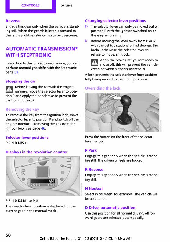
Selector lever positionsP R N D M/S + –
Displays in the revolution counter
P R N D DS M1 to M6
The selector lever position is displayed, or the current gear in the manual mode.
Changing selector lever positions> The selector lever can only be moved out of
position P with the ignition switched on or the engine running:
> Before moving the lever away from P or N with the vehicle stationary, first depress the brake, otherwise the selector lever will refuse to move: shiftlock.
Apply the brake until you are ready to move off; this will prevent the vehicle
creeping when a gear is selected.<
A lock prevents the selector lever from acciden-tally being moved to the R or P positions.
Overriding the lock
Press the button on the front of the selector lever, arrow.
P ParkEngage this gear only when the vehicle is stand-ing still. The driven wheels are locked.
R ReverseEngage this gear only when the vehicle is stand-ing still.
N NeutralSelect in car wash, for example. The vehicle will be able to roll.
D Drive, automatic positionUse this position for all normal driving. All for-ward gears are selected automatically.
Driving CONTROLS
51
Kick-downKick-down enables you to achieve maximum performance. Press the accelerator pedal beyond the increased resistance at the full-throttle position.
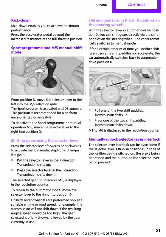
Sport programme and M/S manual-shift mode
From position D, move the selector lever to the left into the M/S selection gate:The Sport program is activated and DS appears. This position is recommended for a perform-ance-oriented driving style.
To deactivate the Sport programme or manual operation M/S, move the selector lever to the right into position D.
Shifting gears using the selector leverPress the selector lever forwards or backwards to activate manual mode. Steptronic changes the gear.
> Pull the selector lever in the + direction.Transmission shifts up.
> Press the selector lever in the – direction.Transmission shifts down.
The selected gear, for example M1, is displayed in the revolution counter.
To return to the automatic mode, move the selector lever to the right into position D.
Upshifts and downshifts are performed only at a suitable engine or road speed; for example, the transmission will not shift down if the resulting engine speed would be too high. The gear selected is briefly shown, followed by the gear currently in use.
Shifting gears using the shift paddles on the steering wheel*With the selector lever in automatic-drive posi-tion D, you can shift gears directly via the shift paddles on the steering wheel. The car automat-ically switches to manual mode.
If for a certain amount of time you neither shift gears using the shift paddles nor accelerate, the car automatically switches back to automatic-drive position D.
> Pull one of the two shift paddles.Transmission shifts up.
> Press one of the two shift paddles.Transmission shifts down.
M1 to M6 is displayed in the revolution counter.
Manually unlock selector lever interlockThe selector lever interlock can be overridden if the selector lever is stuck in position P, in spite of the ignition being switched on, the brake being depressed and the button on the selector lever being pressed:
CONTROLS Driving
52
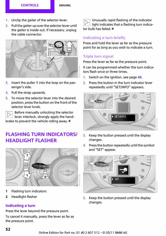
1. Unclip the gaiter of the selector lever.
2. Pull the gaiter up over the selector lever until the gaiter is inside out. If necessary, unplug the cable connector.
3. Insert the puller 1 into the loop on the pas-senger's side.
4. Pull the strap upwards.
5. To move the selector lever into the desired position, press the button on the front of the selector lever knob.
Before manually unlocking the selector lever interlock, strongly apply the hand-
brake to prevent the vehicle rolling away.<
Flashing turn indicators/headlight flasher
1 Flashing turn indicators
2 Headlight flasher
Indicating a turnPress the lever beyond the pressure point.
To cancel it manually, press the lever as far as the pressure point.
Unusually rapid flashing of the indicator light indicates that a flashing turn indica-
tor bulb has failed.<
Indicating a turn brieflyPress and hold the lever as far as the pressure point for as long as you wish to indicate a turn.
Triple turn signalPress the lever as far as the pressure point.
It can be programmed whether the turn indica-tors flash once or three times.
1. Switch on the ignition, see page 46.
2. Press the button in the turn indicator lever repeatedly until "SET/INFO" appears.
3. Keep the button pressed until the display changes.
4. Press the button repeatedly until the symbol and "SET" appear.
5. Keep the button pressed until the display changes.
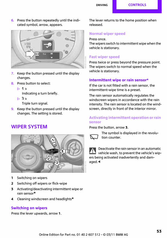
Driving CONTROLS
53
6. Press the button repeatedly until the indi-cated symbol, arrow, appears.
7. Keep the button pressed until the display changes.
8. Press button to select:
>Indicating a turn briefly.
>Triple turn signal.
9. Keep the button pressed until the display changes. The setting is stored.
Wiper system
1 Switching on wipers
2 Switching off wipers or flick-wipe
3 Activating/deactivating intermittent wipe or rain sensor*
4 Cleaning windscreen and headlights*
Switching on wipersPress the lever upwards, arrow 1.
The lever returns to the home position when released.
Normal wiper speedPress once.The wipers switch to intermittent wipe when the vehicle is stationary.
Fast wiper speedPress twice or press beyond the pressure point.The wipers switch to normal speed when the vehicle is stationary.
Intermittent wipe or rain sensor*If the car is not fitted with a rain sensor, the intermittent-wipe time is a preset.
The rain sensor automatically regulates the windscreen wipers in accordance with the rain intensity. The rain sensor is located on the wind-screen, directly in front of the interior mirror.
Activating intermittent operation or rain sensorPress the button, arrow 3.
The symbol is displayed in the revolu-tion counter.
Deactivate the rain sensor in an automatic vehicle wash, to prevent the vehicle's wip-
ers being activated inadvertently and dam-aged.<
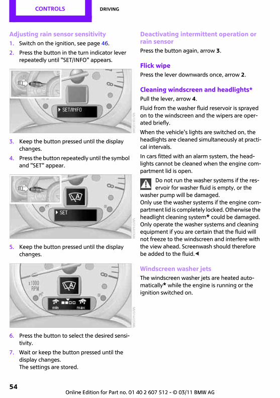
CONTROLS Driving
54
Adjusting rain sensor sensitivity1. Switch on the ignition, see page 46.
2. Press the button in the turn indicator lever repeatedly until "SET/INFO" appears.
3. Keep the button pressed until the display changes.
4. Press the button repeatedly until the symbol and "SET" appear.
5. Keep the button pressed until the display changes.
6. Press the button to select the desired sensi-tivity.
7. Wait or keep the button pressed until the display changes.The settings are stored.
Deactivating intermittent operation or rain sensorPress the button again, arrow 3.
Flick wipePress the lever downwards once, arrow 2.
Cleaning windscreen and headlights*Pull the lever, arrow 4.
Fluid from the washer fluid reservoir is sprayed on to the windscreen and the wipers are oper-ated briefly.
When the vehicle's lights are switched on, the headlights are cleaned simultaneously at practi-cal intervals.
In cars fitted with an alarm system, the head-lights cannot be cleaned when the engine com-partment lid is open.
Do not run the washer systems if the res-ervoir for washer fluid is empty, or the
washer pump will be damaged. Only use the washer systems if the engine com-partment lid is completely locked. Otherwise the headlight cleaning system* could be damaged. Only operate the washer systems and cleaning equipment if you are certain that the fluid will not freeze to the windscreen and interfere with the view ahead. Screenwash should therefore be added to the fluid.<
Windscreen washer jetsThe windscreen washer jets are heated auto-matically* while the engine is running or the ignition switched on.
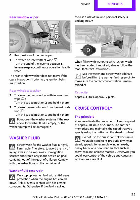
Driving CONTROLS
55
Rear window wiper
0 Rest position of the rear wiper
1 To switch on intermittent wipe :Turn the end of the lever to position 1.In reverse gear, continuous operation is acti-vated.
The rear window washer does not move if the cap is in position 1 prior to the ignition being switched on.
Rear window washer2 To clean the rear window with intermittent
wipe :Turn the cap to position 2 and hold it there.
3 To clean the rear window from the rest posi-tion :Turn the cap to position 3 and hold it there.
Do not run the washer systems if the res-ervoir for washer fluid is empty, or the
washer pump will be damaged.<
Washer fluidScreenwash for the washer fluid is highly flammable. Therefore, to avoid the risk of
injury, it has to be kept away from ignition sources and stored only in the sealed original container out of the reach of children. Comply with the instructions on the container.<
Washer fluid reservoirOnly top up washer fluid with anti-freeze protection when the engine has cooled
down. This prevents contact with hot engine components. Otherwise, if the fluid is spilled,
there is a risk of fire and personal safety is endangered.<
When filling with water, to which screenwash has been added if required, always follow the manufacturer's instructions.
Mix the water and screenwash additive before filling the washer fluid reservoir, to
make sure the correct concentration is main-tained.<
CapacityApprox. 4 litres, approx. 7 pints.
Cruise control*
The principleYou can activate the cruise control from a speed of approx. 30 km/h or 20 mph. The car then memorises and maintains the speed that you specify using the button on the steering wheel.
Do not use the cruise control when unfa-vourable conditions preclude driving at
steady speeds, for example winding roads, heavy traffic or a poor road surface such as snow, rain, ice, or loose material. Otherwise you could lose control of the vehicle and cause an accident as a result.<
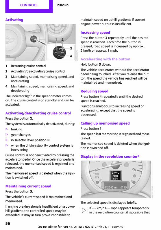
CONTROLS Driving
56
Activating
1 Resuming cruise control
2 Activating/deactivating cruise control
3 Maintaining speed, memorising speed, and accelerating
4 Maintaining speed, memorising speed, and decelerating
The indicator light in the speedometer comes on. The cruise control is on standby and can be activated.
Activating/deactivating cruise controlPress the button 2.
The system is automatically deactivated, during:
> braking
> gear changes
> in selector lever position N
> when the driving stability control system is intervening
Cruise control is not deactivated by pressing the accelerator pedal. Once the accelerator pedal is released, the memorised speed is regained and maintained.
The memorised speed is deleted when the igni-tion is switched off.
Maintaining current speedPress the button 3.
The vehicle's current speed is maintained and memorised.
If engine braking alone is insufficient on a down-hill gradient, the controlled speed may be exceeded. It may in turn prove impossible to
maintain speed on uphill gradients if current engine power output is insufficient.
Increasing speedPress the button 3 repeatedly until the desired speed is reached. Each time the button is pressed, road speed is increased by approx. 2 km/h or approx. 1 mph.
Accelerating with the buttonHold button 3 down.
The vehicle accelerates without the accelerator pedal being touched. After you release the but-ton, the speed the vehicle has reached will be maintained and memorised.
Reducing speedPress button 4 repeatedly until the desired speed is reached.
Functions analogous to increasing speed or accelerating, except that the speed is decreased.
Calling up memorised speedPress button 1.
The speed last memorised is regained and main-tained.
The memorised speed is deleted when the igni-tion is switched off.
Display in the revolution counter*
The selected speed is displayed briefly.
If --- km/h (--- mph) appears temporarily in the revolution counter, it is possible that
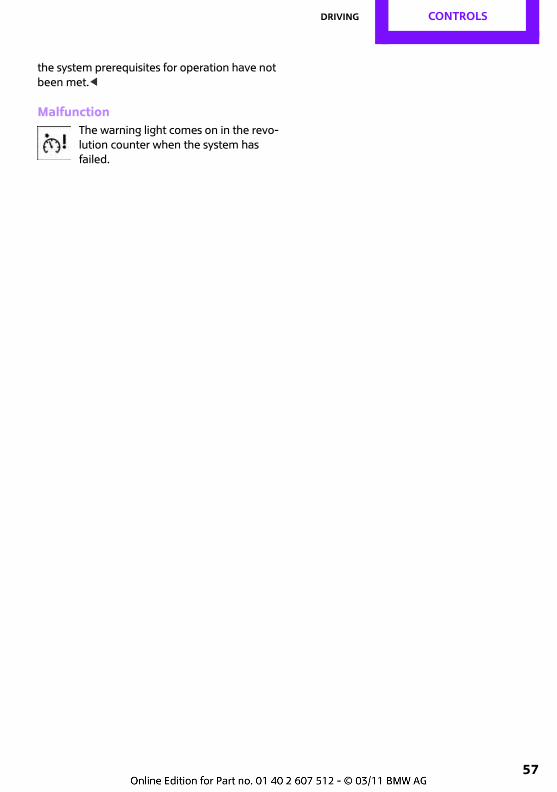
Driving CONTROLS
57
the system prerequisites for operation have not been met.<
MalfunctionThe warning light comes on in the revo-lution counter when the system has failed.
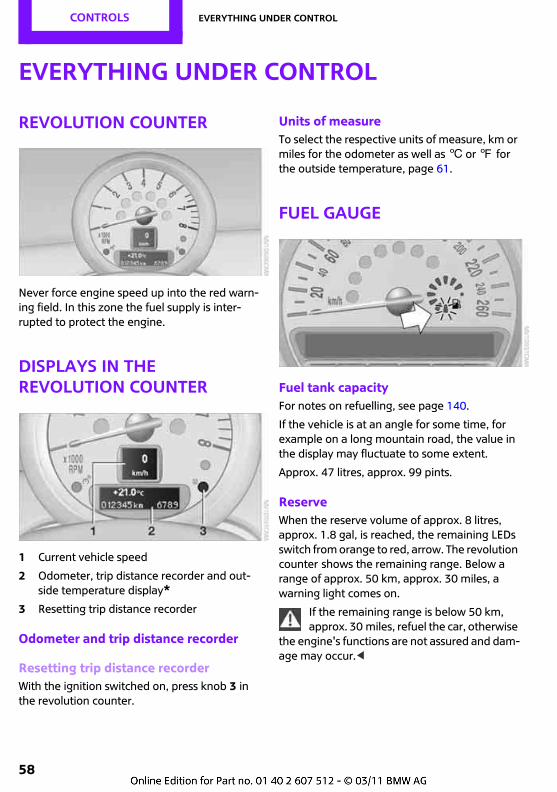
CONTROLS Everything under control
58
Everything under control
Revolution counter
Never force engine speed up into the red warn-ing field. In this zone the fuel supply is inter-rupted to protect the engine.
Displays in the revolution counter
1 Current vehicle speed
2 Odometer, trip distance recorder and out-side temperature display*
3 Resetting trip distance recorder
Odometer and trip distance recorder
Resetting trip distance recorderWith the ignition switched on, press knob 3 in the revolution counter.
Units of measureTo select the respective units of measure, km or miles for the odometer as well as 6 or 7 for the outside temperature, page 61.
Fuel gauge
Fuel tank capacityFor notes on refuelling, see page 140.
If the vehicle is at an angle for some time, for example on a long mountain road, the value in the display may fluctuate to some extent.
Approx. 47 litres, approx. 99 pints.
ReserveWhen the reserve volume of approx. 8 litres, approx. 1.8 gal, is reached, the remaining LEDs switch from orange to red, arrow. The revolution counter shows the remaining range. Below a range of approx. 50 km, approx. 30 miles, a warning light comes on.
If the remaining range is below 50 km, approx. 30 miles, refuel the car, otherwise
the engine's functions are not assured and dam-age may occur.<
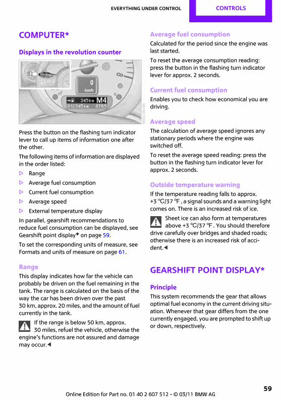
Everything under control CONTROLS
59
Computer*
Displays in the revolution counter
Press the button on the flashing turn indicator lever to call up items of information one after the other.
The following items of information are displayed in the order listed:
> Range
> Average fuel consumption
> Current fuel consumption
> Average speed
> External temperature display
In parallel, gearshift recommendations to reduce fuel consumption can be displayed, see Gearshift point display* on page 59.
To set the corresponding units of measure, see Formats and units of measure on page 61.
RangeThis display indicates how far the vehicle can probably be driven on the fuel remaining in the tank. The range is calculated on the basis of the way the car has been driven over the past 30 km, approx. 20 miles, and the amount of fuel currently in the tank.
If the range is below 50 km, approx. 30 miles, refuel the vehicle, otherwise the
engine's functions are not assured and damage may occur.<
Average fuel consumptionCalculated for the period since the engine was last started.
To reset the average consumption reading: press the button in the flashing turn indicator lever for approx. 2 seconds.
Current fuel consumptionEnables you to check how economical you are driving.
Average speedThe calculation of average speed ignores any stationary periods where the engine was switched off.
To reset the average speed reading: press the button in the flashing turn indicator lever for approx. 2 seconds.
Outside temperature warningIf the temperature reading falls to approx. +36/377, a signal sounds and a warning light comes on. There is an increased risk of ice.
Sheet ice can also form at temperatures above +36/377. You should therefore
drive carefully over bridges and shaded roads; otherwise there is an increased risk of acci-dent.<
Gearshift point display*
PrincipleThis system recommends the gear that allows optimal fuel economy in the current driving situ-ation. Whenever that gear differs from the one currently engaged, you are prompted to shift up or down, respectively.
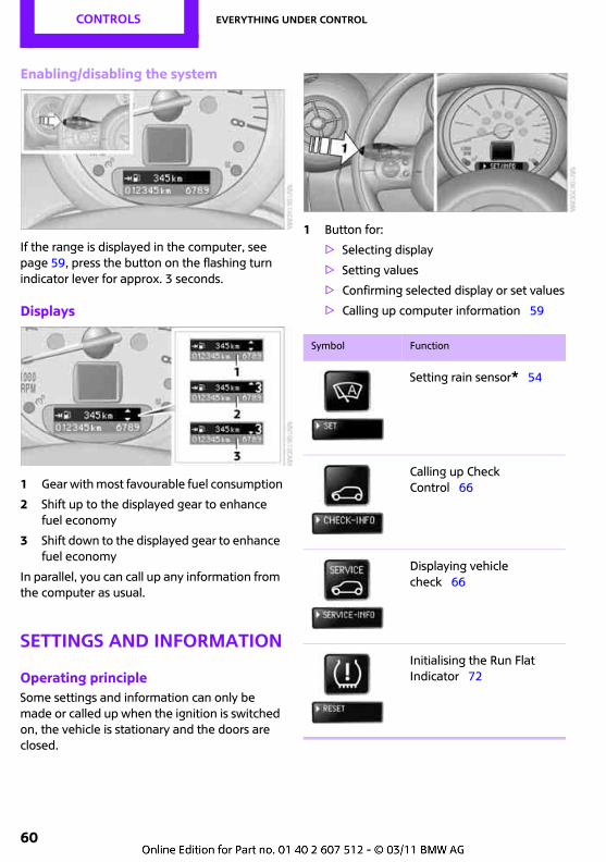
CONTROLS Everything under control
60
Enabling/disabling the system
If the range is displayed in the computer, see page 59, press the button on the flashing turn indicator lever for approx. 3 seconds.
Displays
1 Gear with most favourable fuel consumption
2 Shift up to the displayed gear to enhance fuel economy
3 Shift down to the displayed gear to enhance fuel economy
In parallel, you can call up any information from the computer as usual.
Settings and information
Operating principleSome settings and information can only be made or called up when the ignition is switched on, the vehicle is stationary and the doors are closed.
1 Button for:
> Selecting display
> Setting values
> Confirming selected display or set values
> Calling up computer information 59
Symbol Function
Setting rain sensor* 54
Calling up Check Control 66
Displaying vehicle check 66
Initialising the Run Flat Indicator 72
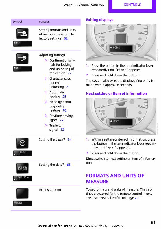
Everything under control CONTROLS
61
Exiting displays
1. Press the button in the turn indicator lever repeatedly until "HOME" appears.
2. Press and hold down the button.
The system also exits the displays if no entry is made within approx. 8 seconds.
Next setting or item of information
1. Within a setting or item of information, press the button in the turn indicator lever repeat-edly until "NEXT" appears.
2. Press and hold down the button.
Direct switch to next setting or item of informa-tion.
Formats and units of measureTo set formats and units of measure. The set-tings are stored for the remote control in use, see also Personal Profile on page 20.
Setting formats and units of measure, resetting to factory settings 62
Adjusting settings
> Confirmation sig-nals for locking and unlocking of the vehicle 22
> Characteristics during unlocking 21
> Automatic locking 25
> Headlight cour-tesy delay feature 76
> Daytime driving lights 77
> Triple turn signal 52
Setting the clock* 64
Setting the date* 65
Exiting a menu
Symbol Function
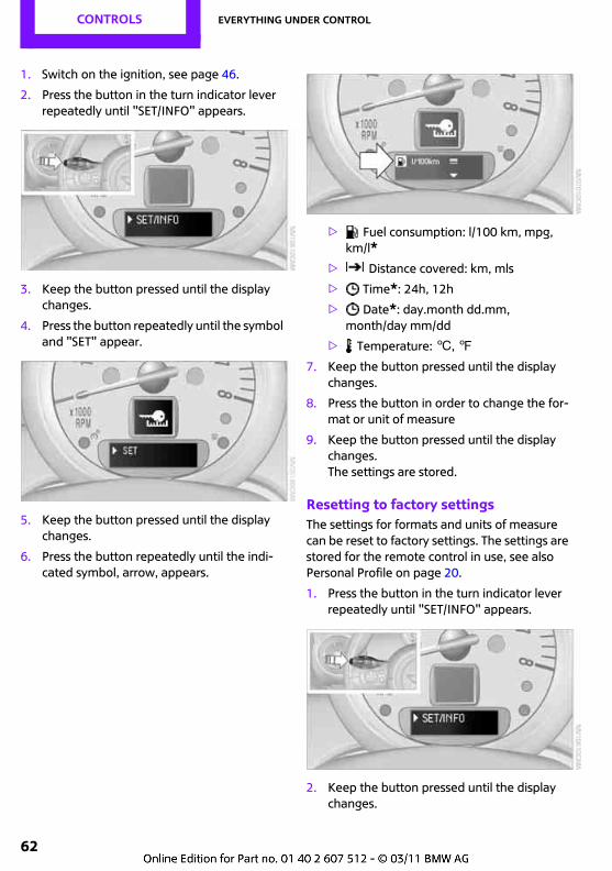
CONTROLS Everything under control
62
1. Switch on the ignition, see page 46.
2. Press the button in the turn indicator lever repeatedly until "SET/INFO" appears.
3. Keep the button pressed until the display changes.
4. Press the button repeatedly until the symbol and "SET" appear.
5. Keep the button pressed until the display changes.
6. Press the button repeatedly until the indi-cated symbol, arrow, appears.
> Fuel consumption: l/100 km, mpg, km/l*
> Distance covered: km, mls
> Time*: 24h, 12h
> Date*: day.month dd.mm, month/day mm/dd
> Temperature: 6, 7
7. Keep the button pressed until the display changes.
8. Press the button in order to change the for-mat or unit of measure
9. Keep the button pressed until the display changes.The settings are stored.
Resetting to factory settingsThe settings for formats and units of measure can be reset to factory settings. The settings are stored for the remote control in use, see also Personal Profile on page 20.
1. Press the button in the turn indicator lever repeatedly until "SET/INFO" appears.
2. Keep the button pressed until the display changes.
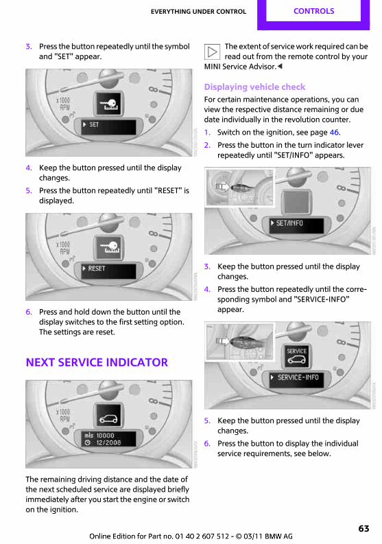
Everything under control CONTROLS
63
3. Press the button repeatedly until the symbol and "SET" appear.
4. Keep the button pressed until the display changes.
5. Press the button repeatedly until "RESET" is displayed.
6. Press and hold down the button until the display switches to the first setting option. The settings are reset.
Next Service indicator
The remaining driving distance and the date of the next scheduled service are displayed briefly immediately after you start the engine or switch on the ignition.
The extent of service work required can be read out from the remote control by your
MINI Service Advisor.<
Displaying vehicle checkFor certain maintenance operations, you can view the respective distance remaining or due date individually in the revolution counter.
1. Switch on the ignition, see page 46.
2. Press the button in the turn indicator lever repeatedly until "SET/INFO" appears.
3. Keep the button pressed until the display changes.
4. Press the button repeatedly until the corre-sponding symbol and "SERVICE-INFO" appear.
5. Keep the button pressed until the display changes.
6. Press the button to display the individual service requirements, see below.
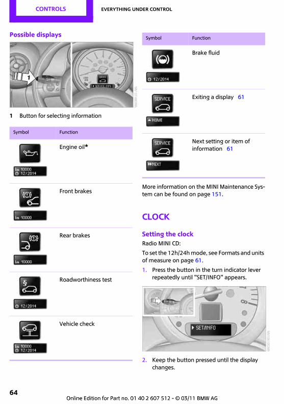
CONTROLS Everything under control
64
Possible displays
1 Button for selecting information
More information on the MINI Maintenance Sys-tem can be found on page 151.
Clock
Setting the clockRadio MINI CD:
To set the 12h/24h mode, see Formats and units of measure on page 61.
1. Press the button in the turn indicator lever repeatedly until "SET/INFO" appears.
2. Keep the button pressed until the display changes.
Symbol Function
Engine oil*
Front brakes
Rear brakes
Roadworthiness test
Vehicle check
Brake fluid
Exiting a display 61
Next setting or item of information 61
Symbol Function
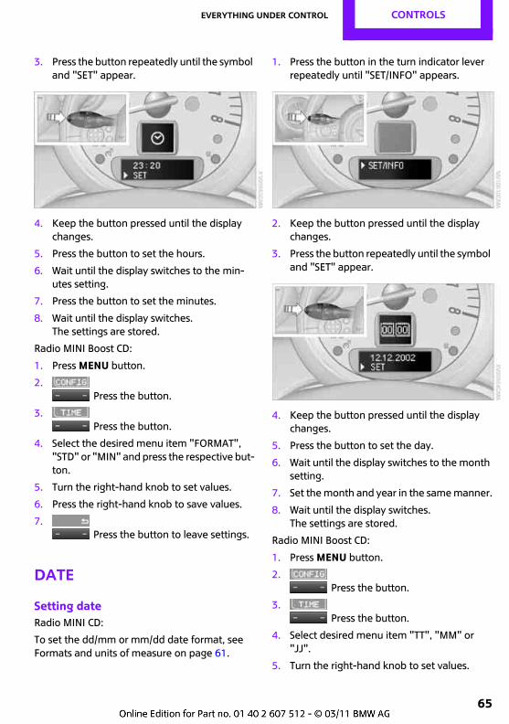
Everything under control CONTROLS
65
3. Press the button repeatedly until the symbol and "SET" appear.
4. Keep the button pressed until the display changes.
5. Press the button to set the hours.
6. Wait until the display switches to the min-utes setting.
7. Press the button to set the minutes.
8. Wait until the display switches.The settings are stored.
Radio MINI Boost CD:
1. Press MENU button.
2.Press the button.
3.Press the button.
4. Select the desired menu item "FORMAT", "STD" or "MIN" and press the respective but-ton.
5. Turn the right-hand knob to set values.
6. Press the right-hand knob to save values.
7. Press the button to leave settings.
Date
Setting dateRadio MINI CD:
To set the dd/mm or mm/dd date format, see Formats and units of measure on page 61.
1. Press the button in the turn indicator lever repeatedly until "SET/INFO" appears.
2. Keep the button pressed until the display changes.
3. Press the button repeatedly until the symbol and "SET" appear.
4. Keep the button pressed until the display changes.
5. Press the button to set the day.
6. Wait until the display switches to the month setting.
7. Set the month and year in the same manner.
8. Wait until the display switches.The settings are stored.
Radio MINI Boost CD:
1. Press MENU button.
2.Press the button.
3.Press the button.
4. Select desired menu item "TT", "MM" or "JJ".
5. Turn the right-hand knob to set values.
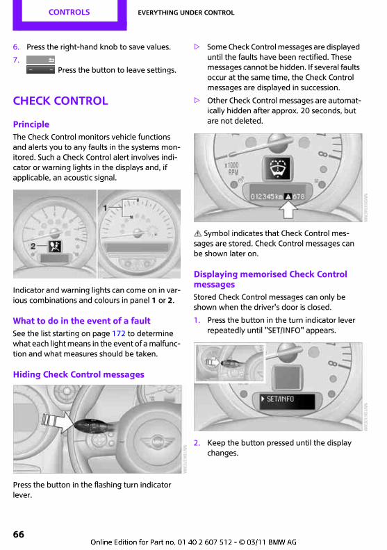
CONTROLS Everything under control
66
6. Press the right-hand knob to save values.
7. Press the button to leave settings.
Check Control
PrincipleThe Check Control monitors vehicle functions and alerts you to any faults in the systems mon-itored. Such a Check Control alert involves indi-cator or warning lights in the displays and, if applicable, an acoustic signal.
Indicator and warning lights can come on in var-ious combinations and colours in panel 1 or 2.
What to do in the event of a faultSee the list starting on page 172 to determine what each light means in the event of a malfunc-tion and what measures should be taken.
Hiding Check Control messages
Press the button in the flashing turn indicator lever.
> Some Check Control messages are displayed until the faults have been rectified. These messages cannot be hidden. If several faults occur at the same time, the Check Control messages are displayed in succession.
> Other Check Control messages are automat-ically hidden after approx. 20 seconds, but are not deleted.
Symbol indicates that Check Control mes-sages are stored. Check Control messages can be shown later on.
Displaying memorised Check Control messagesStored Check Control messages can only be shown when the driver's door is closed.
1. Press the button in the turn indicator lever repeatedly until "SET/INFO" appears.
2. Keep the button pressed until the display changes.
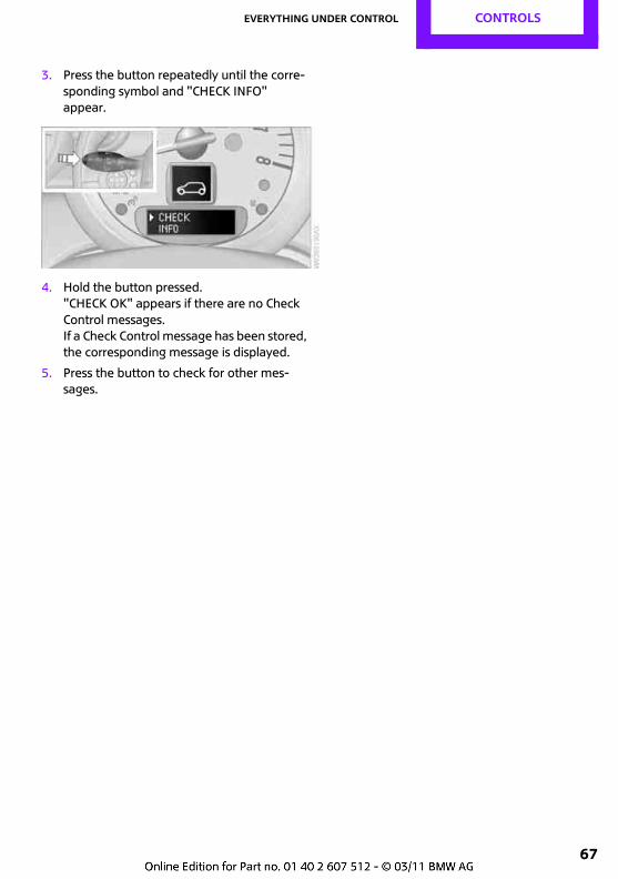
Everything under control CONTROLS
67
3. Press the button repeatedly until the corre-sponding symbol and "CHECK INFO" appear.
4. Hold the button pressed."CHECK OK" appears if there are no Check Control messages.If a Check Control message has been stored, the corresponding message is displayed.
5. Press the button to check for other mes-sages.
CONTROLS Technical features for driving comfort and safety
68
Technical features for driving comfort and safety
Park Distance Control PDC*
PrinciplePDC assists you with manoeuvring into a parking space. Acoustic signals warn you of the presence of an object behind the car. Four ultrasonic sen-sors in the rear bumper perform the measure-ments.
An acoustic signal sounds once an object is approx. 60 cm, approx. 24 in, from the
rear corner sensors, or approx. 1.50 m, approx. 5 ft, from the rear centre sensors. PDC is a park-ing aid which is capable of registering objects approached at low speed, as is usually the case when the car is being parked. Avoid approach-ing an object rapidly, otherwise the system may be unable to alert you in sufficient time due to the physical principles involved.<
If the car is towing a trailer, the rear sensors will be unable to supply meaningful signals. They therefore do not light up.
Automatic modeWith the engine running or the ignition switched on, the system is activated after approx. one second when reverse gear or selector lever position R is engaged. Wait for a brief moment before driving off.
Audible warning signalsThe closer the car approaches the object, the more rapid the sequence of signals. When the distance to a detected object is less than approx. 30 cm, approx. 12 in, the signal becomes con-tinuous.
If the distance remains constant, e.g. if you are driving parallel to a wall, the signal is interrupted after approx. 3 seconds.
AdjustingThe volume of the signal tones can be adjusted, see Radio MINI CD, page 108 or Radio MINI Boost CD, page 114.
MalfunctionIndicator light comes on. PDC has failed. Have the system checked.
As a precautionary measure, keep the sensors clean and free from ice, so that they always operate reliably. When using a high-pressure cleaner, do not spray the sensors for extended periods of time and only from a dis-tance of at least 10 cm, approx. 4 in.
System limitationsPDC is no substitute for your personal assessment of obstructions. The sensors
have certain dead areas in which objects cannot be detected. In addition, the identification of objects may not be possible if the physical limits of the ultrasonic measuring principle are exceeded, for instance with trailer noses and hitches, and thin or wedge-shaped objects. Low objects already indicated, such as kerbs, may enter the sensors' dead areas before or after a continuous audible signal is given. Higher, pro-truding objects such as ledges may not be detectable. For this reason, drive prudently, as otherwise there is a risk of personal injury or damage to property. Loud sound sources out-side or inside the vehicle can drown out the PDC signal.<
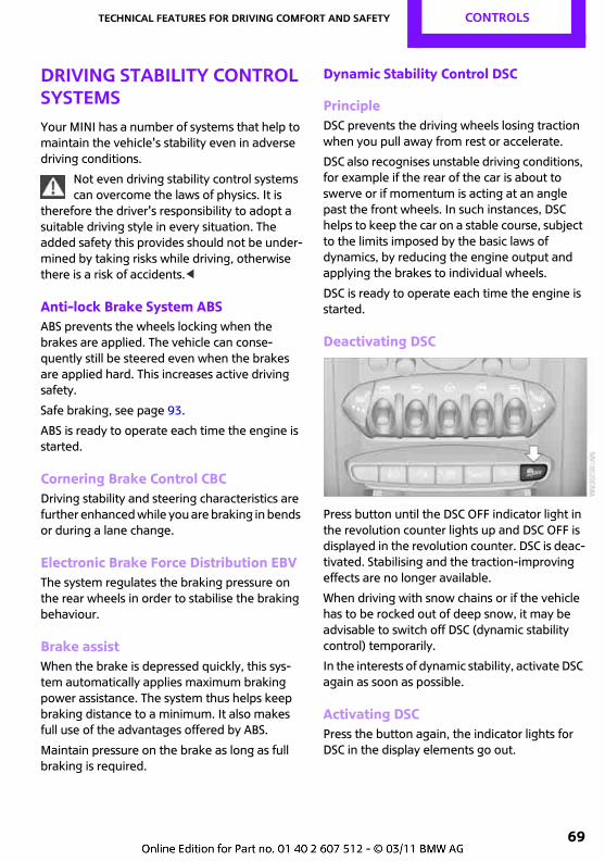
Technical features for driving comfort and safety CONTROLS
69
Driving stability control systemsYour MINI has a number of systems that help to maintain the vehicle's stability even in adverse driving conditions.
Not even driving stability control systems can overcome the laws of physics. It is
therefore the driver's responsibility to adopt a suitable driving style in every situation. The added safety this provides should not be under-mined by taking risks while driving, otherwise there is a risk of accidents.<
Anti-lock Brake System ABSABS prevents the wheels locking when the brakes are applied. The vehicle can conse-quently still be steered even when the brakes are applied hard. This increases active driving safety.
Safe braking, see page 93.
ABS is ready to operate each time the engine is started.
Cornering Brake Control CBCDriving stability and steering characteristics are further enhanced while you are braking in bends or during a lane change.
Electronic Brake Force Distribution EBVThe system regulates the braking pressure on the rear wheels in order to stabilise the braking behaviour.
Brake assistWhen the brake is depressed quickly, this sys-tem automatically applies maximum braking power assistance. The system thus helps keep braking distance to a minimum. It also makes full use of the advantages offered by ABS.
Maintain pressure on the brake as long as full braking is required.
Dynamic Stability Control DSC
PrincipleDSC prevents the driving wheels losing traction when you pull away from rest or accelerate.
DSC also recognises unstable driving conditions, for example if the rear of the car is about to swerve or if momentum is acting at an angle past the front wheels. In such instances, DSC helps to keep the car on a stable course, subject to the limits imposed by the basic laws of dynamics, by reducing the engine output and applying the brakes to individual wheels.
DSC is ready to operate each time the engine is started.
Deactivating DSC
Press button until the DSC OFF indicator light in the revolution counter lights up and DSC OFF is displayed in the revolution counter. DSC is deac-tivated. Stabilising and the traction-improving effects are no longer available.
When driving with snow chains or if the vehicle has to be rocked out of deep snow, it may be advisable to switch off DSC (dynamic stability control) temporarily.
In the interests of dynamic stability, activate DSC again as soon as possible.
Activating DSCPress the button again, the indicator lights for DSC in the display elements go out.
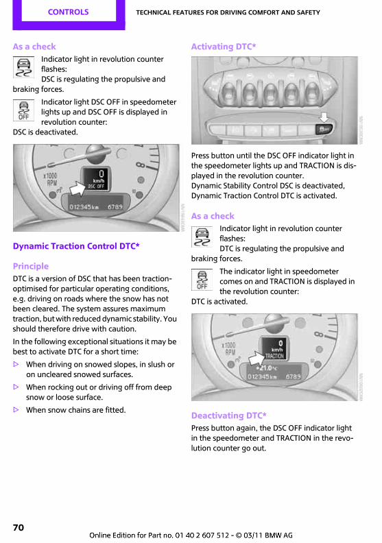
CONTROLS Technical features for driving comfort and safety
70
As a checkIndicator light in revolution counter flashes: DSC is regulating the propulsive and
braking forces.
Indicator light DSC OFF in speedometer lights up and DSC OFF is displayed in revolution counter:
DSC is deactivated.
Dynamic Traction Control DTC*
PrincipleDTC is a version of DSC that has been traction-optimised for particular operating conditions, e.g. driving on roads where the snow has not been cleared. The system assures maximum traction, but with reduced dynamic stability. You should therefore drive with caution.
In the following exceptional situations it may be best to activate DTC for a short time:
> When driving on snowed slopes, in slush or on uncleared snowed surfaces.
> When rocking out or driving off from deep snow or loose surface.
> When snow chains are fitted.
Activating DTC*
Press button until the DSC OFF indicator light in the speedometer lights up and TRACTION is dis-played in the revolution counter.Dynamic Stability Control DSC is deactivated, Dynamic Traction Control DTC is activated.
As a checkIndicator light in revolution counter flashes: DTC is regulating the propulsive and
braking forces.
The indicator light in speedometer comes on and TRACTION is displayed in the revolution counter:
DTC is activated.
Deactivating DTC*Press button again, the DSC OFF indicator light in the speedometer and TRACTION in the revo-lution counter go out.
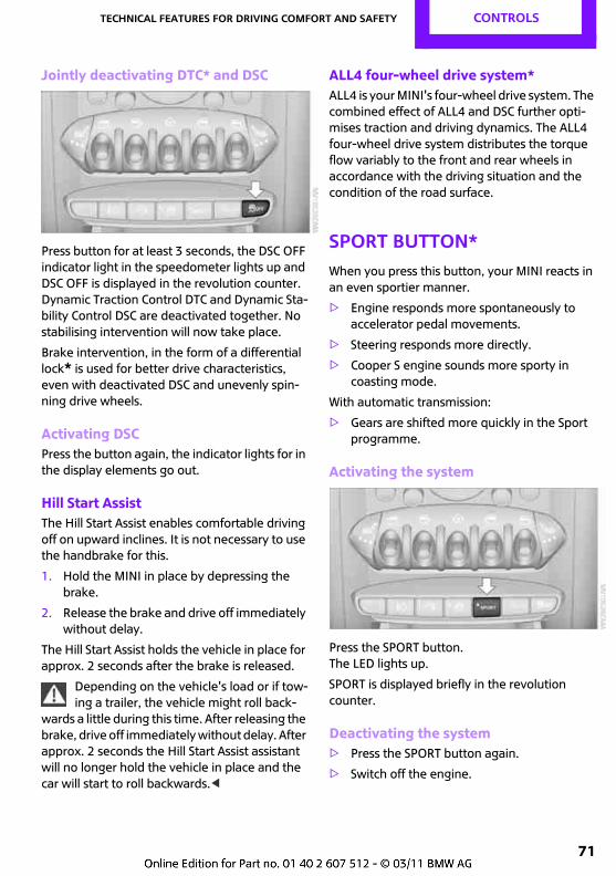
Technical features for driving comfort and safety CONTROLS
71
Jointly deactivating DTC* and DSC
Press button for at least 3 seconds, the DSC OFF indicator light in the speedometer lights up and DSC OFF is displayed in the revolution counter.Dynamic Traction Control DTC and Dynamic Sta-bility Control DSC are deactivated together. No stabilising intervention will now take place.
Brake intervention, in the form of a differential lock* is used for better drive characteristics, even with deactivated DSC and unevenly spin-ning drive wheels.
Activating DSCPress the button again, the indicator lights for in the display elements go out.
Hill Start AssistThe Hill Start Assist enables comfortable driving off on upward inclines. It is not necessary to use the handbrake for this.
1. Hold the MINI in place by depressing the brake.
2. Release the brake and drive off immediately without delay.
The Hill Start Assist holds the vehicle in place for approx. 2 seconds after the brake is released.
Depending on the vehicle's load or if tow-ing a trailer, the vehicle might roll back-
wards a little during this time. After releasing the brake, drive off immediately without delay. After approx. 2 seconds the Hill Start Assist assistant will no longer hold the vehicle in place and the car will start to roll backwards.<
ALL4 four-wheel drive system*ALL4 is your MINI's four-wheel drive system. The combined effect of ALL4 and DSC further opti-mises traction and driving dynamics. The ALL4 four-wheel drive system distributes the torque flow variably to the front and rear wheels in accordance with the driving situation and the condition of the road surface.
Sport button*When you press this button, your MINI reacts in an even sportier manner.
> Engine responds more spontaneously to accelerator pedal movements.
> Steering responds more directly.
> Cooper S engine sounds more sporty in coasting mode.
With automatic transmission:
> Gears are shifted more quickly in the Sport programme.
Activating the system
Press the SPORT button.The LED lights up.
SPORT is displayed briefly in the revolution counter.
Deactivating the system> Press the SPORT button again.
> Switch off the engine.
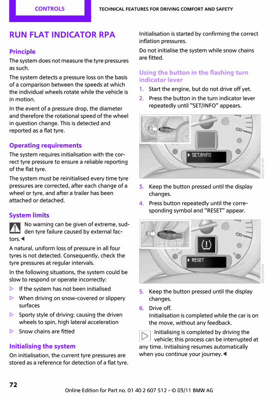
CONTROLS Technical features for driving comfort and safety
72
Run Flat Indicator RPA
PrincipleThe system does not measure the tyre pressures as such.
The system detects a pressure loss on the basis of a comparison between the speeds at which the individual wheels rotate while the vehicle is in motion.
In the event of a pressure drop, the diameter and therefore the rotational speed of the wheel in question change. This is detected and reported as a flat tyre.
Operating requirementsThe system requires initialisation with the cor-rect tyre pressure to ensure a reliable reporting of the flat tyre.
The system must be reinitialised every time tyre pressures are corrected, after each change of a wheel or tyre, and after a trailer has been attached or detached.
System limitsNo warning can be given of extreme, sud-den tyre failure caused by external fac-
tors.<
A natural, uniform loss of pressure in all four tyres is not detected. Consequently, check the tyre pressures at regular intervals.
In the following situations, the system could be slow to respond or operate incorrectly:
> If the system has not been initialised
> When driving on snow-covered or slippery surfaces
> Sporty style of driving: causing the driven wheels to spin, high lateral acceleration
> Snow chains are fitted
Initialising the systemOn initialisation, the current tyre pressures are stored as a reference for detection of a flat tyre.
Initialisation is started by confirming the correct inflation pressures.
Do not initialise the system while snow chains are fitted.
Using the button in the flashing turn indicator lever1. Start the engine, but do not drive off yet.
2. Press the button in the turn indicator lever repeatedly until "SET/INFO" appears.
3. Keep the button pressed until the display changes.
4. Press button repeatedly until the corre-sponding symbol and "RESET" appear.
5. Keep the button pressed until the display changes.
6. Drive off.Initialisation is completed while the car is on the move, without any feedback.
Initialising is completed by driving the vehicle; this process can be interrupted at
any time. Initialising resumes automatically when you continue your journey.<
Technical features for driving comfort and safety CONTROLS
73
Indication of a flat tyreThe warning lights come on in red. In addition a warning signal is heard.
There is a flat tyre or substantial loss of tyre pressure.
1. Reduce your speed and cautiously stop the car. Avoid violent or sudden braking and steering manoeuvres.
2. Check whether your vehicle is equipped with normal tyres or with run-flat tyres*.
The symbol identifying run-flat tyres, see page 143, is a circle with the letters RSC on the sidewall.
If the car is not fitted with run-flat tyres do not continue driving. Any attempt to drive
on can result in a serious accident.<
Dynamic Stability Control DSC is switched on when a flat tyre is reported.
What to do in the event of a flat tyre
Normal tyres*1. Identify the damaged tyres.
To do this, check the inflation pressure in all four tyres.You can do this using the inflation pressure display in the mobility system, page 161.
If all four tyres are inflated to the correct pressures, the Run Flat Indicator might not have been initialised. Initialise the system.
If you cannot tell which wheel is damaged, please contact Service.
2. Repair the damaged tyre with the mobility system, see page 161.
Run-flat tyres*If a tyre has punctured you can continue your journey, driving at speeds up to a maximum of 80 km/h, approx. 50 mph.
Continuing to drive with a punctureIf you continue a journey with a flat tyre:
1. Avoid violent or sudden braking and steer-ing manoeuvres.
2. Do not exceed a speed of 80 km/h, approx. 50 mph, after this.
3. Check the pressure in all four tyres at the next opportunity.
If all four tyres are inflated to the correct pressures, the Run Flat Indicator might not have been initialised. Initialise the system.
Maximum possible distance with tyres entirely deflated:
The maximum possible distance is determined by load and stress to which the vehicle is exposed during travel.
In the case of average load, the possible dis-tance is approx. 80 km, approx. 50 miles.
The vehicle's handling characteristics change when driving with damaged tyres. Examples include the vehicle swerving more when brak-ing, braking distances increasing and modified self-steering response. Modify your driving style accordingly. Avoid sudden steering movements or driving over obstacles such as kerbs, holes in the road, etc.
As the stress to which the vehicle is exposed is an essential factor in the possible distance that can be travelled with deflated tyres, this dis-tance can be reduced dependent upon speed, road conditions, outside temperature, stress, etc. Conversely, it can be increased by adopting a more conservative driving style.
Drive with caution and do not exceed a speed of 80 km/h, approx. 50 mph.
In the event of a loss of tyre inflation pressure driving characteristics change, e.g. reduced track stability during braking, longer braking dis-tance and different self-steering properties.<
When towing a trailer, heavy trailers in particular may start to snake. Therefore do
not exceed a speed of 60 km/h, approx. 35 mph, otherwise there is a risk of accident.<
Vibration or loud noises while driving may be an indication that the tyre has finally
failed. Reduce speed and stop, otherwise parts
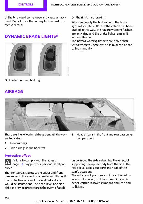
CONTROLS Technical features for driving comfort and safety
74
of the tyre could come loose and cause an acci-dent. Do not drive the car any further and con-tact Service.<
Dynamic brake lights*
On the left: normal braking.
On the right: hard braking.
When you apply the brakes hard, the brake lights of your MINI flash. If the vehicle has been braked in this way, the hazard warning flashers are activated and the brake lights remain lit without flashing. The hazard warning flashers are only deacti-vated when you accelerate again, or can be can-celled manually.
Airbags
There are the following airbags beneath the cov-ers indicated:
1 Front airbags
2 Side airbags in the backrest
3 Head airbags in the front and rear passenger compartment
Protective effectFailure to comply with the notes on page 32 may put your personal safety at
risk.<
The front airbags protect the driver and front passenger in the event of a head-on collision, if the protective action of the seat belts alone would be insufficient. The head-level and side airbags provide protection in the event of a side-
on collision. The side airbag has the effect of supporting the upper body from the side. The head-level airbag supports the head of the seat's occupant.The airbags will purposely not be activated by every collision, e.g. not by more minor acci-dents, certain rollover situations and rear-end collisions.
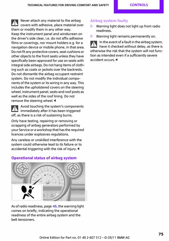
Technical features for driving comfort and safety CONTROLS
75
Never attach any material to the airbag covers with adhesive, place material over
them or modify them in any other way.Keep the instrument panel and windscreen on the driver's side clear, i.e. do not affix adhesive films or coverings, nor mount holders e.g. for a navigation device or mobile phone, in that area.Do not fit any protective covers, seat cushions or other objects to the front seats unless they have specifically been approved for use on seats with integral side airbags. Do not hang items of cloth-ing such as coats or jackets over the backrests. Do not dismantle the airbag occupant restraint system. Do not modify the individual compo-nents of the system or its wiring in any way. This includes the upholstered covers on the steering wheel, instrument panel, seats and roof posts as well as the sides of the roof lining. Do not remove the steering wheel.<
Avoid touching the system's components immediately after it has been triggered
off, as there is a risk of sustaining burns.
Only have testing, repairing or removing or scrapping of airbag generators performed by your Service or a workshop that has the required licences under explosives regulations.
Any careless or unskilled interference with the system could otherwise lead to its failure or to accidental triggering with the risk of injury.<
Operational status of airbag system
As of radio readiness, page 46, the warning light comes on briefly, indicating the operational readiness of the entire airbag system and the belt tensioners.
Airbag system faulty> Warning light does not light up from radio
readiness.
> Warning light remains permanently on.
In the event of a fault in the airbag system, have it checked without delay, as there is
otherwise the risk that the system will not func-tion as intended even if a sufficiently severe accident occurs.<
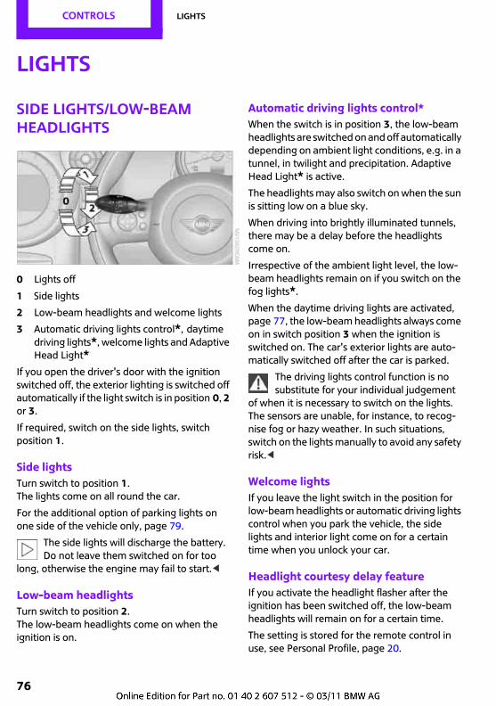
CONTROLS Lights
76
Lights
Side lights/low-beam headlights
0 Lights off
1 Side lights
2 Low-beam headlights and welcome lights
3 Automatic driving lights control*, daytime driving lights*, welcome lights and Adaptive Head Light*
If you open the driver's door with the ignition switched off, the exterior lighting is switched off automatically if the light switch is in position 0, 2 or 3.
If required, switch on the side lights, switch position 1.
Side lightsTurn switch to position 1. The lights come on all round the car.
For the additional option of parking lights on one side of the vehicle only, page 79.
The side lights will discharge the battery. Do not leave them switched on for too
long, otherwise the engine may fail to start.<
Low-beam headlightsTurn switch to position 2.The low-beam headlights come on when the ignition is on.
Automatic driving lights control*When the switch is in position 3, the low-beam headlights are switched on and off automatically depending on ambient light conditions, e.g. in a tunnel, in twilight and precipitation. Adaptive Head Light* is active.
The headlights may also switch on when the sun is sitting low on a blue sky.
When driving into brightly illuminated tunnels, there may be a delay before the headlights come on.
Irrespective of the ambient light level, the low-beam headlights remain on if you switch on the fog lights*.
When the daytime driving lights are activated, page 77, the low-beam headlights always come on in switch position 3 when the ignition is switched on. The car's exterior lights are auto-matically switched off after the car is parked.
The driving lights control function is no substitute for your individual judgement
of when it is necessary to switch on the lights. The sensors are unable, for instance, to recog-nise fog or hazy weather. In such situations, switch on the lights manually to avoid any safety risk.<
Welcome lightsIf you leave the light switch in the position for low-beam headlights or automatic driving lights control when you park the vehicle, the side lights and interior light come on for a certain time when you unlock your car.
Headlight courtesy delay featureIf you activate the headlight flasher after the ignition has been switched off, the low-beam headlights will remain on for a certain time.
The setting is stored for the remote control in use, see Personal Profile, page 20.
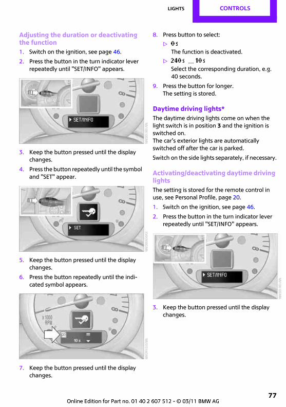
Lights CONTROLS
77
Adjusting the duration or deactivating the function1. Switch on the ignition, see page 46.
2. Press the button in the turn indicator lever repeatedly until "SET/INFO" appears.
3. Keep the button pressed until the display changes.
4. Press the button repeatedly until the symbol and "SET" appear.
5. Keep the button pressed until the display changes.
6. Press the button repeatedly until the indi-cated symbol appears.
7. Keep the button pressed until the display changes.
8. Press button to select:
>The function is deactivated.
> …Select the corresponding duration, e.g. 40 seconds.
9. Press the button for longer.The setting is stored.
Daytime driving lights*The daytime driving lights come on when the light switch is in position 3 and the ignition is switched on.The car's exterior lights are automatically switched off after the car is parked.
Switch on the side lights separately, if necessary.
Activating/deactivating daytime driving lightsThe setting is stored for the remote control in use, see Personal Profile, page 20.
1. Switch on the ignition, see page 46.
2. Press the button in the turn indicator lever repeatedly until "SET/INFO" appears.
3. Keep the button pressed until the display changes.
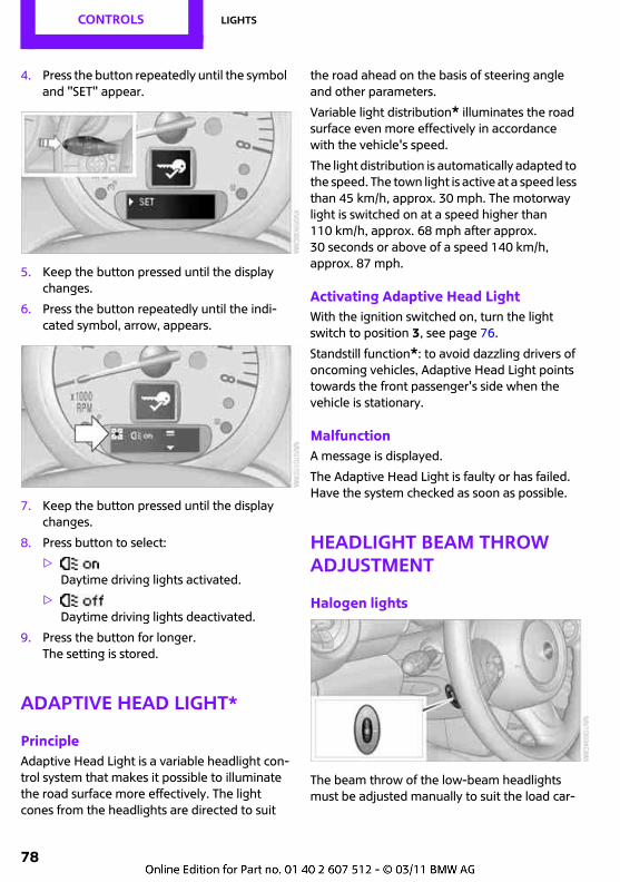
CONTROLS Lights
78
4. Press the button repeatedly until the symbol and "SET" appear.
5. Keep the button pressed until the display changes.
6. Press the button repeatedly until the indi-cated symbol, arrow, appears.
7. Keep the button pressed until the display changes.
8. Press button to select:
>Daytime driving lights activated.
>Daytime driving lights deactivated.
9. Press the button for longer.The setting is stored.
Adaptive Head Light*
PrincipleAdaptive Head Light is a variable headlight con-trol system that makes it possible to illuminate the road surface more effectively. The light cones from the headlights are directed to suit
the road ahead on the basis of steering angle and other parameters.
Variable light distribution* illuminates the road surface even more effectively in accordance with the vehicle's speed.
The light distribution is automatically adapted to the speed. The town light is active at a speed less than 45 km/h, approx. 30 mph. The motorway light is switched on at a speed higher than 110 km/h, approx. 68 mph after approx. 30 seconds or above of a speed 140 km/h, approx. 87 mph.
Activating Adaptive Head LightWith the ignition switched on, turn the light switch to position 3, see page 76.
Standstill function*: to avoid dazzling drivers of oncoming vehicles, Adaptive Head Light points towards the front passenger's side when the vehicle is stationary.
MalfunctionA message is displayed.
The Adaptive Head Light is faulty or has failed. Have the system checked as soon as possible.
Headlight beam throw adjustment
Halogen lights
The beam throw of the low-beam headlights must be adjusted manually to suit the load car-
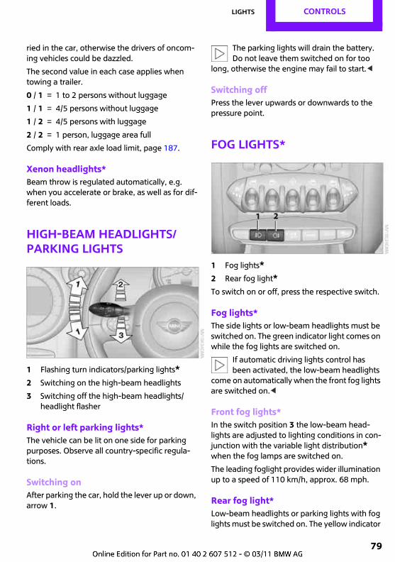
Lights CONTROLS
79
ried in the car, otherwise the drivers of oncom-ing vehicles could be dazzled.
The second value in each case applies when towing a trailer.
0 / 1 = 1 to 2 persons without luggage
1 / 1 = 4/5 persons without luggage
1 / 2 = 4/5 persons with luggage
2 / 2 = 1 person, luggage area full
Comply with rear axle load limit, page 187.
Xenon headlights*Beam throw is regulated automatically, e.g. when you accelerate or brake, as well as for dif-ferent loads.
High-beam headlights/parking lights
1 Flashing turn indicators/parking lights*2 Switching on the high-beam headlights
3 Switching off the high-beam headlights/headlight flasher
Right or left parking lights*The vehicle can be lit on one side for parking purposes. Observe all country-specific regula-tions.
Switching onAfter parking the car, hold the lever up or down, arrow 1.
The parking lights will drain the battery. Do not leave them switched on for too
long, otherwise the engine may fail to start.<
Switching offPress the lever upwards or downwards to the pressure point.
Fog lights*
1 Fog lights*2 Rear fog light*To switch on or off, press the respective switch.
Fog lights*The side lights or low-beam headlights must be switched on. The green indicator light comes on while the fog lights are switched on.
If automatic driving lights control has been activated, the low-beam headlights
come on automatically when the front fog lights are switched on.<
Front fog lights*In the switch position 3 the low-beam head-lights are adjusted to lighting conditions in con-junction with the variable light distribution* when the fog lamps are switched on.
The leading foglight provides wider illumination up to a speed of 110 km/h, approx. 68 mph.
Rear fog light*Low-beam headlights or parking lights with fog lights must be switched on. The yellow indicator
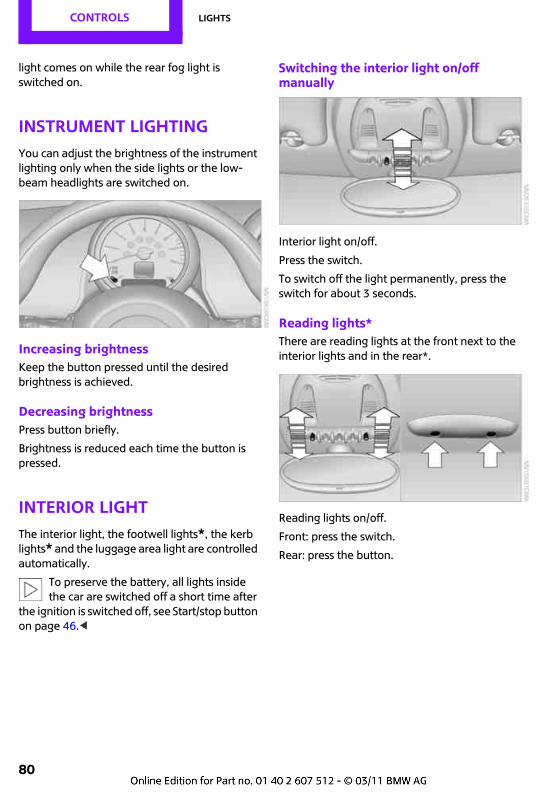
CONTROLS Lights
80
light comes on while the rear fog light is switched on.
Instrument lightingYou can adjust the brightness of the instrument lighting only when the side lights or the low-beam headlights are switched on.
Increasing brightnessKeep the button pressed until the desired brightness is achieved.
Decreasing brightnessPress button briefly.
Brightness is reduced each time the button is pressed.
Interior lightThe interior light, the footwell lights*, the kerb lights* and the luggage area light are controlled automatically.
To preserve the battery, all lights inside the car are switched off a short time after
the ignition is switched off, see Start/stop button on page 46.<
Switching the interior light on/off manually
Interior light on/off.
Press the switch.
To switch off the light permanently, press the switch for about 3 seconds.
Reading lights*There are reading lights at the front next to the interior lights and in the rear*.
Reading lights on/off.
Front: press the switch.
Rear: press the button.
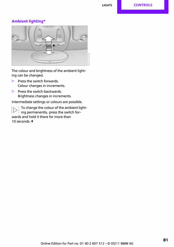
Lights CONTROLS
81
Ambient lighting*
The colour and brightness of the ambient light-ing can be changed.
> Press the switch forwards.Colour changes in increments.
> Press the switch backwards.Brightness changes in increments.
Intermediate settings or colours are possible.
To change the colour of the ambient light-ing permanently, press the switch for-
wards and hold it there for more than 10 seconds.<
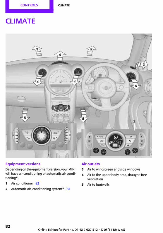
CONTROLS Climate
82
Climate
Equipment versionsDepending on the equipment version, your MINI will have air conditioning or automatic air condi-tioning*.
1 Air conditioner 83
2 Automatic air-conditioning system* 84
Air outlets3 Air to windscreen and side windows
4 Air to the upper body area, draught-free ventilation
5 Air to footwells
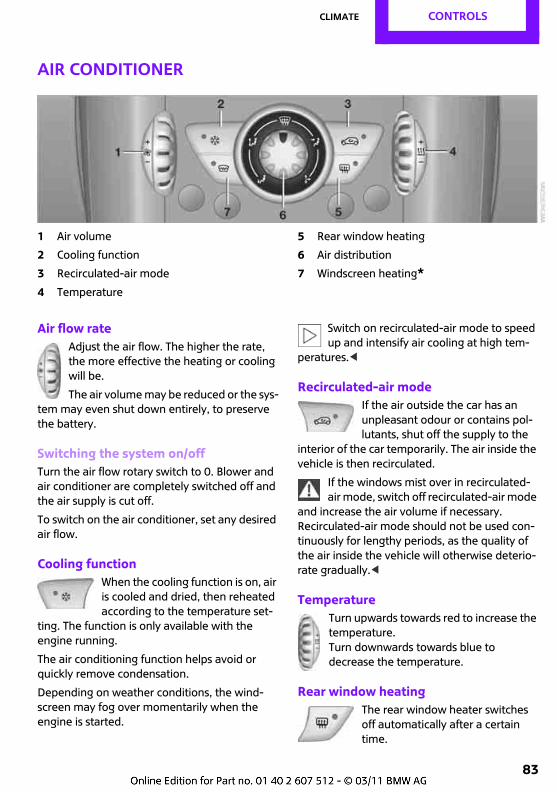
Climate CONTROLS
83
Air conditioner
1 Air volume
2 Cooling function
3 Recirculated-air mode
4 Temperature
5 Rear window heating
6 Air distribution
7 Windscreen heating*
Air flow rateAdjust the air flow. The higher the rate, the more effective the heating or cooling will be.
The air volume may be reduced or the sys-tem may even shut down entirely, to preserve the battery.
Switching the system on/offTurn the air flow rotary switch to 0. Blower and air conditioner are completely switched off and the air supply is cut off.
To switch on the air conditioner, set any desired air flow.
Cooling functionWhen the cooling function is on, air is cooled and dried, then reheated according to the temperature set-
ting. The function is only available with the engine running.
The air conditioning function helps avoid or quickly remove condensation.
Depending on weather conditions, the wind-screen may fog over momentarily when the engine is started.
Switch on recirculated-air mode to speed up and intensify air cooling at high tem-
peratures.<
Recirculated-air modeIf the air outside the car has an unpleasant odour or contains pol-lutants, shut off the supply to the
interior of the car temporarily. The air inside the vehicle is then recirculated.
If the windows mist over in recirculated-air mode, switch off recirculated-air mode
and increase the air volume if necessary.Recirculated-air mode should not be used con-tinuously for lengthy periods, as the quality of the air inside the vehicle will otherwise deterio-rate gradually.<
TemperatureTurn upwards towards red to increase the temperature.Turn downwards towards blue to decrease the temperature.
Rear window heatingThe rear window heater switches off automatically after a certain time.
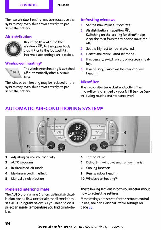
CONTROLS Climate
84
The rear window heating may be reduced or the system may even shut down entirely, to pre-serve the battery.
Air distributionDirect the flow of air to the windows , to the upper body area or to the footwell . Intermediate settings are possible.
Windscreen heating*The windscreen heating is switched off automatically after a certain time.
The windscreen heating may be reduced or the system may even shut down entirely, to pre-serve the battery.
Defrosting windows1. Set the maximum air flow rate.
2. Air distribution in position .Switching on the cooling function* helps clear the mist from the windows more rap-idly.
3. Set the highest temperature, red.
4. Deactivate recirculated-air mode.
5. If necessary, switch on the windscreen heat-ing.
6. If necessary, switch on the rear window heating.
MicrofilterThe micro-filter traps dust and pollen. The micro-filter is changed by your MINI Service Cen-tre during routine maintenance work.
Automatic air-conditioning system*
1 Adjusting air volume manually
2 AUTO program
3 Recirculated-air mode
4 Maximum cooling effect
5 Manual air distribution
6 Temperature
7 Defrosting windows and removing mist
8 Cooling function
9 Rear window heating
10 Windscreen heating*
Preferred interior climateThe AUTO programme 2 offers optimal air distri-bution and air flow rate for almost all conditions, see AUTO program below. All you need to do is select an inside temperature you find comforta-ble.
The following sections inform you in detail about how to adjust the settings.
Most settings are stored for the remote control in use, see also Personal Profile settings on page 20.
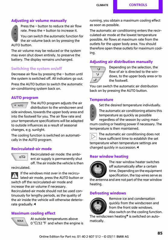
Climate CONTROLS
85
Adjusting air volume manuallyPress the – button to reduce the air flow rate. Press the + button to increase it.
You can switch the automatic function for the air volume back on by pressing the
AUTO button.
The air volume may be reduced or the system may even shut down entirely, to preserve the battery. The display remains unchanged.
Switching the system on/offDecrease air flow by pressing the – button until the system is switched off. All indicators go out.
Press the AUTO button to switch the automatic air-conditioning system back on.
AUTO programThe AUTO program adjusts the air distribution to the windscreen and
side windows, towards the upper body area and into the footwell for you. The air flow rate and your temperature specifications will be adapted to outside influences as a result of seasonal changes, e.g. sunlight.
The cooling function is switched on automati-cally in the AUTO program.
Recirculated-air modeRecirculated-air mode: the ambi-ent air supply is permanently shut off. The air inside the vehicle is then
recirculated.
If the windows mist over in the recircu-lated-air mode, press the AUTO button or
switch off the recirculated-air mode and increase the air volume if necessary.Recirculated-air mode should not be used con-tinuously for lengthy periods, as the quality of the air inside the vehicle will otherwise deterio-rate gradually.<
Maximum cooling effectAt outside temperatures above 06/327 and when the engine is
running, you obtain a maximum cooling effect as soon as possible.
The automatic air conditioning enters the recir-culated-air mode at the lowest temperature possible. Air flows at maximum rate from the outlets for the upper body area. You should therefore open these outlets for maximum cool-ing.
Adjusting air distribution manuallyDepending on the selection, the flow of air is directed to the win-dows, to the upper body area or to the footwell.
You can switch the automatic air distribution back on by pressing the AUTO button.
TemperatureSet the desired temperature individually.
The automatic air conditioning attains this temperature as quickly as possible regardless of the season by using maxi-
mum cooling or heating power if necessary. The temperature is then maintained.
The automatic air conditioning does not have sufficient time to establish the set
temperature when temperature settings are changed quickly in succession.<
Rear window heatingThe rear window heater switches off automatically after a certain time. Depending on the equipment specification, the top wires serve as
the antenna and are not part of the rear window heating.
Defrosting windowsRemove ice and condensation quickly from the windscreen and from the front side windows. Also switch on the cooling function.
The windscreen heating* is switched on auto-matically.
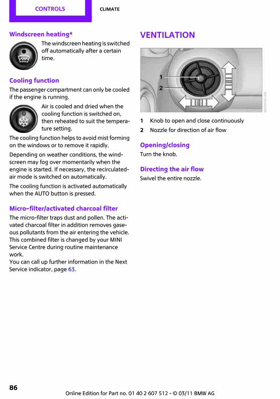
CONTROLS Climate
86
Windscreen heating*The windscreen heating is switched off automatically after a certain time.
Cooling functionThe passenger compartment can only be cooled if the engine is running.
Air is cooled and dried when the cooling function is switched on, then reheated to suit the tempera-ture setting.
The cooling function helps to avoid mist forming on the windows or to remove it rapidly.
Depending on weather conditions, the wind-screen may fog over momentarily when the engine is started. If necessary, the recirculated-air mode is switched on automatically.
The cooling function is activated automatically when the AUTO button is pressed.
Micro-filter/activated charcoal filterThe micro-filter traps dust and pollen. The acti-vated charcoal filter in addition removes gase-ous pollutants from the air entering the vehicle. This combined filter is changed by your MINI Service Centre during routine maintenance work. You can call up further information in the Next Service indicator, page 63.
Ventilation
1 Knob to open and close continuously
2 Nozzle for direction of air flow
Opening/closingTurn the knob.
Directing the air flowSwivel the entire nozzle.
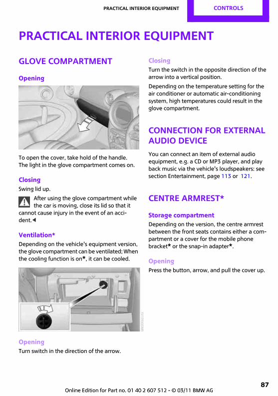
Practical interior equipment CONTROLS
87
Practical interior equipment
Glove compartment
Opening
To open the cover, take hold of the handle. The light in the glove compartment comes on.
ClosingSwing lid up.
After using the glove compartment while the car is moving, close its lid so that it
cannot cause injury in the event of an acci-dent.<
Ventilation*Depending on the vehicle's equipment version, the glove compartment can be ventilated; When the cooling function is on*, it can be cooled.
OpeningTurn switch in the direction of the arrow.
ClosingTurn the switch in the opposite direction of the arrow into a vertical position.
Depending on the temperature setting for the air conditioner or automatic air-conditioning system, high temperatures could result in the glove compartment.
Connection for external audio deviceYou can connect an item of external audio equipment, e.g. a CD or MP3 player, and play back music via the vehicle's loudspeakers: see section Entertainment, page 113 or 121.
Centre armrest*
Storage compartmentDepending on the version, the centre armrest between the front seats contains either a com-partment or a cover for the mobile phone bracket* or the snap-in adapter*.
OpeningPress the button, arrow, and pull the cover up.
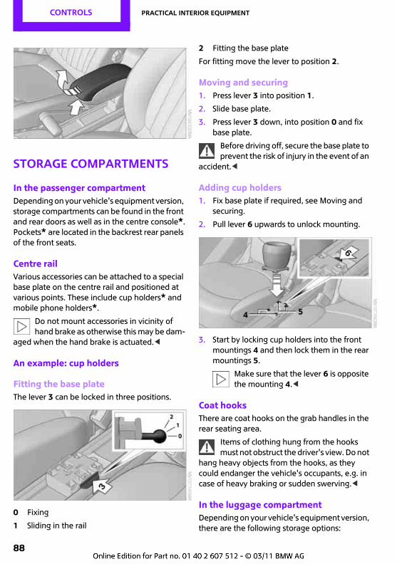
CONTROLS Practical interior equipment
88
Storage compartments
In the passenger compartmentDepending on your vehicle's equipment version, storage compartments can be found in the front and rear doors as well as in the centre console*.Pockets* are located in the backrest rear panels of the front seats.
Centre railVarious accessories can be attached to a special base plate on the centre rail and positioned at various points. These include cup holders* and mobile phone holders*.
Do not mount accessories in vicinity of hand brake as otherwise this may be dam-
aged when the hand brake is actuated.<
An example: cup holders
Fitting the base plateThe lever 3 can be locked in three positions.
0 Fixing
1 Sliding in the rail
2 Fitting the base plate
For fitting move the lever to position 2.
Moving and securing1. Press lever 3 into position 1.
2. Slide base plate.
3. Press lever 3 down, into position 0 and fix base plate.
Before driving off, secure the base plate to prevent the risk of injury in the event of an
accident.<
Adding cup holders1. Fix base plate if required, see Moving and
securing.
2. Pull lever 6 upwards to unlock mounting.
3. Start by locking cup holders into the front mountings 4 and then lock them in the rear mountings 5.
Make sure that the lever 6 is opposite the mounting 4.<
Coat hooksThere are coat hooks on the grab handles in the rear seating area.
Items of clothing hung from the hooks must not obstruct the driver's view. Do not
hang heavy objects from the hooks, as they could endanger the vehicle's occupants, e.g. in case of heavy braking or sudden swerving.<
In the luggage compartmentDepending on your vehicle's equipment version, there are the following storage options:
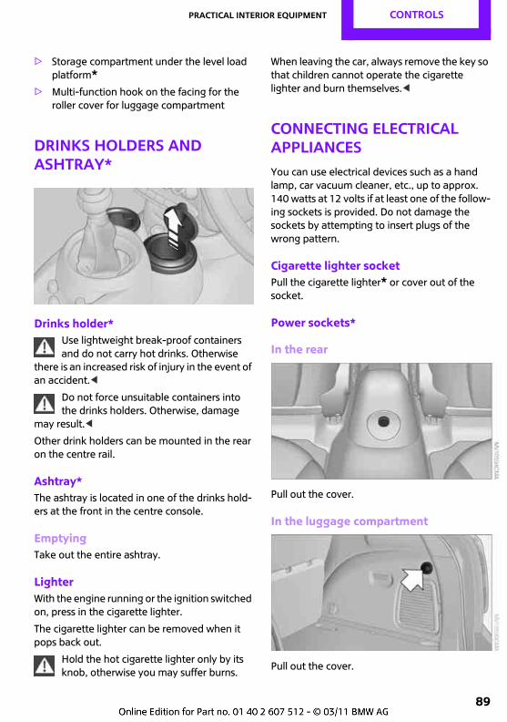
Practical interior equipment CONTROLS
89
> Storage compartment under the level load platform*
> Multi-function hook on the facing for the roller cover for luggage compartment
Drinks holders and ashtray*
Drinks holder*Use lightweight break-proof containers and do not carry hot drinks. Otherwise
there is an increased risk of injury in the event of an accident.<
Do not force unsuitable containers into the drinks holders. Otherwise, damage
may result.<
Other drink holders can be mounted in the rear on the centre rail.
Ashtray*The ashtray is located in one of the drinks hold-ers at the front in the centre console.
EmptyingTake out the entire ashtray.
LighterWith the engine running or the ignition switched on, press in the cigarette lighter.
The cigarette lighter can be removed when it pops back out.
Hold the hot cigarette lighter only by its knob, otherwise you may suffer burns.
When leaving the car, always remove the key so that children cannot operate the cigarette lighter and burn themselves.<
Connecting electrical appliancesYou can use electrical devices such as a hand lamp, car vacuum cleaner, etc., up to approx. 140 watts at 12 volts if at least one of the follow-ing sockets is provided. Do not damage the sockets by attempting to insert plugs of the wrong pattern.
Cigarette lighter socketPull the cigarette lighter* or cover out of the socket.
Power sockets*
In the rear
Pull out the cover.
In the luggage compartment
Pull out the cover.
Drive Me.
OVERVIEW
CONTROLS
Entertainment
COMMUNICATION
MOBILITY
REFERENCE
DRIVING HINTS
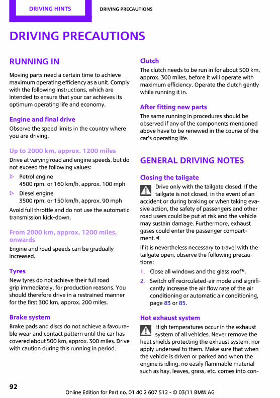
DRIVING HINTS Driving precautions
92
Driving precautions
Running inMoving parts need a certain time to achieve maximum operating efficiency as a unit. Comply with the following instructions, which are intended to ensure that your car achieves its optimum operating life and economy.
Engine and final driveObserve the speed limits in the country where you are driving.
Up to 2000 km, approx. 1200 milesDrive at varying road and engine speeds, but do not exceed the following values:
> Petrol engine 4500 rpm, or 160 km/h, approx. 100 mph
> Diesel engine 3500 rpm, or 150 km/h, approx. 90 mph
Avoid full throttle and do not use the automatic transmission kick-down.
From 2000 km, approx. 1200 miles, onwardsEngine and road speeds can be gradually increased.
TyresNew tyres do not achieve their full road grip immediately, for production reasons. You should therefore drive in a restrained manner for the first 300 km, approx. 200 miles.
Brake systemBrake pads and discs do not achieve a favoura-ble wear and contact pattern until the car has covered about 500 km, approx. 300 miles. Drive with caution during this running in period.
ClutchThe clutch needs to be run in for about 500 km, approx. 300 miles, before it will operate with maximum efficiency. Operate the clutch gently while running it in.
After fitting new partsThe same running in procedures should be observed if any of the components mentioned above have to be renewed in the course of the car's operating life.
General driving notes
Closing the tailgateDrive only with the tailgate closed. If the tailgate is not closed, in the event of an
accident or during braking or when taking eva-sive action, the safety of passengers and other road users could be put at risk and the vehicle may sustain damage. Furthermore, exhaust gases could enter the passenger compart-ment.<
If it is nevertheless necessary to travel with the tailgate open, observe the following precau-tions:
1. Close all windows and the glass roof*.
2. Switch off recirculated-air mode and signifi-cantly increase the air flow rate of the air conditioning or automatic air conditioning, page 83 or 85.
Hot exhaust systemHigh temperatures occur in the exhaust system of all vehicles. Never remove the
heat shields protecting the exhaust system, nor apply underseal to them. Make sure that when the vehicle is driven or parked and when the engine is idling, no easily flammable material such as hay, leaves, grass, etc. comes into con-
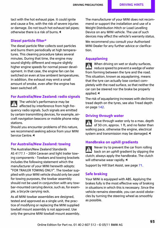
Driving precautions DRIVING HINTS
93
tact with the hot exhaust pipe. It could ignite and cause a fire, with the risk of severe injuries or damage. Do not touch hot exhaust tail pipes; otherwise there is a risk of burns.<
Diesel particle filter*The diesel particle filter collects soot particles and burns them periodically at high tempera-tures. This cleaning procedure takes several minutes. During that time, the engine may sound slightly different and require slightly higher engine speeds for normal power devel-opment. In that case, the engine fan can be switched on even at low ambient temperatures. In addition, the exhaust may emit a small amount of smoke, even after the engine has been switched off.
For Australia/New Zealand: radio signalsThe vehicle's performance may be affected by interference from high fre-
quency radio signals. Such signals are emitted by certain transmitting devices, for example, air-craft navigation beacons or mobile phone relay stations.Should you encounter problems of this nature, we recommend seeking advice from your MINI Service Centre.<
For Australia/New Zealand: towingThe Australian/New Zealand Standards AS 4177.1 - 2004 Caravan and light trailer tow-ing components - Towbars and towing brackets includes the following statement which the manufacturer of your MINI herewith adopts: "FOR TRAILER TOWING ONLY". The towbar sup-plied with your MINI vehicle should only be used for towing purposes, the towbar assembly should not be used in conjunction with any tow-bar-mounted carrying device, such as, for exam-ple, a bicycle carrying rack.
As all MINI towbar assemblies are designed, tested and approved as a single unit, the prac-tice of modifying or replacing the MINI supplied towball mount assembly is not approved. Use only the genuine MINI towball mount assembly.
The manufacturer of your MINI does not recom-mend or support the installation and use of a Weight Distribution Hitch or Load Levelling Device on any MINI vehicle. The use of such devices may affect the vehicle's warranty status.
We recommend you consult your Authorised MINI Dealer for any further advice or clarifica-tion.
AquaplaningWhen driving on wet or slushy surfaces, reduce speed to prevent a wedge of water
from forming between the tyre and the road. This situation, known as aquaplaning, means that the tyre can actually lose contact com-pletely with the road surface, so that neither the car can be steered nor the brake be properly applied.<
The risk of aquaplaning increases with declining tread depth on the tyres, see also Tread depth on page 142.
Driving through waterDrive through water only to a max. depth of 30 cm, approx. 1 ft, and no faster than
walking pace, otherwise the engine, electrical system and transmission may be damaged.<
Handbrake on uphill gradientsNever try to prevent the car from rolling back on an uphill gradient by slipping the
clutch; always apply the handbrake. The clutch will otherwise wear rapidly.<
Support by Hill Start Assist, see page 71.
Safe brakingYour MINI is equipped with ABS. Applying the brakes fully is the most effective way of braking in situations in which this is necessary. Since the vehicle remains steerable, you can avoid obsta-cles by turning the steering wheel as smoothly as possible.
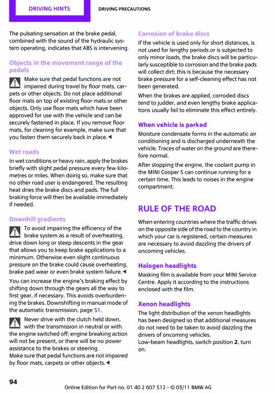
DRIVING HINTS Driving precautions
94
The pulsating sensation at the brake pedal, combined with the sound of the hydraulic sys-tem operating, indicates that ABS is intervening.
Objects in the movement range of the pedals
Make sure that pedal functions are not impaired during travel by floor mats, car-
pets or other objects. Do not place additional floor mats on top of existing floor mats or other objects. Only use floor mats which have been approved for use with the vehicle and can be securely fastened in place. If you remove floor mats, for cleaning for example, make sure that you fasten them securely back in place.<
Wet roadsIn wet conditions or heavy rain, apply the brakes briefly with slight pedal pressure every few kilo-metres or miles. When doing so, make sure that no other road user is endangered. The resulting heat dries the brake discs and pads. The full braking force will then be available immediately if needed.
Downhill gradientsTo avoid impairing the efficiency of the brake system as a result of overheating,
drive down long or steep descents in the gear that allows you to keep brake applications to a minimum. Otherwise even slight continuous pressure on the brake could cause overheating, brake pad wear or even brake system failure.<
You can increase the engine's braking effect by shifting down through the gears all the way to first gear, if necessary. This avoids overburden-ing the brakes. Downshifting in manual mode of the automatic transmission, page 51.
Never drive with the clutch held down, with the transmission in neutral or with
the engine switched off; engine breaking action will not be present, or there will be no power assistance to the brakes or steering. Make sure that pedal functions are not impaired by floor mats, carpets or other objects.<
Corrosion of brake discsIf the vehicle is used only for short distances, is not used for lengthy periods or is subjected to only minor loads, the brake discs will be particu-larly susceptible to corrosion and the brake pads will collect dirt; this is because the necessary brake pressure for a self-cleaning effect has not been generated.
When the brakes are applied, corroded discs tend to judder, and even lengthy brake applica-tions usually fail to eliminate this effect entirely.
When vehicle is parkedMoisture condensate forms in the automatic air conditioning and is discharged underneath the vehicle. Traces of water on the ground are there-fore normal.
After stopping the engine, the coolant pump in the MINI Cooper S can continue running for a certain time. This leads to noises in the engine compartment.
Rule of the roadWhen entering countries where the traffic drives on the opposite side of the road to the country in which your car is registered, certain measures are necessary to avoid dazzling the drivers of oncoming vehicles.
Halogen headlightsMasking film is available from your MINI Service Centre. Apply it according to the instructions enclosed with the film.
Xenon headlightsThe light distribution of the xenon headlights has been designed so that additional measures do not need to be taken to avoid dazzling the drivers of oncoming vehicles.Low-beam headlights, switch position 2, turn on.
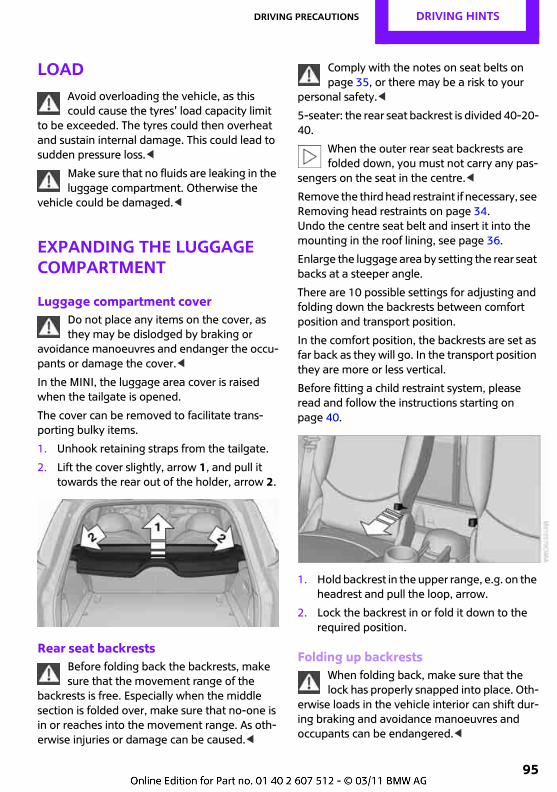
Driving precautions DRIVING HINTS
95
LoadAvoid overloading the vehicle, as this could cause the tyres' load capacity limit
to be exceeded. The tyres could then overheat and sustain internal damage. This could lead to sudden pressure loss.<
Make sure that no fluids are leaking in the luggage compartment. Otherwise the
vehicle could be damaged.<
Expanding the luggage compartment
Luggage compartment coverDo not place any items on the cover, as they may be dislodged by braking or
avoidance manoeuvres and endanger the occu-pants or damage the cover.<
In the MINI, the luggage area cover is raised when the tailgate is opened.
The cover can be removed to facilitate trans-porting bulky items.
1. Unhook retaining straps from the tailgate.
2. Lift the cover slightly, arrow 1, and pull it towards the rear out of the holder, arrow 2.
Rear seat backrestsBefore folding back the backrests, make sure that the movement range of the
backrests is free. Especially when the middle section is folded over, make sure that no-one is in or reaches into the movement range. As oth-erwise injuries or damage can be caused.<
Comply with the notes on seat belts on page 35, or there may be a risk to your
personal safety.<
5-seater: the rear seat backrest is divided 40-20-40.
When the outer rear seat backrests are folded down, you must not carry any pas-
sengers on the seat in the centre.<
Remove the third head restraint if necessary, see Removing head restraints on page 34.Undo the centre seat belt and insert it into the mounting in the roof lining, see page 36.
Enlarge the luggage area by setting the rear seat backs at a steeper angle.
There are 10 possible settings for adjusting and folding down the backrests between comfort position and transport position.
In the comfort position, the backrests are set as far back as they will go. In the transport position they are more or less vertical.
Before fitting a child restraint system, please read and follow the instructions starting on page 40.
1. Hold backrest in the upper range, e.g. on the headrest and pull the loop, arrow.
2. Lock the backrest in or fold it down to the required position.
Folding up backrestsWhen folding back, make sure that the lock has properly snapped into place. Oth-
erwise loads in the vehicle interior can shift dur-ing braking and avoidance manoeuvres and occupants can be endangered.<
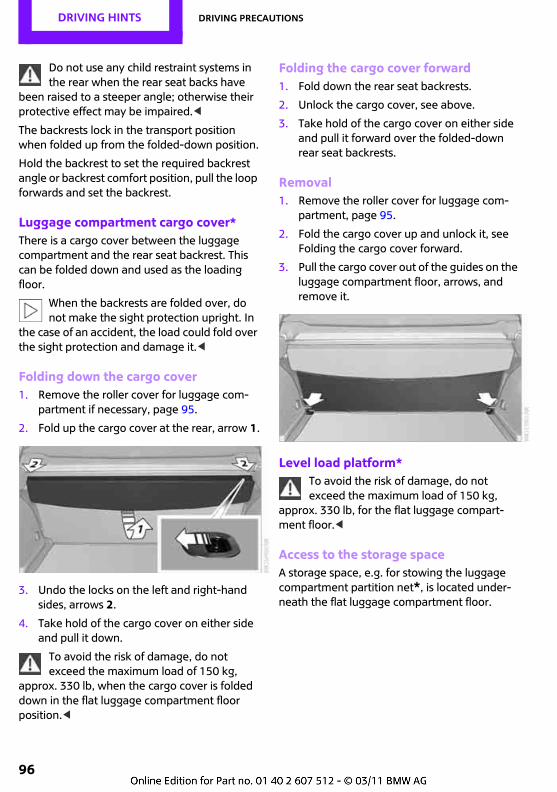
DRIVING HINTS Driving precautions
96
Do not use any child restraint systems in the rear when the rear seat backs have
been raised to a steeper angle; otherwise their protective effect may be impaired.<
The backrests lock in the transport position when folded up from the folded-down position.
Hold the backrest to set the required backrest angle or backrest comfort position, pull the loop forwards and set the backrest.
Luggage compartment cargo cover*There is a cargo cover between the luggage compartment and the rear seat backrest. This can be folded down and used as the loading floor.
When the backrests are folded over, do not make the sight protection upright. In
the case of an accident, the load could fold over the sight protection and damage it.<
Folding down the cargo cover1. Remove the roller cover for luggage com-
partment if necessary, page 95.
2. Fold up the cargo cover at the rear, arrow 1.
3. Undo the locks on the left and right-hand sides, arrows 2.
4. Take hold of the cargo cover on either side and pull it down.
To avoid the risk of damage, do not exceed the maximum load of 150 kg,
approx. 330 lb, when the cargo cover is folded down in the flat luggage compartment floor position.<
Folding the cargo cover forward1. Fold down the rear seat backrests.
2. Unlock the cargo cover, see above.
3. Take hold of the cargo cover on either side and pull it forward over the folded-down rear seat backrests.
Removal1. Remove the roller cover for luggage com-
partment, page 95.
2. Fold the cargo cover up and unlock it, see Folding the cargo cover forward.
3. Pull the cargo cover out of the guides on the luggage compartment floor, arrows, and remove it.
Level load platform*To avoid the risk of damage, do not exceed the maximum load of 150 kg,
approx. 330 lb, for the flat luggage compart-ment floor.<
Access to the storage spaceA storage space, e.g. for stowing the luggage compartment partition net*, is located under-neath the flat luggage compartment floor.
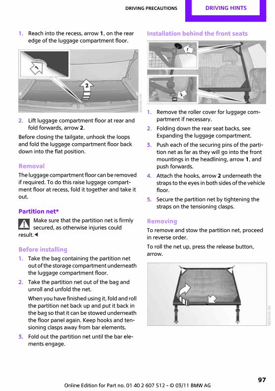
Driving precautions DRIVING HINTS
97
1. Reach into the recess, arrow 1, on the rear edge of the luggage compartment floor.
2. Lift luggage compartment floor at rear and fold forwards, arrow 2.
Before closing the tailgate, unhook the loops and fold the luggage compartment floor back down into the flat position.
RemovalThe luggage compartment floor can be removed if required. To do this raise luggage compart-ment floor at recess, fold it together and take it out.
Partition net*Make sure that the partition net is firmly secured, as otherwise injuries could
result.<
Before installing1. Take the bag containing the partition net
out of the storage compartment underneath the luggage compartment floor.
2. Take the partition net out of the bag and unroll and unfold the net.
When you have finished using it, fold and roll the partition net back up and put it back in the bag so that it can be stowed underneath the floor panel again. Keep hooks and ten-sioning clasps away from bar elements.
3. Fold out the partition net until the bar ele-ments engage.
Installation behind the front seats
1. Remove the roller cover for luggage com-partment if necessary.
2. Folding down the rear seat backs, see Expanding the luggage compartment.
3. Push each of the securing pins of the parti-tion net as far as they will go into the front mountings in the headlining, arrow 1, and push forwards.
4. Attach the hooks, arrow 2 underneath the straps to the eyes in both sides of the vehicle floor.
5. Secure the partition net by tightening the straps on the tensioning clasps.
RemovingTo remove and stow the partition net, proceed in reverse order.
To roll the net up, press the release button, arrow.
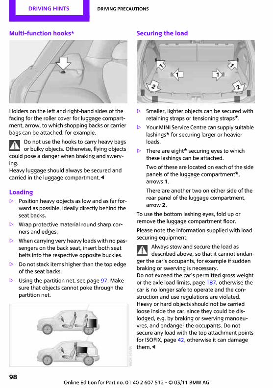
DRIVING HINTS Driving precautions
98
Multi-function hooks*
Holders on the left and right-hand sides of the facing for the roller cover for luggage compart-ment, arrow, to which shopping backs or carrier bags can be attached, for example.
Do not use the hooks to carry heavy bags or bulky objects. Otherwise, flying objects
could pose a danger when braking and swerv-ing.Heavy luggage should always be secured and carried in the luggage compartment.<
Loading> Position heavy objects as low and as far for-
ward as possible, ideally directly behind the seat backs.
> Wrap protective material round sharp cor-ners and edges.
> When carrying very heavy loads with no pas-sengers on the back seat, insert both seat belts into the respective opposite buckles.
> Do not stack items higher than the top edge of the seat backs.
> Using the partition net, see page 97. Make sure that objects cannot poke through the partition net.
Securing the load
> Smaller, lighter objects can be secured with retaining straps or tensioning straps*.
> Your MINI Service Centre can supply suitable lashings* for securing larger or heavier loads.
> There are eight* securing eyes to which these lashings can be attached.
Two of these are located on each of the side panels of the luggage compartment*, arrows 1.
There are another two on either side of the rear panel of the luggage compartment, arrow 2.
To use the bottom lashing eyes, fold up or remove the luggage compartment floor.
Please note the information supplied with load securing equipment.
Always stow and secure the load as described above, so that it cannot endan-
ger the car's occupants, for example if sudden braking or swerving is necessary. Do not exceed the car's permitted gross weight or the axle load limits, page 187, otherwise the car is no longer safe to operate and the con-struction and use regulations are violated. Heavy or hard objects should not be carried loose inside the car, since they could be dis-lodged, e.g. by braking or swerving manoeu-vres, and endanger the occupants. Do not secure any load with the top attachment points for ISOFIX, page 42, otherwise it can damage them.<
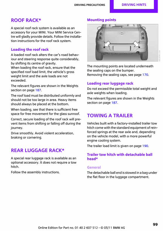
Driving precautions DRIVING HINTS
99
Roof rack*A special roof rack system is available as an accessory for your MINI. Your MINI Service Cen-tre will gladly provide details. Follow the installa-tion instructions for the roof rack system.
Loading the roof rackA loaded roof rack alters the car's road behav-iour and steering response quite considerably, by shifting its centre of gravity. When loading the roof rack, ensure that the specified roof load limit, the vehicle's gross weight limit and the axle loads are not exceeded.
The relevant figures are shown in the Weights section on page 187.
The roof load must be distributed uniformly and should not be too large in area. Heavy items should always be placed at the bottom.
When loading, see that there is sufficient free space for free movement for the glass sunroof.
Correct, secure loading of the roof rack will pre-vent items from shifting or falling off during the journey.
Drive smoothly. Avoid violent acceleration, braking or cornering.
Rear luggage rack*A special rear luggage rack is available as an optional accessory. It does not require a tow hitch.
Follow the assembly instructions.
Mounting points
The mounting points are located underneath the sealing caps on the bumper.Removing the sealing caps, see page 170.
Loading rear luggage rackDo not exceed the permissible total weight and axle weights when loading.
The relevant figures are shown in the Weights section on page 187.
Towing a trailerVehicles built with a factory-installed trailer tow hitch come with the standard equipment of rein-forced springs at the rear axle and, depending on the vehicle model, with a more powerful engine cooling system.
The trailer load limit is given on page 190.
Trailer tow hitch with detachable ball head*
GeneralThe detachable ball end is stowed in a bag under the flat floor in the luggage compartment.
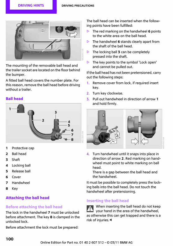
DRIVING HINTS Driving precautions
100
The mounting of the removable ball head and the trailer socket are located on the floor behind the bumper.
A fitted ball head covers the number plate. For this reason, remove the ball head before driving without a trailer.
Ball head
1 Protective cap
2 Ball head
3 Shaft
4 Locking ball
5 Release ball
6 Cover
7 Handwheel
8 Key
Attaching the ball head
Before attaching the ball headThe lock in the handwheel 7 must be unlocked before attachment. The key 8 is clamped in the unlocked lock.
Before attachment the lock must be prepared:
The ball head can be inserted when the follow-ing points have been fulfilled:
> The red marking on the handwheel 6 points to the white area on the ball head.
> The handwheel 6 stands clearly apart from the shaft of the ball head.
> The locking ball 3 can be completely pressed into the shaft.
> The key points to the symbol 'Lock open' and cannot be pulled out.
If the ball head has not been pretensioned, carry out the following steps:
1. Remove cover from lock, if required insert key.
2. Turn key clockwise.
3. Pull out handwheel in direction of arrow 1 and hold firmly.
4. Turn handwheel until it snaps into place in direction of arrow 2. Red marking on hand-wheel must point to white marking on ball head.There is a gap between the ball head and the handwheel.
It must be possible to completely press the lock-ing balls into the ball head. Do not touch the handwheel after pretensioning.
Inserting the ball headWhen inserting the ball head do not keep your hand in the area of the handwheel,
as otherwise this can get trapped and there is a risk of injuries.<
Driving precautions DRIVING HINTS
101
1. Remove the cover stopper of the mounting by pulling it downwards and stow it in the vehicle.
2. Insert the ball head from below into the mounting with the shaft and push upwards until it snaps into place.
3. Lock the lock in the handwheel.
4. Attach cover to lock.
Checking the lock is closedBefore driving with a caravan or trailer, check whether the ball head is correctly
locked, as otherwise it can lead to instability when driving and accidents.<
By shaking the ball head, make sure that this is securely mounted.
If the ball head is not securely mounted, check the following points:
> Green marking on the handwheel points to the white area on the ball head.
> Handwheel is flush against the ball head.
> The lock is closed and the key removed.
If all points have been fulfilled and the ball head is despite this not firmly mounted, do not use the trailer coupling and get it checked by Serv-ice.
Removing the ball head1. Remove cover cap from the lock.
2. Insert the key and open the lock in the hand-wheel.The key is clamped in the lock.
3. Hold ball head steady.
4. Pull out the handwheel, arrow 1 and turn in arrow direction 2, as far as it will go.
5. Take ball head out of the mounting by pull-ing downwards.
6. Insert cover stopper in the mounting.
7. Stow ball head in luggage compartment again.
Note care instructions on page 155.
Before a journey
Trailer nose weightDo not undercut the minimum trailer nose weight of 25 kg, approx. 55 lb. The nose weight limit is given on page 190. The nose weight should be kept close to this limit.
The nose weight affects the vehicle and thus increases its weight. The weight of the trailer tow hitch and the nose weight reduce the maxi-mum payload of your MINI. Please ensure that these do not cause the gross weight limit of the towing vehicle to be exceeded if a trailer is being towed.
LoadsWhen loading the trailer, make sure that the weight is kept as low as possible and stowed if possible close to the axle.
A low centre of trailer gravity makes the outfit much more stable and safe to drive.
Do not exceed either the trailer's permitted gross weight or the specified permitted towing load for the vehicle. The smaller value is the limit which should be adhered to.
Tyre pressuresCheck the vehicle's and the trailer's tyre pres-sures carefully. For the car, the tyre inflation pressures for heavy loads apply, page 142. After each correction of the tyre pressures, reinitialise the Run Flat Indicator, see page 72. For the trailer, comply with the manufacturer's specifi-cations.
Run Flat IndicatorReinitialise the Run Flat Indicator after a trailer has been attached or detached, see page 72.
Exterior mirrorsTwo exterior mirrors which bring both rear cor-ners of the trailer into your field of view are required by law. Mirrors of this kind can be
DRIVING HINTS Driving precautions
102
obtained from your MINI Service Centre as optional accessories.
Electrical consumersWhen towing a caravan, try to avoid operating electrical equipment for too long at a time, in order to limit the drain on the vehicle's battery.
The power output of the trailer's rear lights must not exceed the following values:Flashing turn indicators: 42 W each sideTail lights: 60 W each sideBrake lights: 42 W totalRear fog lights: 42 W totalReversing lights: 42 W total.
Before starting a journey, check that the trailer's rear lights are operating correctly.
As otherwise, there is a risk of endangering other road users.<
Towing a trailerAdapt your speed accordingly when tow-ing a trailer. Dependent upon design and
load, some trailers will start to snake at and above speeds of approx. 80 km/h, approx. 50 mph.<
When towing a trailer, increase the infla-tion pressure by 0.2 bar and do not
exceed speeds of 100 km/h, 60 mph, otherwise the increased axle weight could damage the tyres. Do not exceed the maximum possible inflation pressure indicated on the tyres.<
Counteracting snakingIf the trailer nevertheless begins to snake, the outfit can only be stabilised by braking hard immediately. Only attempt to steer out of the situation if this is absolutely essential, and make any steering movements as cautiously as possi-ble and without endangering other road users.
Uphill gradientsIn the interest of safety and to avoid holding up other traffic, do not attempt to climb gradients steeper than 12% when towing a trailer. If a supplementary permit for heavier trailer loads
has been obtained, the limit is 8%, see page 190.
Downhill gradientsSpecial care must be taken when descending gradients, where a trailer is more susceptible to snaking.
Before starting to descend, always change down to the next lower gear, if necessary as far as first gear, and drive down the hill slowly.
Saving fuelFuel consumption depends on various factors. Certain measures, driving style and regular maintenance can influence the fuel consump-tion and the burden on the environment.
Remove unnecessary loadsExtra weight inflates fuel consumption.
Remove add-on parts after useRemove auxiliary mirrors, roof racks and rear-mounted racks after use.
Add-on parts on the vehicle interfere with its aerodynamic performance and inflate fuel con-sumption.
Check tyre pressures regularlyCheck and, if necessary, correct tyre inflation pressures at least twice a month and before set-ting off on a longer journey.
Insufficient tyre inflation pressure enlarges the rolling resistance and thus increases fuel con-sumption and tyre wear.
Drive off immediatelyDo not warm up the engine with the car at a standstill; it is preferable to set off straight away, driving at moderate engine speeds. A cold engine will then reach its operating temperature faster.
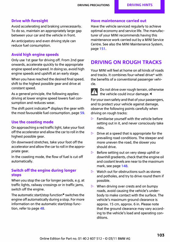
Driving precautions DRIVING HINTS
103
Drive with foresightAvoid accelerating and braking unnecessarily. To do so, maintain an appropriately large gap between your car and the vehicle in front.
An anticipatory and even driving style can reduce fuel consumption.
Avoid high engine speedsOnly use 1st gear for driving off. From 2nd gear onwards, accelerate quickly to the appropriate engine speed and speed. In doing so, avoid high engine speeds and upshift at an early stage.
When you have reached the desired final speed, shift to the highest possible gear and drive at constant speed.
As a general principle, the following applies: driving at lower engine speed lowers fuel con-sumption and reduces wear.
The shift point indicator* displays the gear with the most favourable fuel consumption, page 59.
Use the coasting modeOn approaching a red traffic light, take your foot off the accelerator and allow the car to roll in the highest possible gear.
On downward stretches, take your foot off the accelerator and allow the car to roll in the appro-priate gear.
In the coasting mode, the flow of fuel is cut off automatically.
Switch off the engine during longer stopsWhen you stop the car for longer periods, e.g. at traffic lights, railway crossings or in traffic jams, switch off the engine.
The automatic start/stop function* switches the engine off automatically during a stop. For more information on the automatic start/stop func-tion, refer to page 48.
Have maintenance carried outHave the vehicle serviced regularly to achieve optimal economy and service life. The manufac-turer of your MINI recommends having this maintenance work carried out by a MINI Service Centre. See also the MINI Maintenance System, page 151.
Driving on rough tracksYour MINI will feel at home on all kinds of roads and tracks. It combines four-wheel drive* with the benefits of a conventional passenger vehi-cle.
Do not drive over rough terrain, otherwise the vehicle could incur damage.<
For your own safety and that of your passengers, and to protect your vehicle against damage, observe the following points carefully when driving on rough tracks:
> Familiarise yourself with the vehicle before setting out in it, and never consciously take risks.
> Drive at a speed that is appropriate for the prevailing road conditions. The steeper and more uneven the road, the slower you should drive.
> Before setting out on very steep uphill or downhill gradients, check that the engine oil and coolant levels are near to the maximum mark, see page 148.
> Watch out for obstructions such as stones and potholes, and try to drive round them if possible.
> When driving over crests and on bumpy roads, avoid causing the vehicle's under-body to make contact with the surface. The vehicle's maximum ground clearance is approx. 15 cm, approx. 6 in. Please note that the ground clearance may vary accord-ing to the vehicle's load and operating con-ditions.
DRIVING HINTS Driving precautions
104
> Only drive through water on roads up to a maximum depth of 30 cm, 1 ft. Proceed no faster than walking pace but do not stop.
> After driving through water, press the foot-brake several times at low speed; this will generate enough heat to dry the brakes off and ensure that the braking effect is not impaired by moisture.
> Depending on the properties of the road or track, it may be helpful to activate DTC briefly, see Dynamic Traction Control DTC on page 70.
> If the wheels under one side of the vehicle spin, press the accelerator down far enough to prompt the driving stability control sys-tems to distribute the propulsive power appropriately between the individual wheels.
After driving on rough tracks, please observe the following points, to uphold the safety of your vehicle:
> Clean coarse dirt off the body.
> Remove mud, snow, ice, etc. from the wheels and tyres, and check the tyres for damage.
Driving precautions DRIVING HINTS
105

Rock Me.

OVERVIEW
CONTROLS
DRIVING HINTS
COMMUNICATION
MOBILITY
REFERENCE
Entertainment
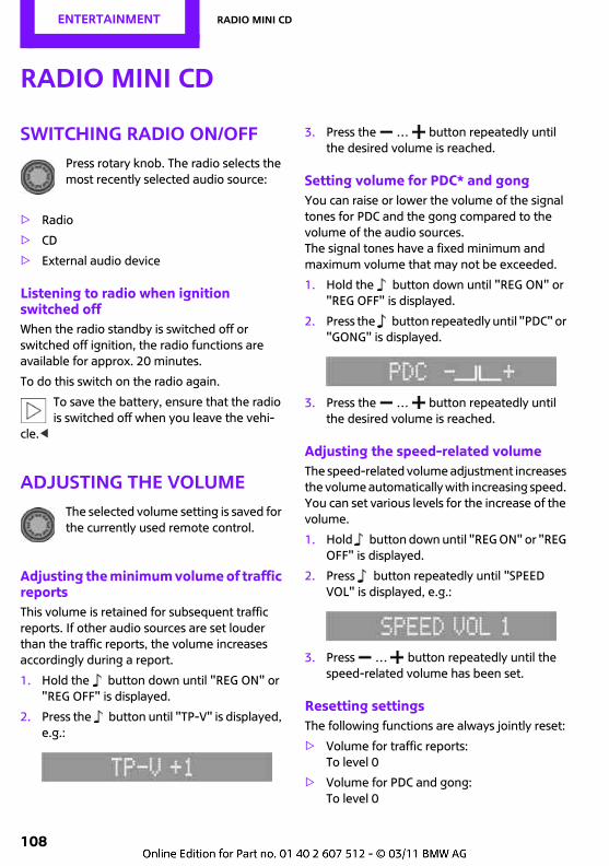
Entertainment Radio MINI CD
108
Radio MINI CD
Switching radio on/offPress rotary knob. The radio selects the most recently selected audio source:
> Radio
> CD
> External audio device
Listening to radio when ignition switched offWhen the radio standby is switched off or switched off ignition, the radio functions are available for approx. 20 minutes.
To do this switch on the radio again.
To save the battery, ensure that the radio is switched off when you leave the vehi-
cle.<
Adjusting the volumeThe selected volume setting is saved for the currently used remote control.
Adjusting the minimum volume of traffic reportsThis volume is retained for subsequent traffic reports. If other audio sources are set louder than the traffic reports, the volume increases accordingly during a report.
1. Hold the button down until "REG ON" or "REG OFF" is displayed.
2. Press the button until "TP-V" is displayed, e.g.:
3. Press the … button repeatedly until the desired volume is reached.
Setting volume for PDC* and gongYou can raise or lower the volume of the signal tones for PDC and the gong compared to the volume of the audio sources.The signal tones have a fixed minimum and maximum volume that may not be exceeded.
1. Hold the button down until "REG ON" or "REG OFF" is displayed.
2. Press the button repeatedly until "PDC" or "GONG" is displayed.
3. Press the … button repeatedly until the desired volume is reached.
Adjusting the speed-related volumeThe speed-related volume adjustment increases the volume automatically with increasing speed. You can set various levels for the increase of the volume.
1. Hold button down until "REG ON" or "REG OFF" is displayed.
2. Press button repeatedly until "SPEED VOL" is displayed, e.g.:
3. Press … button repeatedly until the speed-related volume has been set.
Resetting settingsThe following functions are always jointly reset:
> Volume for traffic reports:To level 0
> Volume for PDC and gong:To level 0
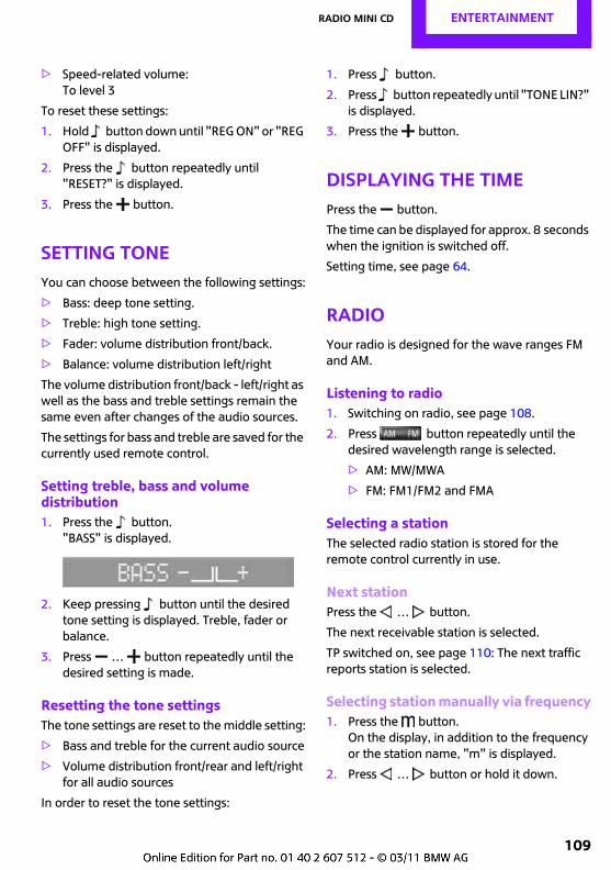
Radio MINI CD Entertainment
109
> Speed-related volume: To level 3
To reset these settings:
1. Hold button down until "REG ON" or "REG OFF" is displayed.
2. Press the button repeatedly until "RESET?" is displayed.
3. Press the button.
Setting toneYou can choose between the following settings:
> Bass: deep tone setting.
> Treble: high tone setting.
> Fader: volume distribution front/back.
> Balance: volume distribution left/right
The volume distribution front/back - left/right as well as the bass and treble settings remain the same even after changes of the audio sources.
The settings for bass and treble are saved for the currently used remote control.
Setting treble, bass and volume distribution1. Press the button.
"BASS" is displayed.
2. Keep pressing button until the desired tone setting is displayed. Treble, fader or balance.
3. Press … button repeatedly until the desired setting is made.
Resetting the tone settingsThe tone settings are reset to the middle setting:
> Bass and treble for the current audio source
> Volume distribution front/rear and left/right for all audio sources
In order to reset the tone settings:
1. Press button.
2. Press button repeatedly until "TONE LIN?" is displayed.
3. Press the button.
Displaying the timePress the button.
The time can be displayed for approx. 8 seconds when the ignition is switched off.
Setting time, see page 64.
RadioYour radio is designed for the wave ranges FM and AM.
Listening to radio1. Switching on radio, see page 108.
2. Press button repeatedly until the desired wavelength range is selected.
> AM: MW/MWA
> FM: FM1/FM2 and FMA
Selecting a stationThe selected radio station is stored for the remote control currently in use.
Next stationPress the … button.
The next receivable station is selected.
TP switched on, see page 110: The next traffic reports station is selected.
Selecting station manually via frequency1. Press the button.
On the display, in addition to the frequency or the station name, "m" is displayed.
2. Press … button or hold it down.
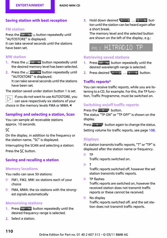
Entertainment Radio MINI CD
110
Saving station with best reception
FM stationPress the button repeatedly until "AUTOSTORE" is displayed.It can take several seconds until the stations have been set.
MW station1. Press the button repeatedly until
the desired memory level has been selected.
2. Press the button repeatedly until "AUTOSTORE" is displayed.It can take several seconds until the stations have been set.
The station saved under station button 1 is set.
If you do not want to use AUTOSTORE, you can save respectively six stations of your
choice in the memory levels FMA or MWA.<
Sampling and selecting a station, ScanYou can sample all receivable stations approx. 10 seconds.
On the display, in addition to the frequency or the station name, "SC" is displayed.
Interrupting the SCAN and selecting a station:
Press the button.
Saving and recalling a station
Memory locationsYou radio can save 30 stations:
> FM1, FM2, MW: six stations each of your choice
> FMA, MWA: the six stations with the strong-est signals automatically
Memorising stations1. Press button repeatedly until the
desired frequency range is selected.
2. Select a station.
3. Hold down desired … but-ton until the station can be heard again after a short break.The memory level and the selected button are shown on the left of the display, e.g.:
Retrieving saved stations1. Press button repeatedly until the
desired wavelength range is selected.
2. Press desired … button.
Traffic reports*You can receive traffic reports, while you are lis-tening to a CD, for example. For this, the TP func-tion, Traffic Programme, must be switched on.
Switching on/off traffic reportsPress the button.The status "TP ON" or "TP OFF" is shown on the display.
Press button again to change the status.
Setting volume for traffic reports, see page 108.
DisplaysIf a station transmits traffic reports, "T" or "TP" is displayed after the station name or frequency.
> TPTraffic reports switched on.
> TTraffic reports switched off, however the set station transmits traffic reports.
> TP flashesTraffic reports are switched on, however the received station does not transmit traffic reports or these cannot be received.
> No displayTraffic reports switched off, and the set sta-tion does not transmit traffic reports.
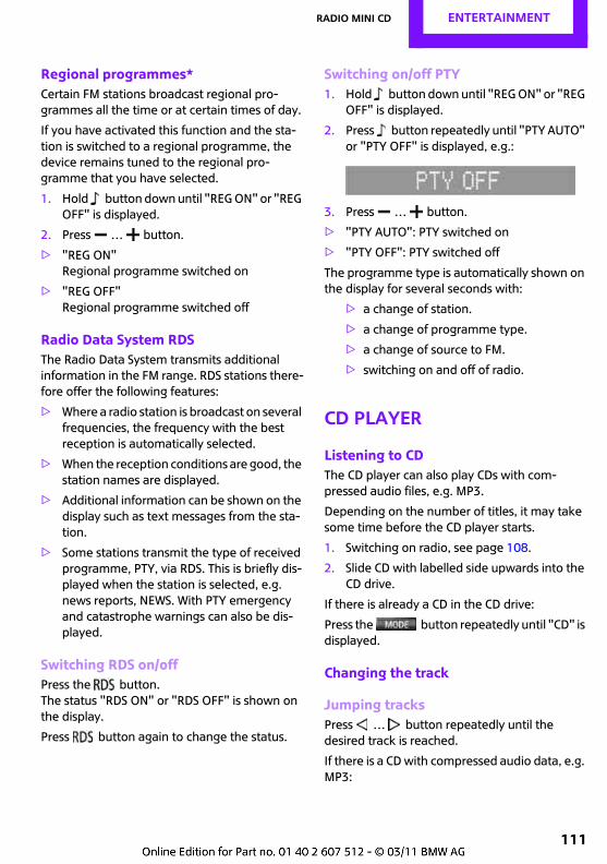
Radio MINI CD Entertainment
111
Regional programmes*Certain FM stations broadcast regional pro-grammes all the time or at certain times of day.
If you have activated this function and the sta-tion is switched to a regional programme, the device remains tuned to the regional pro-gramme that you have selected.
1. Hold button down until "REG ON" or "REG OFF" is displayed.
2. Press … button.
> "REG ON"Regional programme switched on
> "REG OFF"Regional programme switched off
Radio Data System RDSThe Radio Data System transmits additional information in the FM range. RDS stations there-fore offer the following features:
> Where a radio station is broadcast on several frequencies, the frequency with the best reception is automatically selected.
> When the reception conditions are good, the station names are displayed.
> Additional information can be shown on the display such as text messages from the sta-tion.
> Some stations transmit the type of received programme, PTY, via RDS. This is briefly dis-played when the station is selected, e.g. news reports, NEWS. With PTY emergency and catastrophe warnings can also be dis-played.
Switching RDS on/offPress the button.The status "RDS ON" or "RDS OFF" is shown on the display.
Press button again to change the status.
Switching on/off PTY1. Hold button down until "REG ON" or "REG
OFF" is displayed.
2. Press button repeatedly until "PTY AUTO" or "PTY OFF" is displayed, e.g.:
3. Press … button.
> "PTY AUTO": PTY switched on
> "PTY OFF": PTY switched off
The programme type is automatically shown on the display for several seconds with:
> a change of station.
> a change of programme type.
> a change of source to FM.
> switching on and off of radio.
CD player
Listening to CDThe CD player can also play CDs with com-pressed audio files, e.g. MP3.
Depending on the number of titles, it may take some time before the CD player starts.
1. Switching on radio, see page 108.
2. Slide CD with labelled side upwards into the CD drive.
If there is already a CD in the CD drive:
Press the button repeatedly until "CD" is displayed.
Changing the track
Jumping tracksPress … button repeatedly until the desired track is reached.
If there is a CD with compressed audio data, e.g. MP3:
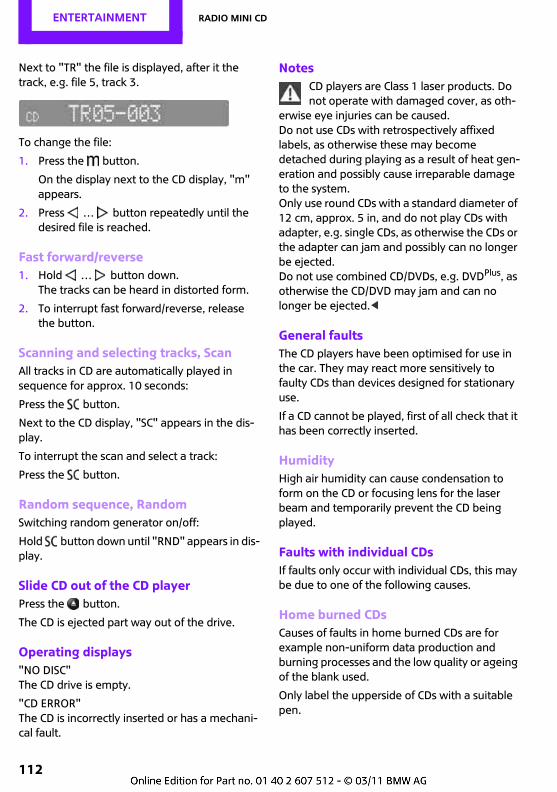
Entertainment Radio MINI CD
112
Next to "TR" the file is displayed, after it the track, e.g. file 5, track 3.
To change the file:
1. Press the button.
On the display next to the CD display, "m" appears.
2. Press … button repeatedly until the desired file is reached.
Fast forward/reverse1. Hold … button down.
The tracks can be heard in distorted form.
2. To interrupt fast forward/reverse, release the button.
Scanning and selecting tracks, ScanAll tracks in CD are automatically played in sequence for approx. 10 seconds:
Press the button.
Next to the CD display, "SC" appears in the dis-play.
To interrupt the scan and select a track:
Press the button.
Random sequence, RandomSwitching random generator on/off:
Hold button down until "RND" appears in dis-play.
Slide CD out of the CD playerPress the button.
The CD is ejected part way out of the drive.
Operating displays"NO DISC"The CD drive is empty.
"CD ERROR"The CD is incorrectly inserted or has a mechani-cal fault.
NotesCD players are Class 1 laser products. Do not operate with damaged cover, as oth-
erwise eye injuries can be caused.Do not use CDs with retrospectively affixed labels, as otherwise these may become detached during playing as a result of heat gen-eration and possibly cause irreparable damage to the system.Only use round CDs with a standard diameter of 12 cm, approx. 5 in, and do not play CDs with adapter, e.g. single CDs, as otherwise the CDs or the adapter can jam and possibly can no longer be ejected.Do not use combined CD/DVDs, e.g. DVDPlus, as otherwise the CD/DVD may jam and can no longer be ejected.<
General faultsThe CD players have been optimised for use in the car. They may react more sensitively to faulty CDs than devices designed for stationary use.
If a CD cannot be played, first of all check that it has been correctly inserted.
HumidityHigh air humidity can cause condensation to form on the CD or focusing lens for the laser beam and temporarily prevent the CD being played.
Faults with individual CDsIf faults only occur with individual CDs, this may be due to one of the following causes.
Home burned CDsCauses of faults in home burned CDs are for example non-uniform data production and burning processes and the low quality or ageing of the blank used.
Only label the upperside of CDs with a suitable pen.
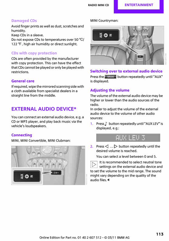
Radio MINI CD Entertainment
113
Damaged CDsAvoid finger prints as well as dust, scratches and humidity.Keep CDs in a sleeve.Do not expose CDs to temperatures over 506/1227, high air humidity or direct sunlight.
CDs with copy protectionCDs are often provided by the manufacturer with copy protection. This can have the effect that CDs cannot be played or only be played with restrictions.
General careIf required, wipe the mirrored scanning side with a cloth available from specialist dealers in a straight line from the middle.
External audio device*You can connect an external audio device, e.g. a CD or MP3 player, and play back music via the vehicle's loudspeakers.
ConnectingMINI, MINI Convertible, MINI Clubman:
MINI Countryman:
Switching over to external audio devicePress the button repeatedly until "AUX" is displayed.
Adjusting the volumeThe volume of the external audio device may be higher or lower than the audio sources of the radio.In order to adjust the volume of the external audio device to the volume of other audio sources:
1. Press button repeatedly until "AUX LEV" is displayed, e.g.:
2. Press … button repeatedly until the desired volume is reached.
You can select a level between 0 and 5.
It is recommended to select neutral tone settings on the external audio device and
to set the volume to the mid range. The sound might vary depending on the quality of the audio files.<
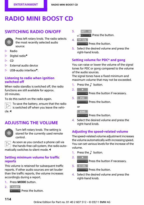
Entertainment Radio MINI Boost CD
114
Radio MINI Boost CD
Switching radio on/offPress left rotary knob. The radio selects the most recently selected audio source:
> Radio
> Digital radio*> CD
> External audio device
> USB-audio interface*.
Listening to radio when ignition switched offWhen radio standby is switched off, the radio functions are still available for approx. 20 minutes.
To do this switch on the radio again.
To save the battery, ensure that the radio is switched off when you leave the vehi-
cle.<
Adjusting the volumeTurn left rotary knob. The setting is stored for the currently used remote control.
As soon as you conduct a phone call via the hands-free call system, the radio auto-
matically switches to silent mode.<
Setting minimum volume for traffic reportsThis volume is retained for subsequent traffic reports. If other audio sources are set louder than the traffic reports, the volume increases accordingly during a report.
1. Press MODE button.
2.Press the button.
3.Press the button.
4. Press the button.
5. Select the desired volume and press the right-hand knob.
Setting volume for PDC* and gongYou can raise or lower the volume of the signal tones for PDC or gong compared to the volume of the audio sources.The signal tones have a fixed minimum and maximum volume that may not be exceeded.
1. Press the button.
2. Press the button if necessary.
3. Press the button.
or
Press the button.
4. Select the desired volume and press the right-hand knob.
Adjusting the speed-related volumeThe speed-related volume adjustment increases the volume automatically with increasing speed. You can set various levels for the increase of the volume.
1. Press the button.
2. Press the button if necessary.
3.Press the button.
4. Select the desired volume and press the right-hand knob.
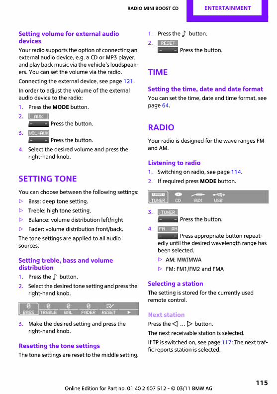
Radio MINI Boost CD Entertainment
115
Setting volume for external audio devicesYour radio supports the option of connecting an external audio device, e.g. a CD or MP3 player, and play back music via the vehicle's loudspeak-ers. You can set the volume via the radio.
Connecting the external device, see page 121.
In order to adjust the volume of the external audio device to the radio:
1. Press the MODE button.
2.Press the button.
3.Press the button.
4. Select the desired volume and press the right-hand knob.
Setting toneYou can choose between the following settings:
> Bass: deep tone setting.
> Treble: high tone setting.
> Balance: volume distribution left/right
> Fader: volume distribution front/back.
The tone settings are applied to all audio sources.
Setting treble, bass and volume distribution1. Press the button.
2. Select the desired tone setting and press the right-hand knob.
3. Make the desired setting and press the right-hand knob.
Resetting the tone settingsThe tone settings are reset to the middle setting.
1. Press the button.
2.Press the button.
Time
Setting the time, date and date formatYou can set the time, date and time format, see page 64.
RadioYour radio is designed for the wave ranges FM and AM.
Listening to radio1. Switching on radio, see page 114.
2. If required press MODE button.
3. Press the button.
4. Press appropriate button repeat-
edly until the desired wavelength range has been selected.
> AM: MW/MWA
> FM: FM1/FM2 and FMA
Selecting a stationThe setting is stored for the currently used remote control.
Next stationPress the … button.
The next receivable station is selected.
If TP is switched on, see page 117: The next traf-fic reports station is selected.
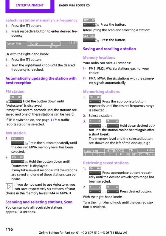
Entertainment Radio MINI Boost CD
116
Selecting station manually via frequency1. Press the button.
2. Press respective button to enter desired fre-quency.
Or with the right-hand knob:
1. Press the button.
2. Turn the right-hand knob until the desired frequency is reached.
Automatically updating the station with best reception
FM station
Hold the button down until "Autostore" is displayed.It may take several seconds until the stations are saved and one of these stations can be heard.
If TP is switched on, see page 117: A traffic reports station is selected.
MW station1.
Press the button repeatedly until the desired MWA memory level has been selected.
2. Hold the button down until
"Autostore" is displayed.It may take several seconds until the stations are saved and one of these stations can be heard.
If you do not want to use Autostore, you can save respectively six stations of your
choice in the memory levels FMA or MWA.<
Scanning and selecting stations, ScanYou can sample all receivable stations approx. 10 seconds.
Press the button.
Interrupting the scan and selecting a station:
Press the button.
Saving and recalling a station
Memory locationsYour radio can save 42 stations:
> FM1, FM2, MW: six stations each of your choice
> FMA, MWA: the six stations with the strong-est signals automatically
Memorising stations1.
Press the appropriate button repeatedly until the desired frequency range is selected.
2. Select a station.
3. … Hold down desired but-
ton until the station can be heard again after a short break.The memory level and the selected button are shown on the left of the display, e.g.:
Retrieving saved stations1.
Press appropriate button repeat-edly until the desired wavelength range has been selected.
2. … Press desired button.
With the right-hand knob:
Turn the right-hand knob until the desired sta-tion is reached.
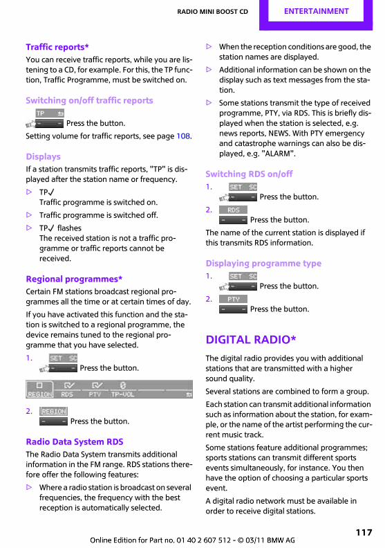
Radio MINI Boost CD Entertainment
117
Traffic reports*You can receive traffic reports, while you are lis-tening to a CD, for example. For this, the TP func-tion, Traffic Programme, must be switched on.
Switching on/off traffic reports
Press the button.
Setting volume for traffic reports, see page 108.
DisplaysIf a station transmits traffic reports, "TP" is dis-played after the station name or frequency.
> TPTraffic programme is switched on.
> Traffic programme is switched off.
> TP flashesThe received station is not a traffic pro-gramme or traffic reports cannot be received.
Regional programmes*Certain FM stations broadcast regional pro-grammes all the time or at certain times of day.
If you have activated this function and the sta-tion is switched to a regional programme, the device remains tuned to the regional pro-gramme that you have selected.
1.Press the button.
2. Press the button.
Radio Data System RDSThe Radio Data System transmits additional information in the FM range. RDS stations there-fore offer the following features:
> Where a radio station is broadcast on several frequencies, the frequency with the best reception is automatically selected.
> When the reception conditions are good, the station names are displayed.
> Additional information can be shown on the display such as text messages from the sta-tion.
> Some stations transmit the type of received programme, PTY, via RDS. This is briefly dis-played when the station is selected, e.g. news reports, NEWS. With PTY emergency and catastrophe warnings can also be dis-played, e.g. "ALARM".
Switching RDS on/off1.
Press the button.
2.Press the button.
The name of the current station is displayed if this transmits RDS information.
Displaying programme type1.
Press the button.
2.Press the button.
Digital radio*The digital radio provides you with additional stations that are transmitted with a higher sound quality.
Several stations are combined to form a group.
Each station can transmit additional information such as information about the station, for exam-ple, or the name of the artist performing the cur-rent music track.
Some stations feature additional programmes; sports stations can transmit different sports events simultaneously, for instance. You then have the option of choosing a particular sports event.
A digital radio network must be available in order to receive digital stations.
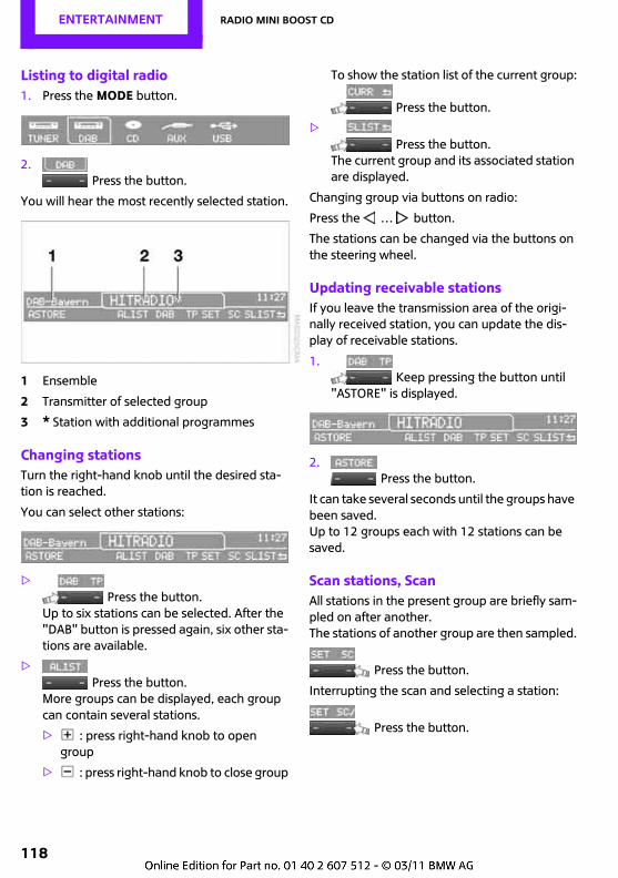
Entertainment Radio MINI Boost CD
118
Listing to digital radio1. Press the MODE button.
2.Press the button.
You will hear the most recently selected station.
1 Ensemble
2 Transmitter of selected group
3 * Station with additional programmes
Changing stationsTurn the right-hand knob until the desired sta-tion is reached.
You can select other stations:
>Press the button.
Up to six stations can be selected. After the "DAB" button is pressed again, six other sta-tions are available.
>Press the button.
More groups can be displayed, each group can contain several stations.
> : press right-hand knob to open group
> : press right-hand knob to close group
To show the station list of the current group:
Press the button.
>Press the button.
The current group and its associated station are displayed.
Changing group via buttons on radio:
Press the … button.
The stations can be changed via the buttons on the steering wheel.
Updating receivable stationsIf you leave the transmission area of the origi-nally received station, you can update the dis-play of receivable stations.
1. Keep pressing the button until
"ASTORE" is displayed.
2.Press the button.
It can take several seconds until the groups have been saved.Up to 12 groups each with 12 stations can be saved.
Scan stations, ScanAll stations in the present group are briefly sam-pled on after another.The stations of another group are then sampled.
Press the button.
Interrupting the scan and selecting a station:
Press the button.
Radio MINI Boost CD Entertainment
119
Memorising stationsYou can save 12 stations:
1. Select station.
2. … Hold down desired but-
ton until the station can be heard again after a short break.
Selecting frequency rangeSome digital stations are transmitted digitally, other interregionally.You can obtain more detailed information on the frequency ranges from your Service.
1.Press the button.
2. Selecting desired frequency range:
> "BAND 3" for transregional stations
> "L-BAND" for regional stations
3. Press the right-hand knob.
Displaying additional informationDepending on a station's offer, additional infor-mation can be displayed, such as information about the station or the name of the artist for the current music track.
1.Press the button.
2.Press the button.
Hearing additional programmesThis symbol is shown if a selected station offers additional programmes. Sports stations, for example, may broadcast different sports events at the same time.
1.Press the button.
2. Select station.
3. Select the additional programme.
If the programme is over, the radio switches to the selected station.
CD player
Starting CD playerIt can take a while before the CD player starts.
1. Switching on radio, see page 114.
2. Slide CD with labelled side upwards into the CD drive.
If there is already a CD in the CD drive:
1. If required switch on radio
2. Press the MODE button.
3.Press the button.
Changing the track
Jumping tracksPress … button repeatedly until the desired track is reached.
With the right-hand knob:Turn right-hand knob until the desired track is reached.
Fast forward/reverse1. Hold … button down.
The tracks can be heard in distorted form.
2. To interrupt fast forward/reverse, release the button.
Random sequence, Random
Press the button.
To quit the random generator:
Press the button.
Scanning and selecting tracks, Scan
Press the button.
Entertainment Radio MINI Boost CD
120
To interrupt the scan and select a track:
Press the button.
Selecting MP3 tracksThe CD player can also play CDs with com-pressed audio files, e.g. MP3 and WMA.
Selecting a track1.
Press the button.
2. Select the desired file and press the right-hand knob.
> : press right-hand knob to open file
> : press right-hand knob to close file
3. If required select other sub-files and press right-hand knob.
4. Select the desired track and press the right-hand knob.
You can scroll through the file during replay.
To change to the current track:
Press the button.
Track displayYou can access any information available on the current track:
1. Press button.
2. Press button.
Slide CD out of the CD playerPress the button.
The CD is ejected part way out of the drive.
Operating displays> "Insert CD"
The CD drive is empty.
> "Error CD"The CD cannot be read or is defective.
> "Temp. CD"Operating temperature too high.
NotesCD players are Class 1 laser products. Do not operate with damaged cover or
severe eye injuries can result.Do not use CDs with retrospectively affixed labels, as otherwise these may become detached during playing as a result of heat gen-eration and possibly cause irreparable damage to the system.Only use round CDs with a standard diameter of 12 cm, approx. 5 in, and do not play CDs with adapter, e.g. single CDs, as otherwise the CDs or the adapter can jam and possibly can no longer be ejected.Do not use combined CD/DVDs, e.g. DVDPlus, as otherwise the CD/DVD may jam and can no longer be ejected.<
General faultsThe CD players have been optimised for use in the car. They may react more sensitively to faulty CDs than devices designed for stationary use.
If a CD cannot be played, first of all check that it has been correctly inserted.
HumidityHigh air humidity can cause condensation to form on the CD or focusing lens for the laser beam and temporarily prevent the CD being played.
Faults with individual CDsIf faults only occur with individual CDs, this may be due to one of the following causes.
Home burned CDsCauses of faults in home burned CDs are for example non-uniform data production and burning processes and the low quality or ageing of the blank used.
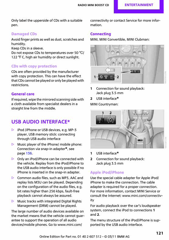
Radio MINI Boost CD Entertainment
121
Only label the upperside of CDs with a suitable pen.
Damaged CDsAvoid finger prints as well as dust, scratches and humidity.Keep CDs in a sleeve.Do not expose CDs to temperatures over 506/1227C, high air humidity or direct sunlight.
CDs with copy protectionCDs are often provided by the manufacturer with copy protection. This can have the effect that CDs cannot be played or only be played with restrictions.
General careIf required, wipe the mirrored scanning side with a cloth available from specialist dealers in a straight line from the middle.
USB audio interface*> iPod /iPhone or USB devices, e.g. MP-3
player, USB memory stick: connecting through USB audio interface
> Music player of the iPhone/ mobile phone: Connection via snap-in adapter*, see page 136.
> Only an iPod/iPhone can be connected with the vehicle. Replay from the iPod/iPhone to the USB audio interface is only possible if no iPhone is inserted in the snap-in adapter.
> Common audio files, such as MP3, AAC and replay lists M3U can be played. Depending on the configuration of the audio files, e.g. bit rates higher than 256 kbps, fault-free playback cannot always be assured.
> Music tracks with integrated Digital Rights Management (DRM) cannot be played.
The large number of audio devices available on the market means that the vehicle cannot guar-antee to support the operation of all audio devices/mobile phones. Go to www.mini.com/
connectivity or contact Service for more infor-mation.
ConnectingMINI, MINI Convertible, MINI Clubman:
1 Connection for sound playback:Jack plug 3.5 mm
2 USB interface*MINI Countryman:
1 USB interface*2 Connection for sound playback:
Jack plug 3.5 mm
Apple iPod/iPhoneUse the special cable adapter for Apple iPod/iPhone to make the connection. The cable adapter is required for a proper connection.For more information, contact MINI Service or consult the Internet: www.mini.com/connectiv-ity
For audio playback over the car's loudspeaker system, connect the iPod to connections 1 and 2.
The menu structure of the iPod/iPhone is sup-ported by the USB audio interface.
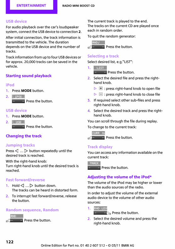
Entertainment Radio MINI Boost CD
122
USB deviceFor audio playback over the car's loudspeaker system, connect the USB device to connection 2.
After initial connection, the track information is transmitted to the vehicle. The duration depends on the USB device and the number of tracks.
Track information from up to four USB devices or for approx. 20,000 tracks can be saved in the vehicle.
Starting sound playback
iPod1. Press MODE button.
2.Press the button.
USB device1. Press MODE button.
2.Press the button.
Changing the track
Jumping tracksPress … button repeatedly until the desired track is reached.
With the right-hand knob:Turn right-hand knob until the desired track is reached.
Fast forward/reverse1. Hold … button down.
The tracks can be heard in distorted form.
2. To interrupt fast forward/reverse, release the button.
Random sequence, Random
Press the button.
The current track is played to the end. The tracks on the current CD are played once each in random order.
To quit the random generator:
Press the button.
Selecting a trackSelect desired list, e.g."LIST":
1.Press the button.
2. Select the desired file and press the right-hand knob.
> : press right-hand knob to open file
> : press right-hand knob to close file
3. If required select other sub-files and press right-hand knob.
4. Select the desired track and press the right-hand knob.
You can scroll through the file during replay.
To change to the current track:
Press the button.
Track displayYou can access any information available on the current track:
Press the button.
Adjusting the volume of the iPod*The volume of the iPod may be higher or lower than the audio sources of the radio.
In order to adjust the volume of the external audio device to the volume of other audio sources:
1.Press the button.
2. Select the desired volume and press the right-hand knob.
Radio MINI Boost CD Entertainment
123
Notes> The USB/audio interface supplies the con-
nected audio devices with current if the audio device supports this. For this reason, do not connect the audio device to the socket in the vehicle during operation.
> Do not expose audio devices to extreme ambient conditions, e.g. very high tempera-tures, see the operating instructions for the audio device.
> Do not connect any devices such as fans or lamps to the USB audio interface.
> Do not connect up USB hard drives.

Connect Me.
OVERVIEW
CONTROLS
DRIVING HINTS
Entertainment
MOBILITY
REFERENCE
COMMUNICATION
COMMUNICATION Telephone
126
Telephone
Overview
PrincipleMobile phones or other external devices such as audio players can be connected to the vehicle over Bluetooth.
Your MINI is equipped with a mobile phone preparation. As soon as you have performed a one-off pairing procedure in the vehicle with a suitable mobile phone, you will be able to oper-ate it via the radio, using the buttons* on the steering wheel and by voice control*.
Some functions might need to be enabled by your mobile phone provider.
Only make inputs when it is safe to do so without risk to yourself or other road
users. Do not hold the mobile phone in your hand while driving; use the hands-free unit instead. You could otherwise be distracted and put both the occupants of your vehicle and other road users at risk.<
Snap-in adapter*The snap-in adapter, see page 136:
> Provides a holder for the mobile phone.
> Charges the battery.
> Establishes a connection to the vehicle's external antenna.
This ensures better network reception and consistent sound quality.
Do not use the keypad on the mobile phone to operate the mobile phone connected to the vehicle as this can lead to malfunctions.
Suitable mobile phonesFor detailed information about which mobile phones and external devices with Bluetooth interface are supported by the mobile phone preparation, go to www.mini.com/connectivity.
*
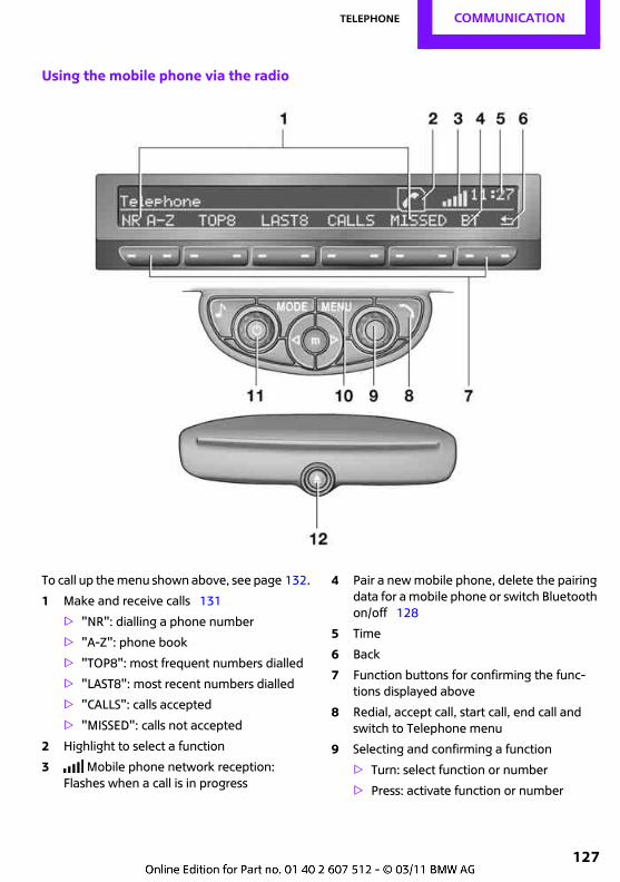
Telephone COMMUNICATION
127
Using the mobile phone via the radio
To call up the menu shown above, see page 132.
1 Make and receive calls 131
> "NR": dialling a phone number
> "A-Z": phone book
> "TOP8": most frequent numbers dialled
> "LAST8": most recent numbers dialled
> "CALLS": calls accepted
> "MISSED": calls not accepted
2 Highlight to select a function
3 Mobile phone network reception:Flashes when a call is in progress
4 Pair a new mobile phone, delete the pairing data for a mobile phone or switch Bluetooth on/off 128
5 Time
6 Back
7 Function buttons for confirming the func-tions displayed above
8 Redial, accept call, start call, end call and switch to Telephone menu
9 Selecting and confirming a function
> Turn: select function or number
> Press: activate function or number
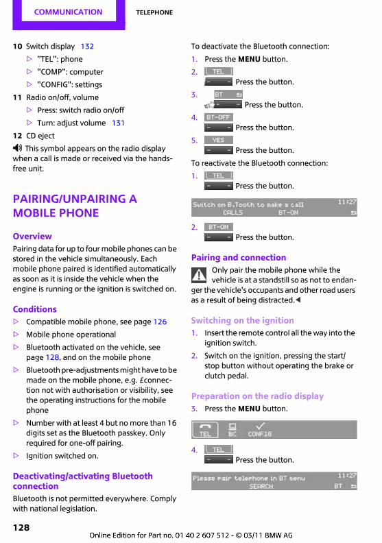
COMMUNICATION Telephone
128
10 Switch display 132
> "TEL": phone
> "COMP": computer
> "CONFIG": settings
11 Radio on/off, volume
> Press: switch radio on/off
> Turn: adjust volume 131
12 CD eject
This symbol appears on the radio display when a call is made or received via the hands-free unit.
Pairing/Unpairing a mobile phone
OverviewPairing data for up to four mobile phones can be stored in the vehicle simultaneously. Each mobile phone paired is identified automatically as soon as it is inside the vehicle when the engine is running or the ignition is switched on.
Conditions> Compatible mobile phone, see page 126
> Mobile phone operational
> Bluetooth activated on the vehicle, see page 128, and on the mobile phone
> Bluetooth pre-adjustments might have to be made on the mobile phone, e.g. £connec-tion not with authorisation or visibility, see the operating instructions for the mobile phone
> Number with at least 4 but no more than 16 digits set as the Bluetooth passkey. Only required for one-off pairing.
> Ignition switched on.
Deactivating/activating Bluetooth connectionBluetooth is not permitted everywhere. Comply with national legislation.
To deactivate the Bluetooth connection:
1. Press the MENU button.
2. Press the button.
3. Press the button.
4. Press the button.
5. Press the button.
To reactivate the Bluetooth connection:
1. Press the button.
2. Press the button.
Pairing and connectionOnly pair the mobile phone while the vehicle is at a standstill so as not to endan-
ger the vehicle's occupants and other road users as a result of being distracted.<
Switching on the ignition1. Insert the remote control all the way into the
ignition switch.
2. Switch on the ignition, pressing the start/stop button without operating the brake or clutch pedal.
Preparation on the radio display3. Press the MENU button.
4. Press the button.
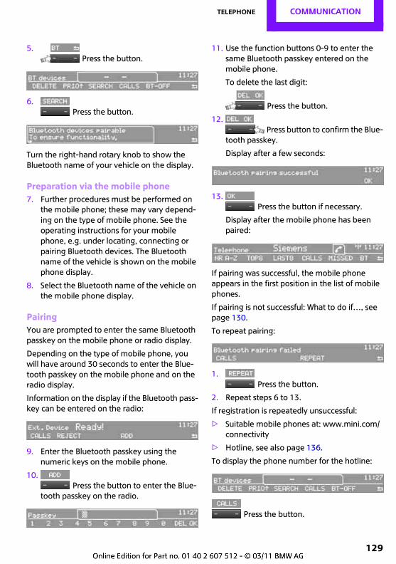
Telephone COMMUNICATION
129
5. Press the button.
6. Press the button.
Turn the right-hand rotary knob to show the Bluetooth name of your vehicle on the display.
Preparation via the mobile phone7. Further procedures must be performed on
the mobile phone; these may vary depend-ing on the type of mobile phone. See the operating instructions for your mobile phone, e.g. under locating, connecting or pairing Bluetooth devices. The Bluetooth name of the vehicle is shown on the mobile phone display.
8. Select the Bluetooth name of the vehicle on the mobile phone display.
PairingYou are prompted to enter the same Bluetooth passkey on the mobile phone or radio display.
Depending on the type of mobile phone, you will have around 30 seconds to enter the Blue-tooth passkey on the mobile phone and on the radio display.
Information on the display if the Bluetooth pass-key can be entered on the radio::
9. Enter the Bluetooth passkey using the numeric keys on the mobile phone.
10. Press the button to enter the Blue-
tooth passkey on the radio.
11. Use the function buttons 0-9 to enter the same Bluetooth passkey entered on the mobile phone.
To delete the last digit:
Press the button.
12. Press button to confirm the Blue-
tooth passkey.
Display after a few seconds:
13. Press the button if necessary.
Display after the mobile phone has been paired:
If pairing was successful, the mobile phone appears in the first position in the list of mobile phones.
If pairing is not successful: What to do if…, see page 130.
To repeat pairing:
1. Press the button.
2. Repeat steps 6 to 13.
If registration is repeatedly unsuccessful:
> Suitable mobile phones at: www.mini.com/connectivity
> Hotline, see also page 136.
To display the phone number for the hotline:
Press the button.
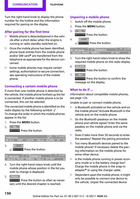
COMMUNICATION Telephone
130
Turn the right-hand knob to display the phone number for the hotline and the information required for pairing on the display.
After pairing for the first time> Mobile phone is detected/paired in the vehi-
cle after a short delay when the engine is running or radio standby switched on.
> Once the mobile phone has been identified, phone book entries from the mobile phone and/or SIM card* are transferred from the telephone as appropriate for the device con-cerned.
> Some mobile phones may require certain settings, authorisation or secure connection, see operating instructions of the mobile phone.
Connecting a certain mobile phoneIf more than one mobile phone is detected by the vehicle, the mobile phone furthest up the list is connected. If another mobile phone is to be connected, this can be selected.
The connected mobile phone is identified on the radio display by the following symbol: To change the order in which the mobile phones appear in the list:
1. Press the MENU button.
2. Press the button.
3. Press the button.
4. Turn the right-hand rotary knob until the mobile phone whose position in the list you wish to change is displayed.
5. Press the button as often as neces-
sary until the desired chapter is reached.
Unpairing a mobile phone1. Switch off the mobile phone.
2. Press the MENU button.
3. Press the button.
4. Press the button.
5. Turn the right-hand rotary knob to show the required mobile phone on the radio display.
6. Press the button.
7. Press the button to confirm the
message on the display.
What to do if ...Information about compatible mobile phones, see page 126.
Unable to pair or connect mobile phone.
> Is Bluetooth activated on the vehicle and on the mobile phone? Activate Bluetooth in the vehicle and on the mobile phone.
> Do the Bluetooth passkeys on the mobile phone and vehicle agree? Enter the same passkey on the mobile phone and via the radio.
> Does it take more than 30 seconds to enter the passkey? Repeat the pairing procedure.
> Too many Bluetooth devices paired to the mobile phone? If necessary delete the pair-ing information on the mobile phone for some other device.
> Is the mobile phone running in power econ-omy mode or is the battery charge low? Charge the mobile phone in the snap-in adapter* or using the charger cable.
> Dependent upon the mobile phone, it might only be possible to connect one device to the vehicle. Unpair the connected device
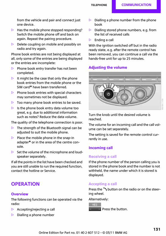
Telephone COMMUNICATION
131
from the vehicle and pair and connect just one device.
> Has the mobile phone stopped responding? Switch the mobile phone off and back on again. Repeat the pairing procedure.
> Delete coupling on mobile and possibly on radio and try again.
Phone book entries are not being displayed at all, only some of the entries are being displayed or the entries are incomplete:
> Phone book entry transfer has not been completed.
> It might be the case that only the phone book entries from the mobile phone or the SIM card* have been transferred.
> Phone book entries with special characters may sometimes not be displayed.
> Too many phone book entries to be saved.
> Is the phone book entry data volume too great, e.g. due to additional information such as notes? Reduce the data volume.
The quality of the telephone connection is poor.
> The strength of the Bluetooth signal can be adjusted to suit the mobile phone.
> Place the mobile phone in the snap-in adapter* or in the area of the centre con-sole.
> Set the volume of the microphone and loud-speaker separately.
If all the points in the list have been checked and you are still unable to run the required function, contact the hotline or Service.
Operation
OverviewThe following functions can be operated via the radio:
> Accepting/rejecting a call
> Dialling a phone number
> Dialling a phone number from the phone book
> Dialling stored phone numbers, e.g. from the list of received calls
> Ending a call
With the ignition switched off but in the radio ready state, e.g. after the remote control has been removed, you can continue a call via the hands-free unit for up to 25 minutes.
Adjusting the volume
Turn the knob until the desired volume is reached.
The volume for an incoming call and the call vol-ume can be set separately.
The setting is saved for the remote control cur-rently in use.
Incoming call
Receiving a callIf the phone number of the person calling you is stored in the phone book and the number is not withheld, the name under which it is stored is displayed.
Accepting a callPress the button on the radio or on the steer-ing wheel.
Alternatively:
Press the button.
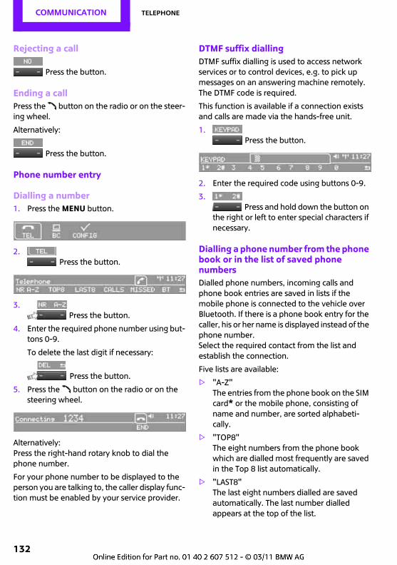
COMMUNICATION Telephone
132
Rejecting a call
Press the button.
Ending a callPress the button on the radio or on the steer-ing wheel.
Alternatively:
Press the button.
Phone number entry
Dialling a number1. Press the MENU button.
2. Press the button.
3. Press the button.
4. Enter the required phone number using but-tons 0-9.
To delete the last digit if necessary:
Press the button.
5. Press the button on the radio or on the steering wheel.
Alternatively:Press the right-hand rotary knob to dial the phone number.
For your phone number to be displayed to the person you are talking to, the caller display func-tion must be enabled by your service provider.
DTMF suffix diallingDTMF suffix dialling is used to access network services or to control devices, e.g. to pick up messages on an answering machine remotely. The DTMF code is required.
This function is available if a connection exists and calls are made via the hands-free unit.
1. Press the button.
2. Enter the required code using buttons 0-9.
3. Press and hold down the button on
the right or left to enter special characters if necessary.
Dialling a phone number from the phone book or in the list of saved phone numbersDialled phone numbers, incoming calls and phone book entries are saved in lists if the mobile phone is connected to the vehicle over Bluetooth. If there is a phone book entry for the caller, his or her name is displayed instead of the phone number.Select the required contact from the list and establish the connection.
Five lists are available:
> "A-Z"The entries from the phone book on the SIM card* or the mobile phone, consisting of name and number, are sorted alphabeti-cally.
> "TOP8" The eight numbers from the phone book which are dialled most frequently are saved in the Top 8 list automatically.
> "LAST8"The last eight numbers dialled are saved automatically. The last number dialled appears at the top of the list.
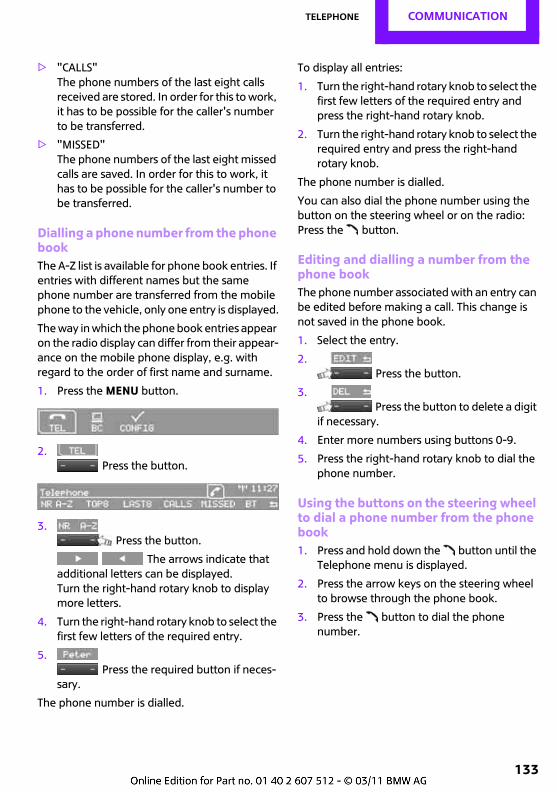
Telephone COMMUNICATION
133
> "CALLS"The phone numbers of the last eight calls received are stored. In order for this to work, it has to be possible for the caller's number to be transferred.
> "MISSED"The phone numbers of the last eight missed calls are saved. In order for this to work, it has to be possible for the caller's number to be transferred.
Dialling a phone number from the phone bookThe A-Z list is available for phone book entries. If entries with different names but the same phone number are transferred from the mobile phone to the vehicle, only one entry is displayed.
The way in which the phone book entries appear on the radio display can differ from their appear-ance on the mobile phone display, e.g. with regard to the order of first name and surname.
1. Press the MENU button.
2. Press the button.
3. Press the button.
The arrows indicate that additional letters can be displayed. Turn the right-hand rotary knob to display more letters.
4. Turn the right-hand rotary knob to select the first few letters of the required entry.
5. Press the required button if neces-
sary.
The phone number is dialled.
To display all entries:
1. Turn the right-hand rotary knob to select the first few letters of the required entry and press the right-hand rotary knob.
2. Turn the right-hand rotary knob to select the required entry and press the right-hand rotary knob.
The phone number is dialled.
You can also dial the phone number using the button on the steering wheel or on the radio:Press the button.
Editing and dialling a number from the phone bookThe phone number associated with an entry can be edited before making a call. This change is not saved in the phone book.
1. Select the entry.
2. Press the button.
3. Press the button to delete a digit
if necessary.
4. Enter more numbers using buttons 0-9.
5. Press the right-hand rotary knob to dial the phone number.
Using the buttons on the steering wheel to dial a phone number from the phone book1. Press and hold down the button until the
Telephone menu is displayed.
2. Press the arrow keys on the steering wheel to browse through the phone book.
3. Press the button to dial the phone number.
COMMUNICATION Telephone
134
Dialling phone numbers saved in a listTo select an entry and establish a connection:
1. Press the MENU button.
2. Press the button.
3. Press the required button to select
one of the four lists.
4. Turn the right-hand rotary knob to select an entry and press the same knob to dial the phone number.
Deleting individual entries1. Select the desired entry from the list.
2. Press the button.
Displaying call durationTo display the duration during a call:
Press the button.
Hands-free unit
GeneralCalls made and received using the hands-free unit can be switched over to the mobile phone and vice versa.
From the mobile phone to the hands-free unitCalls started outside the Bluetooth range of the vehicle can be switched over to the hands-free unit if the ignition is switched on.
Depending on the type of mobile phone, switch-over to hands-free mode may take place auto-matically.
If switchover is not automatic, follow the instruc-tions on the mobile phone display, see also the operating instructions for the mobile phone.
From the hands-free unit to the mobile phoneIn some cases calls made and received using the hands-free unit can be switched over to the mobile phone, dependent upon the model.
Follow the instructions on the mobile phone dis-play, see also the operating instructions for the mobile phone.
Operation by voice control*
Principle> You can use the mobile phone without tak-
ing your hands off the steering wheel.
> In many cases, entries are made by saying commands or asking questions.
> {...} identifies commands for the voice con-trol system.
> {{...}} identifies replies by the voice control system.
Speaking commands
Activating voice input1. Press and release the button on the
steering wheel.
An acoustic signal indicates that you can say commands. Display on the radio:
2. Issue the command.
Completing voice inputPress and release the button on the steering wheel or
{Cancel}.
Telephone COMMUNICATION
135
Possible commands
Having possible commands read aloudPress the button on the steering wheel.
Possible commands are read aloud.
You can say each digit individually or say the entire number as a block to speed up the input process.
Using alternative commandsThere are often several different commands available for performing the same function, e.g.:
An example: dialling a phone number1. Press and release the button on the
steering wheel.
2. {Dial number}
3. The system says: {{Please say the number}}
4. E.g. {123 456 7890}
5. The system says: {{123 456 7890. Con-tinue?}}
6. {Dial}System says: {{Dialling number}}
Making a call
Dialling a phone number
The connection with the desired subscriber is established.
Correcting a phone numberA block of digits can be deleted once the system has repeated the digits concerned.
The command can be repeated as often as you wish.
Deleting a phone number
All previously entered digits are deleted.
Redial
Voice-activated phone book*Depending on the equipment available in your vehicle, it may be necessary to create a separate voice-activated phone book.
The names and numbers in the voice phone book are independent of the mobile phone's memory or SIM card. Therefore, phone numbers saved in the mobile phone or on the SIM card cannot be called up using voice input or saved to these locations using voice input.
Saving an entry
Deleting an entry
Deleting all entries
{Help}.
{Dial name} or {Name}.
1. {Dial number}.
2. Say the phone number.
3. {Dial}.
{Correct number}.
{Delete}.
{Redial}.
1. {Save name}.
2. Say the name. Do not speak for more than approx. 2 seconds.
3. When prompted by the system, say the phone number.
4. {Save}.
1. {Delete name}.
2. When asked to do so, say the name.
3. Confirm request with {Yes}.
1. {Delete phonebook}.The dialogue for deleting the phone book is called up.
2. Confirm request with {Yes}.
3. Confirm the repeated query with {Yes}.
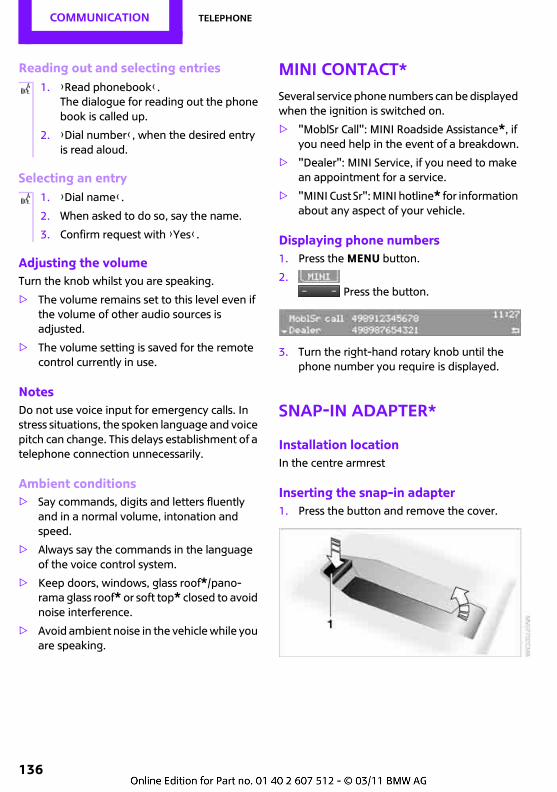
COMMUNICATION Telephone
136
Reading out and selecting entries
Selecting an entry
Adjusting the volumeTurn the knob whilst you are speaking.
> The volume remains set to this level even if the volume of other audio sources is adjusted.
> The volume setting is saved for the remote control currently in use.
NotesDo not use voice input for emergency calls. In stress situations, the spoken language and voice pitch can change. This delays establishment of a telephone connection unnecessarily.
Ambient conditions> Say commands, digits and letters fluently
and in a normal volume, intonation and speed.
> Always say the commands in the language of the voice control system.
> Keep doors, windows, glass roof*/pano-rama glass roof* or soft top* closed to avoid noise interference.
> Avoid ambient noise in the vehicle while you are speaking.
MINI Contact*Several service phone numbers can be displayed when the ignition is switched on.
> "MoblSr Call": MINI Roadside Assistance*, if you need help in the event of a breakdown.
> "Dealer": MINI Service, if you need to make an appointment for a service.
> "MINI Cust Sr": MINI hotline* for information about any aspect of your vehicle.
Displaying phone numbers1. Press the MENU button.
2. Press the button.
3. Turn the right-hand rotary knob until the phone number you require is displayed.
Snap-in adapter*
Installation locationIn the centre armrest
Inserting the snap-in adapter1. Press the button and remove the cover.
1. {Read phonebook}.The dialogue for reading out the phone book is called up.
2. {Dial number}, when the desired entry is read aloud.
1. {Dial name}.
2. When asked to do so, say the name.
3. Confirm request with {Yes}.
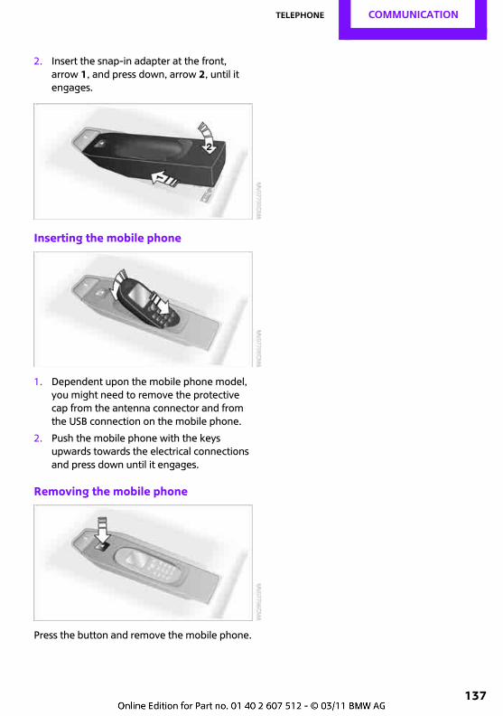
Telephone COMMUNICATION
137
2. Insert the snap-in adapter at the front, arrow 1, and press down, arrow 2, until it engages.
Inserting the mobile phone
1. Dependent upon the mobile phone model, you might need to remove the protective cap from the antenna connector and from the USB connection on the mobile phone.
2. Push the mobile phone with the keys upwards towards the electrical connections and press down until it engages.
Removing the mobile phone
Press the button and remove the mobile phone.
Move Me.
OVERVIEW
CONTROLS
DRIVING HINTS
Entertainment
COMMUNICATION
REFERENCE
MOBILITY
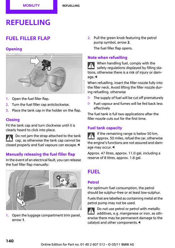
MOBILITY Refuelling
140
Refuelling
Fuel filler flap
Opening
1. Open the fuel filler flap.
2. Turn the fuel filler cap anticlockwise.
3. Place the tank cap in the holder on the flap.
ClosingFit the tank cap and turn clockwise until it is clearly heard to click into place.
Do not jam the strap attached to the tank cap, as otherwise the tank cap cannot be
closed properly and fuel vapours can escape.<
Manually releasing the fuel filler flapIn the event of an electrical fault, you can release the fuel filler flap manually:
1. Open the luggage compartment trim panel, arrow 1.
2. Pull the green knob featuring the petrol pump symbol, arrow 2.
The fuel filler flap opens.
Note when refuellingWhen handling fuel, comply with the safety regulations displayed by filling sta-
tions, otherwise there is a risk of injury or dam-age.<
When refuelling, insert the filler nozzle fully into the filler neck. Avoid lifting the filler nozzle dur-ing refuelling, otherwise
> The supply of fuel will be cut off prematurely
> Fuel vapour and fumes will be fed back less effectively
The fuel tank is full two applications after the filler nozzle cuts out for the first time.
Fuel tank capacityIf the remaining range is below 50 km, approx. 30 miles, refuel the car, otherwise
the engine's functions are not assured and dam-age may occur.<
Approx. 47 litres, approx. 11.0 gal, including a reserve of 8 litres, approx. 1.8 gal.
Fuel
PetrolFor optimum fuel consumption, the petrol should be sulphur-free or at least low-sulphur.
Fuels that are labelled as containing metal at the petrol pump may not be used.
Do not use petrol or petrol with metallic additives, e.g. manganese or iron, as oth-
erwise there may be permanent damage to the catalyst and other components.<
Refuelling MOBILITY
141
The vehicle can be refuelled with fuel containing a maximum of 10% ethanol, i.e. E10.
Do not use E85, i.e. fuel that contains 85% ethanol, or FlexFuel. Otherwise the engine
and the fuel supply system will be damaged.<
Petrol qualityThe engine is knocking adjusted. Therefore dif-ferent petrol qualities can be used.
The manufacturer of your MINI recommends:
> Premium-grade fuel: 95 RON.
> Cooper S 98 RON
Fuel grades with 91 RON or higher are permissi-ble.
Do not fill the tank with fuel under 91 RON, as otherwise the engine and the
fuel supply system will be damaged.<
DieselDo not use rapeseed methyl ester RME, biodiesel or petrol. If the wrong type of
fuel has been added, do not start the engine, otherwise you risk causing damage to it.<
The filler neck is designed to accommodate the filler nozzles of diesel fuel pumps.
Contact MINI Service if the wrong type of fuel has been added.
Diesel qualityThe engine of your MINI is designed to run on:Diesel oil to DIN EN 590 standard.
Winter-grade diesel oilTo ensure that the diesel engine operates relia-bly during the cold season of the year, it must be run on winter-grade diesel oil, which garages usually sell during the period in question. Fuel filter heating is installed as standard equipment to prevent the fuel solidifying during operation.
Do not incorporate any additives, includ-ing petrol, as these could cause damage to
the engine.<
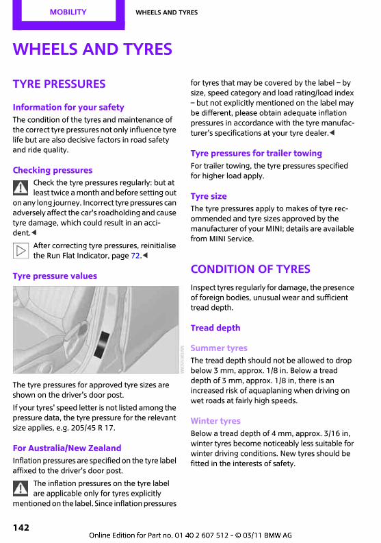
MOBILITY Wheels and tyres
142
Wheels and tyres
Tyre pressures
Information for your safetyThe condition of the tyres and maintenance of the correct tyre pressures not only influence tyre life but are also decisive factors in road safety and ride quality.
Checking pressuresCheck the tyre pressures regularly: but at least twice a month and before setting out
on any long journey. Incorrect tyre pressures can adversely affect the car's roadholding and cause tyre damage, which could result in an acci-dent.<
After correcting tyre pressures, reinitialise the Run Flat Indicator, page 72.<
Tyre pressure values
The tyre pressures for approved tyre sizes are shown on the driver's door post.
If your tyres' speed letter is not listed among the pressure data, the tyre pressure for the relevant size applies, e.g. 205/45 R 17.
For Australia/New ZealandInflation pressures are specified on the tyre label affixed to the driver's door post.
The inflation pressures on the tyre label are applicable only for tyres explicitly
mentioned on the label. Since inflation pressures
for tyres that may be covered by the label – by size, speed category and load rating/load index – but not explicitly mentioned on the label may be different, please obtain adequate inflation pressures in accordance with the tyre manufac-turer's specifications at your tyre dealer.<
Tyre pressures for trailer towingFor trailer towing, the tyre pressures specified for higher load apply.
Tyre sizeThe tyre pressures apply to makes of tyre rec-ommended and tyre sizes approved by the manufacturer of your MINI; details are available from MINI Service.
Condition of tyresInspect tyres regularly for damage, the presence of foreign bodies, unusual wear and sufficient tread depth.
Tread depth
Summer tyresThe tread depth should not be allowed to drop below 3 mm, approx. 1/8 in. Below a tread depth of 3 mm, approx. 1/8 in, there is an increased risk of aquaplaning when driving on wet roads at fairly high speeds.
Winter tyresBelow a tread depth of 4 mm, approx. 3/16 in, winter tyres become noticeably less suitable for winter driving conditions. New tyres should be fitted in the interests of safety.
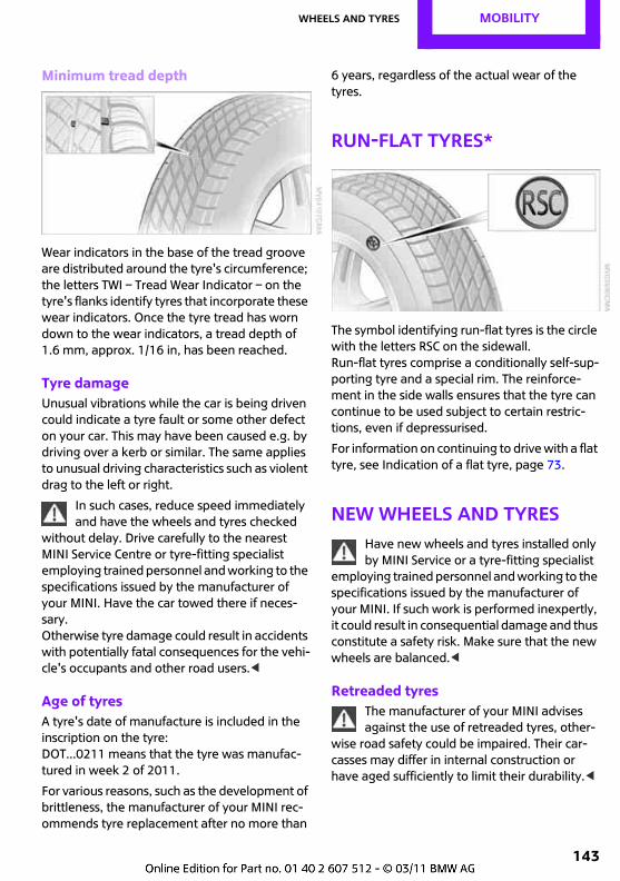
Wheels and tyres MOBILITY
143
Minimum tread depth
Wear indicators in the base of the tread groove are distributed around the tyre's circumference; the letters TWI – Tread Wear Indicator – on the tyre's flanks identify tyres that incorporate these wear indicators. Once the tyre tread has worn down to the wear indicators, a tread depth of 1.6 mm, approx. 1/16 in, has been reached.
Tyre damageUnusual vibrations while the car is being driven could indicate a tyre fault or some other defect on your car. This may have been caused e.g. by driving over a kerb or similar. The same applies to unusual driving characteristics such as violent drag to the left or right.
In such cases, reduce speed immediately and have the wheels and tyres checked
without delay. Drive carefully to the nearest MINI Service Centre or tyre-fitting specialist employing trained personnel and working to the specifications issued by the manufacturer of your MINI. Have the car towed there if neces-sary. Otherwise tyre damage could result in accidents with potentially fatal consequences for the vehi-cle's occupants and other road users.<
Age of tyresA tyre's date of manufacture is included in the inscription on the tyre: DOT...0211 means that the tyre was manufac-tured in week 2 of 2011.
For various reasons, such as the development of brittleness, the manufacturer of your MINI rec-ommends tyre replacement after no more than
6 years, regardless of the actual wear of the tyres.
Run-flat tyres*
The symbol identifying run-flat tyres is the circle with the letters RSC on the sidewall.Run-flat tyres comprise a conditionally self-sup-porting tyre and a special rim. The reinforce-ment in the side walls ensures that the tyre can continue to be used subject to certain restric-tions, even if depressurised.
For information on continuing to drive with a flat tyre, see Indication of a flat tyre, page 73.
New wheels and tyresHave new wheels and tyres installed only by MINI Service or a tyre-fitting specialist
employing trained personnel and working to the specifications issued by the manufacturer of your MINI. If such work is performed inexpertly, it could result in consequential damage and thus constitute a safety risk. Make sure that the new wheels are balanced.<
Retreaded tyresThe manufacturer of your MINI advises against the use of retreaded tyres, other-
wise road safety could be impaired. Their car-casses may differ in internal construction or have aged sufficiently to limit their durability.<
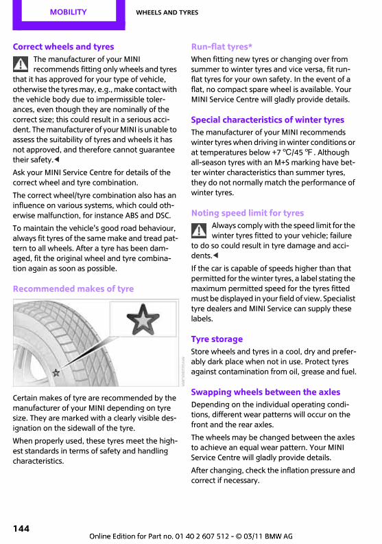
MOBILITY Wheels and tyres
144
Correct wheels and tyresThe manufacturer of your MINI recommends fitting only wheels and tyres
that it has approved for your type of vehicle, otherwise the tyres may, e.g., make contact with the vehicle body due to impermissible toler-ances, even though they are nominally of the correct size; this could result in a serious acci-dent. The manufacturer of your MINI is unable to assess the suitability of tyres and wheels it has not approved, and therefore cannot guarantee their safety.<
Ask your MINI Service Centre for details of the correct wheel and tyre combination.
The correct wheel/tyre combination also has an influence on various systems, which could oth-erwise malfunction, for instance ABS and DSC.
To maintain the vehicle's good road behaviour, always fit tyres of the same make and tread pat-tern to all wheels. After a tyre has been dam-aged, fit the original wheel and tyre combina-tion again as soon as possible.
Recommended makes of tyre
Certain makes of tyre are recommended by the manufacturer of your MINI depending on tyre size. They are marked with a clearly visible des-ignation on the sidewall of the tyre.
When properly used, these tyres meet the high-est standards in terms of safety and handling characteristics.
Run-flat tyres*When fitting new tyres or changing over from summer to winter tyres and vice versa, fit run-flat tyres for your own safety. In the event of a flat, no compact spare wheel is available. Your MINI Service Centre will gladly provide details.
Special characteristics of winter tyresThe manufacturer of your MINI recommends winter tyres when driving in winter conditions or at temperatures below +76/457. Although all-season tyres with an M+S marking have bet-ter winter characteristics than summer tyres, they do not normally match the performance of winter tyres.
Noting speed limit for tyresAlways comply with the speed limit for the winter tyres fitted to your vehicle; failure
to do so could result in tyre damage and acci-dents.<
If the car is capable of speeds higher than that permitted for the winter tyres, a label stating the maximum permitted speed for the tyres fitted must be displayed in your field of view. Specialist tyre dealers and MINI Service can supply these labels.
Tyre storageStore wheels and tyres in a cool, dry and prefer-ably dark place when not in use. Protect tyres against contamination from oil, grease and fuel.
Swapping wheels between the axlesDepending on the individual operating condi-tions, different wear patterns will occur on the front and the rear axles.
The wheels may be changed between the axles to achieve an equal wear pattern. Your MINI Service Centre will gladly provide details.
After changing, check the inflation pressure and correct if necessary.
Wheels and tyres MOBILITY
145
Snow chains*Only certain fine-link snow chains have been tested, found safe for use in traffic, and recom-mended by the manufacturer of your MINI. Details are available from your MINI Service Cen-tre.
Fit snow chains in pairs and only to front wheels with tyres of the following sizes:
> 195/60 R 16 M+S
When fitting, comply with the snow chain man-ufacturer's instructions. When snow chains are in use, do not exceed 50 km/h, approx. 30 mph.
Do not initialise the Run Flat Indicator if snow chains are fitted, as the instrument
might issue an incorrect reading. When driving with snow chains, it may be helpful to briefly deactivate DSC or activate DTC, see page 70.<
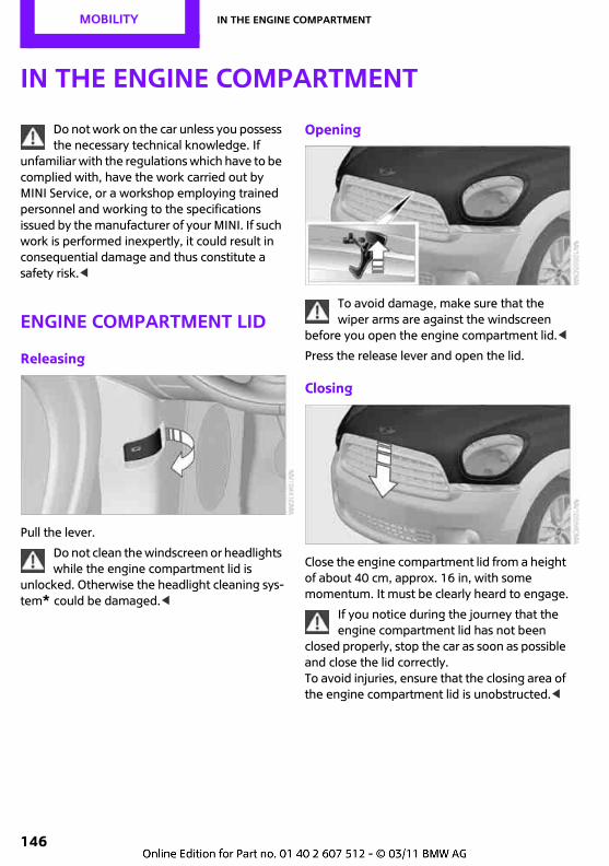
MOBILITY In the engine compartment
146
In the engine compartment
Do not work on the car unless you possess the necessary technical knowledge. If
unfamiliar with the regulations which have to be complied with, have the work carried out by MINI Service, or a workshop employing trained personnel and working to the specifications issued by the manufacturer of your MINI. If such work is performed inexpertly, it could result in consequential damage and thus constitute a safety risk.<
Engine compartment lid
Releasing
Pull the lever.
Do not clean the windscreen or headlights while the engine compartment lid is
unlocked. Otherwise the headlight cleaning sys-tem* could be damaged.<
Opening
To avoid damage, make sure that the wiper arms are against the windscreen
before you open the engine compartment lid.<
Press the release lever and open the lid.
Closing
Close the engine compartment lid from a height of about 40 cm, approx. 16 in, with some momentum. It must be clearly heard to engage.
If you notice during the journey that the engine compartment lid has not been
closed properly, stop the car as soon as possible and close the lid correctly.To avoid injuries, ensure that the closing area of the engine compartment lid is unobstructed.<
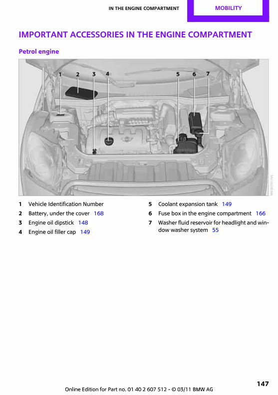
In the engine compartment MOBILITY
147
Important accessories in the engine compartment
Petrol engine
1 Vehicle Identification Number
2 Battery, under the cover 168
3 Engine oil dipstick 148
4 Engine oil filler cap 149
5 Coolant expansion tank 149
6 Fuse box in the engine compartment 166
7 Washer fluid reservoir for headlight and win-dow washer system 55
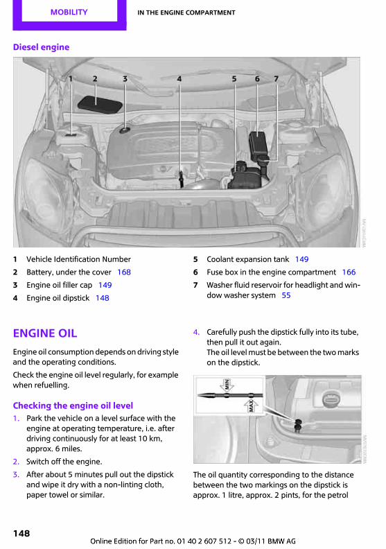
MOBILITY In the engine compartment
148
Diesel engine
1 Vehicle Identification Number
2 Battery, under the cover 168
3 Engine oil filler cap 149
4 Engine oil dipstick 148
5 Coolant expansion tank 149
6 Fuse box in the engine compartment 166
7 Washer fluid reservoir for headlight and win-dow washer system 55
Engine oilEngine oil consumption depends on driving style and the operating conditions.
Check the engine oil level regularly, for example when refuelling.
Checking the engine oil level1. Park the vehicle on a level surface with the
engine at operating temperature, i.e. after driving continuously for at least 10 km, approx. 6 miles.
2. Switch off the engine.
3. After about 5 minutes pull out the dipstick and wipe it dry with a non-linting cloth, paper towel or similar.
4. Carefully push the dipstick fully into its tube, then pull it out again. The oil level must be between the two marks on the dipstick.
The oil quantity corresponding to the distance between the two markings on the dipstick is approx. 1 litre, approx. 2 pints, for the petrol
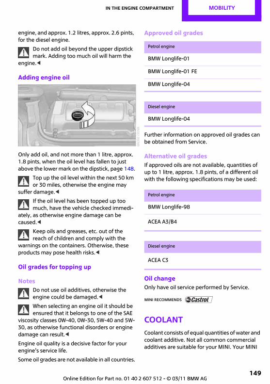
In the engine compartment MOBILITY
149
engine, and approx. 1.2 litres, approx. 2.6 pints, for the diesel engine.
Do not add oil beyond the upper dipstick mark. Adding too much oil will harm the
engine.<
Adding engine oil
Only add oil, and not more than 1 litre, approx. 1.8 pints, when the oil level has fallen to just above the lower mark on the dipstick, page 148.
Top up the oil level within the next 50 km or 30 miles, otherwise the engine may
suffer damage.<
If the oil level has been topped up too much, have the vehicle checked immedi-
ately, as otherwise engine damage can be caused.<
Keep oils and greases, etc. out of the reach of children and comply with the
warnings on the containers. Otherwise, these products may pose health risks.<
Oil grades for topping up
NotesDo not use oil additives, otherwise the engine could be damaged.<
When selecting an engine oil it should be ensured that it belongs to one of the SAE
viscosity classes 0W-40, 0W-30, 5W-40 and 5W-30, as otherwise functional disorders or engine damage can result.<
Engine oil quality is a decisive factor for your engine's service life.
Some oil grades are not available in all countries.
Approved oil grades
Further information on approved oil grades can be obtained from Service.
Alternative oil gradesIf approved oils are not available, quantities of up to 1 litre, approx. 1.8 pints, of a different oil with the following specifications may be used:
Oil changeOnly have oil service performed by Service.
CoolantCoolant consists of equal quantities of water and coolant additive. Not all common commercial additives are suitable for your MINI. Your MINI
Petrol engine
BMW Longlife-01
BMW Longlife-01 FE
BMW Longlife-04
Diesel engine
BMW Longlife-04
Petrol engine
BMW Longlife-98
ACEA A3/B4
Diesel engine
ACEA C3
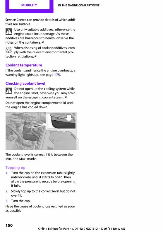
MOBILITY In the engine compartment
150
Service Centre can provide details of which addi-tives are suitable.
Use only suitable additives, otherwise the engine could incur damage. As these
additives are hazardous to health, observe the notes on the containers.<
When disposing of coolant additives, com-ply with the relevant environmental pro-
tection regulations.<
Coolant temperatureIf the coolant and hence the engine overheats, a warning light lights up, see page 175.
Checking coolant levelDo not open up the cooling system while the engine is hot, otherwise you may scald
yourself on the escaping coolant steam.<
Do not open the engine compartment lid until the engine has cooled down.
The coolant level is correct if it is between the Min. and Max. marks.
Topping up1. Turn the cap on the expansion tank slightly
anticlockwise until it starts to open, then allow the pressure to escape before opening it fully.
2. Slowly top up to the correct level but do not overfill.
3. Turn the cap.
Have the cause of coolant loss rectified as soon as possible.
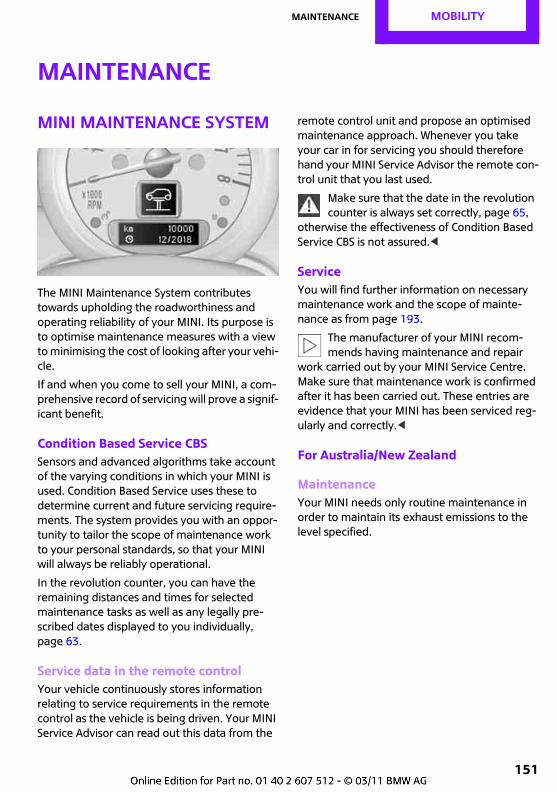
Maintenance MOBILITY
151
Maintenance
MINI Maintenance System
The MINI Maintenance System contributes towards upholding the roadworthiness and operating reliability of your MINI. Its purpose is to optimise maintenance measures with a view to minimising the cost of looking after your vehi-cle.
If and when you come to sell your MINI, a com-prehensive record of servicing will prove a signif-icant benefit.
Condition Based Service CBSSensors and advanced algorithms take account of the varying conditions in which your MINI is used. Condition Based Service uses these to determine current and future servicing require-ments. The system provides you with an oppor-tunity to tailor the scope of maintenance work to your personal standards, so that your MINI will always be reliably operational.
In the revolution counter, you can have the remaining distances and times for selected maintenance tasks as well as any legally pre-scribed dates displayed to you individually, page 63.
Service data in the remote controlYour vehicle continuously stores information relating to service requirements in the remote control as the vehicle is being driven. Your MINI Service Advisor can read out this data from the
remote control unit and propose an optimised maintenance approach. Whenever you take your car in for servicing you should therefore hand your MINI Service Advisor the remote con-trol unit that you last used.
Make sure that the date in the revolution counter is always set correctly, page 65,
otherwise the effectiveness of Condition Based Service CBS is not assured.<
ServiceYou will find further information on necessary maintenance work and the scope of mainte-nance as from page 193.
The manufacturer of your MINI recom-mends having maintenance and repair
work carried out by your MINI Service Centre. Make sure that maintenance work is confirmed after it has been carried out. These entries are evidence that your MINI has been serviced reg-ularly and correctly.<
For Australia/New Zealand
MaintenanceYour MINI needs only routine maintenance in order to maintain its exhaust emissions to the level specified.
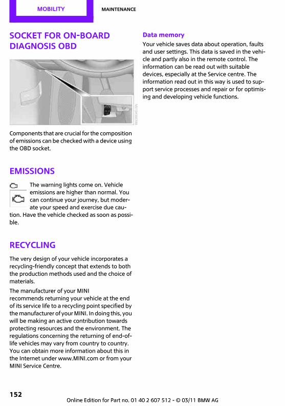
MOBILITY Maintenance
152
Socket for on-board diagnosis OBD
Components that are crucial for the composition of emissions can be checked with a device using the OBD socket.
EmissionsThe warning lights come on. Vehicle emissions are higher than normal. You can continue your journey, but moder-ate your speed and exercise due cau-
tion. Have the vehicle checked as soon as possi-ble.
RecyclingThe very design of your vehicle incorporates a recycling-friendly concept that extends to both the production methods used and the choice of materials.
The manufacturer of your MINI recommends returning your vehicle at the end of its service life to a recycling point specified by the manufacturer of your MINI. In doing this, you will be making an active contribution towards protecting resources and the environment. The regulations concerning the returning of end-of-life vehicles may vary from country to country. You can obtain more information about this in the Internet under www.MINI.com or from your MINI Service Centre.
Data memoryYour vehicle saves data about operation, faults and user settings. This data is saved in the vehi-cle and partly also in the remote control. The information can be read out with suitable devices, especially at the Service centre. The information read out in this way is used to sup-port service processes and repair or for optimis-ing and developing vehicle functions.
General care MOBILITY
153
General care
Care productsRegular cleaning and care make an appreciable contribution to the value maintenance of your MINI.
The manufacturer of your MINI recommends using parts and accessory prod-ucts for cleaning the car, which the manufac-turer of your MINI has approved for this purpose.
MINI Service will be glad to advise you on prod-ucts and services for the cleaning and care of your MINI.
Original MINI Care Products are subjected to material testing, laboratory testing and
practical tests and offer the best care and pro-tection for your vehicle.<
Do not use alcohol-based or solvent-based cleaning agents, as these could
cause damage.<
Cleaning agents can contain hazardous substances or constitute a health risk.
Comply with the warning and hazard avoidance instructions on the respective container. When cleaning the interior of the vehicle, leave doors or windows open. Never use substances not specifically intended for cleaning the vehicle.<
Exterior care
Washing the vehicleDuring the winter months in particular, wash the vehicle more frequently. Sub-
stantial deposits of dirt and road salt can cause damage to the vehicle.<
After washing the vehicle, drive it briefly and apply the brakes to dry them out; this
is necessary to prevent reduced braking effect, and also to avoid corrosion of the brake discs.<
Vehicle washesTextile vehicle washes are preferable.
Do not use high pressure car washes, as otherwise drops of water can penetrate at
the area around the windows.<
Before entering the car wash, check whether the system is suitable for your MINI. Take account of the following aspects:
> Vehicle dimensions, page 186
> If necessary: fold in exterior mirror, page 37
> Maximum allowable tyre width
Avoid car washes with guide rails higher than 10 cm, approx. 4 in, otherwise they
could damage the chassis and suspension.<
Preparations before driving into the vehicle wash:
> Unscrew the rod antenna.
> Deactivate rain sensor*, to avoid unin-tended wiping.
> Deactivate the rear window wiper and pro-tect it against damage. If necessary, please ask the operator of the vehicle wash about appropriate protective measures.
> Remove any add-on parts such as spoilers and telephone antennae that could be dam-aged.
> Insert the remote control in the ignition lock.
Automatic transmissionBefore entering the car wash, so that the vehicle can roll:
1. Inserting the remote control in the ignition lock, even if the vehicle has comfort access.
2. Move the selector lever to position N.
3. Release handbrake.
4. Switching off the engine.
5. Leaving the remote control in the ignition lock so that the vehicle can roll.
MOBILITY General care
154
Steam jets/high pressure cleaning jetsIf you use steam jet cleaners or high-pres-sure cleaners, make sure you maintain an
adequate distance and a temperature of 606/1407 at maximum.Too short a distance, too high pressure or too high temperature can damage certain parts of the vehicle or water could enter. Observe the operating instructions for the high pressure cleaning jet.<
Spray by using high pressure cleaner, not halting long at a point and maintaining a
distance of at least 30 cm, approx. 12 in, to sen-sors, such as e.g. Park Distance Control.<
Washing by handWhen washing the vehicle by hand, use plenty of water to which vehicle shampoo may be added. Clean the vehicle with a sponge or washing brush, applying only little pressure.
Before cleaning the windscreen, deacti-vate the rain sensor or switch off the igni-
tion to prevent unintentional operation of the wipers.<
Comply with local legislation on the wash-ing of vehicles by hand.<
HeadlightsDo not rub them when dry or use caustic or abrasive cleaning agents. Soak dirt or other deposits, e.g. dead insects, with shampoo and wash down with plenty of water.
Thaw out ice deposits using de-icer; do not use a scraper.
WindowsClean the outside and inside surfaces of win-dows and the surfaces of mirrors with glass cleaner.
Do not use quartz-based cleaning agents to clean mirrors.<
Wiper bladesClean with soap and water and change regularly to avoid the formation of streaks.
Wax and preservative residues and dirt contamination on the window glass cause
the formation of streaks during wiper operation and cause premature wear on the wiper blades and malfunctioning in the rain sensor.<
Care of paintworkRegular care helps preserve the value of the vehicle and protects the paintwork against long-term effects by substances that may damage the paintwork.
Environmental factors that vary from region to region could have adverse effects on the vehi-cle's paintwork and damage it. It is therefore important to adapt the frequency and scope of vehicle care procedures accordingly.
Remove particularly aggressive substances such as spilled fuel, oil, grease, brake fluid, tree sap and bird droppings without delay, otherwise the paintwork could be damaged.
Rectifying paintwork damageRepair stone damage or scratches imme-diately, depending on their severity, to
prevent rust from forming.<
The manufacturer of your MINI recommends having paintwork damages repaired by an expert, according to the factory specifications with original MINI paint material.
Protecting the paintworkProtective treatment is required if water no longer forms large droplets and runs off the clean paintwork surface. When applying protec-tive paintwork treatment, use only products containing carnauba or synthetic waxes.
Rubber sealsTreat only with water or with rubber care prod-ucts.
General care MOBILITY
155
Do no apply silicone sprays or other prod-ucts containing silicone to rubber seals, as
otherwise noise and damage could result.<
Chrome parts*Carefully clean parts such as the radiator grille or door handles with plenty of water and shampoo additive, especially whenever the car is exposed to the effects of road salt. Use chrome polish by way of additional treatment.
Light-metal alloy wheels*It is normal for the brakes to generate dust, which then forms deposits on the alloy wheels. Remove this dust at regular intervals with an acid-free rim cleaner.
Do not use any aggressive, acidic, highly alkaline or raw cleaning agents or steam-
jet cleaners over 606/1407, as otherwise they could cause damage.<
Exterior sensorsKeep the sensors on the vehicle exterior e.g. Park Distance Control, clean and free
from ice, to ensure full functioning.<
Trailer tow hitch with detachable ball head*Keep the ball head and the mounting on the vehicle clean. Grease or oil the bearings, sliding surfaces and balls with resin-free grease or oil.
When cleaning with a steam cleaner or high pressure cleaner, the ball head must be removed and the sealing stopper inserted. Do not clean the ball head with a steam cleaner or high pressure cleaner.
General care interior
Upholstery fabrics/fabric trimsClean regularly with a vacuum cleaner to remove surface dirt.
For more intensive cleaning, e.g. to remove drinks stains, use a soft sponge or a non-linting microfibre cloth in conjunction with a suitable interior cleaner. Observe the instructions on the pack.
Clean upholstery fabrics across a large area, right up to the seams. Avoid rubbing
them excessively.<
Open bur fasteners on trousers or other garments could damage the seat uphol-
stery. Ensure that bur fasteners are fastened.<
Leather/Leather panelling*The leather processed by the manufac-turer of your MINI is a high-quality natural
product. Slight variations in the grain pattern are one of the typical characteristics of authentic leather.<
Dust and road dirt works its way into the pores and folds, promoting abrasion and causing the leather surface to become prematurely brittle. You should therefore remove dust from the leather at regular intervals with a cloth or vac-uum cleaner.
Especially in case of a light coloured leather, see that it is de-dusted regularly as it tends to collect heavier contamination.
Treat the leather with a leather lotion twice a year, as dirt and grease will attack the leather's protective layer.
Carpets/floor mats*Make sure that pedal functions are not impaired during travel by floor mats, car-
pets or other objects.Do not place additional floor mats on top of existing floor mats or other objects.Only use floor mats which have been approved for use with the vehicle and can be securely fas-tened in place.If you remove floor mats, for cleaning for exam-ple, make sure that you fasten them securely back in place.<
Floor mats can be removed for cleaning.
MOBILITY General care
156
If floor carpets are more heavily soiled, use a microfibre cloth and water or a textile cleaning agent to clean them. In doing so, rub back and forth in the direction of travel, as otherwise the carpet can become tangled.
Interior plastic partsThese include:
> Imitation leather surface finishes
> Lamp lenses
> Display covers
> Matt parts
Clean with water and some solvent-free plastic cleaner.
Do not use any solvents such as alcohol, lacquer thinners, heavy-duty grease
removers, gasoline or similar; otherwise the sur-faces could be damaged.<
Decorative strips*Clean decorative strips exclusively with a moist cloth. Then rub dry with a soft cloth.
Seat beltsDirt on the seat belts will prevent them from being retracted properly and will therefore impair safety.
Do not dry clean the seat belts, otherwise the fabric may be destroyed.<
DisplaysFor the cleaning of displays, such as radio or dis-play elements, a cleaning cloth or a soft, non-scratching, lint-free cloth.
Avoid applying excessive pressure when cleaning displays, otherwise they could be
damaged.<
Do not use any chemical or abrasive domestic cleaning agents. Keep all liquids
and any moisture away from the set. Surfaces or electrical components might otherwise be cor-roded or damaged.<
CD/DVD drivesDo not use cleaning CDs, as these could damage drive components.<
Placing the vehicle in storageIf you plan not to use your vehicle for longer than three months, please consult your MINI Service Centre or a workshop which works according to the MINI manufacturer's specifica-tions.
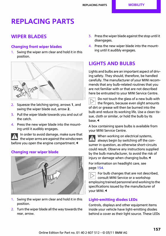
Replacing parts MOBILITY
157
Replacing parts
Wiper blades
Changing front wiper blades1. Swing the wiper arm clear and hold it in this
position.
2. Squeeze the latching spring, arrows 1, and swing the wiper blade out, arrow 2.
3. Pull the wiper blade towards you and out of the catch.
4. Press the new wiper blade into the mount-ing until it audibly engages.
In order to avoid damage, make sure that the wiper arms are against the windscreen
before you open the engine compartment.<
Changing rear wiper blade
1. Swing the wiper arm clear and hold it in this position.
2. Turn the wiper blade all the way towards the rear, arrow.
3. Press the wiper blade against the stop until it disengages.
4. Press the new wiper blade into the mount-ing until it audibly engages.
Lights and bulbsLights and bulbs are an important aspect of driv-ing safety. They should, therefore, be handled carefully. The manufacturer of your MINI recom-mends that any bulb-related routines that you are not familiar with or that are not described here be entrusted to your MINI Service Centre.
Do not touch the glass of a new bulb with the fingers, because even slight amounts
of dirt or grease will then be burned into the bulb and reduce its working life. Use a clean tis-sue, cloth or similar, or hold the bulb by its base.<
A box containing spare bulbs is available from your MINI Service Centre.
When working on electrical systems, always begin by switching off the con-
sumer in question, as otherwise short-circuits could result. Observe any instructions supplied by the bulb manufacturer, to avoid the risk of injury or damage when changing bulbs.<
For information on headlight care, see page 154.
For bulb changes that are not described, consult MINI Service or a workshop
employing trained personnel and working to the specifications issued by the manufacturer of your MINI.<
Light-emitting diodes LEDsControls, displays and other equipment items inside your vehicle have light-emitting diodes behind a cover as their light source. These LEDs
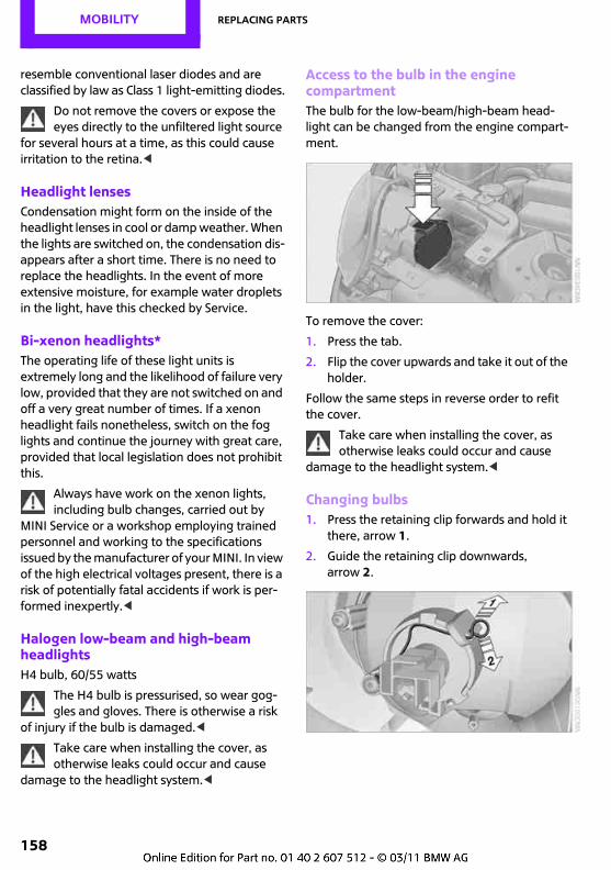
MOBILITY Replacing parts
158
resemble conventional laser diodes and are classified by law as Class 1 light-emitting diodes.
Do not remove the covers or expose the eyes directly to the unfiltered light source
for several hours at a time, as this could cause irritation to the retina.<
Headlight lensesCondensation might form on the inside of the headlight lenses in cool or damp weather. When the lights are switched on, the condensation dis-appears after a short time. There is no need to replace the headlights. In the event of more extensive moisture, for example water droplets in the light, have this checked by Service.
Bi-xenon headlights*The operating life of these light units is extremely long and the likelihood of failure very low, provided that they are not switched on and off a very great number of times. If a xenon headlight fails nonetheless, switch on the fog lights and continue the journey with great care, provided that local legislation does not prohibit this.
Always have work on the xenon lights, including bulb changes, carried out by
MINI Service or a workshop employing trained personnel and working to the specifications issued by the manufacturer of your MINI. In view of the high electrical voltages present, there is a risk of potentially fatal accidents if work is per-formed inexpertly.<
Halogen low-beam and high-beam headlightsH4 bulb, 60/55 watts
The H4 bulb is pressurised, so wear gog-gles and gloves. There is otherwise a risk
of injury if the bulb is damaged.<
Take care when installing the cover, as otherwise leaks could occur and cause
damage to the headlight system.<
Access to the bulb in the engine compartmentThe bulb for the low-beam/high-beam head-light can be changed from the engine compart-ment.
To remove the cover:
1. Press the tab.
2. Flip the cover upwards and take it out of the holder.
Follow the same steps in reverse order to refit the cover.
Take care when installing the cover, as otherwise leaks could occur and cause
damage to the headlight system.<
Changing bulbs1. Press the retaining clip forwards and hold it
there, arrow 1.
2. Guide the retaining clip downwards, arrow 2.
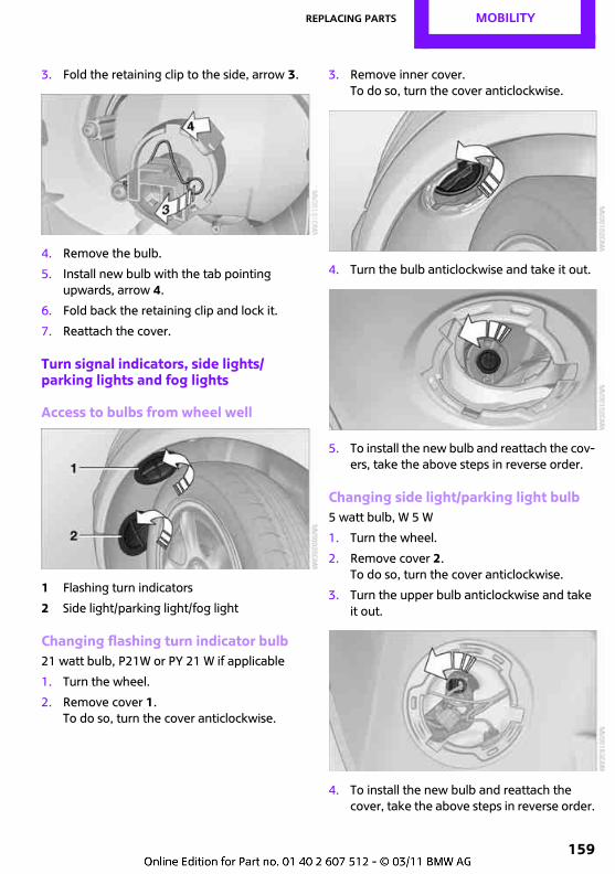
Replacing parts MOBILITY
159
3. Fold the retaining clip to the side, arrow 3.
4. Remove the bulb.
5. Install new bulb with the tab pointing upwards, arrow 4.
6. Fold back the retaining clip and lock it.
7. Reattach the cover.
Turn signal indicators, side lights/parking lights and fog lights
Access to bulbs from wheel well
1 Flashing turn indicators
2 Side light/parking light/fog light
Changing flashing turn indicator bulb21 watt bulb, P21W or PY 21 W if applicable
1. Turn the wheel.
2. Remove cover 1.To do so, turn the cover anticlockwise.
3. Remove inner cover.To do so, turn the cover anticlockwise.
4. Turn the bulb anticlockwise and take it out.
5. To install the new bulb and reattach the cov-ers, take the above steps in reverse order.
Changing side light/parking light bulb5 watt bulb, W 5 W
1. Turn the wheel.
2. Remove cover 2.To do so, turn the cover anticlockwise.
3. Turn the upper bulb anticlockwise and take it out.
4. To install the new bulb and reattach the cover, take the above steps in reverse order.
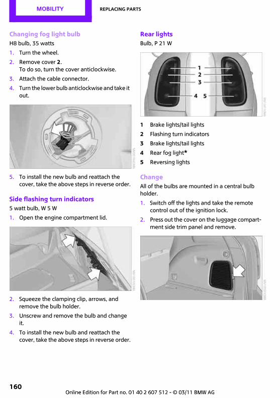
MOBILITY Replacing parts
160
Changing fog light bulbH8 bulb, 35 watts
1. Turn the wheel.
2. Remove cover 2.To do so, turn the cover anticlockwise.
3. Attach the cable connector.
4. Turn the lower bulb anticlockwise and take it out.
5. To install the new bulb and reattach the cover, take the above steps in reverse order.
Side flashing turn indicators5 watt bulb, W 5 W
1. Open the engine compartment lid.
2. Squeeze the clamping clip, arrows, and remove the bulb holder.
3. Unscrew and remove the bulb and change it.
4. To install the new bulb and reattach the cover, take the above steps in reverse order.
Rear lightsBulb, P 21 W
1 Brake lights/tail lights
2 Flashing turn indicators
3 Brake lights/tail lights
4 Rear fog light*5 Reversing lights
ChangeAll of the bulbs are mounted in a central bulb holder.
1. Switch off the lights and take the remote control out of the ignition lock.
2. Press out the cover on the luggage compart-ment side trim panel and remove.
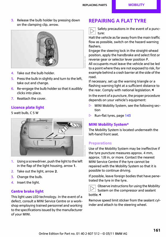
Replacing parts MOBILITY
161
3. Release the bulb holder by pressing down on the clamping clip, arrow.
4. Take out the bulb holder.
5. Press the bulb in slightly and turn to the left, take out and change.
6. Re-engage the bulb holder so that it audibly clicks into place.
7. Reattach the cover.
Licence plate light5 watt bulb, C 5 W
1. Using a screwdriver, push the light to the left in the flap of the light housing, arrow 1.
2. Take out the light, arrow 2.
3. Change the bulb.
4. Insert the light.
Centre brake lightThis light uses LED technology. In the event of a defect, consult a MINI Service Centre or a work-shop employing trained personnel and working to the specifications issued by the manufacturer of your MINI.
Repairing a flat tyreSafety precautions in the event of a punc-ture:
Halt the vehicle as far away from the main traffic flow as possible, switch on the hazard warning flashers.Engage the steering lock in the straight-ahead position, apply the handbrake and select first or reverse gear or selector lever position P.All occupants must leave the vehicle and be led to a point where they are not exposed to risk, for example behind a crash barrier at the side of the road.If necessary, set up the warning triangle or a flashing warning light at a sufficient distance to the rear. Comply with national legislation.<
In the event of a puncture, the proper procedure depends on your vehicle's equipment:
> MINI Mobility System, see the following sec-tion
> Run-flat tyres, page 143
MINI Mobility System*The Mobility System is located underneath the left-hand front seat.
PreparationsUse of the Mobility System may be ineffective if the tyre puncture measures approx. 4 mm, approx. 1/8 in, or more. Contact the nearest MINI Service Centre if the tyre cannot be repaired with the Mobility System so that it is possible to continue driving.
If possible, leave foreign bodies that have pene-trated the tyre in the tyre.
Observe instructions for using the Mobility System on the compressor and sealant
bottle.<
Remove speed limit sticker from the sealant cyl-inder and attach to the steering wheel.
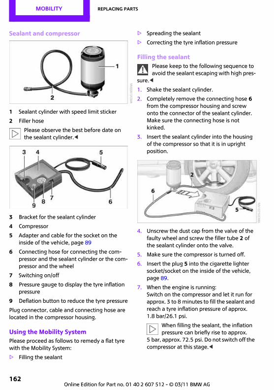
MOBILITY Replacing parts
162
Sealant and compressor
1 Sealant cylinder with speed limit sticker
2 Filler hose
Please observe the best before date on the sealant cylinder.<
3 Bracket for the sealant cylinder
4 Compressor
5 Adapter and cable for the socket on the inside of the vehicle, page 89
6 Connecting hose for connecting the com-pressor and the sealant cylinder or the com-pressor and the wheel
7 Switching on/off
8 Pressure gauge to display the tyre inflation pressure
9 Deflation button to reduce the tyre pressure
Plug connector, cable and connecting hose are located in the compressor housing.
Using the Mobility SystemPlease proceed as follows to remedy a flat tyre with the Mobility System:
> Filling the sealant
> Spreading the sealant
> Correcting the tyre inflation pressure
Filling the sealantPlease keep to the following sequence to avoid the sealant escaping with high pres-
sure.<
1. Shake the sealant cylinder.
2. Completely remove the connecting hose 6 from the compressor housing and screw onto the connector of the sealant cylinder. Make sure the connecting hose is not kinked.
3. Insert the sealant cylinder into the housing of the compressor so that it is in upright position.
4. Unscrew the dust cap from the valve of the faulty wheel and screw the filler tube 2 of the sealant cylinder onto the valve.
5. Make sure the compressor is turned off.
6. Insert the plug 5 into the cigarette lighter socket/socket on the inside of the vehicle, page 89.
7. When the engine is running: Switch on the compressor and let it run for approx. 3 to 8 minutes to fill the sealant and reach a tyre inflation pressure of approx. 1.8 bar/26.1 psi.
When filling the sealant, the inflation pressure can briefly rise to approx.
5 bar, approx. 72.5 psi. Do not switch off the compressor at this stage.<
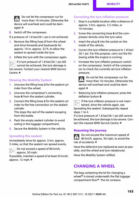
Replacing parts MOBILITY
163
Do not let the compressor run for more than 10 minutes. Otherwise the
device will overheat and could be dam-aged.<
8. Switch off the compressor.
If a pressure of 1.8 bar/26.1 psi is not achieved:
1. Remove the filling hose 2 from the wheel and drive forwards and backwards for approx. 10 m, approx. 32 ft, to allow the sealant to spread inside the tyre.
2. Inflate the tyre with the compressor again.
If a tyre pressure of 1.8 bar/26.1 psi still cannot be achieved, the tyre damage is
too severe. Contact your nearest MINI Service Centre.<
Stowing the Mobility System1. Unscrew the filling hose 2 for the sealant cyl-
inder from the wheel.
2. Unscrew the compressor's connecting hose 6 from the sealant cylinder.
3. Connect the filling hose 2 for the sealant cyl-inder to the free connection on the sealant cylinder.This stops the rest of the sealant escaping from the bottle.
4. Pack the empty sealant cylinder to avoid soiling in the luggage compartment.
5. Secure the Mobility System in the vehicle.
Spreading the sealantImmediately drive for approx. 5 km, approx. 3 miles, so that the sealant can spread evenly.
Do not exceed a speed of 80 km/h, approx. 50 mph.
If possible, maintain a speed of at least 20 km/h, approx. 12 mph.<
Correcting the tyre inflation pressure1. Stop in a suitable location after a distance of
approx. 5 km, approx. 3.5 miles, or 10 minutes.
2. Screw the connecting hose 6 of the com-pressor directly onto the tyre valve.
3. Insert the plug 5 into the socket on the inside of the vehicle.
4. Correct the tyre inflation pressure to 1.8 bar/26.1 psi. For this purpose, carry out the fol-lowing while the engine is running:
> Increase the tyre inflation pressure: switch on the compressor. Switch of the compres-sor to check the currently set tyre inflation pressure.
Do not let the compressor run for more than 10 minutes. Otherwise the
device will overheat and could be dam-aged.<
> Reducing tyre inflation pressure: press the deflation button 9.
If the tyre inflation pressure is not main-tained, drive the vehicle again, see
Spreading the sealant. Subsequently repeat steps 1 to 4.If a tyre pressure of 1.8 bar/26.1 psi still cannot be achieved, the tyre damage is too severe. Con-tact the nearest MINI Service Centre.<
Resuming the journeyDo not exceed the maximum speed of 80 km/h, approx. 50 mph, to avoid the
risk of accidents.<
Have the defective tyre replaced as soon as pos-sible, and the wheel and tyre rebalanced.
Have the Mobility System refilled.
Changing a wheelThe bag containing the kit for changing a wheel* is stored underneath the flat luggage compartment floor*. The kit contains:
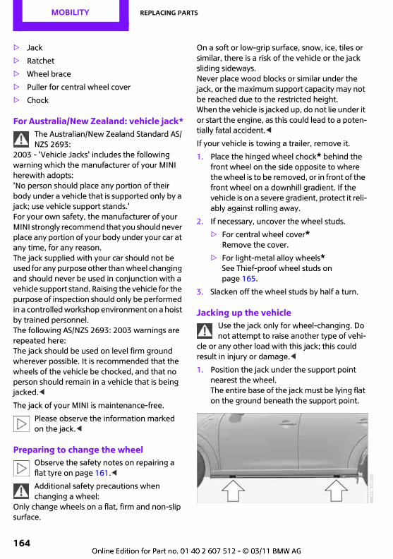
MOBILITY Replacing parts
164
> Jack
> Ratchet
> Wheel brace
> Puller for central wheel cover
> Chock
For Australia/New Zealand: vehicle jack*The Australian/New Zealand Standard AS/NZS 2693:
2003 - 'Vehicle Jacks' includes the following warning which the manufacturer of your MINI herewith adopts:'No person should place any portion of their body under a vehicle that is supported only by a jack; use vehicle support stands.'For your own safety, the manufacturer of your MINI strongly recommend that you should never place any portion of your body under your car at any time, for any reason.The jack supplied with your car should not be used for any purpose other than wheel changing and should never be used in conjunction with a vehicle support stand. Raising the vehicle for the purpose of inspection should only be performed in a controlled workshop environment on a hoist by trained personnel.The following AS/NZS 2693: 2003 warnings are repeated here:The jack should be used on level firm ground wherever possible. It is recommended that the wheels of the vehicle be chocked, and that no person should remain in a vehicle that is being jacked.<
The jack of your MINI is maintenance-free.
Please observe the information marked on the jack.<
Preparing to change the wheelObserve the safety notes on repairing a flat tyre on page 161.<
Additional safety precautions when changing a wheel:
Only change wheels on a flat, firm and non-slip surface.
On a soft or low-grip surface, snow, ice, tiles or similar, there is a risk of the vehicle or the jack sliding sideways. Never place wood blocks or similar under the jack, or the maximum support capacity may not be reached due to the restricted height. When the vehicle is jacked up, do not lie under it or start the engine, as this could lead to a poten-tially fatal accident.<
If your vehicle is towing a trailer, remove it.
1. Place the hinged wheel chock* behind the front wheel on the side opposite to where the wheel is to be removed, or in front of the front wheel on a downhill gradient. If the vehicle is on a severe gradient, protect it reli-ably against rolling away.
2. If necessary, uncover the wheel studs.
> For central wheel cover*Remove the cover.
> For light-metal alloy wheels*See Thief-proof wheel studs on page 165.
3. Slacken off the wheel studs by half a turn.
Jacking up the vehicleUse the jack only for wheel-changing. Do not attempt to raise another type of vehi-
cle or any other load with this jack; this could result in injury or damage.<
1. Position the jack under the support point nearest the wheel.The entire base of the jack must be lying flat on the ground beneath the support point.
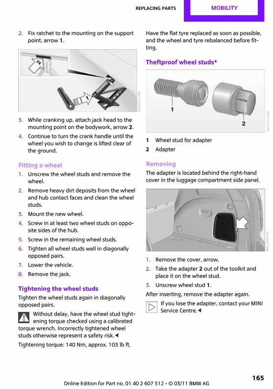
Replacing parts MOBILITY
165
2. Fix ratchet to the mounting on the support point, arrow 1.
3. While cranking up, attach jack head to the mounting point on the bodywork, arrow 2.
4. Continue to turn the crank handle until the wheel you wish to change is lifted clear of the ground.
Fitting a wheel1. Unscrew the wheel studs and remove the
wheel.
2. Remove heavy dirt deposits from the wheel and hub contact faces and clean the wheel studs.
3. Mount the new wheel.
4. Screw in at least two wheel studs on oppo-site sides of the hub.
5. Screw in the remaining wheel studs.
6. Tighten all wheel studs well in diagonally opposed pairs.
7. Lower the vehicle.
8. Remove the jack.
Tightening the wheel studsTighten the wheel studs again in diagonally opposed pairs.
Without delay, have the wheel stud tight-ening torque checked using a calibrated
torque wrench. Incorrectly tightened wheel studs otherwise represent a safety risk.<
Tightening torque: 140 Nm, approx. 103 lb ft.
Have the flat tyre replaced as soon as possible, and the wheel and tyre rebalanced before fit-ting.
Theftproof wheel studs*
1 Wheel stud for adapter
2 Adapter
RemovingThe adapter is located behind the right-hand cover in the luggage compartment side panel.
1. Remove the cover, arrow.
2. Take the adapter 2 out of the toolkit and place it on the wheel stud.
3. Unscrew wheel stud 1.
After inserting, remove the adapter again.
If you lose the adapter, contact your MINI Service Centre.<
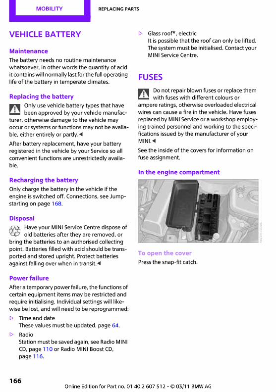
MOBILITY Replacing parts
166
Vehicle battery
MaintenanceThe battery needs no routine maintenance whatsoever, in other words the quantity of acid it contains will normally last for the full operating life of the battery in temperate climates.
Replacing the batteryOnly use vehicle battery types that have been approved by your vehicle manufac-
turer, otherwise damage to the vehicle may occur or systems or functions may not be availa-ble, either entirely or partly.<
After battery replacement, have your battery registered in the vehicle by your Service so all convenient functions are unrestrictedly availa-ble.
Recharging the batteryOnly charge the battery in the vehicle if the engine is switched off. Connections, see Jump-starting on page 168.
DisposalHave your MINI Service Centre dispose of old batteries after they are removed, or
bring the batteries to an authorised collecting point. Batteries filled with acid should be trans-ported and stored upright. Protect batteries against falling over when in transit.<
Power failureAfter a temporary power failure, the functions of certain equipment items may be restricted and require initialising. Individual settings will like-wise be lost, and will need to be reprogrammed:
> Time and date These values must be updated, page 64.
> RadioStation must be saved again, see Radio MINI CD, page 110 or Radio MINI Boost CD, page 116.
> Glass roof*, electricIt is possible that the roof can only be lifted. The system must be initialised. Contact your MINI Service Centre.
FusesDo not repair blown fuses or replace them with fuses with different colours or
ampere ratings, otherwise overloaded electrical wires can cause a fire in the vehicle. Have fuses replaced by MINI Service or a workshop employ-ing trained personnel and working to the speci-fications issued by the manufacturer of your MINI.<
See the inside of the covers for information on fuse assignment.
In the engine compartment
To open the coverPress the snap-fit catch.
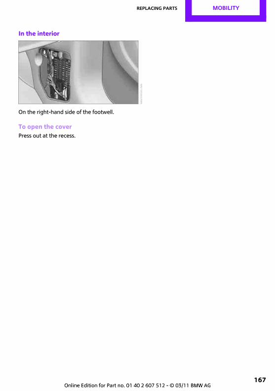
Replacing parts MOBILITY
167
In the interior
On the right-hand side of the footwell.
To open the coverPress out at the recess.
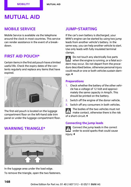
MOBILITY Mutual aid
168
Mutual aid
Mobile ServiceMobile Service is available via the telephone around the clock in most countries. This service can render assistance in the event of a break-down.
First aid pouch*Certain items in the first aid pouch have a limited useful life. Check the expiry dates of the con-tents regularly and replace any items that have expired.
The first-aid pouch is located on the luggage compartment floor on the left-hand side trim panel or under the luggage compartment floor.
Warning triangle*
In the luggage area under the load edge.
To remove the triangle, open the two fasteners.
Jump-startingIf the car's own battery is discharged, your MINI's engine can be started by using two jump leads from another vehicle's battery. In the same way, you can help another vehicle to start. Use only leads with fully insulated terminal clamps.
Do not touch any electrically live parts when the engine is running, or a fatal acci-
dent may occur. Do not depart from the proce-dure described below, otherwise personal injury could result or one or both vehicles sustain dam-age.<
Preparations1. Check whether the battery of the other vehi-
cle has a voltage of 12 Volt and approxi-mately the same capacity in Amp/h. This should be printed on the battery.
2. Switch off the engine of the donor vehicle.
3. Switch off any consumers in both vehicles.
The bodies of the two vehicles must not make contact, otherwise there is the risk
of a short-circuit.<
Connecting the jump leadsConnect the jump leads in the correct order to avoid sparks that could cause
injury.<
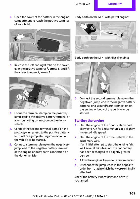
Mutual aid MOBILITY
169
1. Open the cover of the battery in the engine compartment to reach the positive terminal of your MINI.
2. Release the left and right tabs on the cover over the positive terminal*, arrow 1, and lift the cover to open it, arrow 2.
3. Connect a terminal clamp on the positive/+ jump lead to the positive battery terminal or a jump-starting connection on the donor vehicle.
4. Connect the second terminal clamp on the positive/+ jump lead to the positive battery terminal or a jump-starting connection on the vehicle to be started.
5. Connect a terminal clamp on the negative/– jump lead to the negative battery terminal or the engine or body earth connection on the donor vehicle.
Body earth on the MINI with petrol engine:
Body earth on the MINI with diesel engine:
6. Connect the second terminal clamp on the negative/– jump lead to the negative battery terminal or a ground/earth connection on the engine or body of the vehicle to be started.
Starting the engine1. Start the engine of the donor vehicle and
allow it to run for a few minutes at a slightly increased idle speed.
2. Start the engine of the other vehicle in the customary way. If an initial attempt to start the engine fails, wait several minutes until the flat battery has been recharged to a slightly greater degree.
3. Allow the engines to run for a few minutes.
4. Disconnect the jump leads in the opposite order from that in which they were originally attached.
Check the battery if necessary and have it recharged.
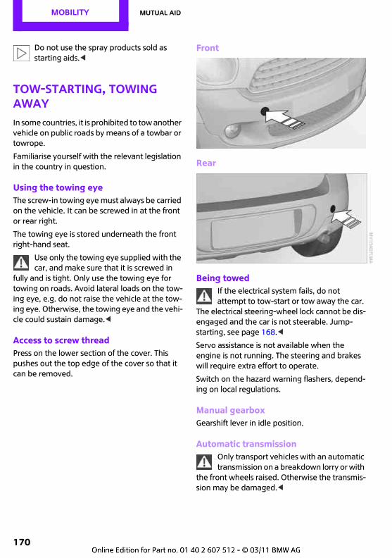
MOBILITY Mutual aid
170
Do not use the spray products sold as starting aids.<
Tow-starting, towing awayIn some countries, it is prohibited to tow another vehicle on public roads by means of a towbar or towrope.
Familiarise yourself with the relevant legislation in the country in question.
Using the towing eyeThe screw-in towing eye must always be carried on the vehicle. It can be screwed in at the front or rear right.
The towing eye is stored underneath the front right-hand seat.
Use only the towing eye supplied with the car, and make sure that it is screwed in
fully and is tight. Only use the towing eye for towing on roads. Avoid lateral loads on the tow-ing eye, e.g. do not raise the vehicle at the tow-ing eye. Otherwise, the towing eye and the vehi-cle could sustain damage.<
Access to screw threadPress on the lower section of the cover. This pushes out the top edge of the cover so that it can be removed.
Front
Rear
Being towedIf the electrical system fails, do not attempt to tow-start or tow away the car.
The electrical steering-wheel lock cannot be dis-engaged and the car is not steerable. Jump-starting, see page 168.<
Servo assistance is not available when the engine is not running. The steering and brakes will require extra effort to operate.
Switch on the hazard warning flashers, depend-ing on local regulations.
Manual gearboxGearshift lever in idle position.
Automatic transmissionOnly transport vehicles with an automatic transmission on a breakdown lorry or with
the front wheels raised. Otherwise the transmis-sion may be damaged.<
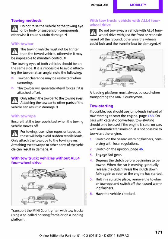
Mutual aid MOBILITY
171
Towing methodsDo not raise the vehicle at the towing eye or by body or suspension components,
otherwise it could sustain damage.<
With towbarThe towing vehicle must not be lighter than the towed vehicle, otherwise it may
be impossible to maintain control.<
The towing eyes of both vehicles should be on the same side. If it is impossible to avoid attach-ing the towbar at an angle, note the following:
> Towbar clearance may be restricted when cornering.
> The towbar will generate lateral forces if it is attached offset.
Only attach the towbar to the towing eyes. Attaching the towbar to other parts of the
vehicle can result in damage.<
With towropeEnsure that the towrope is taut when the towing vehicle moves off.
For towing, use nylon ropes or tapes, as these will help avoid sudden tensile loads.
Only attach the towrope to the towing eyes. Attaching the towrope to other parts of the vehi-cle can result in damage.<
With tow truck: vehicles without ALL4 four-wheel drive
Transport the MINI Countryman with tow trucks using a so-called hoisting frame or on a loading platform.
With tow truck: vehicle with ALL4 four-wheel drive
Do not tow away a vehicle with ALL4 four-wheel drive with just the front or rear axle
raised off the ground, otherwise the wheels could lock and the transfer box be damaged.<
A loading platform must always be used when transporting the MINI Countryman.
Tow-startingIf possible, you should use jump leads instead of tow-starting to start the engine, page 168. On cars with catalytic converters, tow-starting should only be used if the engine is cold; on cars with automatic transmission, it is not possible to tow-start the engine.
1. Switch on the hazard warning flashers, com-plying with local regulations.
2. Switch on the ignition, page 46.
3. Engage 3rd gear.
4. Depress the clutch before beginning to be towed. When the car is moving, gradually release the clutch. Press the clutch down fully again as soon as the engine has started.
5. Halt in a suitable place, remove the towbar or towrope and switch off the hazard warn-ing flashers.
6. Have the vehicle checked.
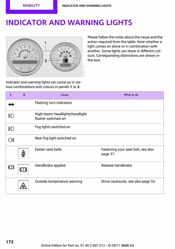
MOBILITY Indicator and warning lights
172
Indicator and warning lights
Indicator and warning lights can come on in var-ious combinations and colours in panels 1 or 2.
Please follow the notes about the cause and the action required from the table. Note whether a light comes on alone or in combination with another. Some lights can show in different col-ours. Corresponding distinctions are drawn in the text.
1 2 Cause What to do
Flashing turn indicators
High-beam headlights/headlight flasher switched on
Fog lights switched on
Rear fog light switched on
Fasten seat belts Fastening your seat belt, see also page 37.
Handbrake applied Release handbrake.
Outside temperature warning Drive cautiously, see also page 59.

Indicator and warning lights MOBILITY
173
Lights up briefly:
Approx. 8 litres, approx. 1.8 gal, of fuel left in the tank
Remains on:
Remaining operating range is no more than 50 km, approx. 30 miles, page 58
Engine refuses to start Depress the brake or clutch prepara-tory to starting the engine, page 46.
Ignition switched on and driver's door open
Switch off the ignition, page 46, or close the driver's door.
Lights still switched on
Parking lights switched on
Preheat, see page 47
Door open
Engine compartment lid open
Window washer fluid level too low Top up the washer fluid as soon as possible, page 55.
1 2 Cause What to do
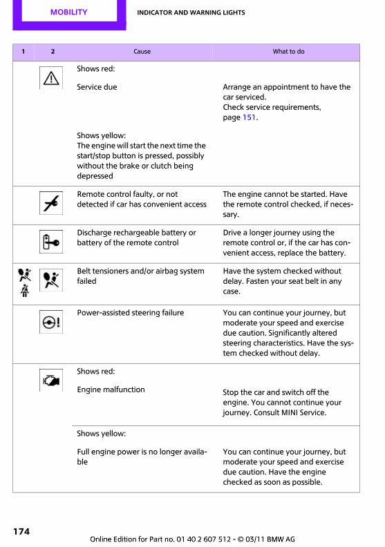
MOBILITY Indicator and warning lights
174
Shows red:
Service due Arrange an appointment to have the car serviced.Check service requirements, page 151.
Shows yellow:The engine will start the next time the start/stop button is pressed, possibly without the brake or clutch being depressed
Remote control faulty, or not detected if car has convenient access
The engine cannot be started. Have the remote control checked, if neces-sary.
Discharge rechargeable battery or battery of the remote control
Drive a longer journey using the remote control or, if the car has con-venient access, replace the battery.
Belt tensioners and/or airbag system failed
Have the system checked without delay. Fasten your seat belt in any case.
Power-assisted steering failure You can continue your journey, but moderate your speed and exercise due caution. Significantly altered steering characteristics. Have the sys-tem checked without delay.
Shows red:
Engine malfunction Stop the car and switch off the engine. You cannot continue your journey. Consult MINI Service.
Shows yellow:
Full engine power is no longer availa-ble
You can continue your journey, but moderate your speed and exercise due caution. Have the engine checked as soon as possible.
1 2 Cause What to do
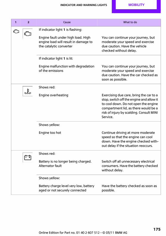
Indicator and warning lights MOBILITY
175
If indicator light 1 is flashing:
Engine fault under high load. High engine load will result in damage to the catalytic converter
You can continue your journey, but moderate your speed and exercise due caution. Have the vehicle checked without delay.
If indicator light 1 is lit:
Engine malfunction with degradation of the emissions
You can continue your journey, but moderate your speed and exercise due caution. Have the car checked as soon as possible.
Shows red:
Engine overheating Exercising due care, bring the car to a stop, switch off the engine and allow it to cool down. Do not open the engine compartment lid, as there would be a risk of injury by scalding. Consult MINI Service.
Shows yellow:
Engine too hot Continue driving at more moderate speed so that the engine can cool down. Have the engine checked with-out delay if the situation reoccurs.
Shows red:
Battery is no longer being charged. Alternator fault
Switch off all unnecessary electrical consumers. Have the battery checked without delay.
Shows yellow:
Battery charge level very low, battery aged or not securely connected
Have the battery checked as soon as possible.
1 2 Cause What to do
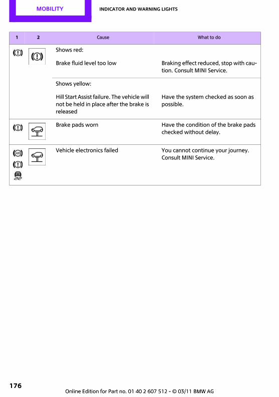
MOBILITY Indicator and warning lights
176
Shows red:
Brake fluid level too low Braking effect reduced, stop with cau-tion. Consult MINI Service.
Shows yellow:
Hill Start Assist failure. The vehicle will not be held in place after the brake is released
Have the system checked as soon as possible.
Brake pads worn Have the condition of the brake pads checked without delay.
Vehicle electronics failed You cannot continue your journey. Consult MINI Service.
1 2 Cause What to do
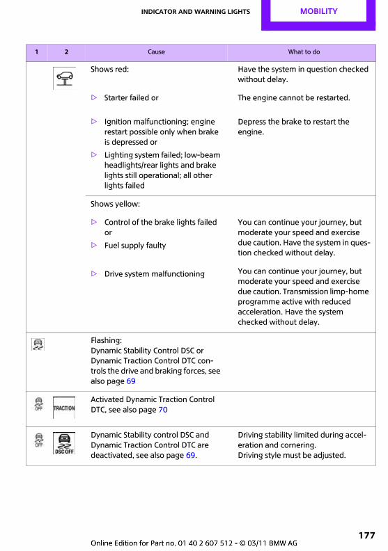
Indicator and warning lights MOBILITY
177
Shows red: Have the system in question checked without delay.
> Starter failed or The engine cannot be restarted.
> Ignition malfunctioning; engine restart possible only when brake is depressed or
> Lighting system failed; low-beam headlights/rear lights and brake lights still operational; all other lights failed
Depress the brake to restart the engine.
Shows yellow:
> Control of the brake lights failed or
> Fuel supply faulty
You can continue your journey, but moderate your speed and exercise due caution. Have the system in ques-tion checked without delay.
> Drive system malfunctioning You can continue your journey, but moderate your speed and exercise due caution. Transmission limp-home programme active with reduced acceleration. Have the system checked without delay.
Flashing:Dynamic Stability Control DSC or Dynamic Traction Control DTC con-trols the drive and braking forces, see also page 69
Activated Dynamic Traction Control DTC, see also page 70
Dynamic Stability control DSC and Dynamic Traction Control DTC are deactivated, see also page 69.
Driving stability limited during accel-eration and cornering. Driving style must be adjusted.
1 2 Cause What to do
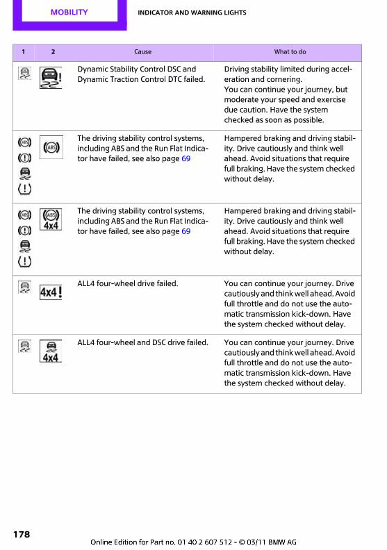
MOBILITY Indicator and warning lights
178
Dynamic Stability Control DSC and Dynamic Traction Control DTC failed.
Driving stability limited during accel-eration and cornering.You can continue your journey, but moderate your speed and exercise due caution. Have the system checked as soon as possible.
The driving stability control systems, including ABS and the Run Flat Indica-tor have failed, see also page 69
Hampered braking and driving stabil-ity. Drive cautiously and think well ahead. Avoid situations that require full braking. Have the system checked without delay.
The driving stability control systems, including ABS and the Run Flat Indica-tor have failed, see also page 69
Hampered braking and driving stabil-ity. Drive cautiously and think well ahead. Avoid situations that require full braking. Have the system checked without delay.
ALL4 four-wheel drive failed. You can continue your journey. Drive cautiously and think well ahead. Avoid full throttle and do not use the auto-matic transmission kick-down. Have the system checked without delay.
ALL4 four-wheel and DSC drive failed. You can continue your journey. Drive cautiously and think well ahead. Avoid full throttle and do not use the auto-matic transmission kick-down. Have the system checked without delay.
1 2 Cause What to do
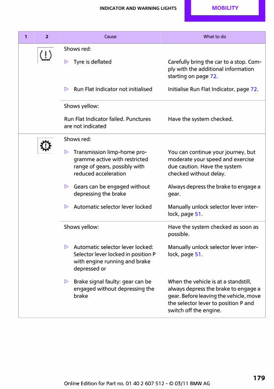
Indicator and warning lights MOBILITY
179
Shows red:
> Tyre is deflated Carefully bring the car to a stop. Com-ply with the additional information starting on page 72.
> Run Flat Indicator not initialised Initialise Run Flat Indicator, page 72.
Shows yellow:
Run Flat Indicator failed. Punctures are not indicated
Have the system checked.
Shows red:
> Transmission limp-home pro-gramme active with restricted range of gears, possibly with reduced acceleration
You can continue your journey, but moderate your speed and exercise due caution. Have the system checked without delay.
> Gears can be engaged without depressing the brake
Always depress the brake to engage a gear.
> Automatic selector lever locked Manually unlock selector lever inter-lock, page 51.
Shows yellow: Have the system checked as soon as possible.
> Automatic selector lever locked: Selector lever locked in position P with engine running and brake depressed or
Manually unlock selector lever inter-lock, page 51.
> Brake signal faulty: gear can be engaged without depressing the brake
When the vehicle is at a standstill, always depress the brake to engage a gear. Before leaving the vehicle, move the selector lever to position P and switch off the engine.
1 2 Cause What to do
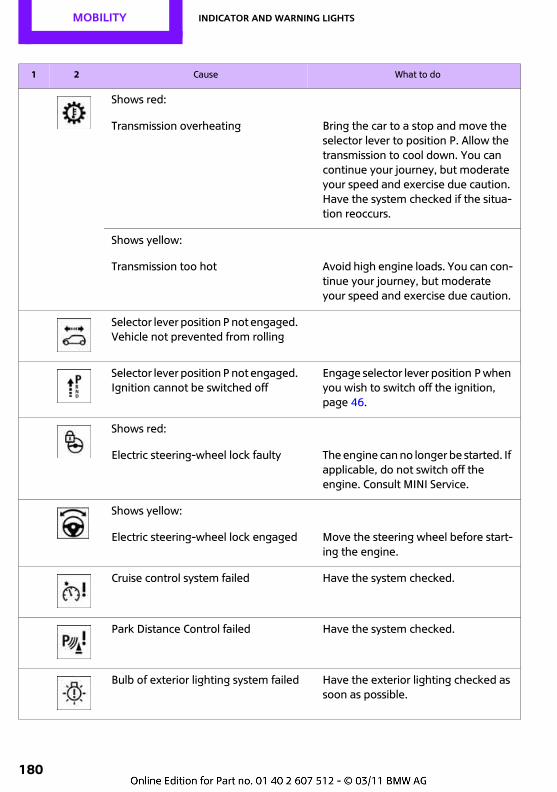
MOBILITY Indicator and warning lights
180
Shows red:
Transmission overheating Bring the car to a stop and move the selector lever to position P. Allow the transmission to cool down. You can continue your journey, but moderate your speed and exercise due caution. Have the system checked if the situa-tion reoccurs.
Shows yellow:
Transmission too hot Avoid high engine loads. You can con-tinue your journey, but moderate your speed and exercise due caution.
Selector lever position P not engaged. Vehicle not prevented from rolling
Selector lever position P not engaged. Ignition cannot be switched off
Engage selector lever position P when you wish to switch off the ignition, page 46.
Shows red:
Electric steering-wheel lock faulty The engine can no longer be started. If applicable, do not switch off the engine. Consult MINI Service.
Shows yellow:
Electric steering-wheel lock engaged Move the steering wheel before start-ing the engine.
Cruise control system failed Have the system checked.
Park Distance Control failed Have the system checked.
Bulb of exterior lighting system failed Have the exterior lighting checked as soon as possible.
1 2 Cause What to do
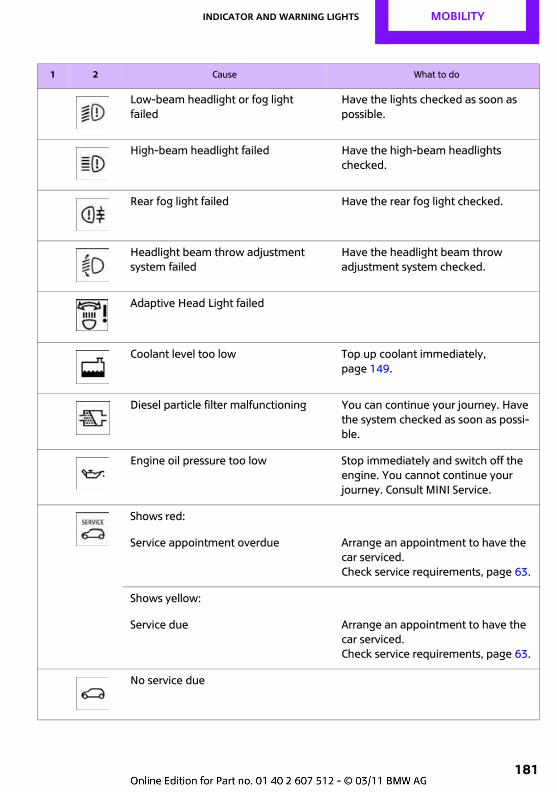
Indicator and warning lights MOBILITY
181
Low-beam headlight or fog light failed
Have the lights checked as soon as possible.
High-beam headlight failed Have the high-beam headlights checked.
Rear fog light failed Have the rear fog light checked.
Headlight beam throw adjustment system failed
Have the headlight beam throw adjustment system checked.
Adaptive Head Light failed
Coolant level too low Top up coolant immediately, page 149.
Diesel particle filter malfunctioning You can continue your journey. Have the system checked as soon as possi-ble.
Engine oil pressure too low Stop immediately and switch off the engine. You cannot continue your journey. Consult MINI Service.
Shows red:
Service appointment overdue Arrange an appointment to have the car serviced.Check service requirements, page 63.
Shows yellow:
Service due Arrange an appointment to have the car serviced.Check service requirements, page 63.
No service due
1 2 Cause What to do
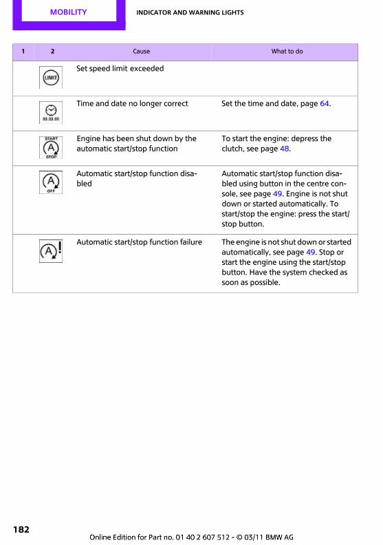
MOBILITY Indicator and warning lights
182
Set speed limit exceeded
Time and date no longer correct Set the time and date, page 64.
Engine has been shut down by the automatic start/stop function
To start the engine: depress the clutch, see page 48.
Automatic start/stop function disa-bled
Automatic start/stop function disa-bled using button in the centre con-sole, see page 49. Engine is not shut down or started automatically. To start/stop the engine: press the start/stop button.
Automatic start/stop function failure The engine is not shut down or started automatically, see page 49. Stop or start the engine using the start/stop button. Have the system checked as soon as possible.
1 2 Cause What to do
Indicator and warning lights MOBILITY
183

Find Me.
OVERVIEW
CONTROLS
DRIVING HINTS
Entertainment
COMMUNICATION
MOBILITY
REFERENCE
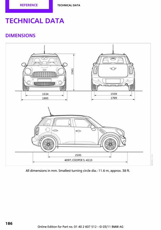
REFERENCE Technical data
186
Technical data
Dimensions
All dimensions in mm. Smallest turning circle dia.: 11.6 m, approx. 38 ft.
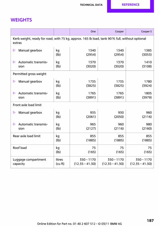
Technical data REFERENCE
187
Weights
One Cooper Cooper S
Kerb weight, ready for road, with 75 kg, approx. 165 lb load, tank 90Ξ full, without optional extras
> Manual gearbox kg (lb)
1340(2954)
1340(2954)
1385(3053)
> Automatic transmis-sion
kg (lb)
1370(3020)
1370(3020)
1410(3108)
Permitted gross weight
> Manual gearbox kg (lb)
1735(3825)
1735(3825)
1780(3924)
> Automatic transmis-sion
kg (lb)
1765(3891)
1765(3891)
1805(3979)
Front axle load limit
> Manual gearbox kg (lb)
935(2061)
930(2050)
960(2116)
> Automatic transmis-sion
kg (lb)
965(2127)
960(2116)
980(2160)
Rear axle load limit kg (lb)
855(1885)
855(1885)
855(1885)
Roof load kg (lb)
75(165)
75(165)
75(165)
Luggage compartment capacity
litres (cu ft)
350 - 1170(12.35 - 41.30)
350 - 1170(12.35 - 41.30)
350 - 1170(12.35 - 41.30)
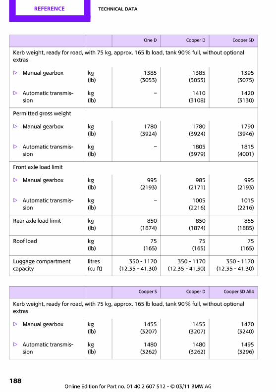
REFERENCE Technical data
188
One D Cooper D Cooper SD
Kerb weight, ready for road, with 75 kg, approx. 165 lb load, tank 90Ξ full, without optional extras
> Manual gearbox kg (lb)
1385(3053)
1385(3053)
1395(3075)
> Automatic transmis-sion
kg (lb)
– 1410(3108)
1420(3130)
Permitted gross weight
> Manual gearbox kg (lb)
1780(3924)
1780(3924)
1790(3946)
> Automatic transmis-sion
kg (lb)
– 1805(3979)
1815(4001)
Front axle load limit
> Manual gearbox kg (lb)
995(2193)
985(2171)
995(2193)
> Automatic transmis-sion
kg (lb)
– 1005(2216)
1015(2216)
Rear axle load limit kg (lb)
850(1874)
850(1874)
855(1885)
Roof load kg (lb)
75(165)
75(165)
75(165)
Luggage compartment capacity
litres (cu ft)
350 - 1170(12.35 - 41.30)
350 - 1170(12.35 - 41.30)
350 - 1170(12.35 - 41.30)
Cooper S Cooper D Cooper SD All4
Kerb weight, ready for road, with 75 kg, approx. 165 lb load, tank 90Ξ full, without optional extras
> Manual gearbox kg (lb)
1455(3207)
1455(3207)
1470(3240)
> Automatic transmis-sion
kg (lb)
1480(3262)
1480(3262)
1495(3296)
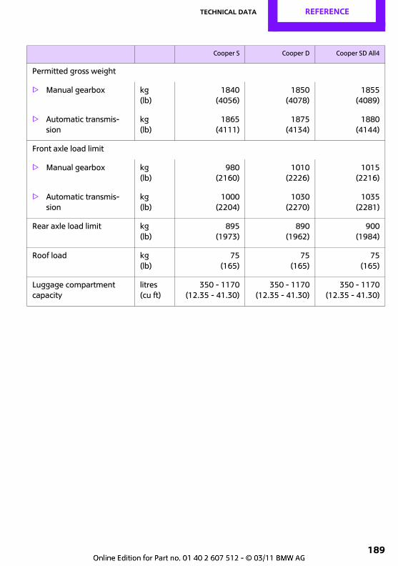
Technical data REFERENCE
189
Permitted gross weight
> Manual gearbox kg (lb)
1840(4056)
1850(4078)
1855(4089)
> Automatic transmis-sion
kg (lb)
1865(4111)
1875(4134)
1880(4144)
Front axle load limit
> Manual gearbox kg (lb)
980(2160)
1010(2226)
1015(2216)
> Automatic transmis-sion
kg (lb)
1000(2204)
1030(2270)
1035(2281)
Rear axle load limit kg (lb)
895(1973)
890(1962)
900(1984)
Roof load kg (lb)
75(165)
75(165)
75(165)
Luggage compartment capacity
litres (cu ft)
350 - 1170(12.35 - 41.30)
350 - 1170(12.35 - 41.30)
350 - 1170(12.35 - 41.30)
Cooper S Cooper D Cooper SD All4
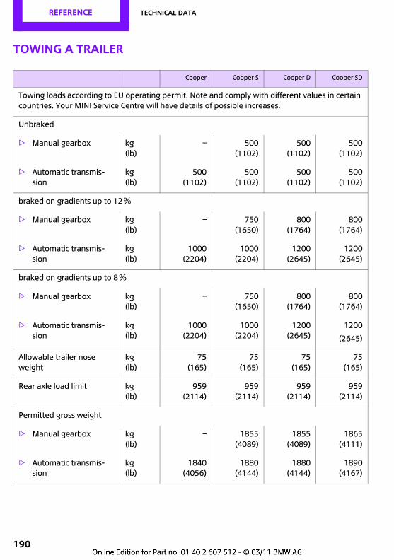
REFERENCE Technical data
190
Towing a trailer
Cooper Cooper S Cooper D Cooper SD
Towing loads according to EU operating permit. Note and comply with different values in certain countries. Your MINI Service Centre will have details of possible increases.
Unbraked
> Manual gearbox kg (lb)
– 500(1102)
500(1102)
500(1102)
> Automatic transmis-sion
kg (lb)
500(1102)
500(1102)
500(1102)
500(1102)
braked on gradients up to 12Ξ
> Manual gearbox kg (lb)
– 750(1650)
800(1764)
800(1764)
> Automatic transmis-sion
kg (lb)
1000(2204)
1000(2204)
1200(2645)
1200(2645)
braked on gradients up to 8Ξ
> Manual gearbox kg (lb)
– 750(1650)
800(1764)
800(1764)
> Automatic transmis-sion
kg (lb)
1000(2204)
1000(2204)
1200(2645)
1200
(2645)
Allowable trailer nose weight
kg (lb)
75(165)
75(165)
75(165)
75(165)
Rear axle load limit kg (lb)
959(2114)
959(2114)
959(2114)
959(2114)
Permitted gross weight
> Manual gearbox kg (lb)
– 1855(4089)
1855(4089)
1865(4111)
> Automatic transmis-sion
kg (lb)
1840(4056)
1880(4144)
1880(4144)
1890(4167)
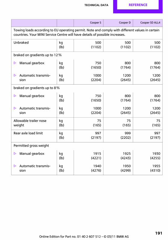
Technical data REFERENCE
191
Cooper S Cooper D Cooper SD ALL4
Towing loads according to EU operating permit. Note and comply with different values in certain countries. Your MINI Service Centre will have details of possible increases.
Unbraked kg (lb)
500(1102)
500(1102)
500(1102)
braked on gradients up to 12Ξ
> Manual gearbox kg (lb)
750(1650)
800(1764)
800(1764)
> Automatic transmis-sion
kg (lb)
1000(2204)
1200(2645)
1200(2645)
braked on gradients up to 8Ξ
> Manual gearbox kg (lb)
750(1650)
800(1764)
800(1764)
> Automatic transmis-sion
kg (lb)
1000(2204)
1200(2645)
1200(2645)
Allowable trailer nose weight
kg (lb)
75(165)
75(165)
75(165)
Rear axle load limit kg (lb)
997(2197)
999(2202)
997(2197)
Permitted gross weight
> Manual gearbox kg (lb)
1915(4221)
1925(4243)
1930(4255)
> Automatic transmis-sion
kg (lb)
1940(4276)
1950(4299)
1955(4310)
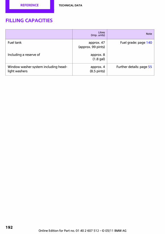
REFERENCE Technical data
192
Filling capacities
Litres(Imp. units) Note
Fuel tank approx. 47(approx. 99 pints)
Fuel grade: page 140
Including a reserve of approx. 8(1.8 gal)
Window washer system including head-light washers
approx. 4(8.5 pints)
Further details: page 55
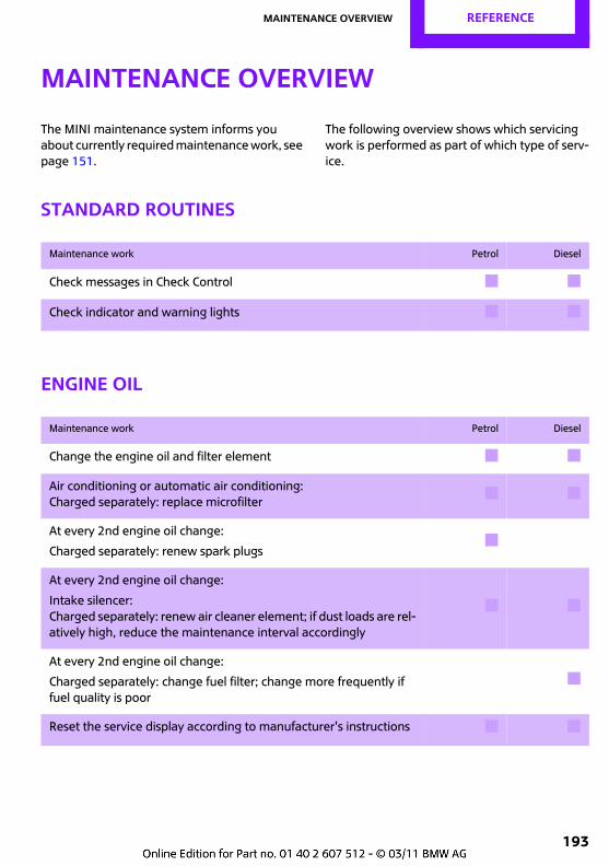
Maintenance overview REFERENCE
193
Maintenance overview
The MINI maintenance system informs you about currently required maintenance work, see page 151.
The following overview shows which servicing work is performed as part of which type of serv-ice.
Standard routines
Engine oil
Maintenance work Petrol Diesel
Check messages in Check Control # #
Check indicator and warning lights # #
Maintenance work Petrol Diesel
Change the engine oil and filter element # #
Air conditioning or automatic air conditioning:Charged separately: replace microfilter
# #
At every 2nd engine oil change:
Charged separately: renew spark plugs#
At every 2nd engine oil change:
Intake silencer: Charged separately: renew air cleaner element; if dust loads are rel-atively high, reduce the maintenance interval accordingly
# #
At every 2nd engine oil change:
Charged separately: change fuel filter; change more frequently if fuel quality is poor
#
Reset the service display according to manufacturer's instructions # #
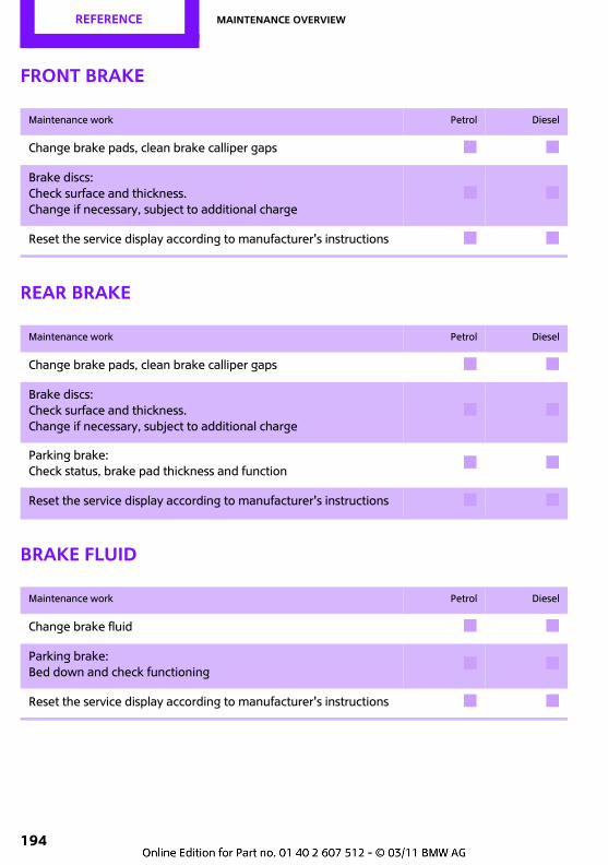
REFERENCE Maintenance overview
194
Front brake
Rear brake
Brake fluid
Maintenance work Petrol Diesel
Change brake pads, clean brake calliper gaps # #
Brake discs:Check surface and thickness.Change if necessary, subject to additional charge
# #
Reset the service display according to manufacturer's instructions # #
Maintenance work Petrol Diesel
Change brake pads, clean brake calliper gaps # #
Brake discs:Check surface and thickness.Change if necessary, subject to additional charge
# #
Parking brake:Check status, brake pad thickness and function
# #
Reset the service display according to manufacturer's instructions # #
Maintenance work Petrol Diesel
Change brake fluid # #
Parking brake: Bed down and check functioning
# #
Reset the service display according to manufacturer's instructions # #
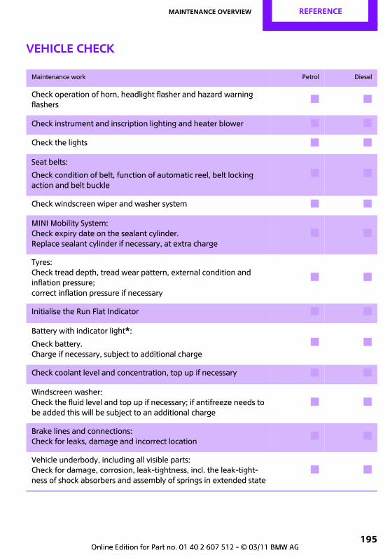
Maintenance overview REFERENCE
195
Vehicle check
Maintenance work Petrol Diesel
Check operation of horn, headlight flasher and hazard warning flashers
# #
Check instrument and inscription lighting and heater blower # #
Check the lights # #
Seat belts:
Check condition of belt, function of automatic reel, belt locking action and belt buckle
# #
Check windscreen wiper and washer system # #
MINI Mobility System: Check expiry date on the sealant cylinder.Replace sealant cylinder if necessary, at extra charge
# #
Tyres: Check tread depth, tread wear pattern, external condition and inflation pressure;correct inflation pressure if necessary
# #
Initialise the Run Flat Indicator # #
Battery with indicator light*:
Check battery. Charge if necessary, subject to additional charge
# #
Check coolant level and concentration, top up if necessary # #
Windscreen washer: Check the fluid level and top up if necessary; if antifreeze needs to be added this will be subject to an additional charge
# #
Brake lines and connections:Check for leaks, damage and incorrect location
# #
Vehicle underbody, including all visible parts:Check for damage, corrosion, leak-tightness, incl. the leak-tight-ness of shock absorbers and assembly of springs in extended state
# #
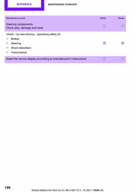
REFERENCE Maintenance overview
196
Steering components:Check play, damage and wear
# #
Check – by test-driving – operating safety of:
> Brakes
> Steering
> Shock absorbers
> Transmission
# #
Reset the service display according to manufacturer's instructions # #
Maintenance work Petrol Diesel
Maintenance overview REFERENCE
197
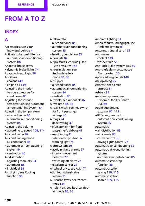
198
REFERENCE From A to Z
From A to Z
INDEX
AAccessories, see Your
individual vehicle 4Activated charcoal filter for
automatic air-conditioning system 86
Adaptive brake lights– dynamic brake lights 74Adaptive Head Light 78Additives– coolant 149– engine oil 149Adjusting the interior
temperature, see Air conditioner 83
Adjusting the interior temperature, see Automatic air-conditioning system 84
Adjusting the temperature– air conditioner 83– automatic air-conditioning
system 85Adjusting the volume– according to speed 108, 114Air conditioner 82Air conditioning mode– air conditioner 83– automatic air-conditioning
system 84– ventilation 86Air distribution– adjusting manually 84– automatic 85– individual 84Air, drying, see Cooling
function 86
Air flow rate– air conditioner 83– automatic air-conditioning
system 85– heating, ventilation 83Air outlets 82Air pressures, checking, see
Tyre pressures 142Air recirculation, see
Recirculated-air mode 83, 85
Air supply– air conditioner 83– automatic air-conditioning
system 84– ventilation 86Air vents, see Air outlets 82Air volume 83, 85Airbag switch, see Key switch
for front passenger airbags 40
Airbags 74– deactivating 40– indicator light for front
passenger's airbags 41– reactivating 41– safe seated position 32– warning light 75Alarm system 26– avoiding false alarms 27– interior movement
detector 27– switching off alarm 26– tilt alarm sensor 27All wheel drive, see ALL4 71ALL4 four-wheel drive
system 71All-season tyres, see Winter
tyres 144Ambient air, see Recirculated-
air mode 83, 85
Ambient lighting 81Ambient surrounding light, see
Ambient lighting 81Antenna, general care 153Antifreeze– coolant 149– washer fluid 55Anti-lock Brake System ABS 69Anti-theft alarm system, see
Alarm system 26Approved engine oils 149Aquaplaning 93Armrest, see Centre
armrest 87Ashtray 89Assistant systems, see– Dynamic Stability Control
DSC 69Audio equipment,
external 87, 113AUTO programme for
automatic air-conditioning system 85
Automatic– air distribution 85– air volume 85– cruise control 55– driving lights control 76Automatic air conditioning 82Automatic air-conditioning
system– automatic air distribution 85Automatic start/stop
function 48Automatic station
saving 110, 116Automatic station
search 109, 115
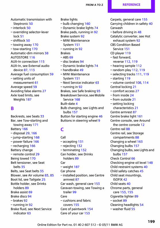
From A to Z REFERENCE
199
Automatic transmission with Steptronic 50
– interlock 50– overriding selector-lever
lock 51– shiftlock 50– towing away 170– tow-starting 170Automatic-dim mirrors 38AUTOSTORE 116AUX-In connection 115AUX-In, see External audio
device 87, 113Average fuel consumption 59– setting units of
measurement 61Average speed 59Avoiding false alarms 27Axle load limits, see
Weights 187
BBackrests, see Seats 33Bar, see Tow-starting and
towing away 171Battery 166– disposal 29, 166– jump-starting 168– power failure 166– recharging 166Battery change– remote control 29Being towed 170Belt tensioner, see Seat
belts 35Belts, see Seat belts 35Blower, see Air volume 83, 85Boot lid, see Tailgate 25Bottle holder, see Drinks
holders 89Brake assist 69Brake discs 94– brakes 92– running in 92Brake fluid, see Next Service
indicator 63
Brake lights– bulb changing 160– Dynamic brake lights 74Brake pads, running in 92Brake system 92– MINI Maintenance
System 151– running in 92Brakes– ABS 69– disc brakes 94– Dynamic brake lights 74– handbrake 49– MINI Maintenance
System 151– Next Service indicator 63– running in 92Brakes, see Safe braking 93Breakdown Service, see Mobile
Service 168Built-date 4Bulb changing, see Lights and
bulbs 157Button for starting engine 46Buttons in steering wheel 9
CCall– accepting 131– rejecting 132– terminating 132Can holder, see Drinks
holders 89Car– weight 187Car phone– installed position, see Centre
armrest 87Car wash, general care 153Caravan-towing, see Towing a
trailer 99Care– cushions and fabric
covers 155Care of paintwork 154Care of your car 153
Carpets, general care 155Carrying children in safety 40Carwash– before driving in 48Catalytic converter, see Hot
exhaust system 92CBS Condition Based
Service 151CD player 119– fast forward,
reverse 112, 119– hearing sample 112– random play 112, 119– selecting tracks 111, 119– starting 119– volume control 108, 114Central locking 21– comfort access 27– from inside 24– from outside 21– setting locking
characteristics 21Centre armrest 87Centre brake light 161Centre console, see Around
the centre console 12Centre rail 88Centre rail, see Storage
compartments 88Changing a wheel 163Changing bulbs 157Changing bulbs, see Lights and
bulbs 157Check Control 66Checking engine oil level 148Child restraint systems 40Child safety catches 45Child seat mountings,
ISOFIX 42Child seats 40Chrome parts, general
care 153, 155Cigarette lighter 89– socket 89Cleaning headlights 54– washer fluid 55
REFERENCE From A to Z
200
Clearance warning, see Park Distance Control PDC 68
Clock– setting 115– setting time 64– 12-hour/24-hour mode 61Closing– from inside 24Clutch, running in 92Coat hooks 88Cold start, see Starting the
engine 47Comfort access 27– changing the battery 29Comfort operation– windows 22Comfort/convenience, see
Around the centre console 12
Compartment for remote control, see Ignition lock 46
Compressed audio file 111Compressed audio files 119Computer 59Condensation, see Car
parked 94Configuring settings, see
Personal Profile 20Confirmation signals for
locking/unlocking the vehicle 22
Connecting vacuum cleaner, see Connecting electrical appliances 89
Consumption display– average consumption 59Consumption display, see Fuel
gauge 58Consumption, see Average
fuel consumption 59Controls and displays 8Convenient access– in an automatic car wash 28Convenient starting, see
Starting the engine 47
Coolant 149– checking level 150– temperature 150– topping up 150Coolant temperature 150Cooling fluid, see Coolant 149Cooling, maximum 85Copyright 2Cornering lights, see Adaptive
Head Light 78Cup holder, see Drinks
holders 89Current fuel consumption 59
DDashboard lighting, see
Instrument lighting 80Dashboard, see Displays 10Data– dimensions 186– filling capacities 192– weights 187Data memory 152Date– setting 65Date setting 115Daytime running lights 77DBC Dynamic Brake Control,
see Brake assist 69Deactivating/activating
Bluetooth connection 128Deadlocking, see Locking 22Defect– tyres 73Defogging windows 84, 85Defrost setting 84, 85Defrosting windows and
removing mist 84, 85– air conditioner 84– automatic air-conditioning
system 85Diesel particle filter 93Digital radio 117Dimensions 186Dipstick, engine oil 148
Display lighting, see Instrument lighting 80
Displays 10– instrument cluster 10Displays and controls 8Displays, care 156Disposal– battery for remote control 29– of coolant 149– vehicle battery 166Distance remaining to service,
see Next Service indicator 63Door key, see Key/remote
control 20Door locking, confirmation
signals 22Door locks 23Doors, manual operation 24Downhill gradients 94Drinks holders 89Drive-off assistant, see– DSC 69– Hill Start Assist 71Driving area 8Driving dynamics control, see
Sport button 71Driving hints 92Driving lights control,
automatic 76Driving lights, see Side lights/
low-beam headlights 76Driving on left 94Driving stability control
systems 69Dry air, see Cooling
function 86DSC Dynamic Stability
Control 69DTC Dynamic Traction
Control 70DTMF suffix dialling 132Dynamic Brake Control DBC,
see Brake assist 69Dynamic brake lights 74Dynamic Stability Control
DSC 69
From A to Z REFERENCE
201
Dynamic Traction Control DTC 70
EEBV Electronic Brake Force
Distribution 69Eject button 112, 120Electric windows 30Electric windows, see
Windows 30Electrical fault– door lock 24– fuel filler flap 140Electronic Brake Force
Distribution 69Electronic Stabilisation
Program ESP, see Dynamic Stability Control DSC 69
Emergency operation, see Manual operation
– door lock 24– fuel filler flap 140– transmission lock, automatic
transmission 51Emergency Service, see Mobile
Service 168Engine– overheated, see Coolant
temperature 150– running in 92– starting 47– starting, convenient
access 27– stopping 47Engine compartment 147Engine compartment lid 146Engine coolant, see
Coolant 149
Engine oil– adding 149– additives, see Approved
engine oils 149– alternative oil grades 149– approved engine oils 149– checking level 148– dipstick 148– filling capacity 149– intervals between changes,
see Next Service indicator 63– MINI Maintenance
System 151Engine starting, see Starting
the engine 47Error messages, see Check
Control 66ESP Electronic Stabilisation
Program, see Dynamic Stability Control DSC 69
Exhaust system, see Hot exhaust system 92
Expanding the luggage area 95
Exterior mirror– automatic dimming 38Exterior mirrors 37– automatic heating 38– folding in and out 38– towing a trailer 101External audio
equipment 87, 113, 115Eyes– for lashing loads 98– for tow-starting and towing
away 170
F
Failure message, see Check Control 66
Failure of an electrical consumer 166
False alarms, avoiding 27Fasten seat belts, see Seat
belts 35
Fault– door lock 24– fuel filler flap 140Fault messages, see Check
Control 66Filling capacities 192Filter– micro-filter for air
conditioner 84– micro-filter/activated
charcoal filter for automatic air-conditioning system 86
Fine wood, general care 156First aid pouch 168Fixture for remote control, see
Ignition lock 46Flashing turn indicators 52– front, changing 159– indicator light 10– rear, bulb changing 160– side, bulb changing 160Flashing when locking/
unlocking 22Flat tyre– indicator/warning light 73– MINI Mobility System 161– run-flat tyres 73Flat tyre, see Condition of
tyres 142Floods, see Wading 93Fog lights 79– bulb changing 159– indicator light 172Folding rear-seat backrests 95Foot mats, general care 155Footbrake, see Safe braking 93Footwell lights 80For floor panel, see Flat
luggage compartment floor 96
For your own safety 5Forward– CD 119Forward CD 112Four-wheel drive, see ALL4 71Front airbags 74Front fog lights 79
REFERENCE From A to Z
202
Front passenger airbags– deactivating 40– reactivating 41Front seat adjustment 33Frost protection– coolant 149– washer fluid 55Fuel 140– fuel gauge 58– grade 140– see Average fuel
consumption 59– see Fuel grade 140– tank content 192Fuel filler flap 140– unlocking in the event of an
electrical fault 140Fuel level 58Fuses 166
GGear indicator– automatic transmission with
Steptronic 50Gearshift lever– automatic transmission with
Steptronic 50– manual gearbox 49Gearshift point display 59Gearshifts– with automatic
transmission 50– with manual gearbox 49General care 153– care products 153– CD/DVD drives 156– exterior 153– high pressure cleaning
jets 154– interior 155– leather 155– vehicle washes 153– washing by hand 154– windows 154General driving notes 92
Glass roof, electric– convenient operation 22, 24– opening, closing 29– raising 29– remote control 22Glass sunroof, electric 29Glove compartment 87Gong– volume 108, 114Grilles, see Air outlets 82Gross weight, see Weights 187
HHalogen headlights– bulb changing 158– driving on left/right 94– manual headlight beam
throw adjustment 78Handbrake 49Hands-free unit 12, 134Hazard warning flashers 12Head restraints 34– safe seated position 32Head-level airbag 74Headlight– beam throw adjustment 78Headlight adjustment, see
Rule of the road 94Headlight beam throw
adjustment 78– automatic for xenon
headlights 79Headlight courtesy delay
feature 76Headlight flasher 52– indicator light 9, 172Headlight lenses 158Headlights– bulb changing 158Headlights, general care 154Hearing sample Scan– CD 112– Radio MINI Boost CD 116
Heating 82– mirrors 38– rear window 83, 85– seats 35Heavy loads, see Loading 98Height adjustment– seats 33– steering wheel 38Height, see Dimensions 186High-beam headlights 79– bulb changing 158– headlight flasher 79– indicator light 172Hill Start Assist 71Hinged rear-seat backrests 95Hints for driving, see Driving
hints 92Holder for drinks 89Holder for telephone or mobile– phone, see Snap-in
adapter 136Homepage 4Horn 8Hot exhaust system 92
IIce warning, see Outside
temperature warning 59Icy roads, see Outside
temperature warning 59Ignition 46– switched off 47– switched on 46Ignition key position 1, see
Radio readiness 46Ignition key position 2, see
Ignition on 46Ignition key, see Key/remote
control 20Ignition lock 46Imprint 2Incoming call 131Indicator and warning
lights 11, 172Indicators, see Flashing turn
indicators 52
From A to Z REFERENCE
203
Individual air distribution 84Individual settings, see
Personal Profile 20Inflation pressure monitoring,
see Run Flat Indicator 72Inflation pressure, tyres 142Initialising– glass roof, electric 30– Run Flat Indicator RPA 72Instrument cluster, see
Displays 10Instrument lighting 80Instrument panel, see
Cockpit 8Integrated key 20Interior light 80– remote control 23Interior mirror 38– automatic-dim 38Interior movement
detector 27Interlock 50Intermittent wiper
operation 53ISOFIX child seat mountings 42
JJack– mounting points 164Jacking points 164Jump-starting, see Starting
with a flat battery 168
K
Kerb weight, see Weights 187Key Memory, see Personal
Profile 20Key switch for front passenger
airbags 40Keyless Go, see Convenient
access 27Keyless locking and unlocking,
see Comfort access 27Keys, see Key/remote
controls 20
Kick-down 51– automatic transmission with
Steptronic 51Knock control 140
L
Lap-and-shoulder seat belt 35Lashings, see Securing the
load 98Laying up out of use 156Leather care 155LEDs light-emitting diodes 157Length, see Dimensions 186Level load platform 96Licence plate light– bulb replacement 161Light– automatic driving lights
control 76Light switch 76Light-emitting diodes
LEDs 157Lighter 89Lighting– instruments 80– lights and bulbs 157– vehicle, see Lights 76Light-metal alloy wheels,
general care 155Lights and bulbs, bulb
change 157Lights, see Side lights/low-
beam headlights 76Limit 182Loads– loading 98– securing 98– trailer 101– vehicle 95Load-securing equipment, see
Securing the load 98Lockable wheel studs, see
Thief-proof wheel studs 165
Locking– adjusting confirmation
signal 22– from inside 24– from outside 21, 22– without remote control, see
Convenient access 27Longlife oils– alternative oil grades 149– approved engine oils 149Low fuel level warning light 58Low-beam headlights 76– automatic 76– bulb changing 158Luggage area 95– convenient access 28– light 80Luggage compartment– doors, see Tailgate 25– lid, see Tailgate 25– opening from outside 25– volume 187Luggage compartment
partition net, see Partition net 97
Luggage rack, see Roof rack 99
Luggage-area light 80Lumbar support 34
MM+S tyres, see Winter
tyres 144Maintenance, see Service
BookletMaintenance system 151Manual air distribution 84Manual gearbox 49Manual operation– automatic transmission with
Steptronic 51– door lock 24– fuel filler flap 140– transmission interlock,
automatic transmission 51
REFERENCE From A to Z
204
Manual station search 109, 116
Master key, see Key/remote control 20
Maximum cooling effect 85Measurements, see
Dimensions 186Micro-filter– for air conditioner 84– for automatic air-
conditioning system 86– MINI Maintenance
System 151Micro-filter/activated charcoal
filter– MINI Maintenance
System 151Microphone for telephone 12MINI Maintenance System 151MINI website 4Minimum volume 108, 114Mirrors 37– exterior mirrors 37– heating 38– inside mirror 38Mobile phone– adjusting volume 131– connecting, see Pairing a
mobile phone 128– installed position, see Centre
armrest 87– pairing 128– what to do if... 130Mobile phone, installed
position, see Centre armrest 87
Mobile Service 168Mobility System 161Modifications, technical, see
For your own safety 5MP3 111, 119Multi-function lever– see Flashing turn indicators/
headlight flasher 52Multifunction switch– see Wiper system 53
Multifunctional steering wheel, see Buttons on the steering wheel 9
Music track– hearing sample 112– random sequence 112, 119
NNeck restraints, see Head
restraints 34Nets, see Storage
compartments 88New tyres 143Next Service indicator, see
Condition Based Service CBS 151
Nose weight 101, 190Nozzles, see Air outlets 82Nozzles, see Ventilation 86Number of seat belts 32Nylon rope, see Towrope 171
OOBD socket, see Socket for on-
board diagnosis 152Octane numbers, see Fuel
grade 140Odometer 58Oil consumption 148Oil grades 149Oil level 148Oil, see Engine oil 148Old batteries, see Disposal 166Opening and closing– convenient access 27– from inside 24– from the outside 21– via the door lock 23– via the remote control 21Opening and unlocking– from the inside 24Opening, see Unlocking 28Outlets– see Ventilation 86
Outside mirrors– adjusting 37Outside temperature display– changing units of
measure 61– in computer 61Outside temperature
warning 59Outside-air mode– automatic air-conditioning
system 85Overheated engine, see
Coolant temperature 150
PPaint, general care 154Park Distance Control PDC 68Parking aid, see Park Distance
Control PDC 68Parking brake, see
Handbrake 49Parking lights 79– bulb changing 159Particle filter, see Diesel
particle filter 93Partition net 97Parts and accessories, see Your
individual vehicle 4PDC– volume 108, 114PDC Park Distance Control 68Personal Profile 20Petrol, see Fuel grade 140phone 126Phone call– ending 132Phone number– dialling 132Placing a call, see Dialling a
phone number 132Plasters, see First aid
pouch 168Plastic parts, general care 156
From A to Z REFERENCE
205
Pollen– see Micro-filter for air
conditioner 84– see Micro-filter/activated
charcoal filter for automatic air-conditioning system 86
Power failure 166Preheating, see Cars with
diesel engine 47Pressure monitoring, tyres 72– Run Flat Indicator 72Pressure, tyres 142Programme type 111Protective function, see Trap
protection– windows 31PTY 117Pull-away assistant, see Hill
Start Assist 71Puncture– Run Flat Indicator 72Punctures– run-flat tyres 143
RRadio 109Radio MINI Boost CD– Autostore 116– digital radio 117– retrieving station 116– saving station 116– scanning station 116– search for station 115– setting tone 115– switching on/off 114– volume 114Radio MINI CD– recalling a station 110– sampling a station 110– searching for station 109– setting tone 109– switching on/off 108– volume 108Radio position, see Radio
readiness 46
Radio readiness 46– switched off 47– switched on 46Radio-control key, see Key/
remote control 20Rain sensor 53Range 59RDS 111, 117Reading lights 80Rear fog light 79– indicator light 172Rear lights 160– bulb changing 160Rear luggage rack 99Rear seats– adjusting 34– folding backrests 95Rear window– window wiper 55Rear window heating 83, 85Rear-seat backrests,
hinged 95Rear-view mirror, see
Mirrors 37Reception– quality 117– radio stations 109, 115– regional
programme 111, 117Recirculated-air mode 83, 85Recirculation of air, see
Recirculated-air mode 83, 85
Reclining seat, see Seat back 33
Recycling 152Refuelling 140Regional programme 117Releasing– engine compartment lid 146Remote control 20– changing the battery 29– comfort access 27– faults 23, 28– service data 151– tailgate 23
Remote control, replacement 20
Reserve warning, see Fuel gauge 58
Reservoir for washer fluid 55Reset, see Resetting the tone
settings 109, 115RESET? 108Residual distance, see
Range 59Restraint systems– for children 40– see Seat belts 35Returning end-of-life vehicles,
see Recycling 152Reverse– CD 119Reverse CD 112Reverse gear– automatic transmission with
Steptronic 50– manual gearbox 50Reversing lights– bulb changing 160Revolution counter 58Roadworthiness test, see Next
Service indicator 63RON, see Fuel grade 140Roof load 187Roof rack 99Rope, see Tow-starting and
towing away 171RPA, see Run Flat Indicator 72RSC Runflat System
Component, see Run-flat tyres 143
Rubber parts, general care 154Rule of the road, headlight
adjustment 94Run Flat Indicator RPA 72– indicating a flat tyre 73– initialising the system 72– snow chains 72– system limits 72Runflat System Component
RSC, see Run-flat tyres 143
REFERENCE From A to Z
206
Run-flat tyres 143– flat tyre 73– replacing tyres 143– tyre pressure 142– winter tyres 144RunFlat Tyres, see Run-flat
tyres 143Running in the final drive 92Running in 92
SSafe seated position 32– airbags 32– seat belts 32– with head restraints 32Safety lock buttons on doors,
see Locking 24Safety switch for back seat
windows 31Safety system– driving stability control
systems 69Safety systems– airbags 74– Anti-lock Brake System
ABS 69– Dynamic Stability Control
DSC 69– seat belts 35Safety tyres, see Run-flat
tyres 143Saving energy– gearshift point display 59Scan, hearing a sample– Radio MINI CD 110Scan, hearing sample– CD player 112– Radio MINI Boost CD 116Scanning tracks Scan– CD 119Screw thread for towing
eye 170Search– CD player 111, 119– radio 115
Search run– Radio MINI CD 109Search track– CD 119Search track CD 111Seat adjustment– mechanical 33– rear 34Seat belt reminder, see 'Fasten
seat belts' reminder 37Seat belts 35– 'Fasten seat belts'
reminder 37– damage 37– indicator light 37– number of 32– rear centre seat belt 36– safe seated position 32Seat belts, general care 156Seats 33– adjusting 33– heating 35– safe seated position 32Securing the load 98Securing the load, see
Loads 98Securing, vehicle– from inside 24– from outside 21Selector lever– automatic transmission with
Steptronic 50Selector lever lock– automatic transmission with
Steptronic, see Shiftlock 50– overriding manually 51Selector lever positions– automatic transmission with
Steptronic 50Service 151Service data in the remote
control 151Service Interval indicator, see
Condition Based Service CBS 151
Service requirements 63
Service, see Mobile Service 168
Service vehicle, see Mobile Service 168
Setting time format 115Settings– clock, 12-hour/24-hour
mode 61Settings and information 60Shift paddles 51Shifting gears– automatic transmission with
Steptronic 51– manual gearbox 49Shiftlock– automatic transmission, see
Changing selector lever positions 50
Side airbags 74Side flashing turn indicators– bulb changing 160Side lights, bulb changing 159Side lights/low-beam
headlights 76Side windows, see Windows 30Signal horn, see Horn 8Slot for remote control 46Smokers' package, see
Ashtray 89Snap-in adapter– inserting/removing 136– use 126Snap-in adapter, see Centre
armrest storage compartment 87
Snow chains 145Socket for on-board diagnosis
OBD 152Socket, see Connecting
electrical appliances 89Soot particle filter, see Diesel
particle filter 93Sound– middle setting 109, 115Special oils, see Approved
engine oils 149
From A to Z REFERENCE
207
Speed– when towing a trailer 102Speed limit– with winter tyres 144Speedometer 10Speed-related
volume 108, 114Split rear-seat backrests, see
Expanding the luggage area 95
Sport button 71Sport programme– automatic transmission with
Steptronic 51Stability control, see Driving
stability control systems 69Start/stop button 46– starting the engine 47– switching off the engine 47Starting on uphill gradients,
see Hill Start Assist 71Starting the engine– start/stop button 46Starting with a flat battery 168Station, see Radio MINI Boost
CD 116Station, see Radio MINI CD 110Status at time of printing 5Steering wheel 38– adjusting 38– buttons on the steering
wheel 9– lock 46– shift paddles 51Steptronic, see Automatic
transmission with Steptronic 50
Stop light, see Rear lights 160– bulb changing 160Stopping– engine 47– vehicle 47Storage compartments 88Storage space– luggage area 95– storage compartments 88Storing tyres 144
Stowage, see Storage compartments 88
Summer tyres, see Wheels and tyres 142
Sun roof– see Glass roof, electric 29Switch for front passenger
airbags 40Switches, see Driving area 8Switching cooling function on
and off 86Switching off the engine– start/stop button 46Switching on/off– CD player 108, 114, 119– Radio MINI Boost CD 114– Radio MINI CD 108Symbols 4
TTail lights, see Rear lights 160Tailgate 25– convenient access 28– opening from outside 25– opening/closing 25– unlocking with the remote
control 23Tank capacity, see Filling
capacities 192Technical data 186Technical modifications 5Telephone– hands-free unit 134– installed position, see Centre
armrest 87– voice input 134Temperature display– setting unit of
measurement 61Temperature of the coolant,
see Coolant temperature 150
Tempomat, see Cruise control 55
Tensioning straps, see Securing the load 98
Theft protection– for wheel studs, see
Thief-proof wheel studs 165Thief-proof wheel studs 165Third brake light, see Centre
brake light 161Tightening torque, see
Tightening the wheel studs 165
Tilt alarm sensor 27Time 109Tone– setting 109, 115Top speed– when towing a trailer 102Torque– wheel studs 165Towbar 171Towing a trailer 99Towing away 170– cars with automatic
transmission 170– methods 171Towing eye 170– screw thread 170Towing eyes for tow-starting
and towing away 170Towrope 171Tow-starting 170TP, see Traffic reports 110, 117Track– scanning track 119Track width, see
Dimensions 186Traffic reports 110, 117– displays 117– switching on/off 117– volume control 114Trailer pulling, see Towing a
trailer 99Trailer tow hitch 99Trailer towing– towing loads and gross
weight 190
REFERENCE From A to Z
208
Transmission– automatic transmission with
Steptronic 50– manual gearbox 49– overriding selector-lever lock
for automatic transmission with Steptronic 51
Transport securing equipment, see Securing the load 98
Transporting children 40Trap protection– windows 31Tread depth, see Minimum
tread depth 142Trip distance recorder 58Triple turn signal 52Turning circle, see
Dimensions 186Tyre changing, see New
wheels and tyres 143Tyre pressure– loss 73Tyre pressure monitoring, see
Run Flat Indicator 72Tyre pressures 142Tyre puncture– Run Flat Indicator 73Tyres– age 143– changing, see Changing a
wheel 163– condition 142– damage 142, 143– minimum tread depth 142– new 143– pressure monitoring, see Run
Flat Indicator 72– pressures 142– punctures 73– run-flat tyres 143– running in 92– size 142– wear indicators, see
Minimum tread depth 143– winter tyres 144
Tyres with emergency running properties
– Run Flat Indicator 73Tyres with emergency running
properties, Run-flat tyres 143
UUnits of measurement– average fuel consumption 61– temperature 61Unlocking– from outside 21– setting unlocking
characteristics 21– tailgate 28– without remote control, see
Convenient access 27Unlocking and locking doors– confirmation signals 22– from inside 24– from outside 21Upholstery, general care 155USB audio interface 121
VVehicle– battery 166– dimensions 186– Identification Number, see
Engine compartment 147– laying up out of use 156– loads 95– returning, see Recycling 152– running in 92– stopping 47Vehicle battery, see Vehicle
battery 166Vehicle Identification Number,
see Engine compartment 147
Vehicle jack 164Vehicle key, see Key/remote
control 20
Vehicle phone, see Telephone 126
Vehicle radio, see Radio MINI Boost CD 114
Vehicle radio, see Radio MINI CD 108
Vehicle recycling, see Recycling 152
Vehicle washes 153Ventilation 86– air conditioner 86Ventilation, see Climate 82Voice input– telephone 134Voice-activated phone
book 135Volume– gong 108, 114– mobile phone 131– PDC 108, 114Volume control– traffic reports 108, 114Volume of the luggage
compartment 187
WWading 93Warning and indicator
lights 11, 172Warning messages, see Check
Control 66Warning triangle 168Washer fluid 55– reservoir capacity 55Washer fluid reservoir for
cleaning systems 55Washer jets, see Windscreen
washer jets 54Washing by hand 154Waste tray, see Ashtray 89Water on roads, see Wading 93Waterfall lighting, see Ambient
lighting 81Wear indicators in the tyres,
see Minimum tread depth 143
From A to Z REFERENCE
209
Website 4Weights 187Welcome lights 76Wheel studs– torque 165, 166Wheelbase, see
Dimensions 186Wheels and tyres 142Wheels, new 143Wheelslip control, see– Dynamic Stability Control
DSC 69Width, see Dimensions 186Window lifter– safety switch 31Window washer reservoir, see
Washer fluid 55– content, see Filling
capacities 192Window washer system 53– washer fluid 55– washer jets 54Windows 30– closing 30– comfort operation 22– opening 30– safety switch 31– trap protection 31Windscreen– cleaning 54– defrosting 84, 85Windscreen defrosting, see
Defrosting windows 84, 85Windscreen wiper blades,
changing 157Winter tyres 144– tyre storage 144Wiper blades, general care 154Wiper system 53– washer fluid 55WMA 119Working in the engine
compartment 146
XXenon headlights 79– automatic headlight beam
throw adjustment 79– bulb changing 158– driving on left/right 94
Y
Your car 4


0140
260
751
2 e
n
*BL260751200N*
DRIVE ME.