Embed Size (px)
Citation preview

81264_1.book Page 1 Monday, December 5, 2005 9:16 AM
ST60+ Wind & Close Hauled Wind InstrumentOwner’s Handbook
Document reference: 81264-1 Date: December 2005

81264_1.book Page 2 Monday, December 5, 2005 9:16 AM
Raymarine, ST60+ and SeaTalk are trademarks of Raymarine UK Limited © Handbook contents copyright Raymarine UK Limited 2005
i
81264_1.book Page i Monday, December 5, 2005 9:16 AM
ContentsContentsPreface
Important information
Safety notices
EMC conformanceAll Raymarine equipment and accessories are designed to the best industry standards for use in the recreational marine environment.
The design and manufacture of Raymarine equipment and accessories conform to the appropriate Electromagnetic Compatibility (EMC) standards, but correct installation is required to ensure that performance is not compromised.
Handbook informationTo the best of our knowledge, the information in this handbook was correct when it went to press. However, Raymarine cannot accept liability for any inaccuracies or omissions it may contain.
In addition, our policy of continuous product improvement may change specifications without notice. Therefore, Raymarine cannot accept liability for any differences between the product and the handbook.
WARNING: Product installation & operationThis equipment must be installed and operated in accordance with the Raymarine instructions provided. Failure to do so could result in personal injury, damage to your boat and/or poor product performance.
WARNING: Electrical safetyMake sure you have switched off the power supply before you start installing this product.
WARNING: Navigational safetyAlthough we have designed this product to be accurate and reliable, many factors can affect its performance. Therefore, it should serve only as an aid to navigation and should never replace commonsense and navigational judgement. Always maintain a permanent watch so you can respond to situations as they develop.

ii ST60+ Wind & Close Hauled Wind Instrument Owner’s Handbook
81264_1.book Page ii Monday, December 5, 2005 9:16 AM
Product disposalWaste Electrical and Electronic (WEEE) DirectiveThe WEEE Directive requires the recycling of waste electrical and electronic equipment.
Whilst the WEEE Directive does not apply to some of Raymarine's products, we support its policy and ask you to be aware of how to dispose of this product.
The crossed out wheelie bin symbol, illustrated above, and found on our products signifies that this product should not be disposed of in general waste or landfill.
Please contact your local dealer, national distributor or Raymarine Technical Services for information on product disposal.
Preface iii
81264_1.book Page iii Monday, December 5, 2005 9:16 AM
Preface
ContentsPreface ................................................................................................................................ i
Important information ............................................................................................ iWARNING: Product installation & operation.......................................... iWARNING: Electrical safety .......................................................................... iWARNING: Navigational safety ................................................................... i
EMC conformance ............................................................................................. iHandbook information ...................................................................................... i
Product disposal ..................................................................................................... iiContents........................................................................................................... iiiIntroduction ..........................................................................................................vii
ST60+ Wind.....................................................................................................viiST60+ Close Hauled Wind ..............................................................................viii
Data inputs ...........................................................................................................viiiSeaTalk ...........................................................................................................viiiStand alone operation ....................................................................................viii
Remote control ....................................................................................................viiiMounting options ................................................................................................. ixParts supplied ........................................................................................................ ix
Chapter 1: Operation ..................................................................................................... 11.1 Getting started ................................................................................................. 1WARNING: Calibration requirement ......................................................... 1
Switching on and off......................................................................................... 1Calibration alert................................................................................................ 1Displayed information ...................................................................................... 2
Pointer ..................................................................................................... 2Digital display .......................................................................................... 2
1.2 Normal operation ............................................................................................. 2True/Apparent button ....................................................................................... 4VMG button...................................................................................................... 4Tack button....................................................................................................... 4Alarms .............................................................................................................. 4
Canceling an alarm .................................................................................. 4Setting alarm conditions .......................................................................... 5
1.3 Display illumination ......................................................................................... 61.4 Remote control ................................................................................................ 6
Chapter 2: Maintenance & Troubleshooting .......................................................... 72.1 Maintenance .................................................................................................... 7
Servicing and safety.......................................................................................... 7Instrument........................................................................................................ 7

iv ST60+ Wind & Close Hauled Wind Instrument Owner’s Handbook
81264_1.book Page iv Monday, December 5, 2005 9:16 AM
Transducer.........................................................................................................7Cabling..............................................................................................................8
2.2 Troubleshooting ...............................................................................................8Preliminary procedures .....................................................................................8Fixing faults.......................................................................................................8Technical support ..............................................................................................8
World wide web....................................................................................... 9Telephone help line.................................................................................. 9Help us to help you .................................................................................. 9
Chapter 3: Installation ................................................................................................113.1 Planning your installation ...............................................................................11
Site requirements............................................................................................11Transducers............................................................................................ 11Instrument.............................................................................................. 12
CAUTION: Keep the rear of the instrument dry ..................................13EMC installation guidelines.............................................................................13
Suppression Ferrites ............................................................................... 143.2 Procedure .......................................................................................................14CAUTION: Maintain structural safety .....................................................14
Unpacking.......................................................................................................14Fitting the 1instruments ..................................................................................15
Surface mounting................................................................................... 15Flush mounting ...................................................................................... 16
CAUTION: Use the correct screws.............................................................17Bracket Mounting .................................................................................. 19
Fitting transducers ..........................................................................................19Typical wind vane installation................................................................ 19Rotavecta ............................................................................................... 21Running transducer cable....................................................................... 22
Connecting the instruments............................................................................24Types of connection ............................................................................... 24Signal connections ................................................................................. 24Power supply connections...................................................................... 25
CAUTION: Protect the power supply.......................................................253.3 Switching on ..................................................................................................27WARNING: Calibration requirement .......................................................27
EMC conformance...........................................................................................27

Preface v
81264_1.book Page v Monday, December 5, 2005 9:16 AM
Chapter 4: Calibration ................................................................................................. 294.1 Introduction ................................................................................................... 294.2 User calibration .............................................................................................. 29
Linearizing and aligning the wind transducer ................................................. 29Leaving User calibration ................................................................................. 30
4.3 Intermediate calibration ................................................................................ 30Leaving Intermediate calibration.................................................................... 31
4.4 Dealer calibration ........................................................................................... 31User calibration on/off .................................................................................... 33Response settings........................................................................................... 33Wind speed..................................................................................................... 34Boat show mode............................................................................................. 34
CAUTION: Do NOT enable Boat Show Mode ........................................ 34Factory defaults .............................................................................................. 34Leaving Dealer calibration .............................................................................. 34
Glossary ........................................................................................................................... 35
Index ................................................................................................................................. 37

vi ST60+ Wind & Close Hauled Wind Instrument Owner’s Handbook
81264_1.book Page vi Monday, December 5, 2005 9:16 AM

Preface vii
81264_1.book Page vii Monday, December 5, 2005 9:16 AM
PrefaceIntroductionThank you for purchasing a Raymarine product. We are sure your ST60+ instrument will give you many years of trouble-free operation.
This handbook describes how to install and use the Raymarine ST60+ Wind and ST60+ Close Hauled Wind instruments. These give:• True and Apparent wind direction and speed. Wind speed is displayed either
in knots, meters per second or as Beaufort scale values.• Velocity made good (VMG).• Maximum wind speed.
In addition to this, ST60+ Wind master instruments give:• Maximum minimum true wind speed alarms.• High and low apparent wind angle alarms.
The ST60+ Wind and Close Hauled Wind instruments are constructed in rugged weather proofed cases. Each provides a sensitive and stable, combined analog and digital display, to deliver accurate information under even the most demanding conditions.
ST60+ WindThe ST60+ Wind instrument provides a 360° apparent wind scale and can be used either as a stand-alone unit, or as part of an integrated SeaTalk instrumentation system.
ST60 Windinstrument
ST60 Close HauledWind instrument
WIND
ST60+
TRUEAPP
VMG
DISP
TACK
TRUE
APP
VMG
DISP
TACK
CH WIND
ST60+
viii ST60+ Wind & Close Hauled Wind Instrument Owner’s Handbook
81264_1.book Page viii Monday, December 5, 2005 9:16 AM
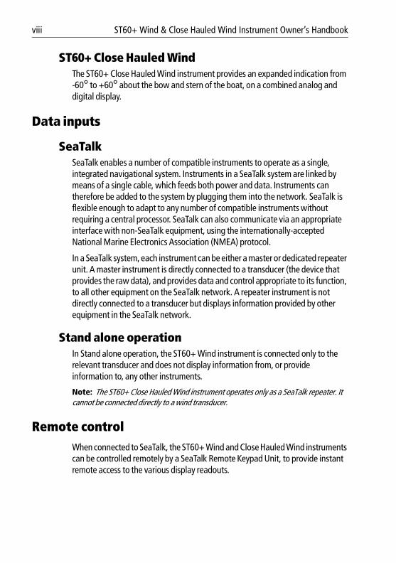
ST60+ Close Hauled WindThe ST60+ Close Hauled Wind instrument provides an expanded indication from -60° to +60° about the bow and stern of the boat, on a combined analog and digital display.
Data inputs
SeaTalkSeaTalk enables a number of compatible instruments to operate as a single, integrated navigational system. Instruments in a SeaTalk system are linked by means of a single cable, which feeds both power and data. Instruments can therefore be added to the system by plugging them into the network. SeaTalk is flexible enough to adapt to any number of compatible instruments without requiring a central processor. SeaTalk can also communicate via an appropriate interface with non-SeaTalk equipment, using the internationally-accepted National Marine Electronics Association (NMEA) protocol.
In a SeaTalk system, each instrument can be either a master or dedicated repeater unit. A master instrument is directly connected to a transducer (the device that provides the raw data), and provides data and control appropriate to its function, to all other equipment on the SeaTalk network. A repeater instrument is not directly connected to a transducer but displays information provided by other equipment in the SeaTalk network.
Stand alone operationIn Stand alone operation, the ST60+ Wind instrument is connected only to the relevant transducer and does not display information from, or provide information to, any other instruments.
Note: The ST60+ Close Hauled Wind instrument operates only as a SeaTalk repeater. It cannot be connected directly to a wind transducer.
Remote controlWhen connected to SeaTalk, the ST60+ Wind and Close Hauled Wind instruments can be controlled remotely by a SeaTalk Remote Keypad Unit, to provide instant remote access to the various display readouts.

Preface ix
81264_1.book Page ix Monday, December 5, 2005 9:16 AM
Mounting optionsA standard ST60+ instrument is surface-mounted at the required location. If you do not want to surface mount your ST60+ instrument, options are available for:• Flush mounting. If you have ordered the flush mounting option a low-profile
bezel and four fixing screws are also provided.• Bracket mounting.
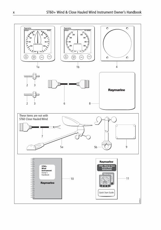
Parts suppliedUnpack your ST60+ instrument and check that the following items are present:
• EitherItem 1a, ST60+ Wind instrument, fitted with standard bezel for surface mountingorItem 1b, ST60+ Close Hauled Wind instrument, fitted with standard bezel for surface mounting.
• Item 2, Fixing studs (2).• Item 3, Thumb nuts (2).• Item 4, Gasket.• Either
Item 5a, Wind Vane (not with ST60+ Close Hauled Wind)orItem 5b, Rotavecta (not with ST60+ Close Hauled Wind).
• Item 6, SeaTalk interconnection cable.• Item 7, Power cable (not with ST60+ Close Hauled Wind).• Item 8, Instrument Cover.• Item 9, Junction Box (not with ST60+ Close Hauled Wind). • Item 10, Owner’s Handbook. A Warranty document and fitting templates are
included in this Handbook.• Item 11, Cue Card.• Spare spade terminals are also provided, to re-terminate transducer cables if
they have to be cut to facilitate installation.
Note: The above packing list is for an ST60+ Wind system. Where an instrument is pur-chased separately, a transducer and junction box are not included.
x ST60+ Wind & Close Hauled Wind Instrument Owner’s Handbook
81264_1.book Page x Monday, December 5, 2005 9:16 AM
D818
5-1
1a 1b 4
8
95b
6
These items are not with ST60 Close Hauled Wind
7
10 11
5a
ST60+ WindInstrumentOwner'sHandbook
32
32
TRUEAPP
VMGDISPTACK TRUE
APPVMGDISP
TACK
Quick Start Guide
ST60+ Wind & Close Hauled WindInstruments
disptrueapp vmg
ST60+ CH WIND
ST60+ WIND
KTS

1
81264_1.book Page 1 Monday, December 5, 2005 9:16 AM
Chapter 1: Operation
1.1 Getting startedThis handbook describes how to operate, maintain and install the Raymarine ST60+ Wind instrument and ST60+ Close Hauled Wind instrument. These instruments show:• Wind speeds and directions.• Velocity Made Good (VMG) information, when boat-speed information is
available.• Tack angle, when heading information is available.
Switching on and offAll the time that power is applied to the instrument, you can use the disp button to switch the instrument off and on as follows:• To switch the instrument off, hold down the disp button for approximately
5 seconds. After this time, a switch off count down of 4 seconds occurs. Keep the disp button pressed during this period, to switch off the instrument.
• To switch the instrument back on, hold down the disp button for approxi-mately 1 second.
When the power supply is switched off, none of the instrument buttons (including disp) has any effect.
Notes: (1) Each time power to the instrument is switched on, the instrument is ini-tially in the on condition. You do not need to use the disp button to switch the instrument on.
(2) When the instrument is on, the operation of the disp button will perform other operating functions, as described below.
Calibration alertIf the CAL legend on the digital display flashes for the first 30 seconds after any power up, use the appropriate procedures in Chapter 4, Calibration to:1. Apply the factory defaults.2. Carry out the linearization procedure.
WARNING: Calibration requirementTo ensure these products perform at their best on your boat, you MUST calibrate them before use, in accordance with the instructions in Chapter 4, Calibration. Do NOT use either product until you have successfully calibrated it.

2 ST60+ Wind & Close Hauled Wind Instrument Owner’s Handbook
81264_1.book Page 2 Monday, December 5, 2005 9:16 AM
Displayed informationThe information on the ST60+ Wind and ST60+ Close Hauled Wind instruments is presented by means of a pointer and a digital display. This information can be either true or apparent, depending on which mode is selected.
PointerThe pointer shows the true or apparent wind direction. The scale range given by the ST60+ Wind instrument is a full 360°, whereas the ST60+ Close Hauled Wind instrument gives an expanded indication from -60° to +60° about the bow or stern of the boat.
Digital displayThe digital display shows the following wind and speed information:• True/apparent wind speed.• Velocity made good (VMG).• Tack heading.• Maximum wind speed.• Wind alarm data.
You can select which information is displayed. When power is first switched on, the digital display shows the same type of information as was selected when power was last turned off.
Note: The TRUE and APP indicators flash for 8 seconds after power is switched on. This is a function of the remote control system and can be ignored if remote control is not being used.
1.2 Normal operation
TACK
TRUE APP
TRUE APP
VMG
KTS
Tack heading
Velocity made good
Press to toggle between True &Apparent indications on ST60+ Wind
Refer to the flow chartUsing the disp button
Basic operation D818
6-1
Chapter 1: Operation 3
81264_1.book Page 3 Monday, December 5, 2005 9:16 AM
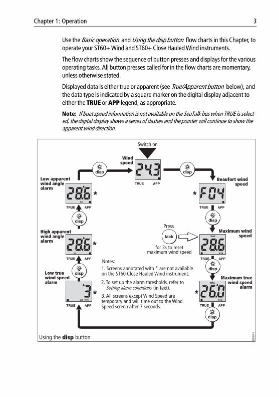
Use the Basic operation and Using the disp button flow charts in this Chapter, to operate your ST60+ Wind and ST60+ Close Hauled Wind instruments.
The flow charts show the sequence of button presses and displays for the various operating tasks. All button presses called for in the flow charts are momentary, unless otherwise stated.
Displayed data is either true or apparent (see True/Apparent button below), and the data type is indicated by a square marker on the digital display adjacent to either the TRUE or APP legend, as appropriate.
Note: If boat speed information is not available on the SeaTalk bus when TRUE is select-ed, the digital display shows a series of dashes and the pointer will continue to show the apparent wind direction.
Wind speed
Press
for 3s to resetmaximum wind speed
Using the disp button
Setting alarm conditions (in text).
Notes:
3. All screens except Wind Speed aretemporary and will time out to the WindSpeed screen after 7 seconds.
HI
LO
disp
LO KTS KTS
KTS
dispdisp
disp
disp
dispdisp
disp
1. Screens annotated with * are not availableon the ST60 Close Hauled Wind instrument.
Low apparent wind angle alarm
High apparent wind angle alarm
Low true wind speed alarm 2. To set up the alarm thresholds, refer to
Beaufort wind speed
Maximum wind speed
Maximum true wind speed
alarm
tack
Switch on
D818
7-1
4 ST60+ Wind & Close Hauled Wind Instrument Owner’s Handbook
81264_1.book Page 4 Monday, December 5, 2005 9:16 AM
True/Apparent buttonPress the true/app button to toggle between true and apparent instrument readings.
VMG buttonPress the vmg button to show VMG information on the digital display. The pointer continues to show the wind direction (true or apparent as previously selected).
If boat speed information is not available on SeaTalk, the VMG cannot be computed, and the digital display shows a series of dashes.
Tack buttonPress the tack button to show tack heading information on the digital display. The pointer continues to show the wind angle.
If the boat speed and heading are not available on SeaTalk, the tack heading cannot be computed, and the digital display shows a series of dashes.
AlarmsAn alarm condition is indicated by a flashing alarm icon on the digital display and an audible alarm at the instrument.• When an alarm is sounding the instrument will continue to display live wind
speed and angle.• A wind speed alarm will cause the current speed unit legend ( KTS or M/S )
to flash.• A flashing MAX legend indicates a high wind speed alarm.• A flashing HI legend indicates a high wind angle alarm.• A LO legend indicates either:
• A low wind speed alarm ( LO plus speed units displayed).• A low wind angle alarm ( LO displayed).
Canceling an alarmPressing any button will cancel the alarm. Pressing the button repeatedly will cancel any additional alarms.
Chapter 1: Operation 5
81264_1.book Page 5 Monday, December 5, 2005 9:16 AM
Setting alarm conditionsThe alarm level screens are accessed with the disp button (see the Using the disp button flow chart), and enable you to switch alarms on or off and set the alarm levels. The alarm level screens are:• Maximum true wind speed alarm.• Low true wind speed alarm.• High apparent wind angle alarm.• Low apparent wind angle alarm.
To set up an alarm, carry out the Switching alarms on and off , and Setting alarm level procedures, as necessary.
Switching alarms on and offUse the disp button to display the required alarm level screen, then press the tack button for approximately one second, to toggle the alarm either on (i.e. so the alarm level is displayed) or OFF , as required.
Setting alarm levelsTo set an alarm level:1. Use the disp button to display the required level screen, then simultaneously
press the vmg and tack buttons to enter the level adjust mode (indicated by the displayed value flashing).
2. Use the vmg (decrement) or tack (increment) button to set the required level. You can set:• The maximum ( MAX ) and minimum ( LO ) true wind speed, to any
value between 0 and 99 kts. Conflicting levels cannot be set, i.e. you can-not set the MAX level to a lower value than the LO.
• High (HI) and low (LO) apparent wind angle, to any value from 0 to° 180°.
3. Simultaneously press the vmg and tack buttons to leave the level adjust mode.
Note: Alarm levels can be set up only on master instruments. Alarm level screens are therefore not available on repeater instruments.
6 ST60+ Wind & Close Hauled Wind Instrument Owner’s Handbook
81264_1.book Page 6 Monday, December 5, 2005 9:16 AM
1.3 Display illuminationWhen the instrument is first powered up, the display illumination is set to its lowest (courtesy) level, to facilitate initial access to the buttons.
To adjust the level of display illumination:1. Hold down the disp button for approximately one second, to enter the illumi-
nation-adjust mode.2. There are four preset illumination levels. Momentarily press the disp button
to cycle through these levels until you reach the level you want.3. Press any other button to leave the illumination-adjust mode.
Note: The digital display will return to normal operation 7 seconds after the last button press.
1.4 Remote controlWhen connected to SeaTalk, the ST60+ Wind and Close Hauled Wind instruments can be controlled remotely with a SeaTalk Remote Keypad Unit. When any instrument on the SeaTalk bus is selected, the TRUE/APP indicators on the digital display will flash to indicate that the keypad has control.
Details on how to use the remote control facility can be found in the SeaTalk Remote Keypad Owner’s Handbook.

7
81264_1.book Page 7 Monday, December 5, 2005 9:16 AM
Chapter 2: Maintenance & Troubleshooting
2.1 Maintenance
Servicing and safety• Raymarine equipment should be serviced only by authorized Raymarine ser-
vice technicians. They will ensure that service procedures and replacement parts used will not affect performance. There are no user serviceable parts in any Raymarine product.
• Some products generate high voltages, so never handle the cables/connec-tors when power is being supplied to the equipment.
• When powered up, all electrical equipment produces electromagnetic fields. These can cause adjacent pieces of electrical equipment to interact with one another, with a consequent adverse effect on operation. In order to minimize these effects and enable you to get the best possible performance from your Raymarine equipment, guidelines are given in the installation instructions, to enable you to ensure minimum interaction between different items of equip-ment, i.e. ensure optimum Electromagnetic Compatibility (EMC).
• Always report any EMC-related problem to your nearest Raymarine dealer. We use such information to improve our quality standards.
• In some installations, it may not be possible to prevent the equipment from being affected by external influences. In general this will not damage the equipment but it can lead to spurious resetting action, or momentarily may result in faulty operation.
InstrumentCertain atmospheric conditions may cause condensation to form on the instrument window. This will not harm the instrument and can be cleared by increasing the illumination setting to Level 3.
Periodically clean your ST60+ instrument with a soft damp cloth. Do NOT use chemical and abrasive materials to clean the instrument.
TransducerIf the wind vane is removed from its base for any reason (e.g. if the mast is stepped), use the protective cap (attached) to protect the connector on the wind vane base.
8 ST60+ Wind & Close Hauled Wind Instrument Owner’s Handbook
81264_1.book Page 8 Monday, December 5, 2005 9:16 AM
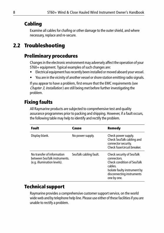
CablingExamine all cables for chafing or other damage to the outer shield, and where necessary, replace and re-secure.
2.2 Troubleshooting
Preliminary proceduresChanges in the electronic environment may adversely affect the operation of your ST60+ equipment. Typical examples of such changes are:• Electrical equipment has recently been installed or moved aboard your vessel.• You are in the vicinity of another vessel or shore station emitting radio signals.
If you appear to have a problem, first ensure that the EMC requirements (see Chapter 3, Installation ) are still being met before further investigating the problem.
Fixing faultsAll Raymarine products are subjected to comprehensive test and quality assurance programmes prior to packing and shipping. However, if a fault occurs, the following table may help to identify and rectify the problem.
Technical supportRaymarine provides a comprehensive customer support service, on the world wide web and by telephone help line. Please use either of these facilities if you are unable to rectify a problem.
Fault Cause Remedy
Display blank. No power supply. Check power supply.Check SeaTalk cabling and connector security. Check fuse/circuit breaker.
No transfer of information between SeaTalk instruments. (e.g. illumination levels).
SeaTalk cabling fault. Check security of SeaTalk connectors.Check condition of SeaTalk cables.Isolate faulty instrument by disconnecting instruments one by one.

Chapter 2: Maintenance & Troubleshooting 9
81264_1.book Page 9 Monday, December 5, 2005 9:16 AM
World wide webPlease visit the Customer Support area of our web site at:• www.raymarine.com
As well as providing a comprehensive Frequently Asked Questions section and servicing information, the web site gives e-mail access to the Raymarine Technical Support Department and a details of the locations of Raymarine agents, worldwide.
Telephone help lineIf you do not have access to the world wide web, please call our help line.
In the USA, call:• +1 800 539 5539, extension 2444 or• +1 603 881 5200 extension 2444
In the UK, Europe the Middle East or the Far East, call:• +44 (0) 23 9271 4713 (voice)• +44 (0) 23 9266 1228 (fax)
Help us to help youWhen requesting service, please quote the following product information:• Equipment type.• Model number.• Serial number.• Software issue number.
To find out the software version number of your ST60+ Wind or Close Hauled Wind instrument:
1. During normal operation, hold down the disp and true/app buttons for approximately 4 seconds, to display the software version.
2. Note the software version number, then hold down the disp and true/app buttons for approximately 2 seconds, to return to normal operation.
Software version D8248-1
CAL

10 ST60+ Wind & Close Hauled Wind Instrument Owner’s Handbook
81264_1.book Page 10 Monday, December 5, 2005 9:16 AM
11
81264_1.book Page 11 Monday, December 5, 2005 9:16 AM
Chapter 3: InstallationThis chapter describes how to install the ST60+ Wind and ST60+ Close Hauled Wind instruments, and associated wind transducer.
You can use any one of three Raymarine wind transducer types in conjunction with the ST60+ Wind instruments:• Cruiser wind vane (short arm). Typically mounted on a mast head.• Competition wind vane (long arm). Typically mounted on a mast head.• Rotavecta. Typically mounted on a rail or radar arch.
The transducer is connected to the rear of the instrument.
Note: The ST60+ Close Hauled Wind instrument does not connect directly to a wind trans-ducer.
For advice, or further information regarding the installation of this equipment, please contact the Raymarine Product Support Department or your own National Distributor.
3.1 Planning your installationBefore starting the installation, spend some time considering the best positions for both transducer and instrument, such that the Site requirements and the EMC installation guidelines are satisfied.
Site requirements
Transducers Each transducer type has a cable connected, and is supplied with a junction box and a set of spade terminals.
The transducer location must:• Allow reasonable access for installation and servicing.• Be as high as possible and away from any equipment which may shield the
transducer or otherwise disturb the air flow.• Provide a horizontal mounting surface. If a surface (e.g. mast top) is otherwise
suitable but not horizontal, make up a suitable wedged packing piece to pro-vide the necessary horizontal surface.
There must also be a viable route for the transducer cable to be routed to the instrument.
12 ST60+ Wind & Close Hauled Wind Instrument Owner’s Handbook
81264_1.book Page 12 Monday, December 5, 2005 9:16 AM
Instrument
2.7 in (68 mm)
1.5 in (38 mm)
D6905-1
9.76
in (2
48 m
m)
10.7 in (272 mm)
21.2 in (538.5 mm)
7.4 in (187 mm)
Appr
ox 1
6.8
in (4
26 m
m)*
2.76 in (70 mm)Wind VaneRotavecta
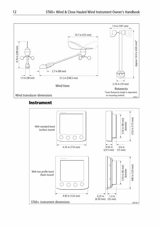
*Exact Rotavecta height is dependent on mounting method.Wind transducer dimensions
4.33 in (110 mm) 0.93 in(23.5 mm)
0.6 in(15 mm)
3.54
in (9
0 m
m)
diam
eter
4.53
in (1
15 m
m)
4.90 in (124 mm) 0.25 in(6.50 mm)
1.4 in(35 mm)
3.54
in (9
0 m
m)
diam
eter
490
in (1
24 m
m)
D8146-1ST60+ instrument dimensions
With standard bezel (surface mount)
With low profile bezel (flush mount)

Chapter 3: Installation 13
81264_1.book Page 13 Monday, December 5, 2005 9:16 AM
ST60+ instruments can be fitted either above or below deck, provided the rear of the instrument is sited where it is protected from contact with water.
Each instrument must also be positioned where:• It is easily read by the helmsman• It is protected against physical damage• It is at least 9 in (230 mm) from a compass• It is at least 20 in (500 mm) from radio receiving equipment• There is reasonable rear access for installation and servicing
EMC installation guidelinesAll Raymarine equipment and accessories are designed to the best industry standards for use in the recreational marine environment.
Their design and manufacture conforms to the appropriate Electromagnetic Compatibility (EMC) standards, but correct installation is required to ensure that performance is not compromised. Although every effort has been taken to ensure that they will perform under all conditions, it is important to understand what factors could affect the operation of the product.
The guidelines given here describe the conditions for optimum EMC performance, but it is recognized that it may not be possible to meet all of these conditions in all situations. To ensure the best possible conditions for EMC performance within the constraints imposed by any location, always ensure the maximum separation possible between different items of electrical equipment.
For optimum EMC performance, it is recommended that wherever possible:• Raymarine equipment and cables connected to it are:
• At least 3 ft (1 m) from any equipment transmitting or cables carrying radio signals e.g. VHF radios, cables and antennas. In the case of SSB radios, the distance should be increased to 7 ft (2 m).
• More than 7 ft (2 m) from the path of a radar beam. A radar beam can nor-mally be assumed to spread 20 degrees above and below the radiating element.
• The equipment is supplied from a separate battery from that used for engine start. Voltage drops below 10 V in the power supply to our products, and
CAUTION: Keep the rear of the instrument dryKeep the rear of instrument dry. Failure to observe this caution could result in damage if water enters the instrument through the breathing hole or comes into contact with the electrical connectors.

14 ST60+ Wind & Close Hauled Wind Instrument Owner’s Handbook
81264_1.book Page 14 Monday, December 5, 2005 9:16 AM
starter motor transients, can cause the equipment to reset. This will not dam-age the equipment, but may cause the loss of some information and may change the operating mode.
• Raymarine specified cables are used. Cutting and rejoining these cables can compromise EMC performance and must be avoided unless doing so is detailed in the installation manual.
• If a suppression ferrite is attached to a cable, this ferrite should not be removed. If the ferrite needs to be removed during installation it must be reas-sembled in the same position.
Suppression FerritesThe following illustration shows typical cable suppression ferrites used with Raymarine equipment. Always use the ferrites supplied by Raymarine.
Connections to Other EquipmentIf your Raymarine equipment is to be connected to other equipment using a cable not supplied by Raymarine, a suppression ferrite MUST always be attached to the cable near the Raymarine unit.
3.2 ProcedureAs it is not practical to describe procedures for all possible installation scenarios, the procedures given here describe the broad requirements for installing wind transducers and ST60+ Wind instruments. Adapt these procedures as appropriate, to suit your individual requirement.
UnpackingUnpack your ST60+ instrument and check that the items described in the Preface are present.
CAUTION: Maintain structural safetyWhere it is necessary to cut holes (e.g. for cable routing and instrument mounting), ensure that these will not cause a hazard by weakening critical parts of the vessel’s structure.
D3548-6

Chapter 3: Installation 15
81264_1.book Page 15 Monday, December 5, 2005 9:16 AM
Each ST60+ instrument is supplied with a standard bezel for surface mounting. Optional mounting kits are available for flush mounting and bracket mounting the instrument. If you have ordered the flush mounting option a low-profile bezel and four fixing screws are also provided.
Fitting the 1instrumentsThe ST60+ Wind and ST60+ Close Hauled Wind instruments can be installed using one of a number of different mounting options:• Surface mounting. Gives a profile of approximately 0.95 in (24 mm).• Flush mounting. Gives a profile of approximately 0.25 in (6 mm).• Bracket mounting.The ST60+ instruments can also be mounted behind a panel with just the instrument dial and buttons visible.
Surface mountingTo surface mount your ST60+ instrument (see the Surface mounting illustration):1. Ensure that:
• The selected location is clean, smooth and flat.• There is sufficient space behind the location to accommodate the rear of
the instrument and connectors.
Surface mounting4 1 2 1 3 5 52
D814
7-1

16 ST60+ Wind & Close Hauled Wind Instrument Owner’s Handbook
81264_1.book Page 16 Monday, December 5, 2005 9:16 AM
2. Apply the surface mount template (supplied at the rear of this handbook) to the selected location and mark the centers for the fixing studs (1) and the aperture (3) that will take the rear casing of the instrument.
3. Drill out the two 0.2 in (5 mm) fixing stud clearance holes (2). 4. Cut out the clearance hole (3) then remove the template.5. Peel off the protective sheet from the self-adhesive gasket (4) then stick the
gasket into position on the rear of the instrument.6. Screw the two fixing studs into the threaded sockets on the rear of the instru-
ment.7. Mount the assembled instrument, studs, bezel and gasket into the panel.
Secure from behind with the thumb nuts (5).
Flush mountingThe Flush Mounting Kit uses a low-profile bezel to reduce the fitted profile of the instrument, to approximately 0.25 in (6 mm) above the panel fascia.
Fitting the flush mount bezelIn order to flush-mount your ST60+ instrument, you must first replace the standard bezel with the flush mount bezel as follows:1. Hold the instrument in both hands with the display towards you.2. Using both thumbs, gently press an upper corner of the instrument from the
bezel, then remove the bezel from the instrument. Retain the rubber keypad which is released when the bezel is removed.
3. Referring to the Fitting the flush mount bezel illustration, insert the panel seal (8) in the corresponding recess on the back of the flush mount bezel (7).
D814
8-1

Chapter 3: Installation 17
81264_1.book Page 17 Monday, December 5, 2005 9:16 AM
4. Place the instrument (11) face upwards on a flat surface, then place the rub-ber keypad (10) in position around the display window (i.e. so that each but-ton outline is located over its associated button on the instrument).
5. Place the keypad seal (9) in position on the keypad (i.e. so that the holes in the seal accept the appropriate keypad buttons).
6. Place the assembled flush mount bezel and panel seal, in position on the instrument, so that the rubber keys are correctly located in the holes on the bezel, then clip the bezel and instrument together.
7. Using the four, self-tapping screws (12) provided, secure the instrument and bezel together. Fit the screws from the rear of the instrument and tighten them sufficiently to secure the instrument and bezel together. DO NOT OVER-TIGHTEN.
CAUTION: Use the correct screwsIt is essential that only screws of the correct size are used to secure the instrument to the bezel. Failure to observe this caution could result in damage to both the instrument and the bezel.
Fitting the flush mount bezel
87 9 10 11 12D8
149-
1

18 ST60+ Wind & Close Hauled Wind Instrument Owner’s Handbook
81264_1.book Page 18 Monday, December 5, 2005 9:16 AM
Flush mounting procedureFlush mount your instrument (see the Flush mounting illustration) as follows:1. Assemble the ST60+ instrument and flush mount bezel as described under
Fitting the flush mount bezel .2. Ensure that:
• The panel on which you intend to mount the instrument is between 0.12 in (3 mm) and 0.78 in (20 mm) thickness.
• The selected location is clean, smooth and flat.• There is sufficient space behind the location to accommodate the rear of
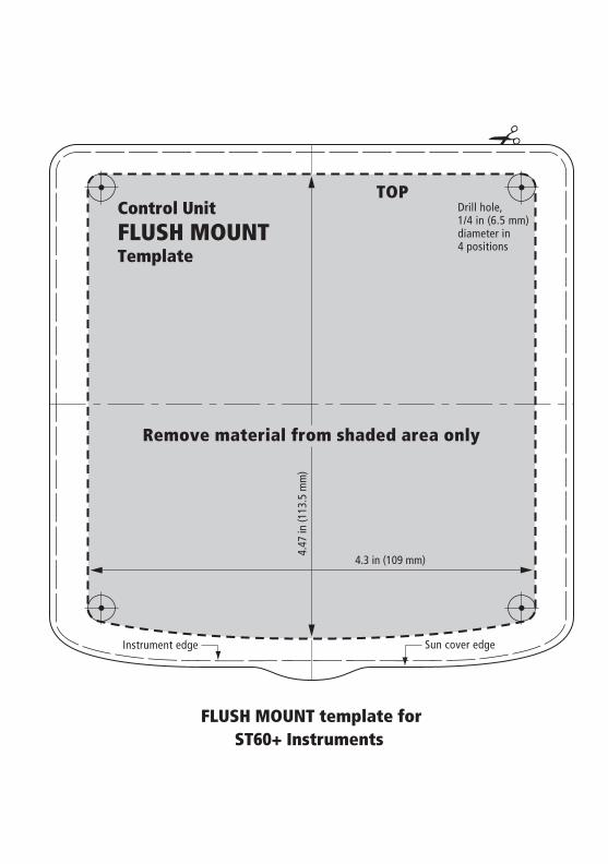
the instrument and connectors.3. Apply the flush mount template (supplied at the rear of this handbook) to the
selected location and mark out the aperture into which the assembled instru-ment and bezel will sit.
4. Cut out the aperture (3) for the assembled instrument and bezel and remove the template.
5. Peel off the protective sheet from the self-adhesive gasket (4) then stick the gasket into position on the rear of the bezel.
Flush mounting41 3 5 6 51
D815
0-1

Chapter 3: Installation 19
81264_1.book Page 19 Monday, December 5, 2005 9:16 AM
6. Screw the two fixing studs (1) into the threaded sockets on the rear of the instrument.
7. Mount the assembled instrument, studs, bezel and gasket into the panel. 8. Locate the flush mount bracket (6) onto the fixing studs and secure the assem-
bly to the panel with the thumb-nuts (5).
Bracket MountingA Control Unit Mounting Bracket (Part No. E25009) enables you to mount your ST60+ instrument in locations where other forms of mounting are impractical. Although this provides a useful alternative method for securing your instrument, it is only suitable for use in positions where the instrument will not be exposed to water.
To bracket mount your ST60+ instrument, do so in accordance with the Control Unit Mounting Bracket Instruction Sheet.
Fitting transducersIf you are fitting an ST60+ Wind instrument and wish to use it as a master instrument, you must also fit a wind transducer.
Note: An ST60+ Close Hauled Wind instrument can only be used as a repeater instru-ment, so a directly-connected transducer is not required.
Typical wind vane installationNote: Do NOT remove the connector cap from the wind vane base connector, until you are ready to fit the wind vane arm.
The wind vane base must be horizontal. If necessary, make up a suitable packing piece to provide a horizontal mounting surface.
D6954-1
RotavectaWind vane
Typical transducers

20 ST60+ Wind & Close Hauled Wind Instrument Owner’s Handbook
81264_1.book Page 20 Monday, December 5, 2005 9:16 AM
You can fit your wind vane so the cable leaves the wind vane base either from the rear (option A), or from underneath (option B).
A wind vane is typically mounted on a mast top, as follows:1. Mark the mounting surface for drilling. The recommended method for doing
this depends on which cable option you intend to use:• For cable option A, place the wind vane base in the intended position,
with the front end facing forwards, and mark the position of the two fixing screw holes.
• For cable option B, use the template at the rear of this handbook, to mark the position of the two fixing screw holes and the cable hole.
2. Drill the mounting surface for the cable option you intend to use:• For cable option A, drill a 4 mm hole at each of the marked locations for
the fixing screw holes.• For cable option B, drill a 4 mm hole at each of the marked locations for
the fixing screw holes and an 8 mm hole at the marked location for the cable.
Packing piece, if required
D6868-2
View from underneath showing arrangement of cable
Cutaway view, showing arrangement of cable
Option A Option B
D6870-3Wind vane cable options
Mounting surface

Chapter 3: Installation 21
81264_1.book Page 21 Monday, December 5, 2005 9:16 AM
3. Referring to the Wind vane cable options illustration, route the cable cor-rectly for the option you are using, then secure the wind vane base, using the two self-tapping fixing screws.
4. Insert the wind vane arm into the wind vane base connector and tighten the locking ring securely by hand.
RotavectaThe Rotavecta can be clamped to a 0.9 in (23 mm) or a 1 in (25 mm) rail by means of an integral clamp. To fit a Rotavecta:1. Dismantle the integral clamp, and ensure the pointed end of the grub screw
does not protrude through the top of the lower clamp section. [
D6836-2
Base
Connector cap
Locking ring
Fixingscrews
Arm
Clamp screws
Rail mount disc
Spacers
Grub screw
Rotavecta rail clamp D4308-2

22 ST60+ Wind & Close Hauled Wind Instrument Owner’s Handbook
81264_1.book Page 22 Monday, December 5, 2005 9:16 AM
2. If the rail is 1 in (25 mm) diameter, set aside the two spacers. If the rail is between 0.9 in (23 mm) and 1 in (25 mm) diameter, place the spacers in the lower part of the clamp.
3. Offer up the lower part of the clamp (and spacers if used) underneath the rail.4. Place the rail mount disc on the upper side of the rail and place the upper part
of the Rotavecta on top of this, so that all the screw holes are in alignment.5. Secure all sections together using the two fixing screws, but do not fully
tighten at this stage.6. Ensure the main shaft of the Rotavecta is vertical, then tighten the two fixing
screws.7. Screw in the grub screw, to pinch the rail.
Running transducer cable
GeneralEach transducer type is supplied with sufficient cable already connected, to run from the mounted position to the ST60+ Wind instrument. The manner in which you run the cable will depend on the locations of the transducer and instrument.
Observing the following guidelines, run the transducer cable to the instrument:• If the cable has to be fed through the deck, always use a proprietary deck
gland.• Where cables are fed through holes, always use grommets to prevent chafing.• Secure long cable runs so they do not present a hazard.• If the transducer is mounted on a masthead or other structure likely to be
removed for maintenance or storage purposes (e.g. a mast), always incorpo-rate a junction box into the cable run as close as possible to the cable entry point into the vessel, to facilitate disconnection when required.
• Although the transducer cable is fitted with spade connectors for direct con-nection to the rear of the instrument, it may be necessary to remove these to facilitate installation, e.g. if the cable has to be routed through narrow aper-tures. Extra spade connectors are provided, to replace any that are removed when running the cable. When fitting spade connectors, prepare the cable as at (a) in the following illustration, then fold back the wire strands and insert into the spade connector as at (b). Ensure the wire strands do not extend beyond the rear of the spade connector insulation, then crimp the connector to the wire.

Chapter 3: Installation 23
81264_1.book Page 23 Monday, December 5, 2005 9:16 AM
From masthead If the transducer is fitted on a masthead:1. Remove the spade connectors from the free end of the cable, then feed the
free end of the cable down inside the mast.• If the mast is a through-deck mast, feed the cable out through a suitable
below-decks aperture.• If the mast is deck stepped, feed the cable through the deck, using a pro-
prietary deck gland.2. Fit the junction box inside the vessel, close to the cable entry point.3. Run the cable to the junction box, then allowing sufficient cable to connect
inside the junction box, cut the cable and connect each wire at the free end of the cable from the transducer, to a separate connector inside the junction box.
3 mm
6 mm50 mm
(a)
(b)D4467-7
Mast head
Junction box
Typical transducer cable run D821
2-1
24 ST60+ Wind & Close Hauled Wind Instrument Owner’s Handbook
81264_1.book Page 24 Monday, December 5, 2005 9:16 AM
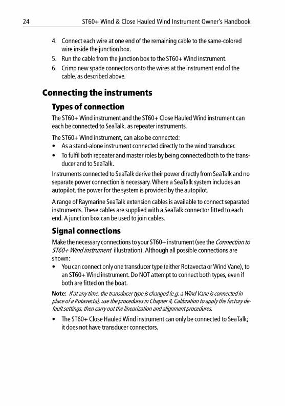
4. Connect each wire at one end of the remaining cable to the same-colored wire inside the junction box.
5. Run the cable from the junction box to the ST60+ Wind instrument.6. Crimp new spade connectors onto the wires at the instrument end of the
cable, as described above.
Connecting the instruments
Types of connectionThe ST60+ Wind instrument and the ST60+ Close Hauled Wind instrument can each be connected to SeaTalk, as repeater instruments.
The ST60+ Wind instrument, can also be connected:• As a stand-alone instrument connected directly to the wind transducer.• To fulfil both repeater and master roles by being connected both to the trans-
ducer and to SeaTalk.
Instruments connected to SeaTalk derive their power directly from SeaTalk and no separate power connection is necessary. Where a SeaTalk system includes an autopilot, the power for the system is provided by the autopilot.
A range of Raymarine SeaTalk extension cables is available to connect separated instruments. These cables are supplied with a SeaTalk connector fitted to each end. A junction box can be used to join cables.
Signal connectionsMake the necessary connections to your ST60+ instrument (see the Connection to ST60+ Wind instrument illustration). Although all possible connections are shown:• You can connect only one transducer type (either Rotavecta or Wind Vane), to
an ST60+ Wind instrument. Do NOT attempt to connect both types, even if both are fitted on the boat.
Note: If at any time, the transducer type is changed (e.g. a Wind Vane is connected in place of a Rotavecta), use the procedures in Chapter 4, Calibration to apply the factory de-fault settings, then carry out the linearization and alignment procedures.
• The ST60+ Close Hauled Wind instrument can only be connected to SeaTalk; it does not have transducer connectors.

Chapter 3: Installation 25
81264_1.book Page 25 Monday, December 5, 2005 9:16 AM
Power supply connections
SeaTalk systemsEnsure that the power supply for the SeaTalk bus is protected by a 5 A fuse or circuit breaker.
Systems with a large number of instruments on the SeaTalk bus may require connections to the power supply from each end of the system (‘ring-main’ style), to maintain sufficient voltage throughout the system.
This requirement depends on the total length of the cable run and the total number of instruments in the system, as follows:
CAUTION: Protect the power supplyEnsure that the 12 V power supply for the instrument is protected by a suitably rated fuse or protective circuit breaker.
Cable run No. of instruments Power connections
Up to 10 m 13 maximum26 maximum
12
Up to 20 m 7 maximum13 maximum
12
D818
8-1
Blue
Red
Green
YellowScreen
Cable from Rotavecta
Cable from Wind Vane
SeaTalk cable SeaTalk cable
Connections to ST60+ Wind instrument
Blue
Red

26 ST60+ Wind & Close Hauled Wind Instrument Owner’s Handbook
81264_1.book Page 26 Monday, December 5, 2005 9:16 AM
Stand alone instrumentsStand-alone instruments are not connected to SeaTalk and therefore need to be connected to an alternative 12 V power source. Power cables are available in 2 m and 9 m lengths.
To fit a power cable:1. Ensure the intended power source is switched off.2. Run the power cable from the instrument to a suitable 12 V dc power source.3. If the cable has not already been trimmed at the power supply end:
i. Cut the cable to length and trim back an appropriate amount of the outer sheath.
ii. Cut back and insulate the yellow wire.4. Connect the screen to the power supply 0 V terminal.5. Connect the red wire, via a 3 A fuse or protective circuit breaker, to the power
supply +12 V terminal.6. Insert the power cable connector into one of the SeaTalk connectors at the
rear of the instrument.
D4311-1
5 A fused,12 V dc supply
(typically providedby autopilot)
Red
Screen
Red
Screen
1 2 3 4
Instruments5 to 16
17181920
SeaTalk power connections
Power connections for stand-alone instrument
12 V dcsupply
3 A over-currentcircuit breaker
Red
Screen
D4310-4
Chapter 3: Installation 27
81264_1.book Page 27 Monday, December 5, 2005 9:16 AM
3.3 Switching onSwitch on the power to your ST60+ instrument. When the power is on, you can use the disp button to switch the instrument on and off as described in Chapter 1, Operation.
Use the procedure in Chapter 1, Operation to set the backlighting to the level you want.
EMC conformanceAlways check the installation before going to sea to make sure that it is not affected by radio transmissions, engine starting etc.
WARNING: Calibration requirementTo ensure this product performs at its best on your boat, you MUST calibrate it before use, in accordance with the instructions in Chapter 4, Calibration. Do NOT use the product until you have successfully calibrated it.

28 ST60+ Wind & Close Hauled Wind Instrument Owner’s Handbook
81264_1.book Page 28 Monday, December 5, 2005 9:16 AM
29
81264_1.book Page 29 Monday, December 5, 2005 9:16 AM
Chapter 4: Calibration
4.1 IntroductionThe ST60+ Wind instruments are set up with factory-programmed default settings, so in order to optimize the performance of the instruments on board a particular vessel, the procedures in this Chapter must be carried out immediately after the completion of installation, and before the equipment is used for navigational purposes.
Where practicable, the calibration procedures are presented diagrammatically to show the sequence of button presses and the resulting displays. Adjustment instructions are given as applicable.
4.2 User calibrationThe User calibration procedures:• Linearize and align the wind transducer.• Select the required wind speed units
Linearizing and aligning the wind transducerThis procedure ensures that the sensors in the wind vane transducer are correctly calibrated to record rotation of the wind vane, then compensates for any small errors which may exist in the alignment of the wind transducer.
To do this:1. Power-up the ST60+ Wind instrument.2. Slowly turn the vessel through two complete circles. This procedure automat-
ically linearizes the windvane. A successful linearization is indicated by the digital display flashing and the buzzer sounding three beeps.
3. Hold down the disp and true/app buttons for approximately 2 seconds to enter User calibration then use the disp button to select the wind angle offset screen (see the User calibration flow diagram, below).
4. Sail directly into the wind and adjust the analog pointer to zero, using the vmg and tack buttons. As you do this, the wind angle offset shows the amount of correction you have applied. If you are unable to achieve the required degree of accuracy due to sea conditions, and errors become appar-ent during subsequent tack operations, repeat this procedure to achieve alignment accuracy.

30 ST60+ Wind & Close Hauled Wind Instrument Owner’s Handbook
81264_1.book Page 30 Monday, December 5, 2005 9:16 AM
5. Display the wind speed units screen.
6. Use the vmg and tack buttons to select the units you want, either knots ( KTS ) or meters per second ( M/S ).
Note: Any speed unit changes will be applied to other SeaTalk instruments.
Leaving User calibrationHold down the disp and true/app buttons for 2 seconds to save your settings, exit User calibration and resume normal operation.
4.3 Intermediate calibrationThe intermediate calibration screens enable you to check:• The instrument software version number. This information is normally
required if you request parts or repairs.• The instrument status - either r0 (master) or r1 (repeater).
Hold down and for approximately 2 seconds
Entry screen
Wind speedunits
TRUE APP
TRUE APP
TRUE APP
Press either
or
to set the required windspeed units (KTS or M/S)
User calibration
disptrue
app
vmg tack
vmg tack
disp
disp
D818
9-1
Wind angle offset
Sail into wind & set pointer
to zero

Chapter 4: Calibration 31
81264_1.book Page 31 Monday, December 5, 2005 9:16 AM
To use the Intermediate calibration screens, hold down the disp and true/app buttons for approximately 4 seconds.
Leaving Intermediate calibrationHold down the disp and true/app buttons for 2 seconds to exit Intermediate calibration and resume normal operation.
4.4 Dealer calibrationThe Dealer calibration procedures enable you to set:• User calibration on/off. • Wind angle and speed response. • Velocity Made Good (VMG) response.• Wind speed calibration.• Boat show mode on/off.
Dealer calibration also gives access to the Factory defaults screen. This enables you to re-apply the factory settings if you want to reset the instrument to a known operating condition.
To commence Dealer calibration, hold down the disp and true/app buttons together for approximately 12 seconds, to select the Dealer calibration entry page (see Dealer calibration diagram, sheets 1 and 2). Then momentarily press the vmg and tack buttons to proceed with the calibration. As the calibration progresses, use the disp button to move from screen to screen.
Hold down and for approximately 4 seconds
Softwareversion
Instrumentstatus
Intermediate calibration
CAL
TRUE APP
TRUE APP
disptrue
app
disp
D819
0-1

32 ST60+ Wind & Close Hauled Wind Instrument Owner’s Handbook
81264_1.book Page 32 Monday, December 5, 2005 9:16 AM
TRUE APP
Hold down and for approximately 12 seconds
Dealer calibration - sheet 1
Entry screen
TRUE APP
TRUE APP
TRUE APP
Press momentarily
to toggle User calibrationeither on (UC1) or off (UC0)
Press
to set required response(A1) to (A15)
Press
to set required response(S1) to (S15)
Press
CALVMG
TRUE APP
go to sheet 2
User calibrationon/off
Wind angleresponse
Wind speedresponse
VMG response
to set required response(1) to (15)
Press
CAL
CAL
CAL
CAL
CAL
disptrue
app
vmg tack
orvmg tack
orvmg tack
orvmg tack
orvmg tack
disp
and
disp
disp
disp
D819
1-1
(not on Close Hauled Wind)
Chapter 4: Calibration 33
81264_1.book Page 33 Monday, December 5, 2005 9:16 AM
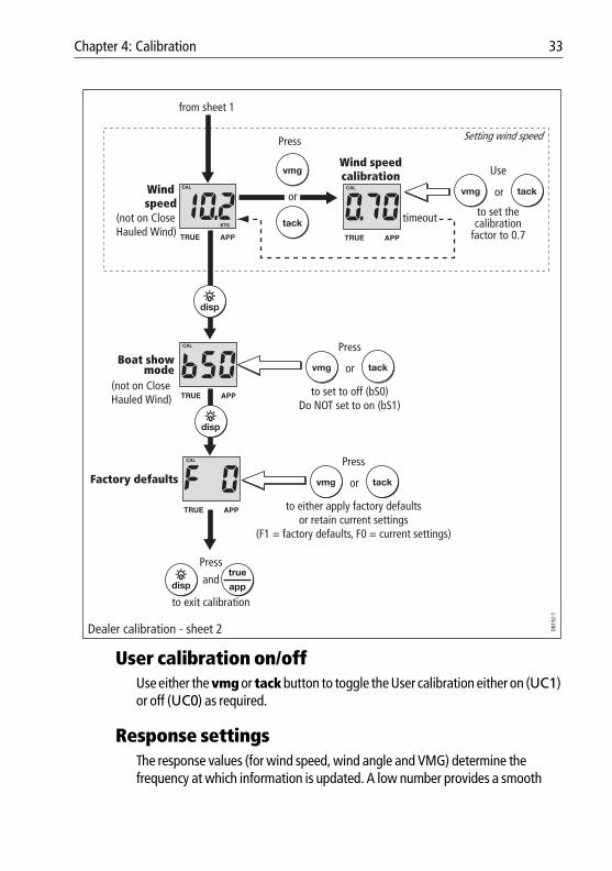
User calibration on/offUse either the vmg or tack button to toggle the User calibration either on (UC1) or off (UC0) as required.
Response settingsThe response values (for wind speed, wind angle and VMG) determine the frequency at which information is updated. A low number provides a smooth
and
to either apply factory defaultsor retain current settings
(F1 = factory defaults, F0 = current settings)
Press
from sheet 1
CAL
KTS
TRUE APP
CAL
TRUE APP
TRUE APP
Use
Press
Windspeed
Wind speedcalibration
Setting wind speed
to set to off (bS0)Do NOT set to on (bS1)
Press
Press
to exit calibration
Boat showmode
Factory defaults
Dealer calibration - sheet 2
CAL
disp
disp
orvmg tack
to set the calibration
factor to 0.7
timeout
vmg
or
tack
CAL
TRUE APP
disptrue
app
orvmg tack
orvmg tack
D819
2-1
(not on Close Hauled Wind)
(not on Close Hauled Wind)
34 ST60+ Wind & Close Hauled Wind Instrument Owner’s Handbook
81264_1.book Page 34 Monday, December 5, 2005 9:16 AM
response and a high number a much livelier response with rapid pointer movement.
Use the vmg (decrement) and tack (increment) buttons to set the required values. Response values are from 1 to 15 .
Wind speedThe Wind speed and Wind speed calibration screens are used to set the correct value for the wind speed. On entry (from the Wind speed response screen), the current value for apparent wind speed is displayed. Set the correct wind speed value, by applying a calibration factor as follows:
1. Use the vmg (decrement) and tack (increment) buttons to switch from the Wind Speed screen to the Wind Speed Calibration screen.
2. Use the vmg (decrement) or tack (increment) button to set the wind speed calibration factor to 0.7.
3. Timeout to the Wind Speed screen, and if further adjustment is necessary, repeat steps 1 and 2.
Boat show mode
Ensure that the Boatshow Mode Use is set to bS0 (disabled). If necessary, press either the vmg button or the tack button to achieve this.
Factory defaultsYou can use this screen to reset the operating parameters to the factory default values. Use the vmg and tack buttons to make the required selection.
Note that the selection you make at this screen will be applied when you exit the screen, so be sure you make the correct selection.
To retain the current values, ensure that the display shows NO.
If you want to apply the factory defaults, change the display to YES . If you do this, the values you have set up will be overwritten by the factory defaults when you leave this screen.
Leaving Dealer calibrationHold down the disp and true/app. buttons for 2 seconds to save your changes, exit Dealer calibration and resume normal operation.
CAUTION: Do NOT enable Boat Show ModeDo NOT enable Boat Show Mode. This must be used only for demonstration purposes.

35
81264_1.book Page 35 Monday, December 5, 2005 9:16 AM
Glossary
APP Apparent
AVE Average
AWA Apparent Wind Angle (relative to the vessel)
AWS Apparent Wind Speed
BTW Bearing To Waypoint
CMG Course Made Good
COG Course Over Ground
DMG Distance Made Good
DTW Distance To Waypoint
EMC Electro Magnetic Compatibility
ETA Estimated Time of Arrival
GPS Global Positioning System
HDG Heading
KM Kilometer(s)
KMH Kilometers per hour
KTS Knot(s)
LAT Latitude
LCD Liquid Crystal Display
LON Longitude
LTR Liter(s)

36 ST60+ Wind & Close Hauled Wind Instrument Owner’s Handbook
81264_1.book Page 36 Monday, December 5, 2005 9:16 AM
M Magnetic or meters
MAG Magnetic
MOB Man Overboard
MPH Miles per hour
NM Nautical mile(s)
Response The sensitivity of an instrument, to data changes.
RF Radio Frequency
SeaTalk Raymarine proprietary communication system which links products, to provide a single, integrated system sharing power and data.
SM Statute mile(s)
SOG Speed Over Ground
SPD Speed
T True
TTG Time To Go
TWA True Wind Angle relative to the vessel, taking into account the speed of the vessel.
TWD True Wind Direction.
TWS True Wind Speed.
VMG Velocity Made Good.
WP Waypoint
XTE Cross Track Error

37
81264_1.book Page 37 Monday, December 5, 2005 9:16 AM
Index
AAlarms, 4
canceling, 4setting conditions, 5
Aligning wind transducer, 29
BBacklighting adjustment, 6Boat show mode, 34
CCalibration alert, 1Calibration requirement, 1Cleaning, 7Condensation, 7DDealer calibration, 31Display setup, 6Displayed information, 2
digital display, 2pointer, 2tack heading, 4true/apparent, 3VMG, 4
Disposing of the product, iiEEMC information, i, 7, 13, 27
FFactory defaults, 34
HHelp lines, 9IInstalling
instrument, 15bracket mounting, 19flush mounting, 16power supply connections, 25requirements, 12signal connections, 24surface mounting, 15
planning, 11transducer, 19
requirements, 11Rotavecta, 21running cable, 22wind vane, 19
Instrument mounting options, ix, 15Intermediate calibration, 30
LLinearizing wind transducer, 29
MMounting options (instrument), ix, 15
PParts supplied, ix–xPower supply
SeaTalk systems, 25stand alone instrument, 26
Product disposal, iiRRemote control, viii, 6Rotavecta installation, 21
SSafety
calibration requirement, 1electrical, igeneral, inavigation, i
SeaTalk overview, viiiServicing & safety, 7Setting up
aligning wind transducer, 29applying factory defaults, 34backlighting, 6correct wind speed, 34instrument response, 33linearizing wind transducer, 29User calibration access, 33wind speed units, 29

38 ST60+ Wind & Close Hauled Wind Instrument Owner’s Handbook
81264_1.book Page 38 Monday, December 5, 2005 9:16 AM
Site requirementsinstrument, 12transducer, 11
Software version, 9, 30Switching on/off, 1, 27
TTack heading, 4Technical support, 8Troubleshooting, 8True/apparent selection, 4
UUser calibration, 29
VVelocity Made Good, 4WWind speed setup, 34Wind transducer
aligning, 29linearizing, 29
Wind vane installation, 19
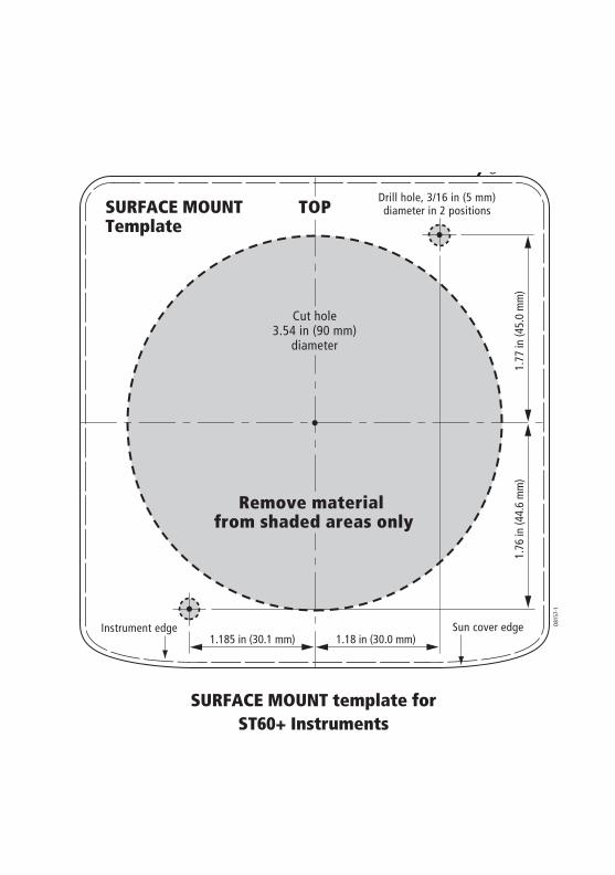
SURFACE MOUNT template for ST60+ Instruments
1.185 in (30.1 mm) 1.18 in (30.0 mm)
SURFACE MOUNTTemplate
Sun cover edge D815
7-1
Cut hole3.54 in (90 mm)
diameter
Drill hole, 3/16 in (5 mm)diameter in 2 positions
1.77
in (4
5.0
mm
)1.
76 in
(44.
6 m
m)
Remove material from shaded areas only
TOP
Instrument edge
81264_1.book Page 39 Monday, December 5, 2005 9:16 AM

81264_1.book Page 40 Monday, December 5, 2005 9:16 AM
81264_1.book Page 41 Monday, December 5, 2005 9:16 AM
4.3 in (109 mm)
4.47
in (1
13.5
mm
)
Sun cover edgeInstrument edge
Remove material from shaded area only
Drill hole,1/4 in (6.5 mm) diameter in4 positions
TOPControl UnitFLUSH MOUNTTemplate
FLUSH MOUNT template forST60+ Instruments

81264_1.book Page 42 Monday, December 5, 2005 9:16 AM

81264_1.book Page 43 Monday, December 5, 2005 9:16 AM
Front
50 mm
27.5 mm
34.5 mm
7 mm
10 mm
CenterLine
Drill hole, 4 mm diameter
Drill hole, 4 mm diameter
If cable is to leave base from underneath, drill hole, 8 mm diameter (not required if cable to exit from rear)
Wind vane drilling templateD6955-1
Edge of wind vane base

81264_1.book Page 44 Monday, December 5, 2005 9:16 AM