Embed Size (px)
Citation preview
Owner’s Installation and Operation Manual Model 1440E
United States Stove Company 227 Industrial Park Rd.
South Pittsburg, TN 37380 852836-3901F
Installation is to be preformed by a qualified installer.
SAVE THESE INSTRUCTIONS
This unit is certified UL-391(R2014)
U.S. ENVIRONMENTAL PROTECTION AGENCY Certified to comply with the 2016 particulate emission standards. Not approved for sale after
May 15, 2020
Report No. 0215WH055S
Wood Only Central Furnace
-2-
CAUTION:• Power source not controlled by furnace main disconnect.• Respect all local and national codes when installing this unit.• This unit is not to be connected to a chimney flue serving another appliance.• This unit is designed to burn solid hardwood only.
49”
24-1/16”
34”
2”
40”
34”
-3-
SpecificationsCONGRATULATIONS!
You’ve purchased a heater from North America’s oldest manufacturer of wood burning products.By heating with wood you’re helping to CONSERVE ENERGY!
Wood is our only Renewable Energy Resource. Please do your part to preserve our wood supply. Plant at least one tree each year. Future generations will thank you.
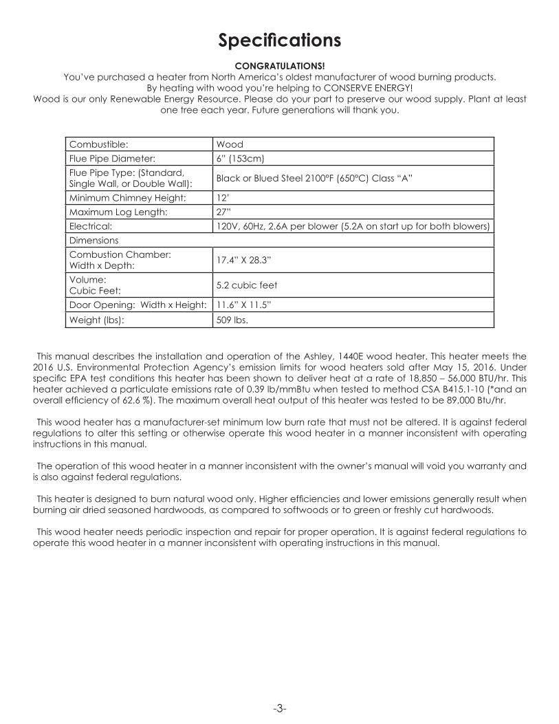
This manual describes the installation and operation of the Ashley, 1440E wood heater. This heater meets the 2016 U.S. Environmental Protection Agency’s emission limits for wood heaters sold after May 15, 2016. Under specific EPA test conditions this heater has been shown to deliver heat at a rate of 18,850 – 56,000 BTU/hr. This heater achieved a particulate emissions rate of 0.39 lb/mmBtu when tested to method CSA B415.1-10 (*and an overall efficiency of 62.6 %). The maximum overall heat output of this heater was tested to be 89,000 Btu/hr.
This wood heater has a manufacturer-set minimum low burn rate that must not be altered. It is against federal regulations to alter this setting or otherwise operate this wood heater in a manner inconsistent with operating instructions in this manual.
The operation of this wood heater in a manner inconsistent with the owner’s manual will void you warranty and is also against federal regulations.
This heater is designed to burn natural wood only. Higher efficiencies and lower emissions generally result when burning air dried seasoned hardwoods, as compared to softwoods or to green or freshly cut hardwoods.
This wood heater needs periodic inspection and repair for proper operation. It is against federal regulations to operate this wood heater in a manner inconsistent with operating instructions in this manual.
Combustible: WoodFlue Pipe Diameter: 6” (153cm)Flue Pipe Type: (Standard, Single Wall, or Double Wall): Black or Blued Steel 2100°F (650°C) Class “A”
Minimum Chimney Height: 12’Maximum Log Length: 27”Electrical: 120V, 60Hz, 2.6A per blower (5.2A on start up for both blowers)DimensionsCombustion Chamber: Width x Depth: 17.4” X 28.3”
Volume: Cubic Feet: 5.2 cubic feet
Door Opening: Width x Height: 11.6” X 11.5”Weight (lbs): 509 lbs.
-4-
Safety• WARNING: Do not operate with fuel loading or ash removal doors open.• Do not connect this unit to a chimney flue serving another appliance.• WARNING DANGER: Risk of fire or explosion. Do not burn garbage, gasoline, naphtha, motor oil, or other
inappropriate materials. Do not use chemicals or fluids to start the fire.• WARNING: Risk of fire. Do not operate with flue draft exceeding .060” water column/14.93 Pascals. Do not
operate with fuel loading and ash removal doors open. Do not store fuel or other combustible materials within marked installation clearances. Inspect and clean flues and chimney regularly.
• CAUTION: Hot surfaces. Keep children away. Do not touch during operation.• The heat exchanger, flue pipe, and chimney must be cleaned regularly to remove accumulated creosote
and ash. Ensure that the heat exchanger, flue pipe, and chimney are cleaned at the end of the heating season to minimize corrosion during the summer months. The appliance, flue pipe, and chimney must be kept in good condition. These instructions also apply to a draft inducer if used. To prevent flame or smoke spillage, the slide baffle must be pulled out and the fuel loading door left cracked for 10 seconds prior to opening door fully. Load fuel carefully or damage may result.
• Hot while in operation. Keep children, clothing and furniture away. Contact may cause skin burns.• Do not use chemicals or fluids to ignite the fire.• Do not leave the furnace unattended when the door is slightly opened.• Do not burn garbage, flammable fluid such as gasoline, naphtha or motor oil.• Always close the door after the ignition.• Consult your municipal building department or fire officials about permits, restrictions and installations
requirements in your area.• INSPECT FLUE PIPES, FLUE PIPE JOINTS, AND FLUE PIPE SEALS REGULARLY TO ENSURE THAT SMOKE AND FLUE
GASES ARE NOT DRAWN INTO, AND CIRCULATED BY, THE AIR-CIRCULATION SYSTEM.• CAUTION: CLEAN OUT OF THE HEAT EXCHANGER, FLUE PIPE CHIMNEY, AND DRAFT INDUCER, IF USED, IS
ESPECIALLY IMPORTANT AT THE END OF THE HEATING SEASON TO MINIMIZE CORROSION DURING THE SUMMER MONTHS, CAUSED BY ACCUMULATED ASH.
-5-
Unpacking And PreassembleUNPACKING1. Remove all packaging from the furnace.2. Remove the supplied parts from the furnace.
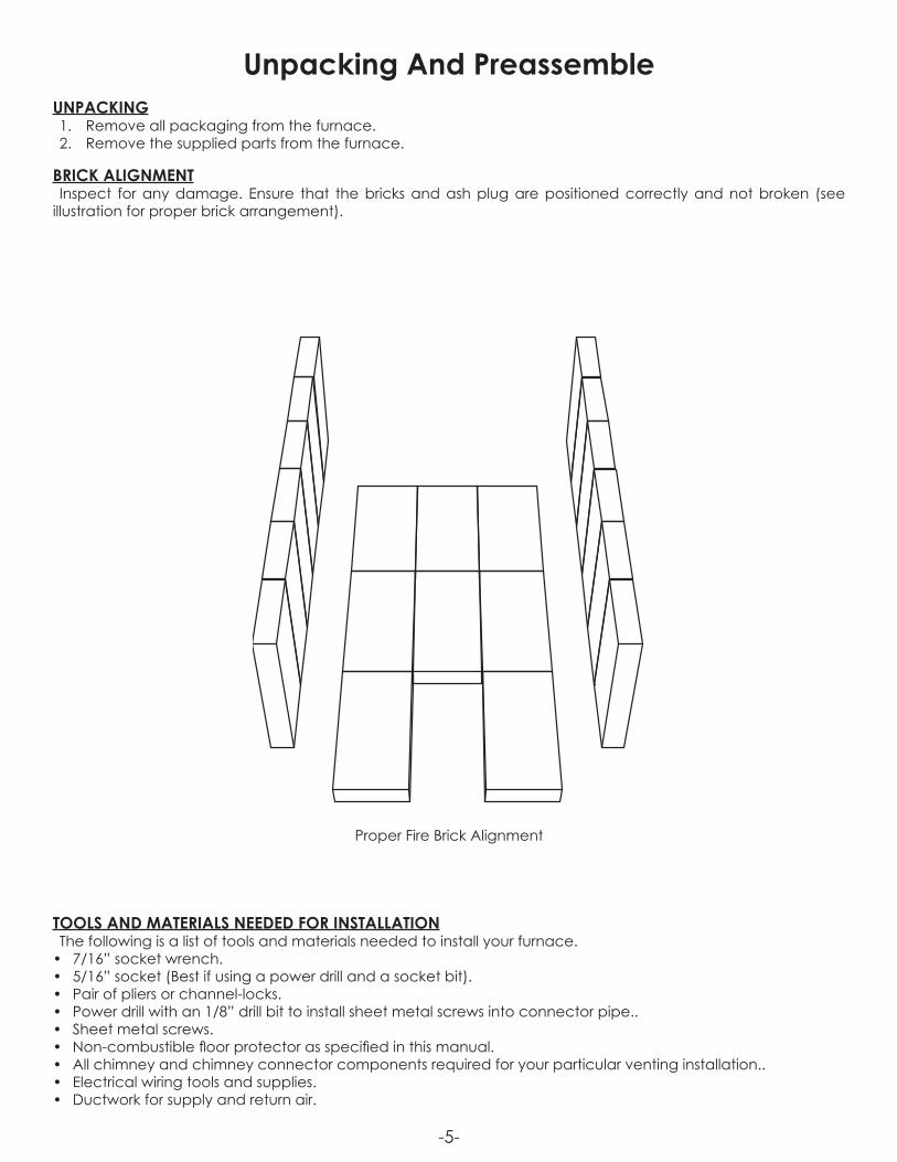
BRICK ALIGNMENTInspect for any damage. Ensure that the bricks and ash plug are positioned correctly and not broken (see
illustration for proper brick arrangement).
TOOLS AND MATERIALS NEEDED FOR INSTALLATIONThe following is a list of tools and materials needed to install your furnace.
• 7/16” socket wrench.• 5/16” socket (Best if using a power drill and a socket bit).• Pair of pliers or channel-locks.• Power drill with an 1/8” drill bit to install sheet metal screws into connector pipe..• Sheet metal screws.• Non-combustible floor protector as specified in this manual.• All chimney and chimney connector components required for your particular venting installation..• Electrical wiring tools and supplies.• Ductwork for supply and return air.
Proper Fire Brick Alignment
-6-
Furnace Installation
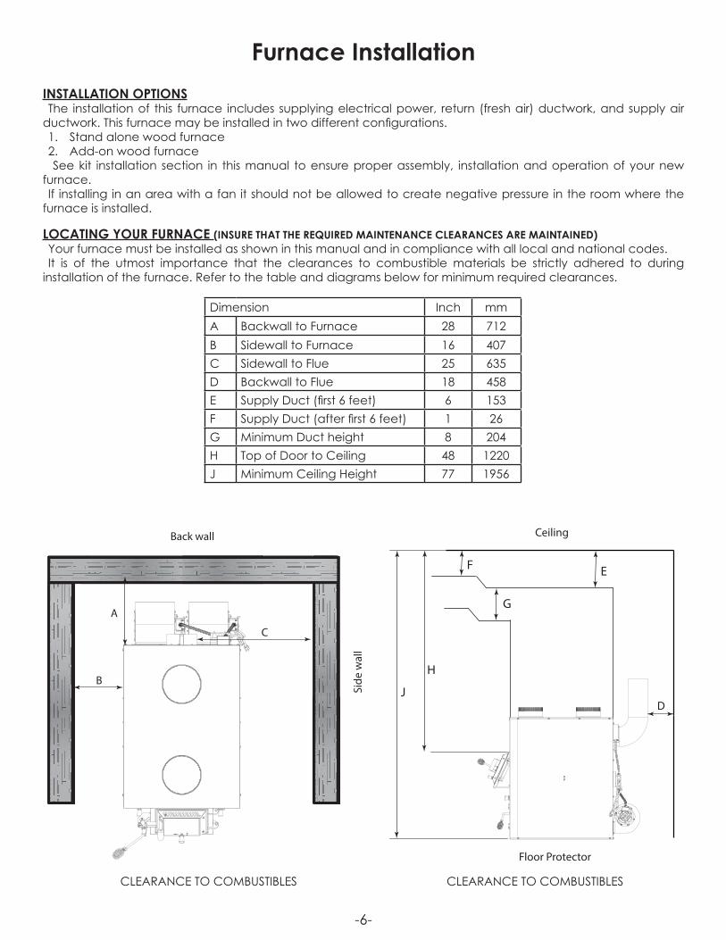
Dimension Inch mmA Backwall to Furnace 28 712B Sidewall to Furnace 16 407C Sidewall to Flue 25 635D Backwall to Flue 18 458E Supply Duct (first 6 feet) 6 153F Supply Duct (after first 6 feet) 1 26G Minimum Duct height 8 204H Top of Door to Ceiling 48 1220J Minimum Ceiling Height 77 1956
INSTALLATION OPTIONSThe installation of this furnace includes supplying electrical power, return (fresh air) ductwork, and supply air
ductwork. This furnace may be installed in two different configurations.1. Stand alone wood furnace2. Add-on wood furnace See kit installation section in this manual to ensure proper assembly, installation and operation of your new
furnace.If installing in an area with a fan it should not be allowed to create negative pressure in the room where the
furnace is installed.
LOCATING YOUR FURNACE (INSURE THAT THE REQUIRED MAINTENANCE CLEARANCES ARE MAINTAINED)Your furnace must be installed as shown in this manual and in compliance with all local and national codes.It is of the utmost importance that the clearances to combustible materials be strictly adhered to during
installation of the furnace. Refer to the table and diagrams below for minimum required clearances.
Back wall
Side
wal
l
Side
wal
l
Ceiling
Floor Protector
C
B
A
ML
N
K
EF
G
H
JD
Q
O
R
P
S S
Back wall
Side
wal
l
Side
wal
l
Ceiling
Floor Protector
C
B
A
ML
N
K
EF
G
H
JD
Q
O
R
P
S S
CLEARANCE TO COMBUSTIBLESCLEARANCE TO COMBUSTIBLES
-7-
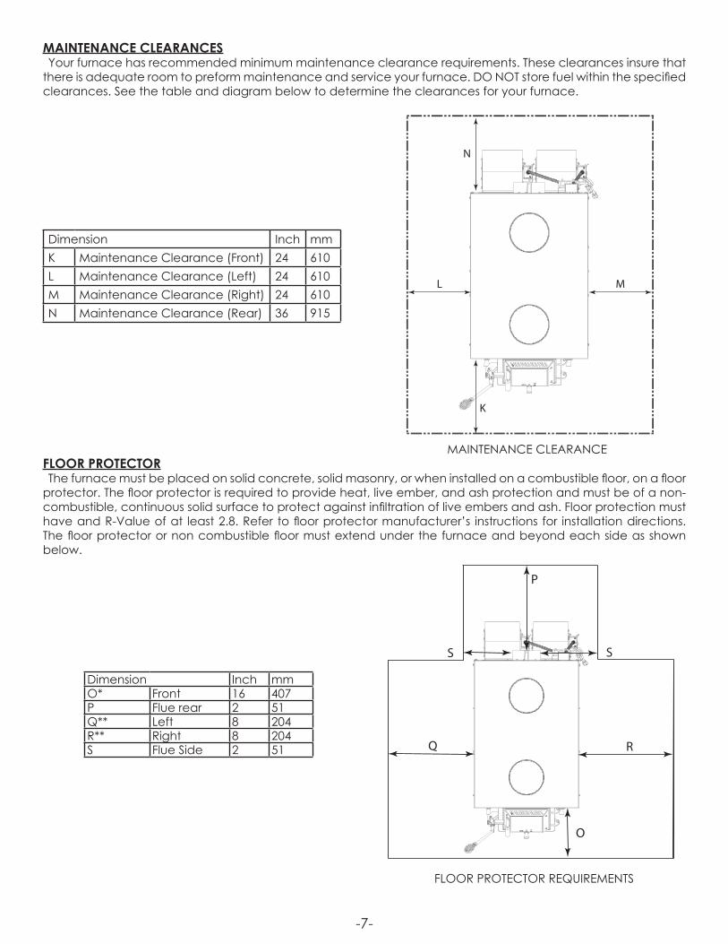
MAINTENANCE CLEARANCESYour furnace has recommended minimum maintenance clearance requirements. These clearances insure that
there is adequate room to preform maintenance and service your furnace. DO NOT store fuel within the specified clearances. See the table and diagram below to determine the clearances for your furnace.
Dimension Inch mmK Maintenance Clearance (Front) 24 610L Maintenance Clearance (Left) 24 610M Maintenance Clearance (Right) 24 610N Maintenance Clearance (Rear) 36 915
Back wall
Side
wal
l
Side
wal
l
Ceiling
Floor Protector
C
B
A
ML
N
K
EF
G
H
JD
Q
O
R
P
S S
Back wall
Side
wal
l
Side
wal
l
Ceiling
Floor Protector
C
B
A
ML
N
K
EF
G
H
JD
Q
O
R
P
S S
MAINTENANCE CLEARANCE
FLOOR PROTECTOR REQUIREMENTS
FLOOR PROTECTORThe furnace must be placed on solid concrete, solid masonry, or when installed on a combustible floor, on a floor
protector. The floor protector is required to provide heat, live ember, and ash protection and must be of a non-combustible, continuous solid surface to protect against infiltration of live embers and ash. Floor protection must have and R-Value of at least 2.8. Refer to floor protector manufacturer’s instructions for installation directions. The floor protector or non combustible floor must extend under the furnace and beyond each side as shown below.
Dimension Inch mmO* Front 16 407P Flue rear 2 51Q** Left 8 204R** Right 8 204S Flue Side 2 51

-8-
Duct Work InstallationWe strongly recommend that the hot air ductwork be installed by a home heating specialist. If doing the
installation yourself, before you decide which installation will best suit your needs, consult a qualified heating technician and follow his recommendations as to the safest and most efficient method of installation.This furnace can be installed in three ways, as a stand alone unit, parallel, and in series with an existing furnace.
SUPPLY AIR (HOT AIR) PLENUMThe warm-air supply duct shall be constructed of metal in accordance with NFPA 90B, 2-1.1. The plenums installed
to the furnace shall be constructed of metal in accordance with NFPA 90B, 2-1.3.When installing this furnace the hot air plenum is to have a minimum height of 24” (610mm) if the top of the first
vertical section is not flush with the top of the first horizontal section of ductwork. If the top of the plenum is flush with the top of the first horizontal section of ductwork then the minium height is 15” (381mm).
RETURN AIR (FRESH AIR)The return (fresh) air intake on the furnace is on the rear of the unit. The ductwork must be mechanically attached
to the unit or UFB908 blower box with sheet metal screws to ensure a proper operation.
STAND ALONE INSTALLATIONIf installing this furnace as a stand alone unit, ensure all local codes and all instructions in this manual are followed,
including clearance to combustibles, floor protector specifications and safety warnings.
24-1/16”6”
Supply Air (Hot Air) Duct Work Outlet Size
Supply Air Plenum Minimum Height Of 24”
Supply Air Plenum With Minimum Height Of 15”
-9-
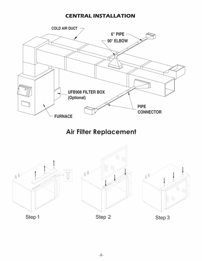
CENTRAL INSTALLATION
Air Filter Replacement
-10-
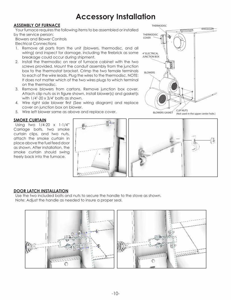
ASSEMBLY OF FURNACEYour furnace requires the following items to be assembled or installed
by the service person:Blowers and Blower ControlsElectrical Connections1. Remove all parts from the unit (blowers, thermodisc, and all
wiring) and inspect for damage, including the firebrick as some breakage could occur during shipment.
2. Install the thermodisc on rear of furnace cabinet with the two screws provided. Mount the conduit assembly from the junction box to the thermostat bracket. Crimp the two female terminals to each of the wire leads. Plug the wires to the thermodisc. NOTE: It does not matter which of the two wires plugs to which terminal on the thermodisc.
3. Remove blowers from cartons. Remove junction box cover. Attach clip nuts as in figure shown. Install blower(s) and gasket(s with 1/4"-20 x 3/4" bolts as shown.
4. Wire right side blower first (See wiring diagram) and replace cover on junction box on blower.
5. Wire left blower same as above and replace cover.
SMOKE CURTAINUsing two 1/4-20 x 1-1/4”
Carriage bolts, two smoke curtain clips, and two nuts, attach the smoke curtain in place above the fuel feed door as shown. After installation, the smoke curtain should swing freely back into the furnace.
Accessory InstallationTHERMODISC
THERMODISCCOVER
4” ELECTRICAL JUNCTION BOX
BLOWERS
BLOWERS GASKETCLIP NUTS(Not used in the upper center hole.)
DOOR LATCH INSTALLATIONUse the two included bolts and nuts to secure the handle to the stove as shown.Note: Adjust the handle as needed to insure a proper seal.
-11-
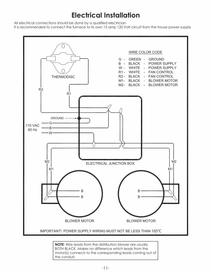
Electrical InstallationAll electrical connections should be done by a qualified electricianIt is recommended to connect the furnace to its own 15 amp 120 Volt circuit from the house power supply
105°C
NOTE: Wire leads from the distribution blower are usually BOTH BLACK. Makes no difference which leads from the motor(s) connects to the corresponding leads coming out of the conduit.
-12-
Chimney InstallationCHIMNEYYour wood furnace may be hooked up with a factory built or masonry chimney, matching the diameter of the
exhaust. If you are using a factory built chimney, it must comply with UL 103 or CSA-B365 standard; therefore it must be a Type HT (2100°F). It is extremely important that it be installed according to the manufacturer’s specifications.If you are using a masonry chimney, it is important that it be built in compliance with the specifications of the
National Building Code. It must be lined with fire clay bricks, metal or clay tiles sealed together with fire cement. (Round flues are the most efficient).The interior diameter of the chimney flue must be identical to the furnace smoke exhaust. A flue which is too
small may cause draft problems, while a large flue favors rapid cooling of the gas, and hence the build-up of creosote and the risk of chimney fires. Note that it is the chimney and not the furnace which creates the draft effect; your furnace’s performance is directly dependent on an adequate draft from your chimney.Do not connect this unit to a chimney flue serving another appliance.The following recommendations may be useful for the installation of your chimney:
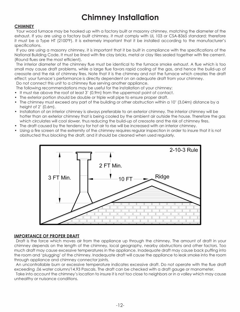
• It must rise above the roof at least 3’ (0.9m) from the uppermost point of contact.• The exterior portion should be double or triple wall pipe to ensure proper draft.• The chimney must exceed any part of the building or other obstruction within a 10’ (3.04m) distance by a
height of 2’ (0.6m).• Installation of an interior chimney is always preferable to an exterior chimney. The interior chimney will be
hotter than an exterior chimney that is being cooled by the ambient air outside the house. Therefore the gas which circulates will cool slower, thus reducing the build-up of creosote and the risk of chimney fires.
• The draft caused by the tendency for hot air to rise will be increased with an interior chimney.• Using a fire screen at the extremity of the chimney requires regular inspection in order to insure that it is not
obstructed thus blocking the draft, and it should be cleaned when used regularly.
IMPORTANCE OF PROPER DRAFTDraft is the force which moves air from the appliance up through the chimney. The amount of draft in your
chimney depends on the length of the chimney, local geography, nearby obstructions and other factors. Too much draft may cause excessive temperatures in the appliance. Inadequate draft may cause back puffing into the room and ‘plugging’ of the chimney. Inadequate draft will cause the appliance to leak smoke into the room through appliance and chimney connector joints.An uncontrollable burn or excessive temperature indicates excessive draft. Do not operate with the flue draft
exceeding .06 water column/14.93 Pascals. The draft can be checked with a draft gauge or manometer.Take into account the chimney’s location to insure it is not too close to neighbors or in a valley which may cause
unhealthy or nuisance conditions.
-13-
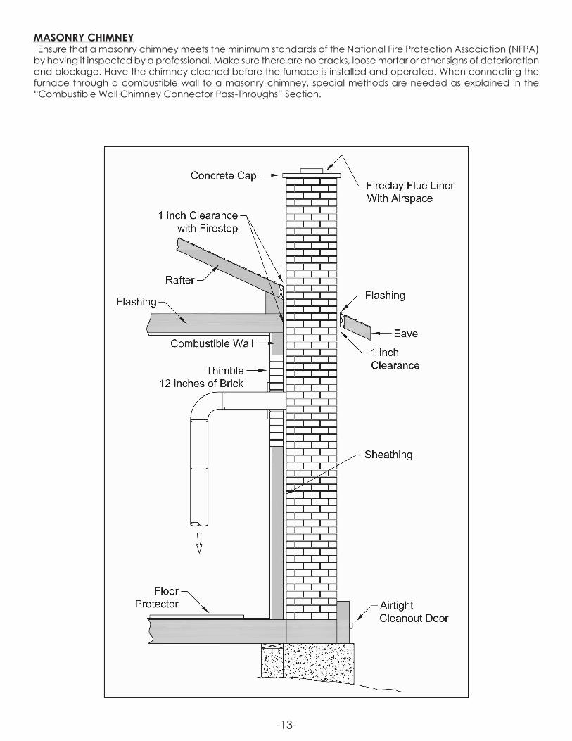
MASONRY CHIMNEYEnsure that a masonry chimney meets the minimum standards of the National Fire Protection Association (NFPA)
by having it inspected by a professional. Make sure there are no cracks, loose mortar or other signs of deterioration and blockage. Have the chimney cleaned before the furnace is installed and operated. When connecting the furnace through a combustible wall to a masonry chimney, special methods are needed as explained in the “Combustible Wall Chimney Connector Pass-Throughs” Section.
-14-
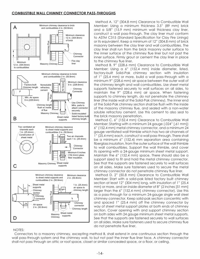
COMBUSTIBLE WALL CHIMNEY CONNECTOR PASS-THROUGHS
Method A. 12” (304.8 mm) Clearance to Combustible Wall Member: Using a minimum thickness 3.5” (89 mm) brick and a 5/8” (15.9 mm) minimum wall thickness clay liner, construct a wall pass-through. The clay liner must conform to ASTM C315 (Standard Specification for Clay Fire Linings) or its equivalent. Keep a minimum of 12” (304.8 mm) of brick masonry between the clay liner and wall combustibles. The clay liner shall run from the brick masonry outer surface to the inner surface of the chimney flue liner but not past the inner surface. Firmly grout or cement the clay liner in place to the chimney flue liner.Method B. 9” (228.6 mm) Clearance to Combustible Wall
Member: Using a 6” (152.4 mm) inside diameter, listed, factory-built Solid-Pak chimney section with insulation of 1” (25.4 mm) or more, build a wall pass-through with a minimum 9” (228.6 mm) air space between the outer wall of the chimney length and wall combustibles. Use sheet metal supports fastened securely to wall surfaces on all sides, to maintain the 9” (228.6 mm) air space. When fastening supports to chimney length, do not penetrate the chimney liner (the inside wall of the Solid-Pak chimney). The inner end of the Solid-Pak chimney section shall be flush with the inside of the masonry chimney flue, and sealed with a non-water soluble refractory cement. Use this cement to also seal to the brick masonry penetration.Method C. 6” (152.4 mm) Clearance to Combustible Wall
Member: Starting with a minimum 24 gauge (.024” [.61 mm]) 6” (152.4 mm) metal chimney connector, and a minimum 24 gauge ventilated wall thimble which has two air channels of 1” (25.4 mm) each, construct a wall pass-through. There shall be a minimum 6” (152.4) mm separation area containing fiberglass insulation, from the outer surface of the wall thimble to wall combustibles. Support the wall thimble, and cover its opening with a 24-gauge minimum sheet metal support. Maintain the 6” (152.4 mm) space. There should also be a support sized to fit and hold the metal chimney connector. See that the supports are fastened securely to wall surfaces on all sides. Make sure fasteners used to secure the metal chimney connector do not penetrate chimney flue liner.Method D. 2” (50.8 mm) Clearance to Combustible Wall
Member: Start with a solid-pak listed factory built chimney section at least 12” (304 mm) long, with insulation of 1” (25.4 mm) or more, and an inside diameter of 8” (2 inches [51 mm] larger than the 6” [152.4 mm] chimney connector). Use this as a pass-through for a minimum 24-gauge single wall steel chimney connector. Keep solid-pak section concentric with and spaced 1” (25.4 mm) off the chimney connector by way of sheet metal support plates at both ends of chimney section. Cover opening with and support chimney section on both sides with 24 gauge minimum sheet metal supports. See that the supports are fastened securely to wall surfaces on all sides. Make sure fasteners used to secure chimney flue do not penetrate flue liner.
NOTES: Connectors to a masonry chimney, excepting method B, shall extend in one continuous section through the
wall pass-through system and the chimney wall, to but not past the inner flue liner face. A chimney connector shall not pass through an attic or roof space, closet or similar concealed space, or a floor, or ceiling.
-15-
CHIMNEY CONNECTORYour chimney connector and chimney must have the same diameter as the furnace outlet. If this is not the case,
we recommend you contact your dealer in order to insure there will be no problem with the draft.The furnace pipe must be made of aluminized or cold roll steel with a minimum thickness of 0.021” or 0.53 mm. It
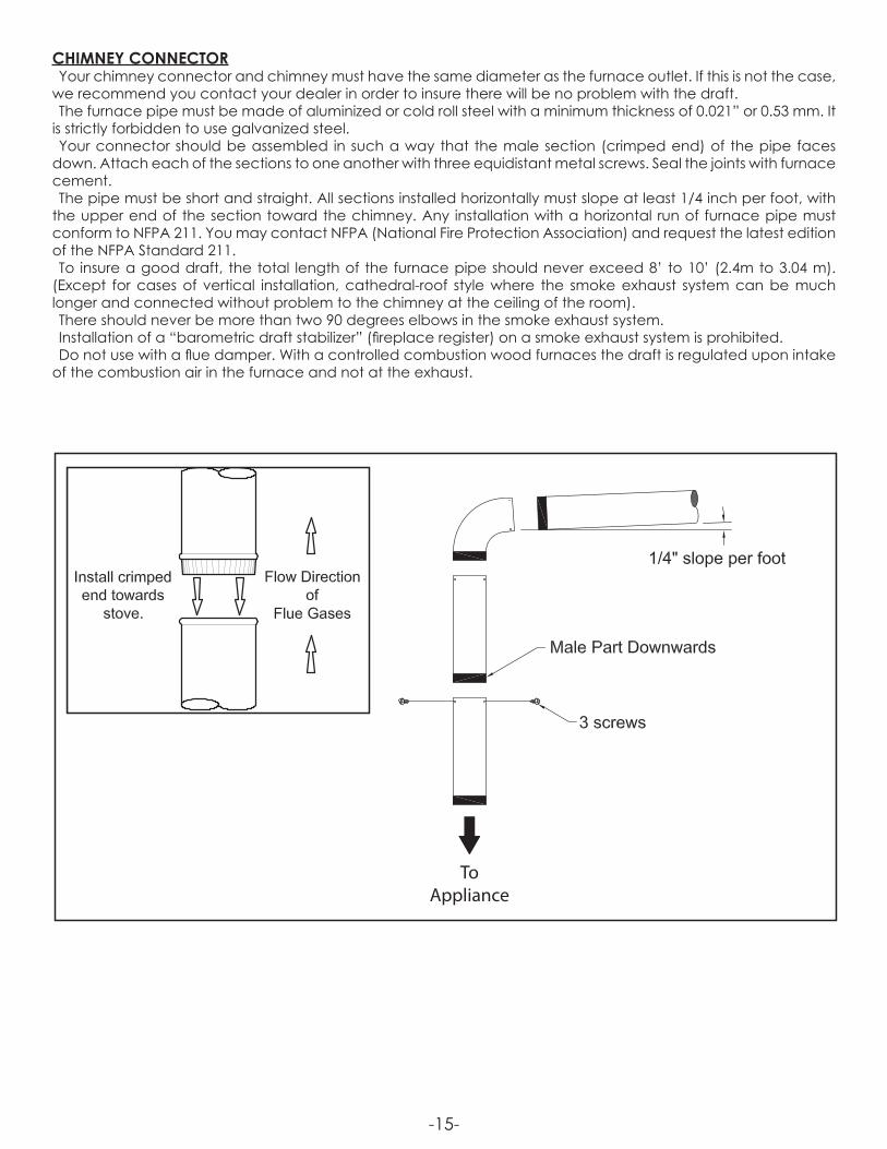
is strictly forbidden to use galvanized steel.Your connector should be assembled in such a way that the male section (crimped end) of the pipe faces
down. Attach each of the sections to one another with three equidistant metal screws. Seal the joints with furnace cement.The pipe must be short and straight. All sections installed horizontally must slope at least 1/4 inch per foot, with
the upper end of the section toward the chimney. Any installation with a horizontal run of furnace pipe must conform to NFPA 211. You may contact NFPA (National Fire Protection Association) and request the latest edition of the NFPA Standard 211.To insure a good draft, the total length of the furnace pipe should never exceed 8’ to 10’ (2.4m to 3.04 m).
(Except for cases of vertical installation, cathedral-roof style where the smoke exhaust system can be much longer and connected without problem to the chimney at the ceiling of the room).There should never be more than two 90 degrees elbows in the smoke exhaust system.Installation of a “barometric draft stabilizer” (fireplace register) on a smoke exhaust system is prohibited.Do not use with a flue damper. With a controlled combustion wood furnaces the draft is regulated upon intake
of the combustion air in the furnace and not at the exhaust.
ToAppliance
-16-
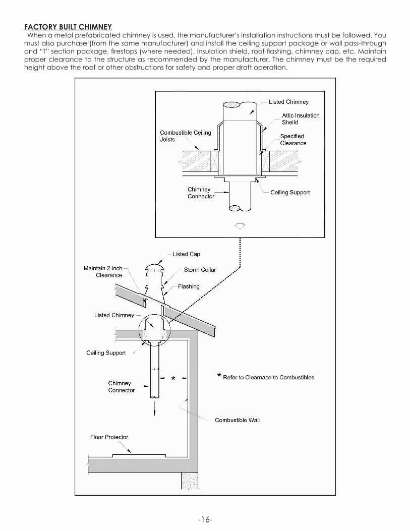
FACTORY BUILT CHIMNEYWhen a metal prefabricated chimney is used, the manufacturer’s installation instructions must be followed. You
must also purchase (from the same manufacturer) and install the ceiling support package or wall pass-through and “T” section package, firestops (where needed), insulation shield, roof flashing, chimney cap, etc. Maintain proper clearance to the structure as recommended by the manufacturer. The chimney must be the required height above the roof or other obstructions for safety and proper draft operation.

-17-
OPERATING THE PRIMARY AND SECONDARY AIR SETTINGSPrimary air- is the driving air supply that feeds the fire in the heater. This air is introduced through the damper in
the feed door to sustain the combustion.Secondary air – is the air supply that is typically introduced above the fire to effectively “re-burn” the smoke
created in the primary combustion before the exhaust gasses exit the stove. This air is preheated before being injected into the heater so it can react with (re-burn) the smoke when they mix.When increasing the amount of primary air supplied to the heater, the secondary should also be increased as
well to ensure a clean burn. Rear Pilot/Tertiary Air – The air that is introduced at the back of the firebox and is to help sustain heat in the
secondary air to help ensure a cleaner burn.Start up: During Start-up the Primary and the Secondary air adjustments should be in the fully open or the “High”
setting positions. This allows for the maximum amount of combustion air during the initial start-up to insure the fastest and cleanest start-up. These settings should remain open until the stove has heated up and an adequate fire has been established. Once the fire is well established, both the primary and the secondary air settings can be adjusted down to the desired heat setting. The primary and the secondary air mix inside the firebox to provide a more efficient and cleaner burn. We encourage that you get to know your stove and how it reacts to adjusting both the primary and the secondary air dampers so that you can achieve the best burn possible for the type of wood and the draft situations in your particular installation.
AIR CONTROL’S
LOW BURN RATE SETTING
FULLY CLOSEDRear Pilot Air Damper
FULLY CLOSEDSecondary Air Damper
FULLY CLOSEDPrimary Air Damper
MAXIMUM BURN RATE SETTING
FULLY OPENEDRear Pilot Air Damper
FULLY OPENEDSecondary Air Damper
FULLY OPENEDPrimary Air Damper
AIR CONTROL’SLow Burn Rate High Burn Rate
Primary Air Damper Fully Closed Fully OpenRear Pilot Air Damper Fully Closed Fully OpenSecondary Air Damper Fully Closed Fully Open
-18-
OperationThe top down method of fire building is recommended for this appliance. After making sure that the stove air
intake controls are fully open (open all three air controls to there maximum setting). Place the largest pieces of wood on the bottom, laid in parallel and close together. Smaller pieces are placed in a second layer, crossways to the first. A third layer of still smaller pieces is laid crossways to the second, this time with some spaces between. Then a fourth layer of loose, small kindling and twisted newspaper sheets tops off the pile.Higher efficiencies and lower emissions generally result when burning air dried seasoned hardwoods, as
compared to softwoods or to green or freshly cut hardwoods.DO NOT BURN:1. Garbage;2. Lawn clippings or yard waste;3. Materials containing rubber, including tires;4. Materials containing plastic;5. Waste petroleum products, paints or paint
thinners, or asphalt products;6. Materials containing asbestos;7. Construction or demolition debris;8. Railroad ties or pressure-treated wood;9. Manure or animal remains;
10. Salt water driftwood or other previously salt water saturated materials;
11. Unseasoned wood; or12. Paper products, cardboard, plywood, or
particleboard. The prohibition against burning these materials does not prohibit the use of fire starters made from paper, cardboard, saw dust, wax and similar substances for the purpose of starting a fire in an affected wood heater.
Burning these materials may result in release of toxic fumes or render the heater ineffective and cause smoke.Dead wood lying on the forest floor should be considered wet, and requires full seasoning time. Standing dead
wood can usually be considered to be about 2/3 seasoned. Splitting and stacking wood before it is stored accelerates drying time. Storing wood on an elevated surface from the ground and under a cover or covered area from rain or snow also accelerates drying time. A good indicator if wood is ready to burn is to check the piece ends. If there are cracks radiating in all directions from the center then the wood should be dry enough to burn. If your wood sizzles in the fire, even though the surface is dry, it may not be fully cured, and should be seasoned longerYour furnace was designed to burn wood only; no other materials should be burned. Waste and other flammable
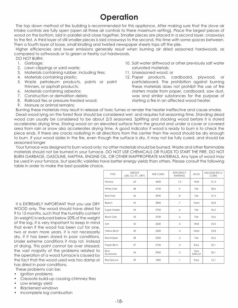
materials should not be burned in your furnace. DO NOT USE CHEMICALS OR FLUIDS TO START THE FIRE. DO NOT BURN GARBAGE, GASOLINE, NAPTHA, ENGINE OIL, OR OTHER INAPPROPRIATE MATERIALS. Any type of wood may be used in your furnace, but specific varieties have better energy yields than others. Please consult the following table in order to make the best possible choice.
TYPE WEIGHT(LBS. CU. FT., DRY) PER CORD EFFICIENCY
RANKING SPLITS MILLIONS BTU’s/CORD
Hickory 63 4500 1.0 Well 31.5
White Oak 48 4100 .9 Fair 28.6
Red Oak 46 3900 .8 Fair 27.4
Beech 45 3800 .7 Hard 26.8
Sugar Maple 44 3700 .6 Fair 26.2
Black Oak 43 3700 .6 Fair 25.6
Ash 42 3600 .5 Well 25.0
Yellow Birch 40 3400 .4 Hard 23.8
Red Maple 38 3200 .3 Fair 22.6
Paper Birch 37 3100 .3 Easy 22.1
Elm/Sycamore 34 2900 .2 Very
Difficult 20.1
Red Spruce 29 1800 .1 Easy 16.1
It is EXTREMELY IMPORTANT that you use DRY WOOD only. The wood should have dried for 9 to 15 months, such that the humidity content (in weight) is reduced below 20% of the weight of the log. It is very important to keep in mind that even if the wood has been cut for one, two or even more years, it is not necessarily dry, if it has been stored in poor conditions. Under extreme conditions it may rot, instead of drying. This point cannot be over stressed; the vast majority of the problems related to the operation of a wood furnace is caused by the fact that the wood used was too damp or has dried in poor conditions.These problems can be:
• Ignition problems• Creosote build-up causing chimney fires• Low energy yield• Blackened windows• Incomplete log combustion
-19-
NOTICE: To minimize the risk of smoke spillage when opening the door with a fire in your furnace, crack the door open no more than 1” and wait for at least 10 seconds before opening it more to allow pressure stabilization inside the furnace.
Smaller pieces of wood will dry faster. All logs exceeding 6” in diameter should be split. The wood should not be stored directly on the ground. Air should circulate through the cord. A 24” to 48” air space should be left between each row of logs, which should be placed in the sunniest location possible. The upper layer of wood should be protected from the elements but not the sides.
TESTING YOUR WOODWhen the furnace is thoroughly warmed, place one piece of split wood (about five inches in diameter) parallel
to the door on the bed of red embers.Adjust all air controls to there maximum settings and close the door. If ignition of the piece is accomplished
within 90 seconds from the time if was placed in the furnace, your wood is correctly dried. If ignition takes longer, your wood is damp.If your wood hisses and water or vapor escapes at the ends of the piece, your wood is soaked or freshly cut.
Do not use this wood in your furnace. Large amounts of creosote could be deposited in your chimney, creating potential conditions for a chimney fire.
THE FIRST FIRESThe fresh paint on your furnace needs to be cured to preserve its quality. Once the fuel charge is properly
ignited, only burn small fires in your furnace for the first four hours of operation. Never open the air control’s more than necessary to achieve a medium burn rate.Make sure that there’s enough air circulation while curing the furnace. DO NOT connect your furnace to the
duct work during this curing process. The odors could be smelled during the 3 or 4 first fires. Never start your furnace outside. You will not be able to see if you are over heating.
LIGHTING YOUR WOOD FURNACE1. Make sure that your furnace has been installed as per the instructions outlined in this manual and the proper
power is supplied to it.2. Open the fuel loading door.3. Note: If there already is a bed of hot/glowing coals in the combustion chamber, proceed directly to the
Preheating step.4. Place several pieces of small dry kindling in the front of the combustion chamber directly on the firebricks.5. Lay a few twists of newspaper over the kindling.6. Lay more dry kindling (crisscrossing) on top of the previous layers and possibly a few more twists of newspaper
if needed.7. Light the lowest newspaper in the stack.Note: In some draft situation you may be required to leave the door cracked no more than ½” only till a fire is
established in the stack No chemical product should be used to light the fire.
PREHEATING YOUR WOOD FURNACE1. Once the kindling is burning well or the glowing coal bed is stirred up, lay 2 or 3 pieces of well-seasoned
cordwood down so that the flame from the kindling fire can circulate around the logs and close the door.Note: You may need to add more kindling to help ignite the cordwood.2. Before loading your furnace fully you will want a well-established fire in the combustion chamber. This
typically takes 15-20 minutes.
HEATING WITH YOUR WOOD FURNACE1. Spread the fire and coals evenly towards the center of the combustion chamber before loading your
furnace fully or adding more wood.2. Avoid overfilling the combustion chamber. Air must be allowed to circulate freely through the upper portion
of the combustion chamber for the stove to perform best. Typically this would mean not to load your furnace more than ¾ of the way up the door opening.
CAUTION: Never alter the “damper slide” or the adjustment range to increase firing for any reason. Doing so could result in heater damage and will void your warranty.
-20-
OPERATIONControlled combustion is the most efficient technique for wood heating because it enables you to select the
type of combustion you want for each given situation. The wood will burn slowly if the wood furnace air intake control’s are adjusted to reduce the oxygen supply in the combustion chamber to a minimum. On the other hand, wood will burn quickly if the air control’s are adjusted to admit a larger quantity of oxygen in the combustion chamber. Real operating conditions may give very different results than those obtained during testing according to the species of wood used, its moisture content, the size and density of the pieces, the length of the chimney, altitude and outside temperature.
RELOADINGOnce you have obtained a good bed of embers, you should reload the unit. In order to do so, open the air
controls to maximum a few seconds prior to opening the furnace’s door. Then proceed by opening the door very slowly. Then bring the red embers to the front of the furnace and reload the unit.For optimal operation of your wood furnace, we recommend you to operate it with a wood load approximately
equivalent to the 3/4 of the height of fire bricks.It is important to note that wood combustion consumes ambient oxygen in the room. In the case of negative
pressure, it is a good idea to allow fresh air in the room, either by opening a window slightly or by installing a fresh air intake system on an outside wall.Creosote - Formation and Need for Removal - When wood is burned slowly, it produces tar and other organic
vapors, which combine with expelled moisture to form creosote. The creosote vapors condense in the relatively cool chimney flue of a slow-burning fire. As a result, creosote residue accumulates on the flue lining. When ignited, this creosote makes an extremely hot fire. The chimney connector and chimney should be inspected at least twice monthly during the heating season to determine if a creosote build-up has occurred. If creosote has accumulated (3mm or more), it should be removed to reduce the risk of a chimney fire.We strongly recommend that you install a magnetic thermometer on your smoke exhaust pipe, approximately
18” above the furnace. This thermometer will indicate the temperature of your gas exhaust fumes within the smoke exhaust system. The ideal temperature for these gases is somewhere between 275°F and 500°F. Below these temperatures, the build-up of creosote is promoted. Above 500 degrees, heat is wasted since a too large quantity is lost into the atmosphere.
TO PREVENT CREOSOTE BUILD UPAlways burn dry wood. This allows clean burns and higher chimney temperatures, therefore less creosote deposit.Leave the air control full open for about 5 min. every time you reload the furnace to bring it back to proper
operating temperatures. The secondary combustion can only take place if the firebox is hot enough.Always check for creosote deposit once every two months and have your chimney cleaned at least once a
year. If a chimney or creosote fire occurs, close all dampers immediately. Wait for the fire to go out and the heater to cool, then inspect the chimney for damage. If no damage results, perform a chimney cleaning to ensure there is no more creosote deposits remaining in the chimney.
ASH DISPOSALWhenever ashes get 3 to 4 inches deep in your firebox or ash pan, and when the fire has burned down and
cooled, remove excess ashes. Leave an ash bed approximately 1 inch deep on the firebox bottom to help maintain a hot charcoal bed.Ashes should be placed in a metal container with a tight-fitting lid. The closed container of ashes should be
placed on a noncombustible floor or on the ground, away from all combustible materials, pending final disposal. The ashes should be retained in the closed container until all cinders have thoroughly cooled.If there is a soot or creosote fire:
• Establish a routine for the storage of fuel, care for the appliance and firing techniques.• Check daily for creosote buildup until experience shows how often cleaning is necessary.• Be aware that the hotter the fire, the less creosote is deposited, and that weekly cleaning can be necessary
in mild weather, even though monthly cleaning can be enough in the coldest months.• Have a clearly understood plan to handle a chimney fire.
WARNINGS:• Never over fire your furnace. If any part of the furnace starts to glow red, over firing is happening. Readjust
the air intake control at a lower setting.• The installation of a log cradle or grates is not recommended in your wood furnace. Build fire directly on
firebrick.• Never put wood above the firebrick lining of the firebox.
-21-
TAMPER WARNINGThis wood heater has a manufacturer-set minimum low burn rate that must not be altered. It is against federal
regulations to alter this setting or otherwise operate this wood heater in a manner inconsistent with operating instructions in this manual.
VISIBLE SMOKEThe amount of visible smoke being produced can be an effective method of determining how efficiently the
combustion process is taking place at the given settings. Visible smoke consist of unburned fuel and moisture leaving your stove. Learn to adjust the air settings of your specific unit to produce the smallest amount of visible smoke. Wood that has not been seasoned properly and has a high wood moisture content will produce excess visible smoke and burn poorly. Use the included moisture meter to insure your wood has a 20% or less moisture content.
EFFICIENCYEfficiencies can be based on either the lower heating value (LHV) or the higher heating value (HHV) of the fuel.
The lower heating value is when water leaves the combustion process as a vapor, in the case of wood stoves the moisture in the wood being burned leaves the stove as a vapor. The higher heating value is when water leaves the combustion process completely condensed. In the case of wood stoves this would assume the exhaust gases are room temperature when leaving the system, and therefore calculations using this heating value consider the heat going up the chimney as lost energy. Therefore, efficiency calculated using the lower heating value of wood will be higher than efficiency calculated using the higher heating value. In the United States all wood stove efficiencies should be calculated using the higher heating value. The best way to achieve optimum efficiencies is to learn the burn characteristic of you appliance and burn well-seasoned wood. Higher burn rates are not always the best heating burn rates; after a good fire is established a lower burn rate may be a better option for efficient heating. A lower burn rate slows the flow of usable heat out of the home through the chimney, and it also consumes less wood.
SMOKE AND CO MONITORSBurning wood naturally produces smoke and carbon monoxide(CO) emissions. CO is a poisonous gas when
exposed to elevated concentrations for extended periods of time. While the modern combustion systems in heaters drastically reduce the amount of CO emitted out the chimney, exposure to the gases in closed or confined areas can be dangerous. Make sure you stove gaskets and chimney joints are in good working order and sealing properly to ensure unintended exposure. It is recommended that you use both smoke and CO monitors in areas having the potential to generate CO.
OVER FIRINGAttempts to achieve heat output rates that exceed heater design specifications can result in permanent
damage to the heater
POWER FAILURE INSTRUCTIONSDO NOT add additional fuel after a power failure, remove all air filters and reduce combustion air to a minimum.
Observe furnace closely until power is restored.
OPERATIONAL TIPSOperational Tips for Good, Efficient, and Clean Combustion
• Get the appliance hot and establish a good coal bed before adjusting to a low burn rate (this may take 30 minutes or more depending on your wood), for an optimal low burn rate, once there is a well established fire in the furnace, close the damper on the door, and the rear pilot air damper completely, and open the secondary air damper to its maximum setting
• Use smaller pieces of wood during start-up and a high burn rate to increase the stove temperature• Be considerate of the environment and only burn dry wood• Burn small, intense fires instead of large, slow burning fires when possible• Learn your appliance’s operating characteristics to obtain optimum performance• Burning unseasoned wet wood only hurts your stoves efficiency and leads to accelerated creosote buildup
in your chimney.
CAUTIONS:• Ashes could contain hot embers even after two days without operating the furnace.• The ash pan can become very hot. Wear gloves to prevent injury.• Never burn the furnace with the ash trap open. This would result in over firing the furnace. Damage to the
furnace and even house fire may result.
-22-
Your wood furnace is a high efficiency furnace and therefore requires little maintenance. It is important to perform a visual inspection of the furnace every time it is emptied, in order to insure that no parts have been damaged, in which case repairs must be performed immediately. Inspect and clean the chimney and connector pipe periodically for creosote buildup or obstructions.
GASKETIt is recommended that you change the door gasket (which makes your furnace door air tight) once a year, in
order to insure good control over the combustion, maximum efficiency and security. To change the door gasket, simply remove the damaged one. Carefully clean the available gasket groove, apply a high temperature silicone sold for this purpose and install the new gasket. You may light up your furnace again approximately 24 hours after having completed this operation. This unit’s feed door uses a 3/4” diameter rope gasket. This unit’s ash door uses a 1/2” diameter rope gasket.
PAINTOnly clean your furnace with a dry soft cloth that will not harm the paint finish. If the paint becomes scratched or
damaged, it is possible to give your wood furnace a brand new look by repainting it with a 1200° F heat resistant paint. For this purpose, simply scrub the surface to be repainted with fine sand paper, clean it properly, and apply thin coats (2) of paint successively.
AIR TUBESThe air tubes assembled in this unit are designed to provide an accurate mix of secondary air to insure the
highest efficiency. Any damage or deterioration of these tubes may reduce the efficiency of combustion. The air tubes are held in position by either screws or snap pins. Locate these to either side of the tube and remove to allow the tube to be removed and replaced.
WARNING: Never operate the furnace without a gasket or with a broken one. Damage to the furnace or even house fire may result.
Maintenance
ATTENTION: This wood heater needs periodic inspection and repair for proper operation. It is against federal regulations to operate this wood heater in a manner inconsistent with operating instructions in this manual.
-23-
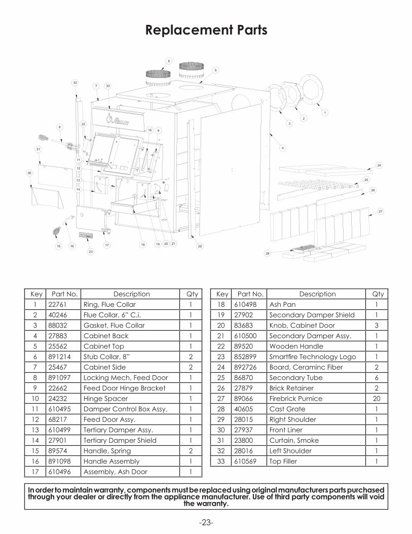
In order to maintain warranty, components must be replaced using original manufacturers parts purchased through your dealer or directly from the appliance manufacturer. Use of third party components will void
the warranty.
Key Part No. Description Qty1 22761 Ring, Flue Collar 12 40246 Flue Collar, 6” C.i. 13 88032 Gasket, Flue Collar 14 27883 Cabinet Back 15 25562 Cabinet Top 16 891214 Stub Collar, 8” 27 25467 Cabinet Side 28 891097 Locking Mech, Feed Door 19 22662 Feed Door Hinge Bracket 1
10 24232 Hinge Spacer 111 610495 Damper Control Box Assy. 112 68217 Feed Door Assy. 113 610499 Tertiary Damper Assy. 114 27901 Tertiary Damper Shield 115 89574 Handle, Spring 216 891098 Handle Assembly 117 610496 Assembly, Ash Door 1
Replacement Parts
1
2
29
3
4
2120191817
23
1615
14
13
5
6
228
32337
31
3012
11
10 9
24
25
26
27
28
Key Part No. Description Qty18 610498 Ash Pan 119 27902 Secondary Damper Shield 120 83683 Knob, Cabinet Door 321 610500 Secondary Damper Assy. 122 89520 Wooden Handle 123 852899 Smartfire Technology Logo 124 892726 Board, Ceraminc Fiber 225 86870 Secondary Tube 626 27879 Brick Retainer 227 89066 Firebrick Pumice 2028 40605 Cast Grate 129 28015 Right Shoulder 130 27937 Front Liner 131 23800 Curtain, Smoke 132 28016 Left Shoulder 133 610569 Top Filler 1
-24-
1
2
4
5
6
9
8
7
10
113
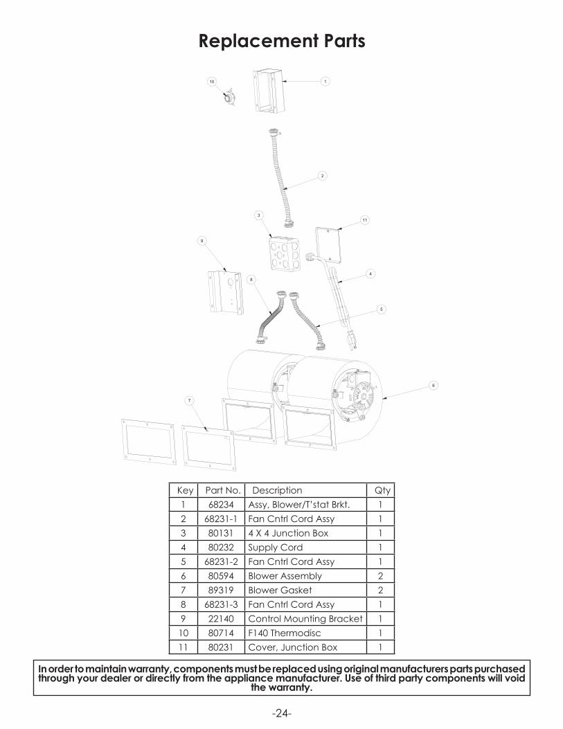
Key Part No. Description Qty1 68234 Assy, Blower/T’stat Brkt. 12 68231-1 Fan Cntrl Cord Assy 13 80131 4 X 4 Junction Box 14 80232 Supply Cord 15 68231-2 Fan Cntrl Cord Assy 16 80594 Blower Assembly 27 89319 Blower Gasket 28 68231-3 Fan Cntrl Cord Assy 19 22140 Control Mounting Bracket 1
10 80714 F140 Thermodisc 111 80231 Cover, Junction Box 1
In order to maintain warranty, components must be replaced using original manufacturers parts purchased through your dealer or directly from the appliance manufacturer. Use of third party components will void
the warranty.
Replacement Parts
-25-
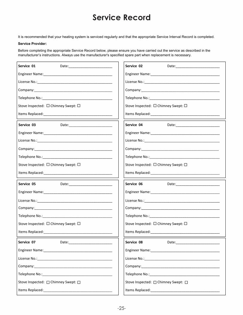
Service 01 Date:________________________
Engineer Name:_____________________________________
Company:__________________________________________
Telephone No.:______________________________________
Stove Inspected: Chimney Swept:
Items Replaced:____________________________________
It is recommended that your heating system is serviced regularly and that the appropriate Service Interval Record is completed.
Service Provider:
Before completing the appropriate Service Record below, please ensure you have carried out the service as described in the manufacturer’s instructions. Always use the manufacturer's specified spare part when replacement is necessary.
Service 02 Date:________________________
Engineer Name:_____________________________________
License No.:________________________________________ License No.:_______________________________________
Company:_________________________________________
Telephone No.:______________________________________
Stove Inspected: Chimney Swept:
Items Replaced:____________________________________
Service 03 Date:________________________
Engineer Name:_____________________________________
Company:__________________________________________
Telephone No.:______________________________________
Stove Inspected: Chimney Swept:
Items Replaced:____________________________________
Service 04 Date:________________________
Engineer Name:_____________________________________
Company:________________________________________
Telephone No.:______________________________________
Stove Inspected: Chimney Swept:
Items Replaced:____________________________________
Service 05 Date:________________________
Engineer Name:_____________________________________
Company:__________________________________________
Telephone No.:______________________________________
Stove Inspected: Chimney Swept:
Items Replaced:____________________________________
Service 06 Date:_______________________
Engineer Name:_____________________________________
Company:_________________________________________
Telephone No.:______________________________________
Stove Inspected: Chimney Swept:
Items Replaced:____________________________________
Service 07 Date:________________________
Engineer Name:_____________________________________
Company:__________________________________________
Telephone No.:______________________________________
Stove Inspected: Chimney Swept:
Items Replaced:____________________________________
Service 08 Date:_______________________
Engineer Name:_____________________________________
Company:_________________________________________
Telephone No.:______________________________________
Stove Inspected: Chimney Swept:
Items Replaced:____________________________________
License No.:_______________________________________ License No.:_______________________________________
License No.:_______________________________________ License No.:_______________________________________
License No.:_______________________________________ License No.:_______________________________________
Service Record
-26-
Limited WarrantyWarm Air Furnace
The operation of this heater in a manner inconsistent with the owner’s manual will void the warranty and is also against federal regulations.
United States Stove Company warrants to the original purchaser its heating products against premature failure of any component due to workmanship, quality, or materials as follows:
TIME PERIOD:Firebox ...................................................................................................................................... Three YearsFlue Collar - if equipped .............................................................................................................. Three YearsAll Doors (Feed and Ash)............................................................................................................. Three YearsCabinet and Trim ........................................................................................................................ Three YearsBi-Metal Thermostat ......................................................................................................................Two YearsCast Iron Components, Steel Liners and Retainers ............................................................................ One YearGaskets ......................................................................................................................................... One YearAll Electrical Components (Including Blower) - if equipped ................................................................. One YearPaint and Finish .............................................................................................................................. One Year
CLAIM PROCEDUREAny defects should be reported to United States Stove Company or its dealer and/or distributor giving descriptions and pertinent data, including proof or purchase which will be returned upon request.Providing the heater has been installed and used in accordance with the Owners Manual supplied with the heater, United States Stove Company will either:1) Replace the defective part free of charge2) Replace the heater free of charge3) Where the defect is of a cosmetic (non-functional) nature, United States Stove Company will bear reasonable expense to refurbish the heater,
including such items as welding, painting, and incidental labor. A “Reasonable” expense is defi ned by terms of this warranty as $30.00/hour with full refund for any purchase of parts.
NOT COVEREDSpecifi cally not covered under terms of this limited warranty or any other warranty are problems relating to smoking or creosote. Smoking is attributable to inadequate draft due to the design or installation of the fl ue system or installation of the heater itself. Creosote formation is largely attributable to improper operation of the unit and/or draft as mentioned above. Also, not covered are:1) Removal and re-installation cost.2) Service calls to diagnose trouble (unless authorized in writing by the manufacturer, distributor, or dealer).3) Painted surfaces, brass or brass-colored surfaces.4) Damage or defect caused by improper installation, accidents, misuse, abuse (including overfi ring) or alteration.5) Transportation or shipping costs.
LIMITATIONS AND EXCLUSIONS1) United States Stove Company shall not be liable for incidental, consequential, special, or contingent damages anyone might suffer as a result of their
breach of this written warranty or any implied warranty.2) Should the heater be replaced by United States Stove Company “free of charge”, all further warranty obligations are thereby met.3) Parts and/or service replacements made under the terms of this warranty are warranted only for the remaining period of the original heater warranty.4) Without specifi c written exclusionary waivers, no one has authority to add to or vary this limited warranty, or to create for United States Stove
Company any further obligation of liability in connection with this heater or any other applicable accessory. Any further warranty implication applicable to this heater or any applicable accessory is limited in duration to the same time period as the original statement in the above schedule.
YOUR DUTIES1) This heater, including all applicable accessories, must be installed and operated in accordance with local authorities having jurisdiction and the
instructions furnished with the Owners Manual.2) You should keep as permanent record your proof of purchase (or canceled check or invoice).
PROBLEM/RESOLUTION1) As purchaser, you must fi rst contact the dealer and/or distributor from whom you purchased your heater.2) If within a reasonable period of time you do not receive satisfactory service from the distributor and/or dealer, write or call United States Stove
Company, Customer Service Department, including complete details of the problem and/or problems you are experiencing, details of your installation, your proof of purchase, and the heater serial number or test agency code number.
WARRANTORThe warrantor of record is United States Stove Company, PO Box 151, 227 Industrial Park Road, South Pittsburg, Tennessee 37380.
Phone number 800-750-2723 • Website www.usstove.com
NOTEThis warranty gives you specifi c legal rights; and, you may also have other rights which vary from state to state. Register your product on line at
www.usstove.com. Save your receipt with your records for any claims.
IMPORTANTWe congratulate you on your selection of United States Stove Company and its products. As the oldest solid fuel manufacturer in the United States (since 1869), the United States Stove Company is very proud of its products, service, employees, and satisfi ed customers. We would like to hear from you if you are not satisfi ed with the manner in which you have been handled by our distributor, dealer, representative, customer service
department, parts department, or sales department. Please reach out to us by using any of the contact information listed above.
85815J

Notes
How to order Replacement Parts
This manual will help you obtain efficient, dependable service from your stove, and enable you to order repair parts correctly.
Keep this manual in a safe place for future reference.When writing, always give the full model number which is on the nameplate attached to the stove.
When ordering repair parts, always give the following information as shown in this list:
1. The part number __________________________________________________________________________________
2. The part description _______________________________________________________________________________
3. The model number ________________________________________________________________________________
4. The serial number _________________________________________________________________________________
United States Stove Company227 Industrial Park RoadSouth Pittsburg, TN 37380
(800) 750-2723www.usstove.com