Embed Size (px)
Citation preview
owner's manual BVM32 Series
Vertical Multistage Pumps
© 2013 Pentair, Ltd. All Rights Reserved. BE780 (Rev. 02/12/13)
269 TRiLLium DRivE, KiTchEnER, OnTARiO, cAnADA n2G 4W5Ph: 888-363-7867
293 WRiGhT STREET, DELAvAn, Wi 53115 WWW.BERKELEYPumPS.cOmPh: 888-237-5353
INSTALLATION AND OPERATING INSTRUCTIONS
Single and Three Phase 60 cycle
record the following information from the motor and pump nameplates for future reference:
Pump model no.
Bill of material no.
motor model no.
motor serial no.
H.P. Volts/Hz/Ph
rated amp Draw
5006 0405 ASB
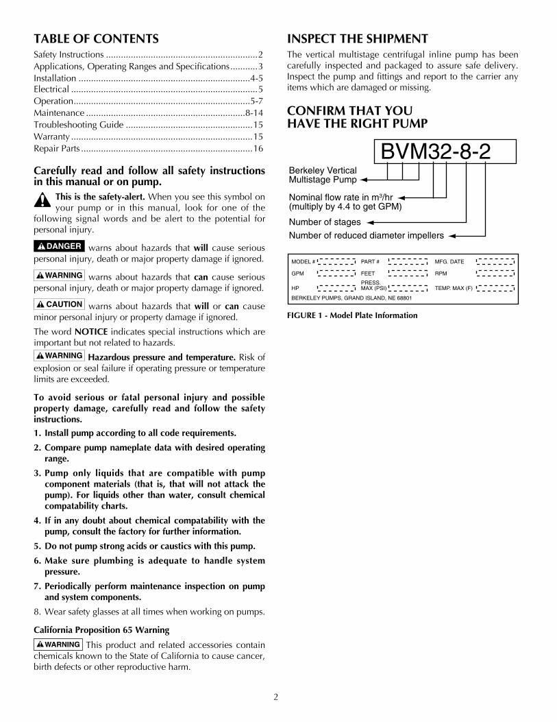
TABLE OF CONTENTS Safety Instructions .............................................................2Applications, Operating Ranges and Specifications ...........3Installation .....................................................................4-5Electrical ...........................................................................5Operation .......................................................................5-7Maintenance ................................................................8-14Troubleshooting Guide ...................................................15Warranty .........................................................................15Repair Parts .....................................................................16
Carefully read and follow all safety instructions in this manual or on pump.
This is the safety-alert. When you see this symbol on your pump or in this manual, look for one of the
following signal words and be alert to the potential for personal injury.
warns about hazards that will cause serious personal injury, death or major property damage if ignored.
warns about hazards that can cause serious personal injury, death or major property damage if ignored.
warns about hazards that will or can cause minor personal injury or property damage if ignored.
The word NOTICE indicates special instructions which are important but not related to hazards.
Hazardous pressure and temperature. Risk of explosion or seal failure if operating pressure or temperature limits are exceeded.
To avoid serious or fatal personal injury and possible property damage, carefully read and follow the safety instructions.
1. Install pump according to all code requirements.
2. Compare pump nameplate data with desired operating range.
3. Pump only liquids that are compatible with pump component materials (that is, that will not attack the pump). For liquids other than water, consult chemical compatability charts.
4. If in any doubt about chemical compatability with the pump, consult the factory for further information.
5. Do not pump strong acids or caustics with this pump.
6. Make sure plumbing is adequate to handle system pressure.
7. Periodically perform maintenance inspection on pump and system components.
8. Wear safety glasses at all times when working on pumps.
California Proposition 65 Warning
This product and related accessories contain chemicals known to the State of California to cause cancer, birth defects or other reproductive harm.
INSPECT THE SHIPMENTThe vertical multistage centrifugal inline pump has been carefully inspected and packaged to assure safe delivery. Inspect the pump and fittings and report to the carrier any items which are damaged or missing.
CONFIRM THAT YOU HAVE THE RIGHT PUMP
2
BVM32-8-2Berkeley VerticalMultistage Pump
Nominal flow rate in m3/hr(multiply by 4.4 to get GPM)
Number of stages
Number of reduced diameter impellers 4180 0502 32
MODEL #
GPM
HP
PART #
FEET
PRESS. MAX (PSI)
MFG. DATE
RPM
TEMP. MAX (F)
BERKELEY PUMPS, GRAND ISLAND, NE 68801
FIGURE 1 - Model Plate Information
3
APPLICATIONS AND OPERATING RANGESBerkeley multistage in-line centrifugal pumps are designed for liquid transfer, circulation, and pressure boosting of hot or cold clean water or other thin, non-explosive liquids, not containing solid particles or fibers, which will not chemically attack the pump materials.
Typical applications include:
• Municipalwatersupplyandpressureboosting
• Boilerfeedandcondensatesystems
• Coolingwatersystems
• Irrigation
• Firefighting
BVM32 SPECIFICATIONSMaximum Operating Temperature ............................250°F
Liquid Temperature Range ........................+5°Fto+250°F
Minimum Suction Pipe Size ........ 2-1/2" Nominal Diameter
Minimum Pumping Rate: Upto175°F .......................................................15 GPM
175°Fto250°F ..................................................35 GPM
Maximum Ambient Temperature ...................104°F(40°C)
Liquid Temperature Range .............................5°Fto250°F (-15°Cto+121°C)
Maximum Permissible Operating Pressure .............. 435 psiNOTE: The pump’s inlet pressure plus the discharge pressure when the pump is running against a closed valve must always be lower than the “Maximum Permissible Operating Pressure”.
Electrical Data: ..................................See Motor Nameplate
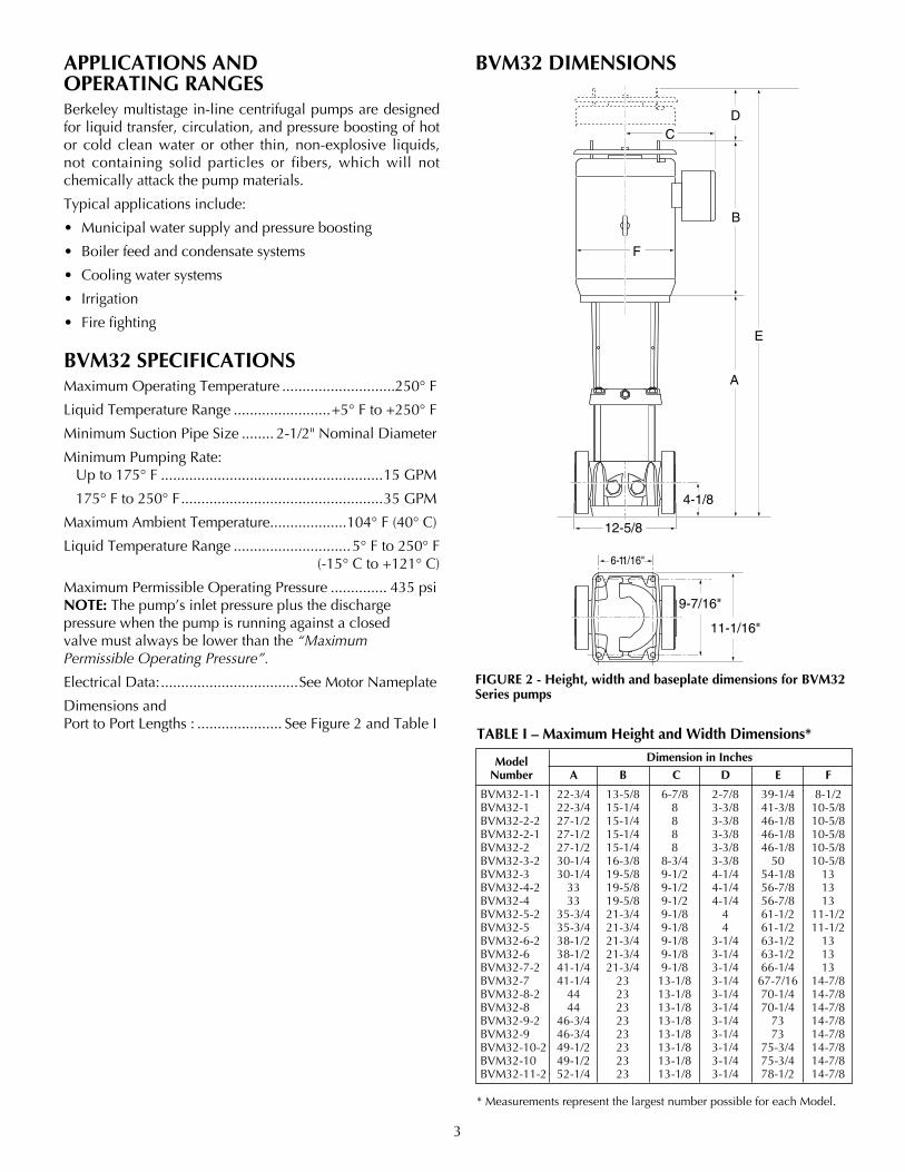
Dimensions and Port to Port Lengths : ..................... SeeFigure2andTableI
BVM32 DIMENSIONS
E
B
D
A
C
4-1/8
12-5/8
9-7/16"
11-1/16"
F
4957 0405FIGURE 2 - Height, width and baseplate dimensions for BVM32 Series pumps
* Measurements represent the largest number possible for each Model.
TABLE I – Maximum Height and Width Dimensions*
Model Dimension in Inches
Number A B C D E F
BVM32-1-1 22-3/4 13-5/8 6-7/8 2-7/8 39-1/4 8-1/2 BVM32-1 22-3/4 15-1/4 8 3-3/8 41-3/8 10-5/8 BVM32-2-2 27-1/2 15-1/4 8 3-3/8 46-1/8 10-5/8 BVM32-2-1 27-1/2 15-1/4 8 3-3/8 46-1/8 10-5/8 BVM32-2 27-1/2 15-1/4 8 3-3/8 46-1/8 10-5/8 BVM32-3-2 30-1/4 16-3/8 8-3/4 3-3/8 50 10-5/8 BVM32-3 30-1/4 19-5/8 9-1/2 4-1/4 54-1/8 13 BVM32-4-2 33 19-5/8 9-1/2 4-1/4 56-7/8 13 BVM32-4 33 19-5/8 9-1/2 4-1/4 56-7/8 13 BVM32-5-2 35-3/4 21-3/4 9-1/8 4 61-1/2 11-1/2 BVM32-5 35-3/4 21-3/4 9-1/8 4 61-1/2 11-1/2 BVM32-6-2 38-1/2 21-3/4 9-1/8 3-1/4 63-1/2 13 BVM32-6 38-1/2 21-3/4 9-1/8 3-1/4 63-1/2 13 BVM32-7-2 41-1/4 21-3/4 9-1/8 3-1/4 66-1/4 13 BVM32-7 41-1/4 23 13-1/8 3-1/4 67-7/16 14-7/8 BVM32-8-2 44 23 13-1/8 3-1/4 70-1/4 14-7/8 BVM32-8 44 23 13-1/8 3-1/4 70-1/4 14-7/8 BVM32-9-2 46-3/4 23 13-1/8 3-1/4 73 14-7/8 BVM32-9 46-3/4 23 13-1/8 3-1/4 73 14-7/8 BVM32-10-2 49-1/2 23 13-1/8 3-1/4 75-3/4 14-7/8 BVM32-10 49-1/2 23 13-1/8 3-1/4 75-3/4 14-7/8 BVM32-11-2 52-1/4 23 13-1/8 3-1/4 78-1/2 14-7/8
4
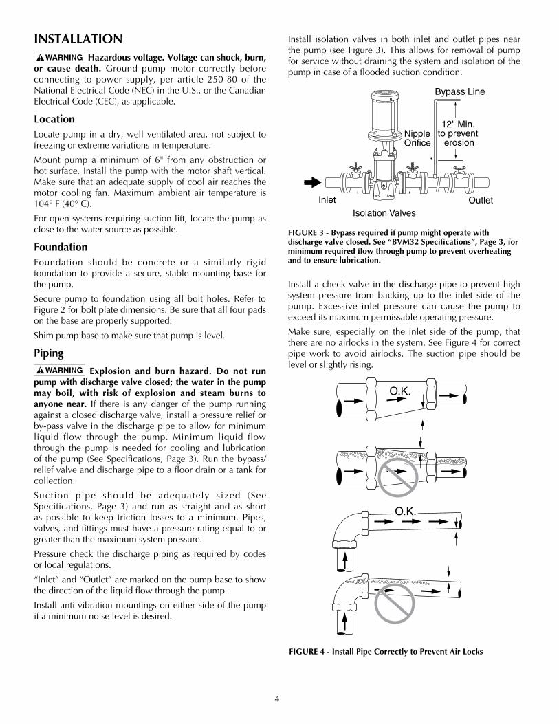
INSTALLATION
Hazardous voltage. Voltage can shock, burn, or cause death. Ground pump motor correctly before connecting to power supply, per article 250-80 of the NationalElectricalCode(NEC)intheU.S.,ortheCanadianElectricalCode(CEC),asapplicable.
LocationLocate pump in a dry, well ventilated area, not subject to freezing or extreme variations in temperature.
Mount pump a minimum of 6" from any obstruction or hot surface. Install the pump with the motor shaft vertical. Make sure that an adequate supply of cool air reaches the motor cooling fan. Maximum ambient air temperature is 104°F(40°C).
Foropensystemsrequiringsuctionlift,locatethepumpasclose to the water source as possible.
FoundationFoundation should be concrete or a similarly rigidfoundation to provide a secure, stable mounting base for the pump.
Secure pump to foundation using all bolt holes. Refer to Figure2forboltplatedimensions.Besurethatallfourpadson the base are properly supported.
Shim pump base to make sure that pump is level.
Piping
Explosion and burn hazard. Do not run pump with discharge valve closed; the water in the pump may boil, with risk of explosion and steam burns to anyone near. If there is any danger of the pump running against a closed discharge valve, install a pressure relief or by-pass valve in the discharge pipe to allow for minimum liquid flow through the pump. Minimum liquid flow through the pump is needed for cooling and lubrication of thepump (SeeSpecifications,Page3).Run thebypass/relief valve and discharge pipe to a floor drain or a tank for collection.
Suction pipe should be adequately sized (SeeSpecifications, Page 3) and run as straight and as shortas possible to keep friction losses to a minimum. Pipes, valves, and fittings must have a pressure rating equal to or greater than the maximum system pressure.
Pressure check the discharge piping as required by codes or local regulations.
“Inlet” and “Outlet” are marked on the pump base to show the direction of the liquid flow through the pump.
Install anti-vibration mountings on either side of the pump if a minimum noise level is desired.
Install isolation valves in both inlet and outlet pipes near thepump(seeFigure3).Thisallows for removalofpumpfor service without draining the system and isolation of the pump in case of a flooded suction condition.
Install a check valve in the discharge pipe to prevent high system pressure from backing up to the inlet side of the pump. Excessive inlet pressure can cause the pump to exceed its maximum permissable operating pressure.
Make sure, especially on the inlet side of the pump, that therearenoairlocksinthesystem.SeeFigure4forcorrectpipe work to avoid airlocks. The suction pipe should be level or slightly rising.
FIGURE 3 - Bypass required if pump might operate with discharge valve closed. See “BVM32 Specifications”, Page 3, for minimum required flow through pump to prevent overheating and to ensure lubrication.
4218 0702
Inlet Outlet
NippleOrifice
Bypass Line
12" Min. to prevent
erosion
Isolation Valves
O.K.
3347 1198
O.K.
FIGURE 4 - Install Pipe Correctly to Prevent Air Locks
5
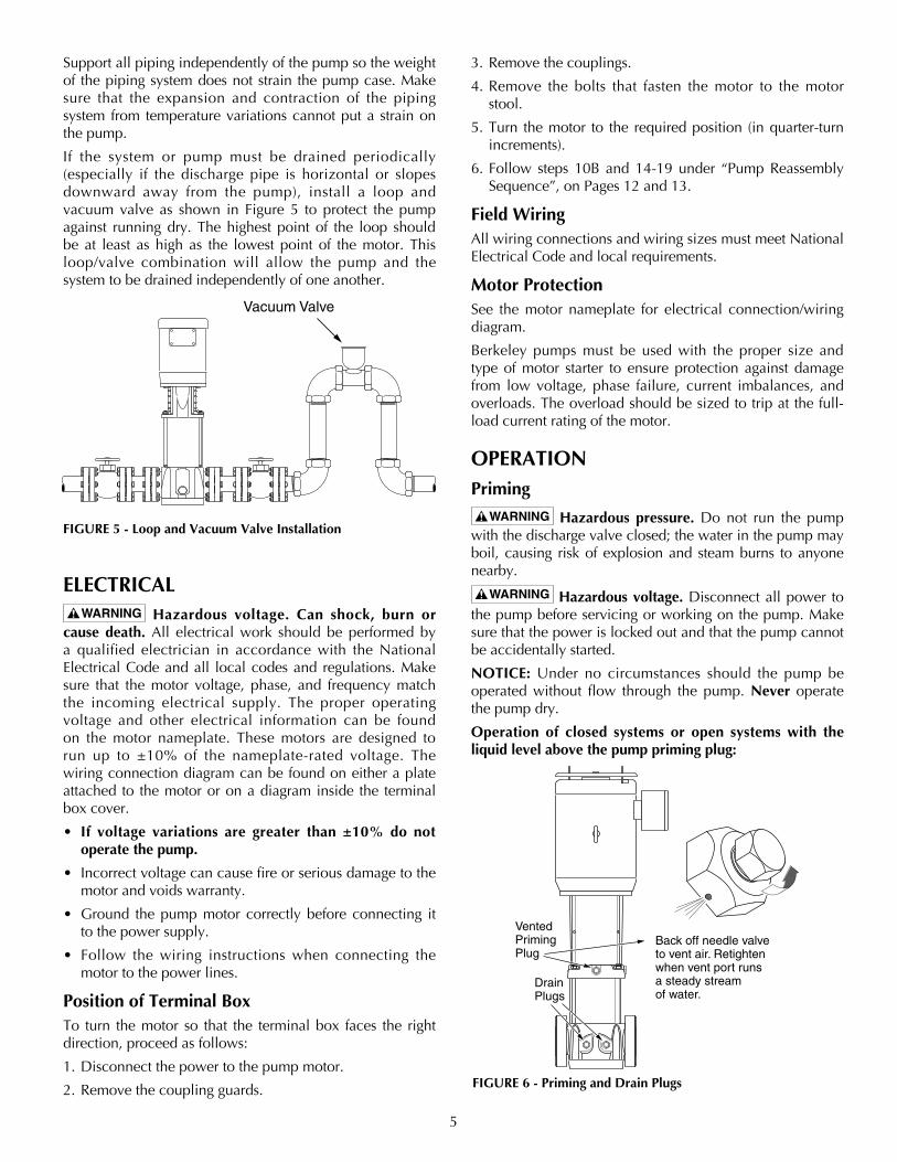
Support all piping independently of the pump so the weight of the piping system does not strain the pump case. Make sure that the expansion and contraction of the piping system from temperature variations cannot put a strain on the pump.
If the system or pump must be drained periodically (especially if the discharge pipe is horizontal or slopesdownward away from the pump), install a loop andvacuumvalve as shown in Figure 5 to protect the pumpagainst running dry. The highest point of the loop should be at least as high as the lowest point of the motor. This loop/valve combination will allow the pump and the system to be drained independently of one another.
ELECTRICAL
Hazardous voltage. Can shock, burn or cause death. All electrical work should be performed by a qualified electrician in accordance with the National Electrical Code and all local codes and regulations. Make sure that the motor voltage, phase, and frequency match the incoming electrical supply. The proper operating voltage and other electrical information can be found on the motor nameplate. These motors are designed to run up to ±10% of the nameplate-rated voltage. The wiring connection diagram can be found on either a plate attached to the motor or on a diagram inside the terminal box cover.
• If voltage variations are greater than ±10% do not operate the pump.
• Incorrectvoltagecancausefireorseriousdamagetothemotor and voids warranty.
• Ground thepumpmotor correctlybefore connecting itto the power supply.
• Follow thewiring instructionswhen connecting themotor to the power lines.
Position of Terminal BoxTo turn the motor so that the terminal box faces the right direction, proceed as follows:
1. Disconnect the power to the pump motor.
2. Remove the coupling guards.
3. Remove the couplings.
4. Remove the bolts that fasten the motor to the motor stool.
5.Turn themotor to the requiredposition (inquarter-turnincrements).
6.Follow steps 10Band14-19under “PumpReassemblySequence”, on Pages 12 and 13.
Field WiringAll wiring connections and wiring sizes must meet National Electrical Code and local requirements.
Motor ProtectionSee the motor nameplate for electrical connection/wiring diagram.
Berkeley pumps must be used with the proper size and type of motor starter to ensure protection against damage from low voltage, phase failure, current imbalances, and overloads. The overload should be sized to trip at the full-load current rating of the motor.
OPERATIONPriming
Hazardous pressure. Do not run the pump with the discharge valve closed; the water in the pump may boil, causing risk of explosion and steam burns to anyone nearby.
Hazardous voltage. Disconnect all power to the pump before servicing or working on the pump. Make sure that the power is locked out and that the pump cannot be accidentally started.
NOTICE: Under no circumstances should the pump be operated without flow through the pump. Never operate the pump dry.
Operation of closed systems or open systems with the liquid level above the pump priming plug:
3346 1198
Vacuum Valve
FIGURE 5 - Loop and Vacuum Valve Installation
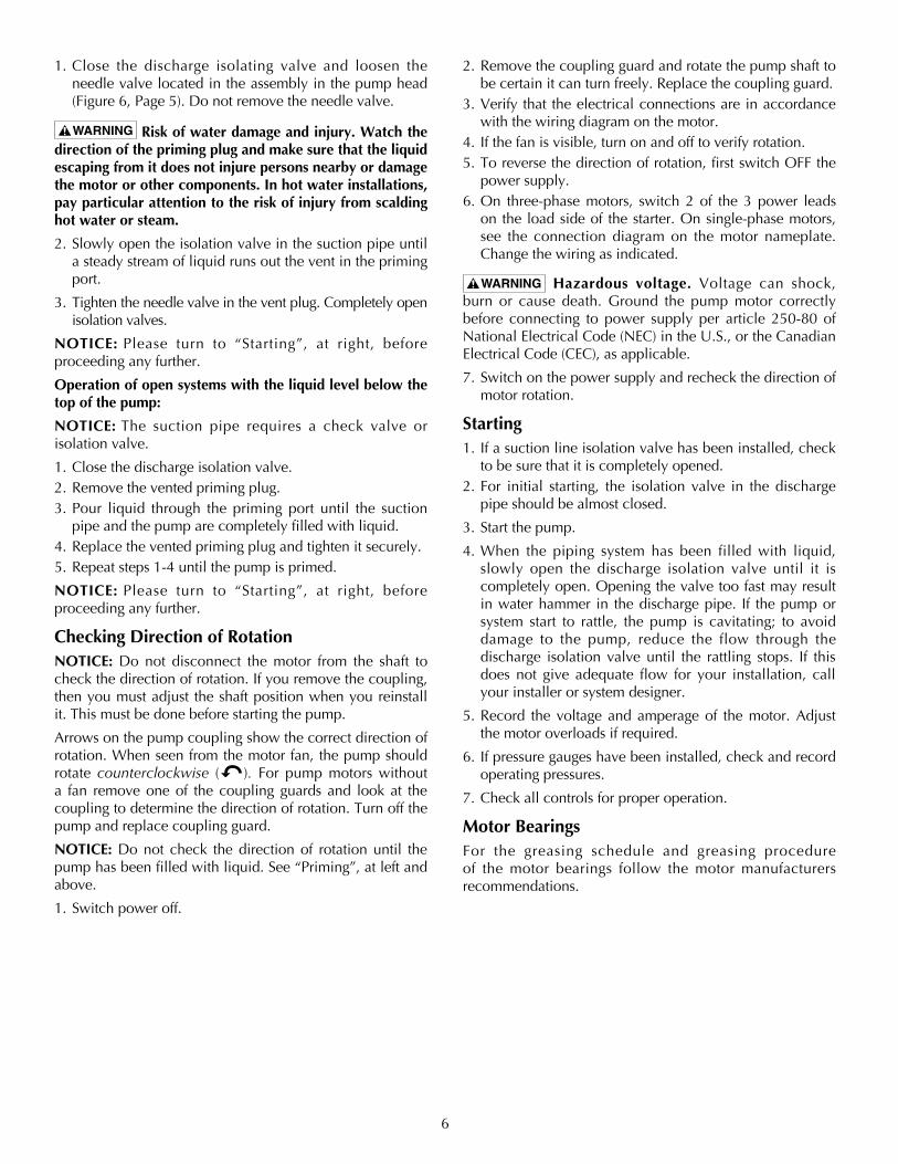
VentedPrimingPlug
DrainPlugs
Back off needle valve to vent air. Retighten when vent port runs a steady stream of water.
FIGURE 6 - Priming and Drain Plugs
6
1. Close the discharge isolating valve and loosen the needle valve located in the assembly in the pump head (Figure6,Page5).Donotremovetheneedlevalve.
Risk of water damage and injury. Watch the direction of the priming plug and make sure that the liquid escaping from it does not injure persons nearby or damage the motor or other components. In hot water installations, pay particular attention to the risk of injury from scalding hot water or steam.
2. Slowly open the isolation valve in the suction pipe until a steady stream of liquid runs out the vent in the priming port.
3. Tighten the needle valve in the vent plug. Completely open isolation valves.
NOTICE: Please turn to “Starting”, at right, before proceeding any further.
Operation of open systems with the liquid level below the top of the pump:
NOTICE: The suction pipe requires a check valve or isolation valve.
1. Close the discharge isolation valve.2. Remove the vented priming plug.3. Pour liquid through the priming port until the suction
pipe and the pump are completely filled with liquid.4. Replace the vented priming plug and tighten it securely.5. Repeat steps 1-4 until the pump is primed.
NOTICE: Please turn to “Starting”, at right, before proceeding any further.
Checking Direction of RotationNOTICE: Do not disconnect the motor from the shaft to check the direction of rotation. If you remove the coupling, then you must adjust the shaft position when you reinstall it. This must be done before starting the pump.
Arrows on the pump coupling show the correct direction of rotation. When seen from the motor fan, the pump should rotate counterclockwise ( ). For pumpmotorswithouta fan remove one of the coupling guards and look at the coupling to determine the direction of rotation. Turn off the pump and replace coupling guard.
NOTICE: Do not check the direction of rotation until the pump has been filled with liquid. See “Priming”, at left and above.
1. Switch power off.
2. Remove the coupling guard and rotate the pump shaft to be certain it can turn freely. Replace the coupling guard.
3. Verify that the electrical connections are in accordance with the wiring diagram on the motor.
4. If the fan is visible, turn on and off to verify rotation.5.Toreversethedirectionofrotation,firstswitchOFFthe
power supply.6. On three-phase motors, switch 2 of the 3 power leads
on the load side of the starter. On single-phase motors, see the connection diagram on the motor nameplate. Change the wiring as indicated.
Hazardous voltage. Voltage can shock, burn or cause death. Ground the pump motor correctly before connecting to power supply per article 250-80 of NationalElectricalCode(NEC)intheU.S.,ortheCanadianElectricalCode(CEC),asapplicable.
7. Switch on the power supply and recheck the direction of motor rotation.
Starting1. If a suction line isolation valve has been installed, check
to be sure that it is completely opened.2.For initial starting, the isolation valve in the discharge
pipe should be almost closed.
3. Start the pump.
4. When the piping system has been filled with liquid, slowly open the discharge isolation valve until it is completely open. Opening the valve too fast may result in water hammer in the discharge pipe. If the pump or system start to rattle, the pump is cavitating; to avoid damage to the pump, reduce the flow through the discharge isolation valve until the rattling stops. If this does not give adequate flow for your installation, call your installer or system designer.
5. Record the voltage and amperage of the motor. Adjust the motor overloads if required.
6. If pressure gauges have been installed, check and record operating pressures.
7. Check all controls for proper operation.
Motor BearingsFor the greasing schedule and greasing procedureof the motor bearings follow the motor manufacturers recommendations.

7
Calculating Minimum Inlet Pressure:Minimum inlet pressure is required to avoid cavitation in the pump and is calculated as follows:
H = Pb - NPSHR - Hf - Hv - HsH=MinimumInletPressureinFeetofHeadPb=BarometricPressureinFeet1Bar=29.53inchesofMercury(Hg)1PSI=2.31FtofHead1Bar=33.5Ft.ofHeadNPSHR = Net Positive suction head required. To be read from theNPSHRcurve, Figure 7, at the highest flow thepump will be delivering.Hf=FrictionLossinsuctionpipeinftofheadHv=Vaporpressureinfeetofhead(SeeTableII).Hs = A safety margin of 1.64 ft of head
Example for BVM32:If: Flow=145GPM Pb = 1 Bar = 29.53 Inches of Mercury*
(ConvertfromBartoFeetofHead) 1 Inch of mercury = 1.13’ feet of water T=100°F NPSHR=10’(SeeFigure7) Hf = 10’ of 2-1/2" Steel Pipe @ 14.5’ of loss per
100’ofPipe(Hf=14.5’/10=1.45’) Hv=2.195’(fromTableII) Hs=1.64’(safetyfactorfromabove)Then: H = 33.5’* - NPSHR - Hf - Hv - Hs H = 33.5’ - 10’ - 1.45’ - 2.195’ - 1.64 = 18.215’ H = 18.215’ = Minimum Inlet Pressure *1Bar=14.5PSIx2.31FtofHead=33.5’
FF
D
F
D
DB
F
DD
DDD
DB
DB
F
DD
D
DD
D
DB
DB
F
DD
D
DD
DD
DB
DB
F
DD
DD
DDDD
DB
DB
F
D
DDB
F
D
DD
DB
F
D
DDD
DB
F
D
DDD
DDB
1234567891011
123456789
10
12345678
123456
1234
12
Type DB and D Stages
Type DB and D Bowl
Type F Stage
Type F Bowl (note slots for straps)
Collet (D, DB, F)
Locknut (D, DB, F)
Bearing (DB Only)
Impeller
5007 0405
5
10
15
20
30
25
6000
80 100 120 140 160 180 200 220
NP
SH
R in
Fee
t
Flow in GPM
BVM 32
3354 1298 BVM32FIGURE 7 - Net Positive Suction Head Requirement (NPSHR)
FIGURE 8 - Stack Assembly Order
Temperature Vapor Pressure Absolute Pressure in °F (°C) in PSIA (kPa) in Feet (M) of Water
32 (0) 0.089(.61) 0.205(.062)
40(4.4) 0.122(.84) 0.281(.086)
60(15.6) 0.256(1.77) 0.592(.180)
80(26.7) 0.507(3.50) 1.172(.358)
100(37.8) 0.95(6.55) 2.195(.669)
120(48.9) 1.695(11.69) 3.914(1.193)
140(60.0) 2.892(19.94) 6.681(2.036)
160(71.1) 4.745(32.72) 10.961(3.341)
180(82.2) 7.515(51.84) 17.36(5.291)
200(93.3) 11.529(79.49) 26.632(8.117)
210(98.9) 14.125(97.39) 32.629(9.945)
212 (100) 14.698(101.34) 33.952(10.349)
220(104.4) 17.188(118.51) 39.704(12.102)
230(110.0) 20.78(143.28) 48.002(14.631)
240(115.6) 24.97(172.17) 57.681(17.581)
248 (120.0) 28.79(188.51) 66.505(20.271)
TABLE II – Vapor Pressure of Water
8
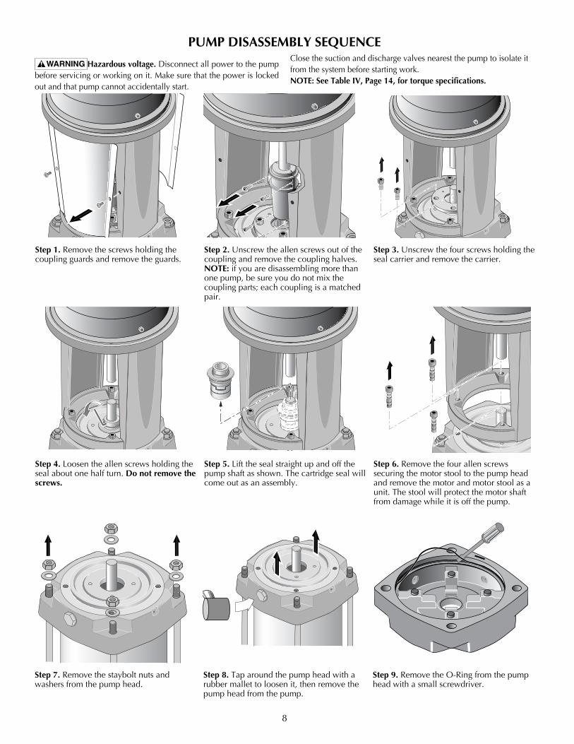
Step 1. Remove the screws holding the coupling guards and remove the guards.
4959 0405Step 2. Unscrew the allen screws out of the coupling and remove the coupling halves. NOTE: if you are disassembling more than one pump, be sure you do not mix the coupling parts; each coupling is a matched pair.
4960 0405Step 3. Unscrew the four screws holding the seal carrier and remove the carrier.
4961 0405Step 4. Loosen the allen screws holding the seal about one half turn. Do not remove the screws.
4962 0405Step 5. Lift the seal straight up and off the pump shaft as shown. The cartridge seal will come out as an assembly.
4963 0405Step 6. Remove the four allen screws securing the motor stool to the pump head and remove the motor and motor stool as a unit. The stool will protect the motor shaft from damage while it is off the pump.
4964 0405Step 7. Remove the staybolt nuts and washers from the pump head.
Hazardous voltage. Disconnect all power to the pump before servicing or working on it. Make sure that the power is locked out and that pump cannot accidentally start.
Close the suction and discharge valves nearest the pump to isolate it from the system before starting work.NOTE: See Table IV, Page 14, for torque specifications.
PUMP DISASSEMBLY SEqUENCE
Step 8. Tap around the pump head with a rubber mallet to loosen it, then remove the pump head from the pump.
4965 0405
Step 9. Remove the O-Ring from the pump head with a small screwdriver.
4966 0405
9
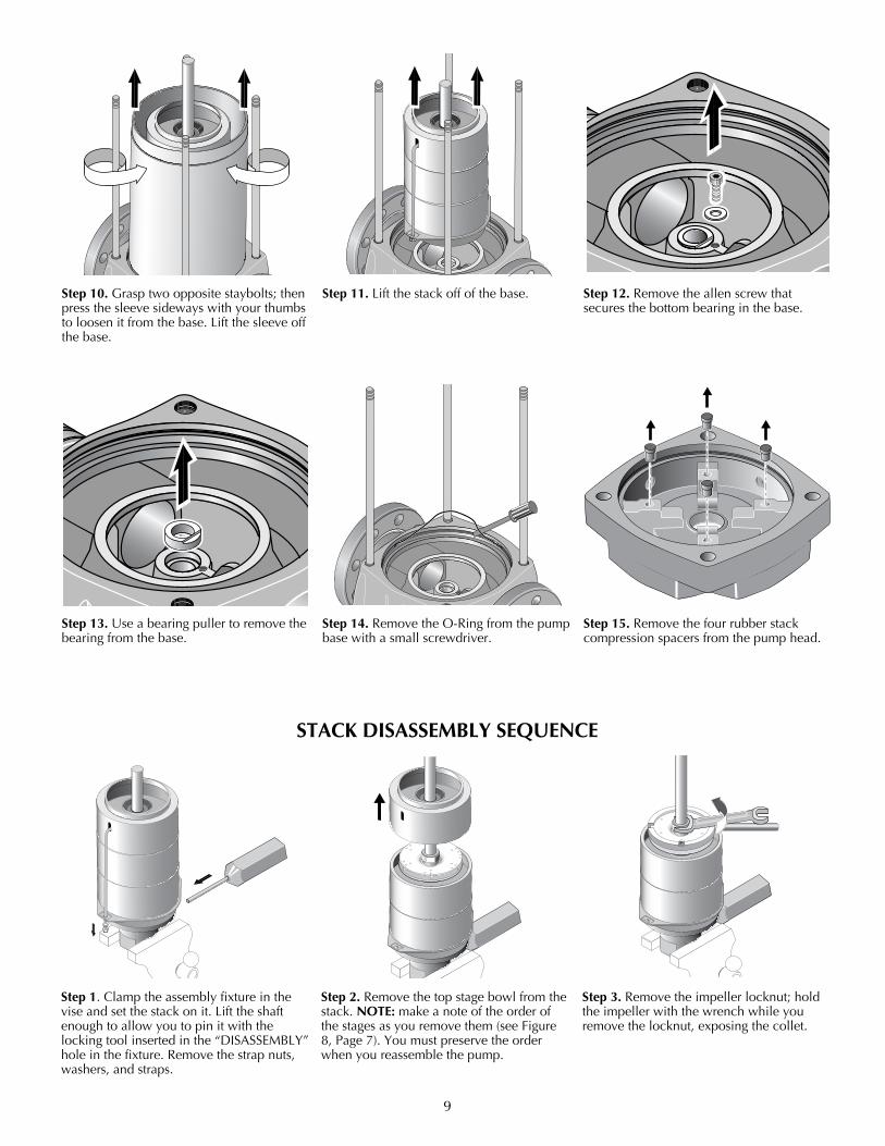
Step 10. Grasp two opposite staybolts; then press the sleeve sideways with your thumbs to loosen it from the base. Lift the sleeve off the base.
4968 0405Step 11. Lift the stack off of the base.4969 0405
Step 12. Remove the allen screw that secures the bottom bearing in the base.
4970 0405Step 13. Use a bearing puller to remove the bearing from the base.
4971 0405Step 14. Remove the O-Ring from the pump base with a small screwdriver.
4973 0405Step 1. Clamp the assembly fixture in the vise and set the stack on it. Lift the shaft enough to allow you to pin it with the locking tool inserted in the “DISASSEMBLY” hole in the fixture. Remove the strap nuts, washers, and straps.
4974 0405Step 2. Remove the top stage bowl from the stack. NOTE: make a note of the order of thestagesasyouremovethem(seeFigure8,Page7).Youmustpreservetheorderwhen you reassemble the pump.
4975 0405Step 3. Remove the impeller locknut; hold the impeller with the wrench while you remove the locknut, exposing the collet.
STACk DISASSEMBLY SEqUENCE
Step 15. Remove the four rubber stack compression spacers from the pump head.
4972 0405
10
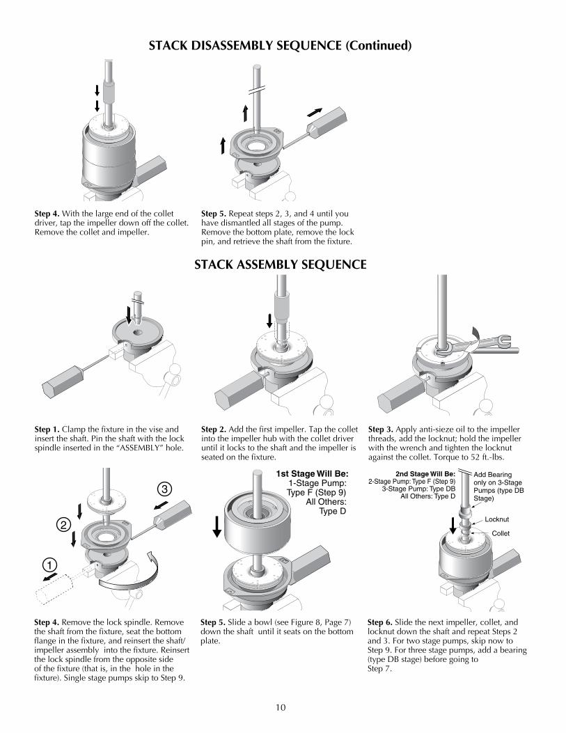
4976 0405Step 4. With the large end of the collet driver, tap the impeller down off the collet. Remove the collet and impeller.
4977 0405Step 5. Repeat steps 2, 3, and 4 until you have dismantled all stages of the pump. Remove the bottom plate, remove the lock pin, and retrieve the shaft from the fixture.
4979 0405Step 2. Add the first impeller. Tap the collet into the impeller hub with the collet driver until it locks to the shaft and the impeller is seated on the fixture.
4980 0405Step 3. Apply anti-sieze oil to the impeller threads, add the locknut; hold the impeller with the wrench and tighten the locknut against the collet. Torque to 52 ft.-lbs.
1
2
3
4981 0405Step 4. Remove the lock spindle. Remove the shaft from the fixture, seat the bottom flange in the fixture, and reinsert the shaft/impeller assembly into the fixture. Reinsert the lock spindle from the opposite side ofthefixture(thatis,inthe hole in the fixture).SinglestagepumpsskiptoStep9.
1st Stage Will Be:1-Stage Pump:
Type F (Step 9) All Others:
Type D
4982 0405Step 5.Slideabowl(seeFigure8,Page7)down the shaft until it seats on the bottom plate.
Add Bearing only on 3-StagePumps (type DBStage)
Locknut
Collet
2nd Stage Will Be:2-Stage Pump: Type F (Step 9)
3-Stage Pump: Type DBAll Others: Type D
4983 0405Step 6. Slide the next impeller, collet, and locknut down the shaft and repeat Steps 2 and3.Fortwostagepumps,skipnowtoStep9.Forthreestagepumps,addabearing(typeDBstage)beforegoingto Step 7.
STACk DISASSEMBLY SEqUENCE (Continued)
STACk ASSEMBLY SEqUENCE
Step 1. Clamp the fixture in the vise and insert the shaft. Pin the shaft with the lock spindle inserted in the “ASSEMBLY” hole.
4978 0405
11
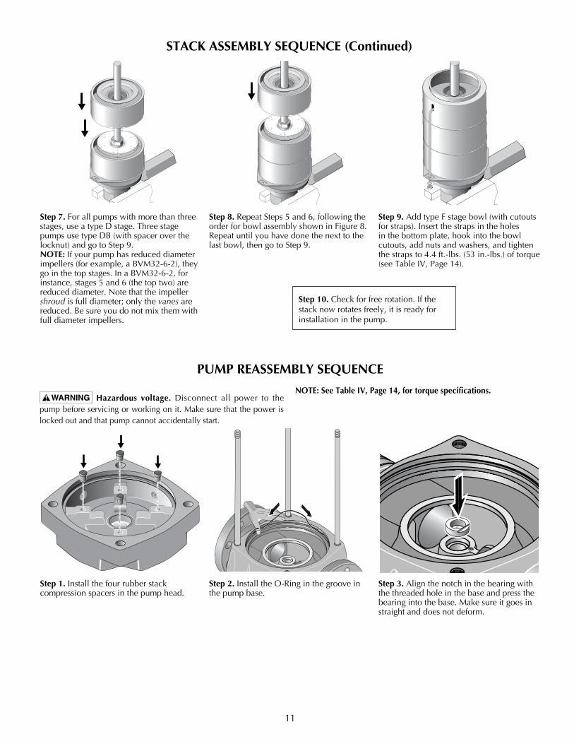
4984 0405Step 7.Forallpumpswithmorethanthreestages, use a type D stage. Three stage pumpsusetypeDB(withspaceroverthelocknut)andgotoStep9.NOTE: If your pump has reduced diameter impellers(forexample,aBVM32-6-2),theygo in the top stages. In a BVM32-6-2, for instance,stages5and6(thetoptwo)arereduced diameter. Note that the impeller shroud is full diameter; only the vanes are reduced. Be sure you do not mix them with full diameter impellers.
4985 0405Step 8. Repeat Steps 5 and 6, following the orderforbowlassemblyshowninFigure8.Repeat until you have done the next to the last bowl, then go to Step 9.
4986 0405Step 9.AddtypeFstagebowl(withcutoutsforstraps).Insertthestrapsintheholesin the bottom plate, hook into the bowl cutouts, add nuts and washers, and tighten thestrapsto4.4ft.-lbs.(53in.-lbs.)oftorque(seeTableIV,Page14).
STACk ASSEMBLY SEqUENCE (Continued)
PUMP REASSEMBLY SEqUENCE
4987 0405Step 1. Install the four rubber stack compression spacers in the pump head.
4988 0405Step 2. Install the O-Ring in the groove in the pump base.
4989 0405Step 3. Align the notch in the bearing with the threaded hole in the base and press the bearing into the base. Make sure it goes in straight and does not deform.
Hazardous voltage. Disconnect all power to the pump before servicing or working on it. Make sure that the power is locked out and that pump cannot accidentally start.
NOTE: See Table IV, Page 14, for torque specifications.
Step 10. Check for free rotation. If the stack now rotates freely, it is ready for installation in the pump.

12
PUMP REASSEMBLY SEqUENCE (Continued)
4990 0405Step 4A. Install the allen screw that secures the bottom bearing in the base. Tighten it to 6 ft- lbs. torque. Step 4B. If you removed the staybolts at disassembly, grease the threads and reinstall them now, tightening them to 75 ft.-lbs. torque.
4991 0405Step 5. Align the hole in the bottom plate with the pin on the base and install the stack on the base.
4992 0405Step 6. Install the sleeve in the base.
4993 0405Step 7. Lubricate the O-Ring and install it in the groove in the pump head.
4994 0405Step 8. Install the pump head on the pump and seat it with a rubber mallet. The vent plug must be over the discharge port in the pump base.
4995 0405Step 9. Lubricate the threads and Install the staybolt nuts and washers on the pump head. Cross-tighten them to 75 ft.-lbs. torque.
4996 0405Step 10A. Install the motor stool on the pump head. Grease the threads on the four allen screws that secure it, then install the allen screws and cross-tighten them to 45 ft.-lbs. torque.Step 10B. If you removed the motor at disassembly, reinstall it now. Grease the threads on the motor bolts and then install and cross-tighten them to 30 ft.-lbs. torque.
4997 0405Step 11. Lubricate the shaft seal and O-Rings. Install the seal on the shaft, making sure that it seats on the pump head.
4998 0405Step 12. Slide the seal carrier down the shaft until it seats solidly on the shaft seal flange. Grease the threads on the allen screws and install the screws. Cross-tighten them to 46 ft-lbs. torque.
13
PUMP REASSEMBLY SEqUENCE (Continued)
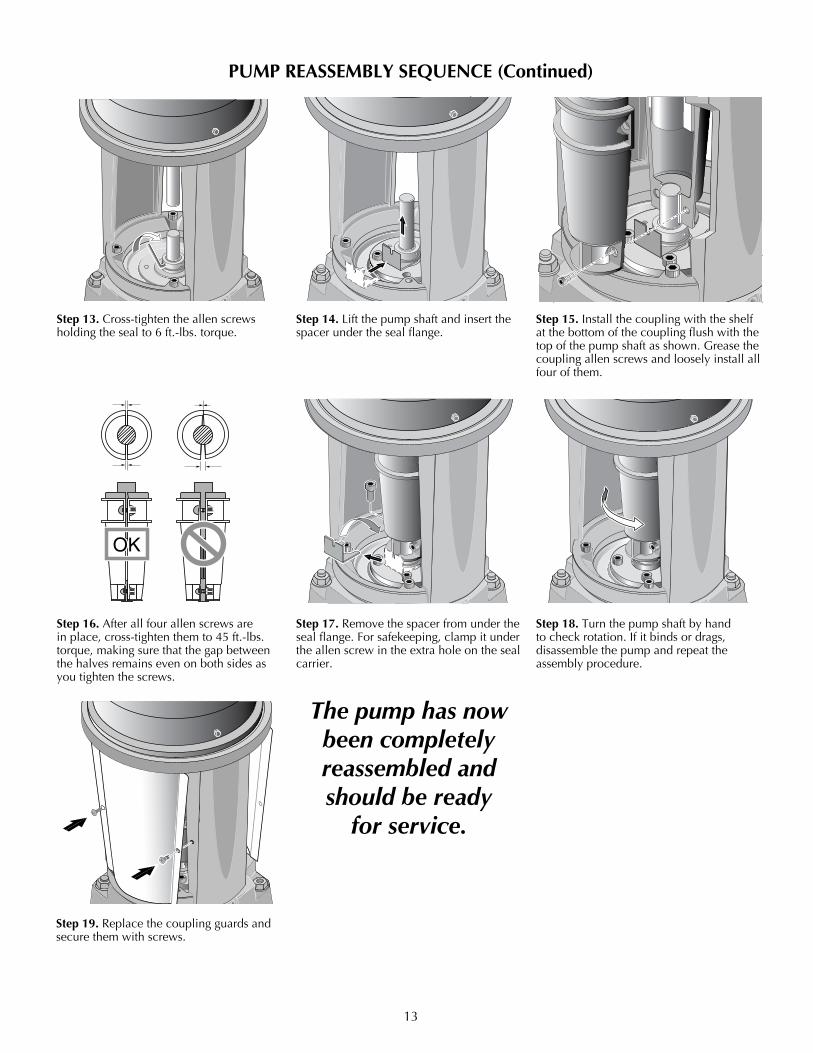
4999 0405Step 13. Cross-tighten the allen screws holding the seal to 6 ft.-lbs. torque.
5000 0405Step 14. Lift the pump shaft and insert the spacer under the seal flange.
5001 0405Step 15. Install the coupling with the shelf at the bottom of the coupling flush with the top of the pump shaft as shown. Grease the coupling allen screws and loosely install all four of them.
5002 0405Step 16. After all four allen screws are in place, cross-tighten them to 45 ft.-lbs. torque, making sure that the gap between the halves remains even on both sides as you tighten the screws.
5003 0405Step 17. Remove the spacer from under the sealflange.Forsafekeeping,clampitunderthe allen screw in the extra hole on the seal carrier.
5004 0405Step 18. Turn the pump shaft by hand to check rotation. If it binds or drags, disassemble the pump and repeat the assembly procedure.
5005 0405Step 19. Replace the coupling guards and secure them with screws.
The pump has now been completely reassembled and should be ready
for service.
14
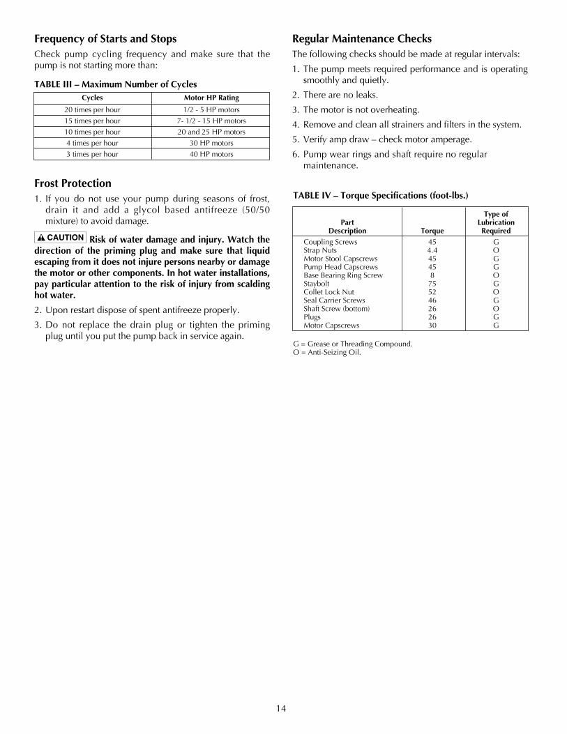
Frequency of Starts and StopsCheck pump cycling frequency and make sure that the pump is not starting more than:
Frost Protection1. If you do not use your pump during seasons of frost,
drain it and add a glycol based antifreeze (50/50mixture)toavoiddamage.
Risk of water damage and injury. Watch the direction of the priming plug and make sure that liquid escaping from it does not injure persons nearby or damage the motor or other components. In hot water installations, pay particular attention to the risk of injury from scalding hot water.
2. Upon restart dispose of spent antifreeze properly.
3. Do not replace the drain plug or tighten the priming plug until you put the pump back in service again.
Regular Maintenance ChecksThe following checks should be made at regular intervals:
1. The pump meets required performance and is operating smoothly and quietly.
2. There are no leaks.
3. The motor is not overheating.
4. Remove and clean all strainers and filters in the system.
5. Verify amp draw – check motor amperage.
6. Pump wear rings and shaft require no regular maintenance.
Cycles Motor HP Rating
20 times per hour 1/2 - 5 HP motors
15 times per hour 7- 1/2 - 15 HP motors
10 times per hour 20 and 25 HP motors
4 times per hour 30 HP motors
3 times per hour 40 HP motors
TABLE III – Maximum Number of Cycles
TABLE IV – Torque Specifications (foot-lbs.)
Type of Part Lubrication Description Torque Required
Coupling Screws 45 G Strap Nuts 4.4 O Motor Stool Capscrews 45 G Pump Head Capscrews 45 G Base Bearing Ring Screw 8 O Staybolt 75 G Collet Lock Nut 52 O Seal Carrier Screws 46 G ShaftScrew(bottom) 26 O Plugs 26 G Motor Capscrews 30 G
G = Grease or Threading Compound.O = Anti-Seizing Oil.

15
TROUBLESHOOTING GUIDE Hazardous voltage and risk of sudden starts. Disconnect all power to the pump before servicing or working
on pump. Make sure that power is locked out and that pump cannot be accidentally started.
PROBLEM CAUSE
1. Motor does not run when started A. Power failure B. Fusesblown C. Motor starter overload has tripped out D. Main contacts in motor starter are not making contact or the coil is faulty E Control circuit fuses are defective F. Motorisdefective 2. Motor starter overload trips out immediately A. One fuse has blown when power supply is switched on B. Contacts in motor overload relay are faulty C. Cable connections are loose or faulty D. Motor winding is defective E. Pump mechanically blocked F. Overloadsettingistoolow 3. Motor starter overload trips out occasionally A. Overload setting is too low B. Low voltage at peak times 4. Motorstarterhasnottrippedoutbutthemotor A. Check1A),B),D,)andE) does not run 5. Pump capacity is not constant A. Pump inlet pressure is too low B. Suction pipe/pump partly blocked C. Pump is sucking air 6. Pump runs but gives no water A. Suction pipe/pump blocked B. Footornon-returnvalveisblockedinclosedposition C. Leakage in suction pipe D. Air in suction pipe or pump E. Motor rotates in the wrong direction 7. Pump runs backwards when switched off A. Leakage in suction pipe B. Footornon-returnvalveisdefective C. Footvalveisblockedinopenorpartlyopenposition D. Non return valve leaks or is blocked in open or partly open position E. Discharge valve is defective 8. Leakage from shaft seal A. Pump shaft position is incorrect B. Shaft seal is defective 9. Noise A. Cavitation is occurring in the pump B. Pumpdoesnotrotatefreely(Thatis,thereisincreasedfrictionalresistance) because of incorrect shaft position
Limited WarrantyBERKELEY warrants to the original consumer purchaser (“Purchaser” or “You”) of the products listed below, that they will be free from defects in material and workmanship for the Warranty Period shown below.
Product Warranty Period
Water Systems:
Water Systems Products — jet pumps, small centrifugal pumps, submersible pumps and related accessorieswhichever occurs first: 12 months from date of original installation, or 18 months from date of manufacture
Pro-Source™ Composite Tanks 5 years from date of original installationPro-Source™ Steel Pressure Tanks 5 years from date of original installationPro-Source™ Epoxy-Lined Tanks 3 years from date of original installation
Sump/Sewage/Effluent Products12 months from date of original installation, or 18 months from date of manufacture
Agricultural/Commercial:Centrifugals – close-coupled motor drive, frame mount, SAE mount, engine drive, VMS, SSCX, SSHM, solids handling, submersible solids handling
12 months from date of original installation, or 24 months from date of manufacture
Submersible Turbines, 6” diameter and larger12 months from date of original installation, or 24 months from date of manufacture
Our limited warranty will not apply to any product that, in our sole judgement, has been subject to negligence, misapplication, improper installation, or improper maintenance. Without limiting the foregoing, operating a three phase motor with single phase power through a phase converter will void the warranty. Note also that three phase motors must be protected by three-leg, ambient compensated, extra-quick trip overload relays of the recommended size or the warranty is void.Your only remedy, and BERKELEY’s only duty, is that BERKELEY repair or replace defective products (at BERKELEY’s choice). You must pay all labor and shipping charges associated with this warranty and must request warranty service through the installing dealer as soon as a problem is discovered. No request for service will be accepted if received after the Warranty Period has expired. This warranty is not transferable.BERKELEY SHALL NOT BE LIABLE FOR ANY CONSEQUENTIAL, INCIDENTAL, OR CONTINGENT DAMAGES WHATSOEVER.THE FOREGOING LIMITED WARRANTIES ARE EXCLUSIVE AND IN LIEU OF ALL OTHER EXPRESS AND IMPLIED WARRANTIES, INCLUDING BUT NOT LIMITED TO IMPLIED WARRANTIES OF MERCHANTABILITY AND FITNESS FOR A PARTICULAR PURPOSE. THE FOREGOING LIMITED WARRANTIES SHALL NOT EXTEND BEYOND THE DURATION PROVIDED HEREIN.Some states do not allow the exclusion or limitation of incidental or consequential damages or limitations on the duration of an implied warranty, so the above limitations or exclusions may not apply to You. This warranty gives You specific legal rights and You may also have other rights which vary from state to state.This Limited Warranty is effective June 1, 2011 and replaces all undated warranties and warranties dated before June 1, 2011.
In the U.S.: BERKELEY, 293 Wright St., Delavan, WI 53115 In Canada: 269 Trillium Dr., Kitchener, Ontario N2G 4W5
16
2
3
67
10B10A
11
9
15
16
19
20212323
24A
2526
2526
2526
27A
29
24B
24C
27B
30
3132
27B
33
34
17
353637
41
43
42
40
1817
28
38
39
1
41A
5
8
121314
5006 0405
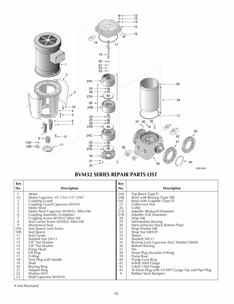
BVM32 SERIES REPAIR PARTS LIST
key key No. Description No. Description
1 Motor 24A TopBowl(TypeF) 1A MotorCapscrew1/2–13x1-1/2”UNC 24B BowlwithBearing(TypeDB) 2 CouplingGuard 24C BowlwithGraphite(TypeD) 3 Coupling Guard Capscrew M5X10 25 Collet Lock Nut 4 Motor Stool 26 Collet 5 MotorStoolCapscrewM10X55,AllenHd 27A Impeller(ReducedDiameter) 6 CouplingAssembly(Complete) 27B Impeller(FullDiameter) 7 Coupling Screw M10X25 Allen Hd 28 Strap M8 8 Seal Carrier Screw M10X25 Allen Hd 29 Intermediate Bearing 9 MechanicalSeal 30 Interconnector(StackBottomPlate) 10A Seal Spacer Lock Screw 31 Strap Washer M8 10B Seal Spacer 32 Strap Nut M8X20 11 Seal Carrier 33 Sleeve 12 Staybolt Nut 5/8-11 34 Staybolt 5/8-11 13 5/8”StarWasher 35 BearingLockCapscrew(Incl.Washer)M6X8 14 5/8”FlatWasher 36 BottomBearing 15 Pump Head 37 Pin 16 FillPlug 38 DrainPlug(IncludesO-Ring) 17 O-Ring 39 Pump Base 18 VentPlugwithNeedle 40 FlangeLockRing 19 Shaft 41 8-Bolt300#Flange 20 BearingRing 42 4-Bolt150#Flange 21 Adapter Ring 43 SS Drain Plug with 1/4 NPT Gauge Tap and Pipe Plug 22 WasherM10 • RubberStackBumpers 23 Shaft Capscrew M10X16
•NotIllustrated.