Embed Size (px)
Citation preview

UNITED STATES STOVE COMPANY227 Industrial Park Road
P.O.Box 151South Pittsburg, TN 37380
800-750-2723www.USSTOVE.com
Models 1357M & 1557MOWNER'S MANUAL
SOLID FUELWARM AIR FURNACE
FOR PARALLEL INSTALLATION WITH EXISTING FORCED AIR-GAS OR OIL FIRED FURNACE (U.S. ONLY)
FOR INSTALLATION AS A CENTRAL FURNACEALL MODELS CERTIFIED UNDER UL 391
85591U-1905E
CAUTION:READ ALL INSTRUCTIONS CARE-FULLY BEFORE STARTING THE INSTALLATION OR OPERATING
THE FURNACE
IMPROPER INSTALLATION MAY VOID YOUR WARRANTY
DO NOT USE THIS FURNACEIN A MOBILE HOME OR TRAILER
U.S. Environmental Protection Agency Certified to comply with 2015 particulate emissions standards.
2
NOTE: YOUR UNIT MUST BE INSTALLED BY A QUALIFIED FURNACE INSTALLER.
You've purchased one of America's Finest Wood and Coal Burning Furnaces. By heat-ing with wood and coal you're helping CONSERVE AMERICA'S ENERGY! Wood is our Renewable Energy Resource. Please do your part to preserve our wood supply. Plant at least one tree each year. Future generations will thank you.
CONGRATULATIONS!
TOOLS
Pencil6 Foot Folding Rule or TapeTin SnipsDrill, Hand or ElectricDrill Bit- 1/8" Dia. (For Sheet Metal Screws)Screw Driver (Blade-Type)GlovesSabre Saw5/16" Nut Driver or 5/16" Socket w/RatchetSafety Glasses
MATERIAL
6" Pipe, 6" Elbow, Collar and Thimble; as required (24 gauge min.)1/2" Sheet Metal Screws6" Inside diameter Listed Residential Type or Building Heating Appliance Chimney or existing masonry chimneyElectrical Wiring6" Draft Regulator1/2" Conduit (Conduit Connectors)Furnace Cement (Manufacturer Recommends: Rutland Black-Code 78 or Equivalent)Plenum and Duct work as required.
TOOLS AND MATERIALS NEEDED
3
Caution LabelsCaution LabelsYour Furnace has the following labels. Read and Obey all labels.
DANGER: RISK OF FIRE OR EXPLOSION.
DO NOT burn garbage, gasoline, drain oil, or other fl ammable liquids.
WARNING: FIRE HAZARD.
DO NOT operate with fi re draft exceeding .06 inches w.c.
DO NOT operate with fuel loading or ash removal doors open.
DO NOT store fuels, paints, thinners, fl ammable liquids, or other highly volatile sub-stances in the furnace room.
CAUTION:HOT SURFACES! Keep children away. Do not touch during operation.
SAFETY NOTICE:If this heater is not properly installed, a house fi re may result. For your safety, follow the installation directions. Contact local building or fi re of-fi cials about restrictions and installation inspection requirements in your area. If not already installed, we recommend that smoke detectors be
installed.
CAUTION!CLEANOUT OF THE HEAT EXCHANGER, FLUE PIPE, CHIMNEY, AND DRAFT INDUCER (IF USED), IS ESPECIALLY IMPORTANT AT THE END OF THE HEATING SEASON TO MINIMIZE CORROSION DURING THE
SUMMER MONTHS, CAUSED BY ACCUMULATED ASH.
CAUTION!INSPECT FLUE PIPES, FLUE PIPE JOINTS AND FLUE PIPE SEALS REGULARLY TO ENSURE THAT SMOKE AND FLUE GASES ARE NOT DRAWN INTO, AND CIRCULATED BY, THE AIR CIRCULATION SYSTEM.
4
Rules for safe installation and operationRead these rules and the instructions carefully. Failure to follow them will cause a hazard that could
result in death, serious bodily injury, and/or property damage.
Your Furnace is designed to be installed in a parallel air fl ow arrangement with a gas or oil-fi red forced air upfl ow-type central furnace, or it may be installed as a central furnace.
1. Check your local codes. The installation must comply with their rulings.
2. Do not install this furnace in a mobile home or trailer.3. Always connect this furnace to a chimney and vent to
the outside. Never vent to another room or inside a building.
4. Do not connect this furnace to an aluminum Type B gas vent. This is not safe and is prohibited by the National Fire Protection Association Code. This furnace requires a masonry or Listed Factory Built Chimney for residential type or Building Heating Appliance Chimney. Use a 6" diameter chimney or larger, that is high enough to give a good draft.
5. Be sure that if a masonry chimney is used, it is safely constructed and in good repair. Have the chimney inspected by the Fire Department or an inspector.
6. Inspect chimney connector and chimney before and frequently during the heating season for any deposit of creosote or soot which must be removed.
7. Provide air for combustion into the room where the fur-nace is located. If the intake is not in the same room, air must have free access to the room.
8. CAST IRON PARTS MUST BE "SEASONED" TO AVOID CRACKING, BUILD ONLY SMALL FIRES ON FIRST USE.
9. To prevent injury, do not allow anyone to use this fur-nace who is unfamiliar with the correct operation of the furnace.
10. For further information on using your furnace safely, obtain a copy of the National Fire Protection Association (NFPA) publication "Chimney's, Fireplaces and Solid Fuel Burning Appliances" NFPA 211. The address of the NFPA is Batterymarch Park, Quincy, MA 02269.
11. Keep the ashpit section free of excess ashes. Do not allow ashes to stack higher than the sides of the ash pan.
12. DISPOSAL OF ASHES- Place ashes in a metal container with a tight fi tting lid. Keep the closed container on a noncombustible fl oor or on the ground, well away from all combustible materials. Keep the ashes in the closed container until all cinders have thoroughly cooled. The ashes may be buried in the ground or picked up by a refuse collector.
13. CAUTION- The special paints used on your furnace may give off some smoke while they are curing dur-
ing fi rst few fi res., Build small fi res at fi rst. The metal used in construction of the furnace and duct work has a light coating of oil. This could give off smoke and/or odor from registers when furnace is used for the fi rst time. This should disappear after a short period of time. Once this burn-off has occurred, it should not reoccur.
14. CARING FOR PAINTED PARTS- This furnace has a painted outside jacket, which is durable, but it will not stand rough handling or abuse. When installing your furnace, use care in handling. Clean with soap and warm water when furnace in not hot. DO NOT use any acids or scouring soap, as these wear and dull the fi nish. DISCOLORATION WILL OCCUR IF THE FURNACE IS OVERHEATED. FOLLOW OPERATING INSTRUCTIONS CAREFULLY.
15. Keep the feed and ash doors closed at all times except while tending the furnace.
CAUTIONNEVER USE GASOLINE, GASOLINE-TYPE LAN-TERN FUEL, KEROSENE, CHARCOAL LIGHTER FLUID, OR FLAMMABLE LIQUIDS TO START OR
"FRESHEN UP" A FIRE IN THE FURNACE.
CAUTIONDO NOT OPERATE WITH THE FEED AND/OR ASH DOOR OPEN. THIS FURNACE IS DESIGNED FOR THERMOSTATIC OPERATION. OPERATION WITH ANY OF THESE DOORS OPEN WILL OVERHEAT
AND DAMAGE THE FURNACE.
CAUTIONGASES THAT ARE DRIVEN FROM FRESH COAL MUST BE BURNED OR THEY WILL ACCUMULATE AND EXPLODE. NEVER SMOTHER A FIRE WHEN
ADDING FRESH COAL.
WARNINGNEVER STORE FLAMMABLE LIQUIDS, ESPE-CIALLY GASOLINE, IN THE VICINITY OF THE
FURNACE.
5
Your HOTBLAST Furnace is designed to be a supplemental or central heating source for your home. This Solid Fuel Furnace may be installed in conjunction with a properly oper-ating central furnace that is listed or certifi ed in accordance with nationally recognized safety standards and equipped with the required controls and other safety features and which has been installed in accordance with appropriate standards of the National Fire Protection Association with installation clearances specifi ed in the furnace nameplate marking. The installation must be accomplished by a qualifi ed agency (one who is engaged in, and is responsible for, or is thoroughly familiar with the installation and operation of the gas, oil, and solid fuel burning heating appliances, who is experienced in such work, familiar with all the requirements of the authority having jurisdiction.) The installation shall be in strict accordance with the manufacturer's installation instructions furnished with the solid fuel furnace.The chimney connector of the furnace is to be installed to provide clearances to combustible material not less than specifi ed in the individual classifi cations and marked on the furnace. The chimney connector must be connected to a chimney suitable for use with residential type or building heating appliances which burn solid fuel.The Furnace is designed to operate in either parallel or series air fl ow arrangement with the central furnace or as a central furnace.
CENTRAL FURNACE INSTALLATIONAs a central furnace, the unit functions independently of any other system. The blower will come on when the plenum temperature reaches the setting on the blower control.
PARALLEL INSTALLATION: (U.S. ONLY)The design is such that when the blower comes on, the blower on the central system also comes on. The blower will only come on when the temperature in the plenum has reached the setting on the blower control. This is to insure that there is suffi cient warm air in the system to make it effi cient for the unit to operate. When the central system thermostat calls for heat, the central system will operate by the burner igniting and the blower coming on. It is possible that both systems will operate simultaneously. It is recommended that for the most effi cient use of your HOTBLAST Furnace, that it be fi red as much as possible in order to reduce the demand on your existing central heating system. This unit has an optional forced draft kit that operates from a wall thermostat. When the temperature falls below the setting on the wall thermostat, the forced draft will come on (U.S.
Stove Option 11/DIKL)The warm air supply outlet of the HOTBLAST Furnace shall not be connected to the cold air return of the central furnace, because the possibility exists of components of the central furnace overheating and causing the central furnace to operate other than is intended.
SERIES INSTALLATIONThis type of installation uses only the blowers of the existing central furnace. The solid fuel fan/limit control must also control the functions of the existing furnace. All electrical power must come from a single branch circuit.
HOW THE FURNACE FUNCTIONS

6
DIMENSIONS OF FURNACE
Figure 2Model 1557M
Figure 1Model 1357M
7
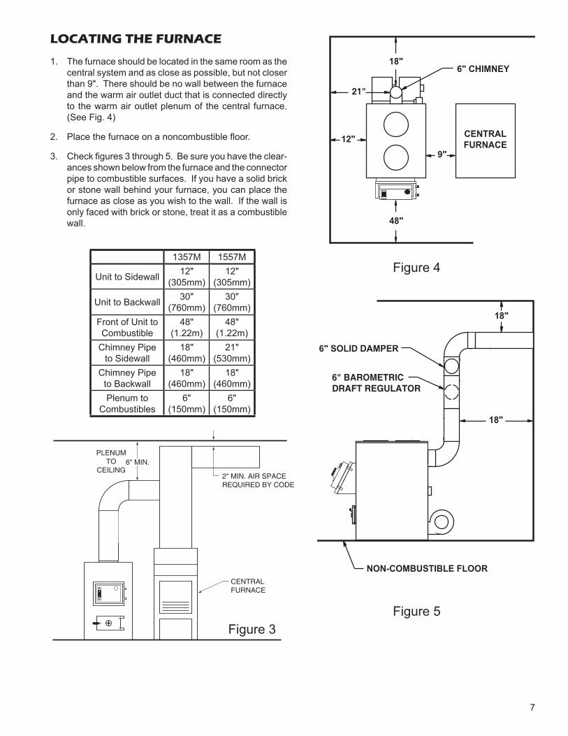
LOCATING THE FURNACE
1. The furnace should be located in the same room as the central system and as close as possible, but not closer than 9". There should be no wall between the furnace and the warm air outlet duct that is connected directly to the warm air outlet plenum of the central furnace. (See Fig. 4)
2. Place the furnace on a noncombustible fl oor.
3. Check fi gures 3 through 5. Be sure you have the clear-ances shown below from the furnace and the connector pipe to combustible surfaces. If you have a solid brick or stone wall behind your furnace, you can place the furnace as close as you wish to the wall. If the wall is only faced with brick or stone, treat it as a combustible wall.
18"
18"
6" SOLID DAMPER
6" BAROMETRICDRAFT REGULATOR
NON-COMBUSTIBLE FLOOR
12"9"
48"
18"
CENTRALFURNACE
6" CHIMNEY
21"
Figure 4
Figure 5
1357M 1557M
Unit to Sidewall 12"(305mm)
12"(305mm)
Unit to Backwall 30"(760mm)
30"(760mm)
Front of Unit to Combustible
48"(1.22m)
48"(1.22m)
Chimney Pipe to Sidewall
18"(460mm)
21"(530mm)
Chimney Pipe to Backwall
18"(460mm)
18"(460mm)
Plenum to Combustibles
6"(150mm)
6"(150mm)
2" MIN. AIR SPACEREQUIRED BY CODE
CENTRALFURNACE
6" MIN.PLENUM
TOCEILING
Figure 3
8
10'
2' MIN.
3' MIN.
6" CHIMNEY CONNECTOR
6" ELBOW
6" SOLID DAMPER
6" BAROMETRICDRAFT REGULATOR
REFER TO CHIMNEYMANUFACTURER'SINSTRUCTIONS ANDPARTS.
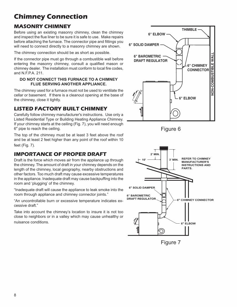
Chimney ConnectionMASONRY CHIMNEYBefore using an existing masonry chimney, clean the chimney and inspect the fl ue liner to be sure it is safe to use. Make repairs before attaching the furnace. The connector pipe and fi ttings you will need to connect directly to a masonry chimney are shown.The chimney connection should be as short as possible.If the connector pipe must go through a combustible wall before entering the masonry chimney, consult a qualifi ed mason or chimney dealer. The installation must conform to local fi re codes, and N.F.P.A. 211.
DO NOT CONNECT THIS FURNACE TO A CHIMNEY FLUE SERVING ANOTHER APPLIANCE.
The chimney used for a furnace must not be used to ventilate the cellar or basement. If there is a cleanout opening at the base of the chimney, close it tightly.
LISTED FACTORY BUILT CHIMNEY Carefully follow chimney manufacturer's instructions. Use only a Listed Residential Type or Building Heating Appliance Chimney. If your chimney starts at the ceiling (Fig. 7), you will need enough 6" pipe to reach the ceiling.The top of the chimney must be at least 3 feet above the roof and be at least 2 feet higher than any point of the roof within 10 feet (Fig. 7).
IMPORTANCE OF PROPER DRAFTDraft is the force which moves air from the appliance up through the chimney. The amount of draft in your chimney depends on the length of the chimney, local geography, nearby obstructions and other factors. Too much draft may cause excessive temperatures in the appliance. Inadequate draft may cause backpuffi ng into the room and ‘plugging’ of the chimney.“Inadequate draft will cause the appliance to leak smoke into the room through appliance and chimney connector joints.”“An uncontrollable burn or excessive temperature indicates ex-cessive draft.”Take into account the chimney’s location to insure it is not too close to neighbors or in a valley which may cause unhealthy or nuisance conditions.
6" SOLID DAMPER
6" BAROMETRICDRAFT REGULATOR
THIMBLE6" ELBOW
6" CHIMNEYCONNECTOR
6" ELBOW
NO
N-C
OM
BU
ST
IBL
E W
AL
L
Figure 6
Figure 7
9
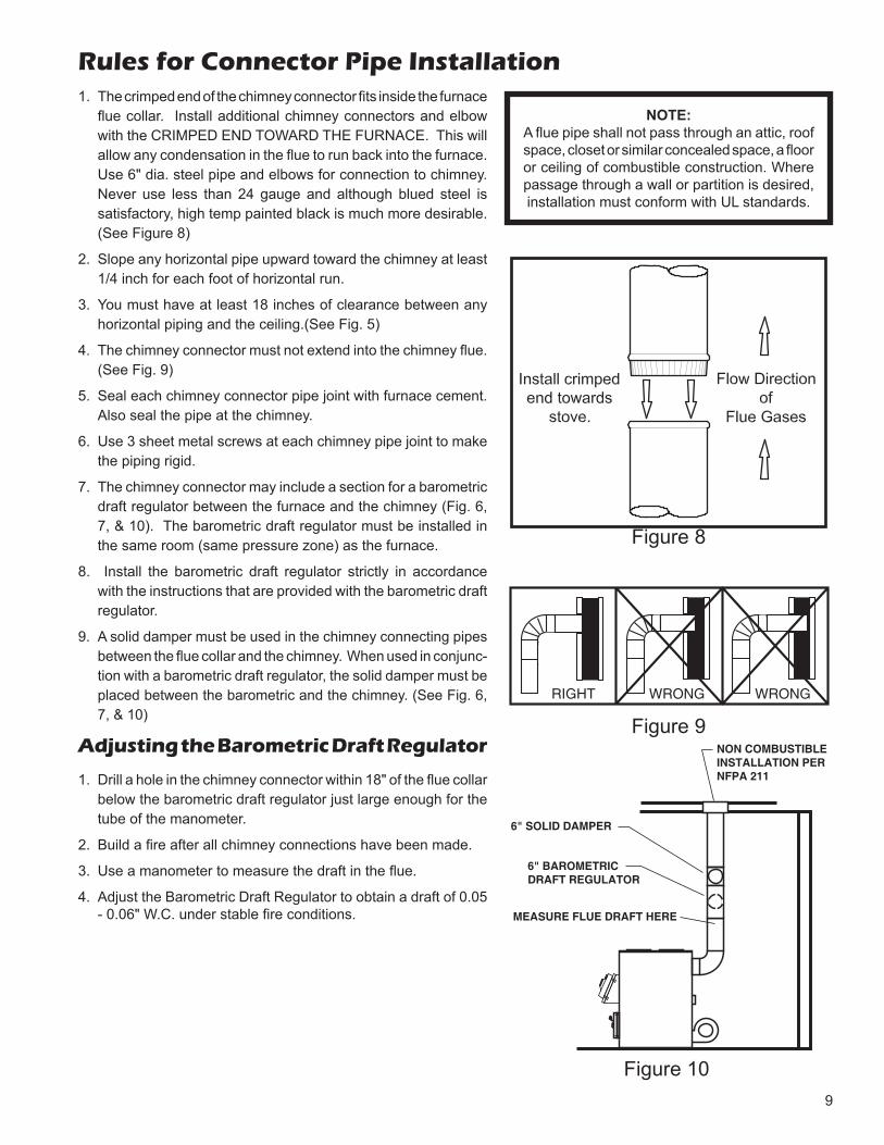
1. The crimped end of the chimney connector fi ts inside the furnace fl ue collar. Install additional chimney connectors and elbow with the CRIMPED END TOWARD THE FURNACE. This will allow any condensation in the fl ue to run back into the furnace. Use 6" dia. steel pipe and elbows for connection to chimney. Never use less than 24 gauge and although blued steel is satisfactory, high temp painted black is much more desirable. (See Figure 8)
2. Slope any horizontal pipe upward toward the chimney at least 1/4 inch for each foot of horizontal run.
3. You must have at least 18 inches of clearance between any horizontal piping and the ceiling.(See Fig. 5)
4. The chimney connector must not extend into the chimney fl ue. (See Fig. 9)
5. Seal each chimney connector pipe joint with furnace cement. Also seal the pipe at the chimney.
6. Use 3 sheet metal screws at each chimney pipe joint to make the piping rigid.
7. The chimney connector may include a section for a barometric draft regulator between the furnace and the chimney (Fig. 6, 7, & 10). The barometric draft regulator must be installed in the same room (same pressure zone) as the furnace.
8. Install the barometric draft regulator strictly in accordance with the instructions that are provided with the barometric draft regulator.
9. A solid damper must be used in the chimney connecting pipes between the fl ue collar and the chimney. When used in conjunc-tion with a barometric draft regulator, the solid damper must be placed between the barometric and the chimney. (See Fig. 6, 7, & 10)
Adjusting the Barometric Draft Regulator
1. Drill a hole in the chimney connector within 18" of the fl ue collar below the barometric draft regulator just large enough for the tube of the manometer.
2. Build a fi re after all chimney connections have been made.
3. Use a manometer to measure the draft in the fl ue.
4. Adjust the Barometric Draft Regulator to obtain a draft of 0.05 - 0.06" W.C. under stable fi re conditions.
RIGHT WRONG WRONG
6" SOLID DAMPER
6" BAROMETRICDRAFT REGULATOR
NON COMBUSTIBLEINSTALLATION PERNFPA 211
MEASURE FLUE DRAFT HERE
Figure 9
Figure 10
Rules for Connector Pipe Installation
NOTE:A fl ue pipe shall not pass through an attic, roof space, closet or similar concealed space, a fl oor or ceiling of combustible construction. Where passage through a wall or partition is desired, installation must conform with UL standards.
Figure 8
10
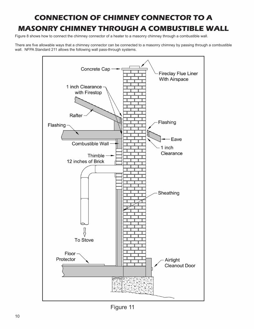
CONNECTION OF CHIMNEY CONNECTOR TO A
MASONRY CHIMNEY THROUGH A COMBUSTIBLE WALLFigure 8 shows how to connect the chimney connector of a heater to a masonry chimney through a combustible wall.
There are fi ve allowable ways that a chimney connector can be connected to a masonry chimney by passing through a combustible wall. NFPA Standard 211 allows the following wall pass-through systems.
Figure 11
11
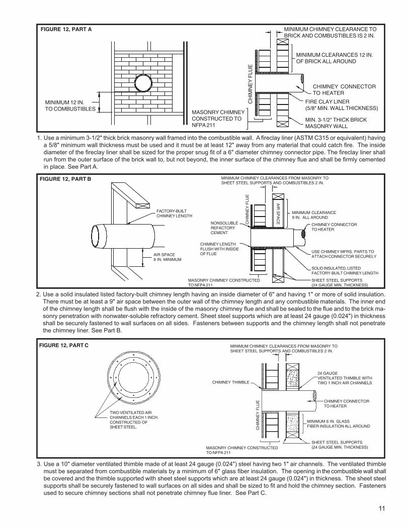
1. Use a minimum 3-1/2" thick brick masonry wall framed into the combustible wall. A fi reclay liner (ASTM C315 or equivalent) having a 5/8" minimum wall thickness must be used and it must be at least 12" away from any material that could catch fi re. The inside diameter of the fi reclay liner shall be sized for the proper snug fi t of a 6" diameter chimney connector pipe. The fi reclay liner shall run from the outer surface of the brick wall to, but not beyond, the inner surface of the chimney fl ue and shall be fi rmly cemented in place. See Part A.
MINIMUM 12 IN.TO COMBUSTIBLES
FIGURE 12, PART A
CH
IMN
EY
FLU
E
MINIMUM CHIMNEY CLEARANCE TOBRICK AND COMBUSTIBLES IS 2 IN.
MINIMUM CLEARANCES 12 IN.OF BRICK ALL AROUND
CHIMNEY CONNECTORTO HEATER
FIRE CLAY LINER(5/8" MIN. WALL THICKNESS)
MIN. 3-1/2" THICK BRICKMASONRY WALL
MASONRY CHIMNEYCONSTRUCTED TONFPA 211
FIGURE 12, PART B
AIR SPACE9 IN. MINIMUM
FACTORY-BUILTCHIMNEY LENGTH
MINIMUM CHIMNEY CLEARANCES FROM MASONRY TOSHEET STEEL SUPPORTS AND COMBUSTIBLES 2 IN.
CHIMNEY LENGTHFLUSH WITH INSIDEOF FLUE
NONSOLUBLEREFACTORYCEMENT
MASONRY CHIMNEY CONSTRUCTEDTO NFPA 211
CHIMNEY CONNECTORTO HEATER
MINIMUM CLEARANCE9 IN. ALL AROUND
SHEET STEEL SUPPORTS(24 GAUGE MIN. THICKNESS)
CH
IMN
EY
FLU
E
SOLID INSULATED, LISTEDFACTORY-BUILT CHIMNEY LENGTH
USE CHIMNEY MFRS. PARTS TOATTACH CONNECTOR SECURELY
AIR
SP
AC
E
2. Use a solid insulated listed factory-built chimney length having an inside diameter of 6" and having 1" or more of solid insulation. There must be at least a 9" air space between the outer wall of the chimney length and any combustible materials. The inner end of the chimney length shall be fl ush with the inside of the masonry chimney fl ue and shall be sealed to the fl ue and to the brick ma-sonry penetration with nonwater-soluble refractory cement. Sheet steel supports which are at least 24 gauge (0.024") in thickness shall be securely fastened to wall surfaces on all sides. Fasteners between supports and the chimney length shall not penetrate the chimney liner. See Part B.
TWO VENTILATED AIRCHANNELS EACH 1 INCH.CONSTRUCTED OFSHEET STEEL.
FIGURE 12, PART C
MASONRY CHIMNEY CONSTRUCTEDTO NFPA 211
SHEET STEEL SUPPORTS(24 GAUGE MIN. THICKNESS)
MINIMUM CHIMNEY CLEARANCES FROM MASONRY TOSHEET STEEL SUPPORTS AND COMBUSTIBLES 2 IN.
MINIMUM 6 IN. GLASSFIBER INSULATION ALL AROUND
24 GAUGEVENTILATED THIMBLE WITHTWO 1 INCH AIR CHANNELSCHIMNEY THIMBLE
CH
IMN
EY
FLU
E CHIMNEY CONNECTORTO HEATER
3. Use a 10" diameter ventilated thimble made of at least 24 gauge (0.024") steel having two 1" air channels. The ventilated thimble must be separated from combustible materials by a minimum of 6" glass fi ber insulation. The opening in the combustible wall shall be covered and the thimble supported with sheet steel supports which are at least 24 gauge (0.024") in thickness. The sheet steel supports shall be securely fastened to wall surfaces on all sides and shall be sized to fi t and hold the chimney section. Fasteners used to secure chimney sections shall not penetrate chimney fl ue liner. See Part C.
12
SHEET STEEL SUPPORTS
CHIMNEY SECTION
CHIMNEYCONNECTOR
AIR SPACE2 IN.
FIGURE 12, PART D
MINIMUM CLEARANCE2 IN. ALL AROUND
CHIMNEY THIMBLE 1 IN. AIR SPACE TOCHIMNEY LENGTH
MASONRY CHIMNEY CONSTRUCTEDTO NFPA 211
SHEET STEEL SUPPORTS(24 GAUGE MIN. THICKNESS)
CH
IMN
EY
FLU
E
MINIMUM CHIMNEY CLEARANCES FROM MASONRY TOSHEET STEEL SUPPORTS AND COMBUSTIBLES 2 IN.
CHIMNEY CONNECTORTO HEATER
SOLID INSULATED, LISTEDFACTORY-BUILT CHIMNEY LENGTH (12 IN. LONG MIN.)
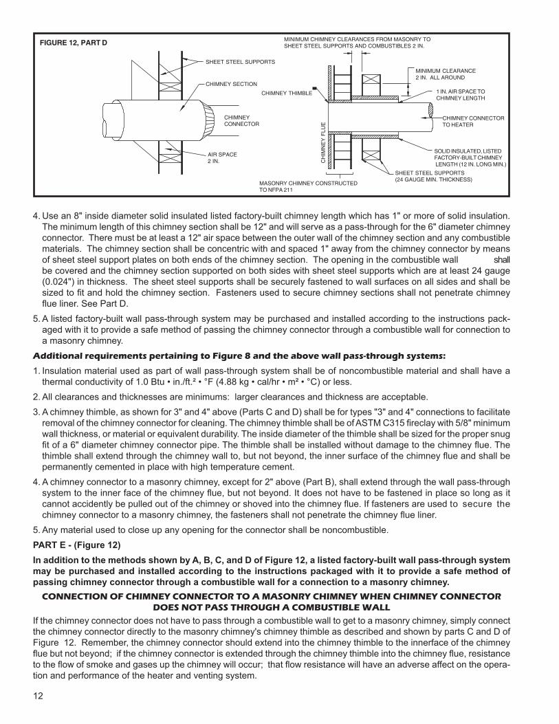
4. Use an 8" inside diameter solid insulated listed factory-built chimney length which has 1" or more of solid insulation. The minimum length of this chimney section shall be 12" and will serve as a pass-through for the 6" diameter chimney connector. There must be at least a 12" air space between the outer wall of the chimney section and any combustible materials. The chimney section shall be concentric with and spaced 1" away from the chimney connector by means of sheet steel support plates on both ends of the chimney section. The opening in the combustible wall shall be covered and the chimney section supported on both sides with sheet steel supports which are at least 24 gauge (0.024") in thickness. The sheet steel supports shall be securely fastened to wall surfaces on all sides and shall be sized to fi t and hold the chimney section. Fasteners used to secure chimney sections shall not penetrate chimney fl ue liner. See Part D.
5. A listed factory-built wall pass-through system may be purchased and installed according to the instructions pack-aged with it to provide a safe method of passing the chimney connector through a combustible wall for connection to a masonry chimney.
Additional requirements pertaining to Figure 8 and the above wall pass-through systems:
1. Insulation material used as part of wall pass-through system shall be of noncombustible material and shall have a thermal conductivity of 1.0 Btu • in./ft.² • °F (4.88 kg • cal/hr • m² • °C) or less.
2. All clearances and thicknesses are minimums: larger clearances and thickness are acceptable.3. A chimney thimble, as shown for 3" and 4" above (Parts C and D) shall be for types "3" and 4" connections to facilitate
removal of the chimney connector for cleaning. The chimney thimble shall be of ASTM C315 fi reclay with 5/8" minimum wall thickness, or material or equivalent durability. The inside diameter of the thimble shall be sized for the proper snug fi t of a 6" diameter chimney connector pipe. The thimble shall be installed without damage to the chimney fl ue. The thimble shall extend through the chimney wall to, but not beyond, the inner surface of the chimney fl ue and shall be permanently cemented in place with high temperature cement.
4. A chimney connector to a masonry chimney, except for 2" above (Part B), shall extend through the wall pass-through system to the inner face of the chimney fl ue, but not beyond. It does not have to be fastened in place so long as it cannot accidently be pulled out of the chimney or shoved into the chimney flue. If fasteners are used to secure the chimney connector to a masonry chimney, the fasteners shall not penetrate the chimney fl ue liner.
5. Any material used to close up any opening for the connector shall be noncombustible.PART E - (Figure 12)In addition to the methods shown by A, B, C, and D of Figure 12, a listed factory-built wall pass-through system may be purchased and installed according to the instructions packaged with it to provide a safe method of passing chimney connector through a combustible wall for a connection to a masonry chimney.
CONNECTION OF CHIMNEY CONNECTOR TO A MASONRY CHIMNEY WHEN CHIMNEY CONNECTORDOES NOT PASS THROUGH A COMBUSTIBLE WALL
If the chimney connector does not have to pass through a combustible wall to get to a masonry chimney, simply connect the chimney connector directly to the masonry chimney's chimney thimble as described and shown by parts C and D of Figure 12. Remember, the chimney connector should extend into the chimney thimble to the innerface of the chimney fl ue but not beyond; if the chimney connector is extended through the chimney thimble into the chimney fl ue, resistance to the fl ow of smoke and gases up the chimney will occur; that fl ow resistance will have an adverse affect on the opera-tion and performance of the heater and venting system.
13
THERMODISC
THERMODISCCOVER
4” ELECTRICAL JUNCTION BOX
BLOWERS
BLOWERS GASKETCLIP NUTS(Not used in the upper center hole.)
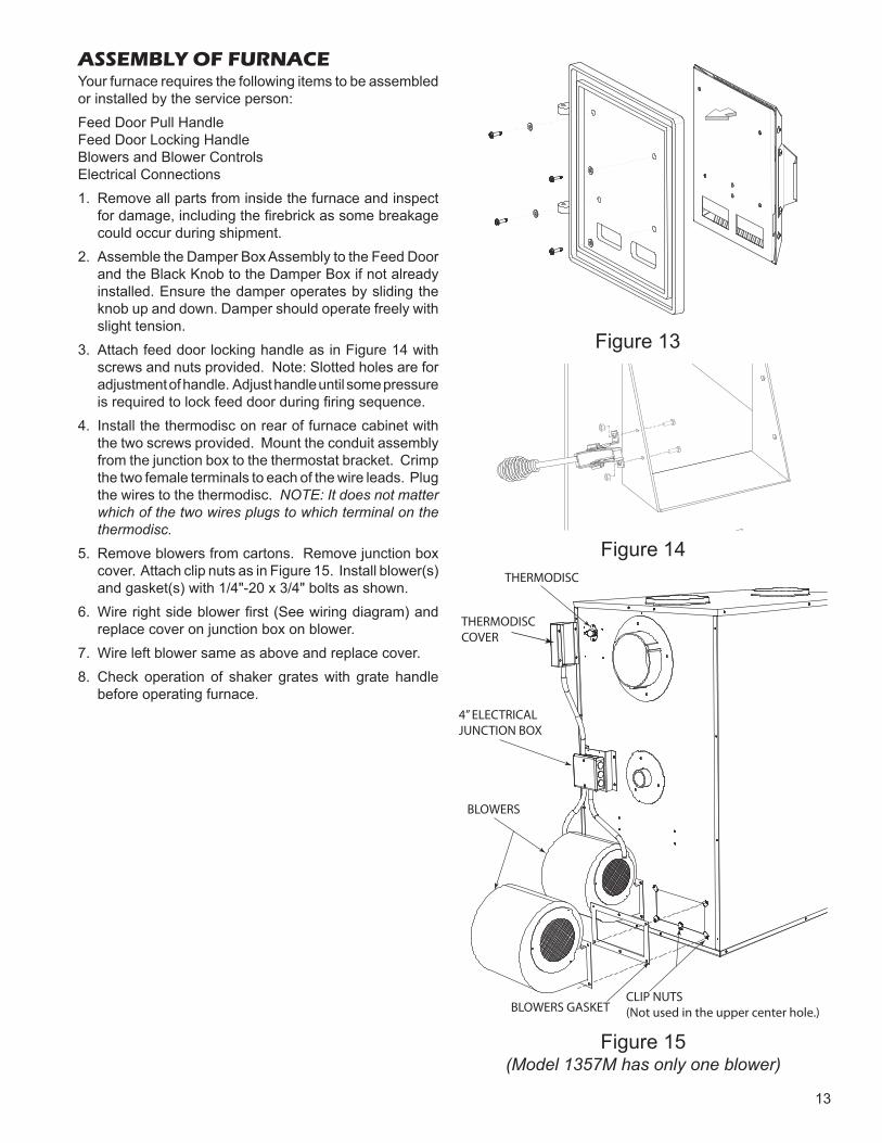
ASSEMBLY OF FURNACEYour furnace requires the following items to be assembled or installed by the service person:Feed Door Pull HandleFeed Door Locking HandleBlowers and Blower ControlsElectrical Connections1. Remove all parts from inside the furnace and inspect
for damage, including the fi rebrick as some breakage could occur during shipment.
2. Assemble the Damper Box Assembly to the Feed Door and the Black Knob to the Damper Box if not already installed. Ensure the damper operates by sliding the knob up and down. Damper should operate freely with slight tension.
3. Attach feed door locking handle as in Figure 14 with screws and nuts provided. Note: Slotted holes are for adjustment of handle. Adjust handle until some pressure is required to lock feed door during fi ring sequence.
4. Install the thermodisc on rear of furnace cabinet with the two screws provided. Mount the conduit assembly from the junction box to the thermostat bracket. Crimp the two female terminals to each of the wire leads. Plug the wires to the thermodisc. NOTE: It does not matter which of the two wires plugs to which terminal on the thermodisc.
5. Remove blowers from cartons. Remove junction box cover. Attach clip nuts as in Figure 15. Install blower(s) and gasket(s) with 1/4"-20 x 3/4" bolts as shown.
6. Wire right side blower fi rst (See wiring diagram) and replace cover on junction box on blower.
7. Wire left blower same as above and replace cover.8. Check operation of shaker grates with grate handle
before operating furnace.
Figure 15(Model 1357M has only one blower)
Figure 14
Figure 13
14
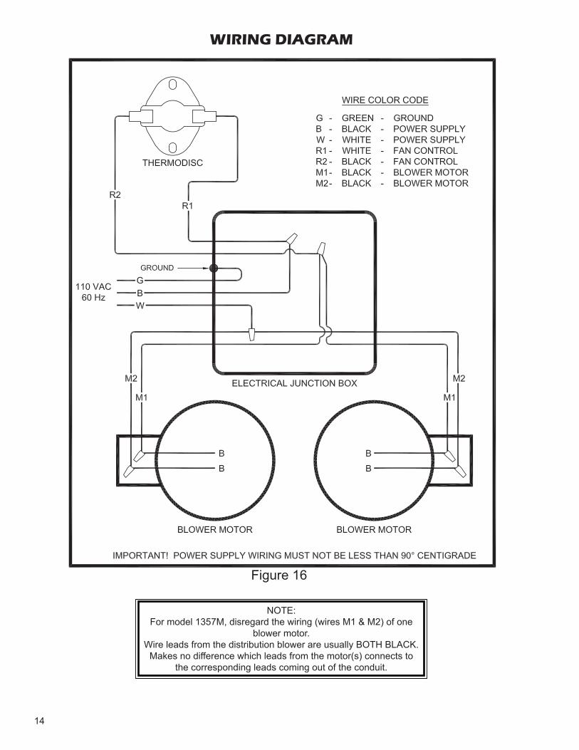
NOTE:For model 1357M, disregard the wiring (wires M1 & M2) of one
blower motor.Wire leads from the distribution blower are usually BOTH BLACK.
Makes no difference which leads from the motor(s) connects to the corresponding leads coming out of the conduit.
Figure 16
WIRING DIAGRAM
15
INSTALLATIONPlease see all methods of Installation at the rear of this booklet.This is a furnace, not a free standing stove. You must direct heated air from 8" outlets away from the furnace, or it will not function properly.1. This installation must be done by a qualifi ed heating
equipment installer.2. The installation is to be done in compliance with National
Fire Protection Association installation standards: No. 89M, 90B, 211, 70 (National Electrical Code) and Uniform Mechanical Code 913, 6-4, in the states where applicable. (Their code offers connecting smoke pipe connectors into chimney with other fuel burning appliances.)
3. Rooms large in comparison with size of the appliance:a) Wood or Coal Burning Furnace needs air for combus-
tion and circulation to house.b) Provision must be made to make up this air and not
starve gas or oil furnace of combustion air.c) Have the "Authority Having Jurisdiction" determine
that air is of adequate makeup. (Reference N.F.P.A. Nos. 30&54, Code for Installation of Gas & Oil Equip-ment).
4. Have the"Authority Having Jurisdiction" to inspect all chimneys and installations for adequate venting and for compliance with standard and local codes and regula-tions regarding installation of wood burning appliances.
5. Installation for Supplemental Heat Application to Existing Central System.a) Place Wood or Coal Burning Furnace so that the
chimney connector will be as short as practical and avoiding unnecessary sharp turns in the smoke pipe connector and the installation of devices that would create excessive resistance to the fl ow of fl ue gases.
b) Locate the Wood or Coal Burning Furnace as close as practical to the existing central hot air heating system, maintaining clearances as stated on the label on the fuel door.
c) Clearance from combustible materials must comply with those stated on the label on the side of the unit. Refer to the clearance table in the front of this manual.
The installation must be made only on a noncombustible fl oor.d) Install the smoke pipe connector to the chimney
with 26-gauge pipe and elbows (to be purchased separately), maintaining the proper clearances for the specifi c model. Seal the smoke pipe in the chimney with furnace cement. (The chimney connector shall be securely supported, and joints fastened with sheet metal screws or rivets.)
e) Install 8" diameter heat pipe to plenum of the central hot air furnace. Use 26-gauge pipe and connectors (to be purchased separately). If central air conditioning is installed in the plenum, install heat pipe above the air conditioning unit. Secure heat pipe connection with supports and sheet metal screws.
f) Connect electrical supply in the electrical junction box that is mounted on the back of the Furnace. See Wiring Diagram (Fig. 16). Remove the cover from electrical junction box and connect power supply wires to wires designated, using wire nuts. The power cord supplied may be used for installation, if permitted by local codes and regulations. If the power cord sup-plied cannot be used, the power supply wiring must be 90 degrees centigrade in a metal cable and should be completed by a qualifi ed installer complying with NFPA Standard No. 70 and local codes.
POWER FAILURE INSTRUCTIONSOperation after loss of power:1. Remove fi lter if provided2. Do not expect to keep home at normal temperatures.3. Do not load fuel above bottom of feed door.
16
OPERATING INSTRUCTIONSThe top down method of fi re building is recommended for this appliance. After making sure that the stove air intake controls are fully open (completely pull-out towards you), Place the largest pieces of wood on the bottom, laid in parallel and close together. Smaller pieces are placed in a second layer, crossways to the fi rst. A third layer of still smaller pieces is laid crossways to the second, this time with some spaces between. Then a fourth layer of loose, small kindling and twisted newspaper sheets tops off the pile.Higher effi ciencies and lower emissions generally result when burning air dried seasoned hardwoods, as compared to softwoods or to green or freshly cut hardwoods. DO NOT BURN:1. Garbage;2. Lawn clippings or yard waste;3. Materials containing rubber, including tires;4. Materials containing plastic;5. Waste petroleum products, paints or paint thinners, or
asphalt products;6. Materials containing asbestos;7. Construction or demolition debris;8. Railroad ties or pressure-treated wood;9. Manure or animal remains;10. Salt water driftwood or other previously salt water
saturated materials;11. Unseasoned wood; or12. Paper products, cardboard, plywood, or particleboard.
The prohibition against burning these materials does not prohibit the use of fi re starters made from paper, cardboard, saw dust, wax and similar substances for the purpose of starting a fi re in an affected wood heater.
Burning these materials may result in release of toxic fumes or render the heater ineffective and cause smoke.Dead wood lying on the forest fl oor should be considered wet, and requires full seasoning time. Standing dead wood can usually be considered to be about 2/3 seasoned. Split-ting and stacking wood before it is stored accelerates drying time. Storing wood on an elevated surface from the ground and under a cover or covered area from rain or snow also accelerates drying time. A good indicator if wood is ready to burn is to check the piece ends. If there are cracks radiating in all directions from the center then the wood should be dry enough to burn. If your wood sizzles in the fi re, even though the surface is dry, it may not be fully cured, and should be seasoned longer.
TAMPER WARNINGThis wood heater has a manufacturer-set minimum low burn rate that must not be altered. It is against federal regulations to alter this setting or otherwise operate this wood heater in a manner inconsistent with operating instructions in this manual.
VISIBLE SMOKEThe amount of visible smoke being produced can be an ef-fective method of determining how effi ciently the combustion process is taking place at the given settings. Visible smoke consist of unburned fuel and moisture leaving your stove. Learn to adjust the air settings of your specifi c unit to pro-duce the smallest amount of visible smoke. Wood that has not been seasoned properly and has a high wood moisture content will produce excess visible smoke and burn poorly. Use the included moisture meter to insure your wood has a 20% or less moisture content.
EFFICIENCIES Effi ciencies can be based on either the lower heating value (LHV) or the higher heating value (HHV) of the fuel. The lower heating value is when water leaves the combustion process as a vapor, in the case of woodstoves the moisture in the wood being burned leaves the stove as a vapor. The higher heating value is when water leaves the combustion process completely condensed. In the case of woodstoves this would assume the exhaust gases are room temperature when leaving the system, and therefore calculations using this heating value consider the heat going up the chimney as lost energy. Therefore, effi ciency calculated using the lower heating value of wood will be higher than effi ciency calculated using the higher heating value. In the United States all woodstove effi ciencies should be calculated using the higher heating value. The best way to achieve optimum effi ciencies is to learn the burn characteristic of you appliance and burn well-seasoned wood. Higher burn rates are not always the best heating burn rates; after a good fi re is established a lower burn rate may be a better option for effi cient heating. A lower burn rate slows the fl ow of usable heat out of the home through the chimney, and it also consumes less wood.
FUELModels 1357M & 1557MEgg size (1-3/16" or larger) bituminous coal for residential furnaces, or any of the specially packed fi replace coals can be used. Coal with a low ash content (2% to 6%) is recommended.
Hardwood, 18" to 26" should be split and air dried (sea-soned) for 6 months.
LIGHTING1. Set the thermostat on "HIGH" for maximum draft.
2. Open the feed door and place paper and kindling on the grate for starting the fi re.
3. Light the fi re and close the feed door.
4. Add wood or about 15 lbs. of coal (depending on which model) after fi re is burning briskly.
5. "MEDIUM" setting is normally satisfactory. Set higher or lower for your comfort.
17
A draft reading of .05 to .06 w.c. is suggested for proper burning of this unit when using wood or bituminous coal as fuel. When using anthracite coal, this draft reading is a minimum reading.
CAUTIONA chimney fi re may cause ignition of wall studs or rafters which you thought were a safe distance from the chimney. If you have a chimney fi re, have your chimney inspected by a qualifi ed person before using again.
ADDING FUELWhen starting a fi re, add small amounts of fuel instead of adding large quantities of fuel. This will give more complete combustion and less build-up of tars or soot in the chimney.
1. Set thermostat to HIGH before opening feed door.
2. Wood fi re: Add wood to a convenient level.
3. Coal Fire:
a.) Never smother the fi re when adding coal. Gases from the accumulation smoke will explode under certain conditoins. Add fresh kindling if the bed of coals has cooled.
b.) Add up to 20 lbs. of coal per loading. Never add coal above the bottom of feed door opening.
c.) Stir the coal and watch the fi re. Be sure the new coal is burning briskly before you close the doors and turn the thermostat down.
d.) Shake grates vigorously 1/2" left to right to spill ashes into the ash pan. Do this at least once every 12 hours of operation. Empty ash pan regularly. Do not allow ashes to build-up to grate as grate will warp and burnout, and you might spill the ashes when removing the pan. Dispose of hot ashes properly.
e.) Rotation of the handle (5 o'clock to 7 o'clock) posi-tion will agitate coals and spill ashes into ash pan.
f.) It is advisable for you to get familiar with the shaker grate operation before fi ring.
OVER FIRINGAttempts to achieve heat output rates that exceed heater design specifi cations can result in permanent damage to
the heater.
ASH REMOVAL AND DISPOSAL Whenever ashes get 3 to 4 inches deep in your fi rebox or ash pan, and when the fi re has burned down and cooled, remove excess ashes. Leave an ash bed approximately 1 inch deep on the fi rebox bottom to help maintain a hot charcoal bed.Ashes should be placed in a metal container with a tight-fi tting lid. The closed container of ashes should be placed on a noncombustible fl oor or on the ground, away from all
combustible materials, pending fi nal disposal. The ashes should be retained in the closed container until all cinders have thoroughly cooled.
SMOKE AND CO MONITORSBurning wood naturally produces smoke and carbon monoxide(CO) emissions. CO is a poisonous gas when exposed to elevated concentrations for extended periods of time. While the modern combustion systems in heaters drastically reduce the amount of CO emitted out the chim-ney, exposure to the gases in closed or confi ned areas can be dangerous. Make sure your stove gaskets and chimney joints are in good working order and sealing properly to en-sure unintended exposure. It is recommended that you use both smoke and CO monitors in areas having the potential to generate CO.
GASKETSIt is recommended that you change the door gasket (which makes your stove door air tight) once a year, in order to in-sure good control over the combustion, maximum effi ciency and security. To change the door gasket, simply remove the damaged one. Carefully clean the available gasket groove, apply a high temperature silicone sold for this purpose, and install the new gasket. You may light up your stove again approximately 24 hours after having completed this opera-tion. This unit’s ash door uses a 5/8" diameter rope gasket, and the feed door uses a 1/2" diameter rope gasket.
OPERATIONAL TIPSOperational Tips for Good, Effi cient, and Clean Com-
bustion
• Get the appliance hot and establish a good coal bed before adjusting to a low burn rate (this may take 30 minutes or more depending on your wood)
• Use smaller pieces of wood during start-up and a high burn rate to increase the stove temperature
• Be considerate of the environment and only burn dry wood
• Burn small, intense fi res instead of large, slow burn-ing fi res when possible
• Learn your appliance's operating characteristics to obtain optimum performance
18
• Burning unseasoned wet wood only hurts your stoves effi ciency and leads to accelerated creosote buildup in your chimney
SERVICE HINTSDo not expect a furnace to draw. It is the chimney that creates the draft. Smoke spillage into the house or excessive build-up of water or creosote in the chimney are warnings that the chimney is not functioning prop-erly. Correct the problem before using furnace. Possible causes are:1. The connector pipe may be pushed into the chimney too
far, stopping the draft.2. Do not connect two furnaces or a stove and furnace into
the same chimney fl ue.3. The chimney used for a furnace must not be used to
ventilate the cellar or basement. If there is a cleanout opening at the base of the chimney, it must be closed tightly.
4. If the chimney is operating too cool, water will condense in the chimney and run back into the furnace. Creosote formation will be rapid and may block the chimney. Operate the furnace at a high enough fi re to keep the chimney warm, preventing this condensation.
5. If the fi re burns well, but sometimes smokes or burns slowly, it may be caused by the chimney top being lower than another part of the house or a nearby tree. The wind blowing over a house or a tree, falls on top of the chimney like water over a dam, beating down the smoke. The top of the chimney should be at least 3 feet above the roof and be at least 2 feet higher than any point of
the roof within 10 feet.
6. See page 18 for list of trouble shooting tips.
CHIMNEY MAINTENANCECreosote and Soot - Formation and Need for RemovalWhen wood is burned slowly, it produces tar and other or-ganic vapors, which combine with expelled moisture to form creosote. The creosote vapors condense in the relatively cool chimney fl ue of a slow-burning fi re. As a result, creo-sote residue accumulates on the fl ue lining. When ignited, this creosote makes an extremely hot fi re.When coal is burned, the products of combustion combine with moisture to form a soot residue which accumulates on the fl ue lining. When ignited, this soot makes an extremely hot fi re.The chimney should be inspected at least twice monthly during the heating season to determine if a creosote or soot build up has occurred.If creosote or soot has accumulated, it should be removed to reduce the risk of a chimney fi re.Chimney fi res burn very hot. If the chimney catches fi re, immediately call the fi re department, then reduce the fi re by closing the inlet air control. Pour a large quantity of coarse salt, baking soda or cool ashes on top of the fi re in the fi rebox.
ATTENTION:This wood heater needs periodic inspection and repair for proper operation. It is against federal regulations to operate this wood heater in a manner inconsistent with operating instructions in this manual.
19
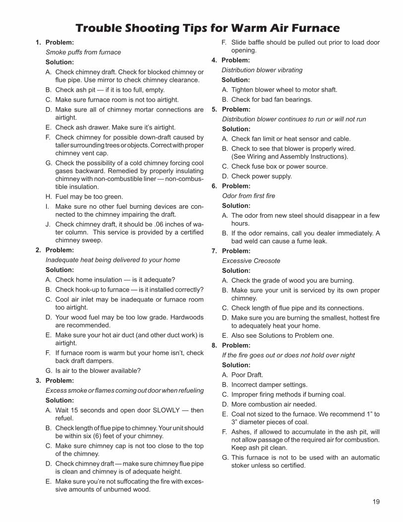
Trouble Shooting Tips for Warm Air Furnace1. Problem: Smoke puffs from furnace Solution:
A. Check chimney draft. Check for blocked chimney or fl ue pipe. Use mirror to check chimney clearance.
B. Check ash pit — if it is too full, empty.C. Make sure furnace room is not too airtight.D. Make sure all of chimney mortar connections are
airtight.E. Check ash drawer. Make sure it’s airtight.F. Check chimney for possible down-draft caused by
taller surrounding trees or objects. Correct with proper chimney vent cap.
G. Check the possibility of a cold chimney forcing cool gases backward. Remedied by properly insulating chimney with non-combustible liner — non-combus-tible insulation.
H. Fuel may be too green.I. Make sure no other fuel burning devices are con-
nected to the chimney impairing the draft.J. Check chimney draft, it should be .06 inches of wa-
ter column. This service is provided by a certifi ed chimney sweep.
2. Problem: Inadequate heat being delivered to your home Solution:
A. Check home insulation — is it adequate?B. Check hook-up to furnace — is it installed correctly?C. Cool air inlet may be inadequate or furnace room
too airtight.D. Your wood fuel may be too low grade. Hardwoods
are recommended.E. Make sure your hot air duct (and other duct work) is
airtight.F. If furnace room is warm but your home isn’t, check
back draft dampers.G. Is air to the blower available?
3. Problem: Excess smoke or fl ames coming out door when refueling Solution:
A. Wait 15 seconds and open door SLOWLY — then refuel.
B. Check length of fl ue pipe to chimney. Your unit should be within six (6) feet of your chimney.
C. Make sure chimney cap is not too close to the top of the chimney.
D. Check chimney draft — make sure chimney fl ue pipe is clean and chimney is of adequate height.
E. Make sure you’re not suffocating the fi re with exces-sive amounts of unburned wood.
F. Slide baffl e should be pulled out prior to load door opening.
4. Problem: Distribution blower vibrating Solution:
A. Tighten blower wheel to motor shaft. B. Check for bad fan bearings.
5. Problem: Distribution blower continues to run or will not run Solution:
A. Check fan limit or heat sensor and cable. B. Check to see that blower is properly wired. (See Wiring and Assembly Instructions). C. Check fuse box or power source. D. Check power supply.
6. Problem: Odor from fi rst fi re Solution:
A. The odor from new steel should disappear in a few hours.
B. If the odor remains, call you dealer immediately. A bad weld can cause a fume leak.
7. Problem: Excessive Creosote Solution:
A. Check the grade of wood you are burning. B. Make sure your unit is serviced by its own proper
chimney. C. Check length of fl ue pipe and its connections. D. Make sure you are burning the smallest, hottest fi re
to adequately heat your home. E. Also see Solutions to Problem one.
8. Problem: If the fi re goes out or does not hold over night Solution:
A. Poor Draft. B. Incorrect damper settings. C. Improper fi ring methods if burning coal. D. More combustion air needed. E. Coal not sized to the furnace. We recommend 1” to
3” diameter pieces of coal. F. Ashes, if allowed to accumulate in the ash pit, will
not allow passage of the required air for combustion. Keep ash pit clean.
G. This furnace is not to be used with an automatic stoker unless so certifi ed.
20
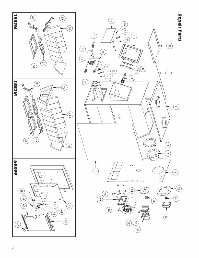
Re
pa
ir Pa
rts
22
6
8
7
9
2018
19
17
16
14 10
15
11
1213
21
1
5
23
41
28
27
26
29 3031
24
25
32
33
23
35
34
38
3736
40
38
36
37
3934
42 41
46
48
474443
4549
13
57
M1
55
7M
69
39
9

21
125541G
Cabinet Side (Left & Right)1357M
225467G 1557M
2 88032 Flue Collar Gasket 2
3 40246 Flue Collar 1
N/S 83227 Bolt, 1/4-20 x 1" 6
N/S 83250 Kep Nut, 1/4-20 6
425540G
Cabinet Back1357M
123459G 1557M
525561G
Cabinet Top1357M
125466G 1557M
N/S 891214 8" Collar 2
6 68217 Feed Door Assy. (Includes Gasket - 88057) 1
7 22662 Bracket, Feed Door 1
8 24232 Spacer, Hinge 1
9 891097 Locking Mechanism, Feed Door 1
10 68218 Ash Door Assy. (Includes Gasket - 88066) 1
11 86626 Latch, Door 1
12 83461 Washer (1" OD, 7/16" ID) 1
13 83274 Lock Nut, 3/8-16 1
14 891098 Handle Assy. w/Handle Bushing 1
15 23859B Draft Cap, Painted 1
16 89574 Handle, Spring 2
17 23800 Smoke Curtain 1
18 23787 Clip, Smoke Curtain 2
19 83445 1/4-20 x 1-1/4 Carriage Bolt 2
20 83250 Kep Nut, 1/4-20 2
2168238
Ash Pan1357M
168228 1557M
2223397
Baffl e, Flue1357M 1
23398 1557M 2
23 22761B Flue Collar Ring 1
24 22762B Forced Draft Ring 1
25 86402 1-1/2" Pipe Plug 1
26 80230 Blower1357M 11557M 2
27 89319 Gasket, Blower1357M 11557M 2
28 83340 1/4-20 Clipnut1357M 41557M 8
N/S 83339 Bolt (1/4-20 x 3/4")1357M 41557M 8
29 22140 Relay Box Bracket 1
30 80131 Junction Box (4 x 4) 1
31 80231 Junction Box Cover 1
32 80314 Thermodisc (60T12) 1
33 68234 Blower Thermostat Bracket 1
34 89066 Firebrick (4.5 x 9 x 1.25)1357M 101557M 12
35 40264 Liner, Front/Rear 1357M 2
36 40256 Grate Frame, Shaker1357M 1
1557M 2
37 40257 Grate, Shaker1357M 11557M 2
38 40260 Handle, Shaker 1
39 40258 Liner - Rear 1557M 1
40 40269 Liner - Front 1557M 1
41 69396 Control Plate Assembly 1
42 25200 Slide Damper 1
43 89041 Spring 1
44 83278 #10 Flat Washer 3
45 83244 10-24 Kep Nut 3
46 89943 Knob, Slide Damper 1
47 25197G Control Box Cover 1
48 25199G Pull Handle 1
49 83895 10-24 x 1-3/4 CS Machine Screw 1
N/S = Not Shown Color Code: G = Green
Key Part No. Description Model Qty.
Parts ListKey Part No. Description Model Qty.
IN ORDER TO MAINTAIN WARRANTY, COMPONENTS MUST BE REPLACED USING ORIGINAL MANUFACTURERS PARTS PURCHASED THROUGH YOUR DEALER OR DIRECTLY FROM THE
APPLIANCE MANUFACTURER. USE OF THIRD PARTY COMPONENTS WILL VOID THE WARRANTY.
22
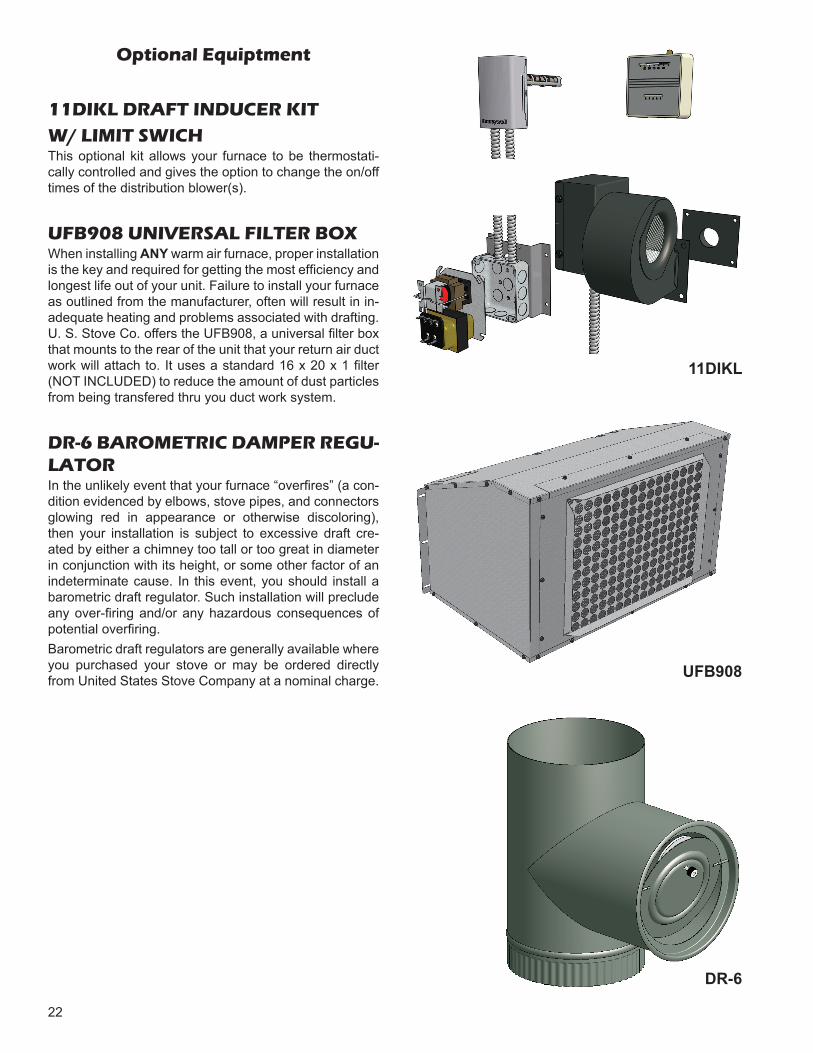
Optional Equiptment
11DIKL DRAFT INDUCER KIT W/ LIMIT SWICHThis optional kit allows your furnace to be thermostati-cally controlled and gives the option to change the on/off times of the distribution blower(s).
UFB908 UNIVERSAL FILTER BOXWhen installing ANY warm air furnace, proper installation is the key and required for getting the most effi ciency and longest life out of your unit. Failure to install your furnace as outlined from the manufacturer, often will result in in-adequate heating and problems associated with drafting. U. S. Stove Co. offers the UFB908, a universal fi lter box that mounts to the rear of the unit that your return air duct work will attach to. It uses a standard 16 x 20 x 1 fi lter (NOT INCLUDED) to reduce the amount of dust particles from being transfered thru you duct work system.
DR-6 BAROMETRIC DAMPER REGU-LATORIn the unlikely event that your furnace “overfi res” (a con-dition evidenced by elbows, stove pipes, and connectors glowing red in appearance or otherwise discoloring), then your installation is subject to excessive draft cre-ated by either a chimney too tall or too great in diameter in conjunction with its height, or some other factor of an indeterminate cause. In this event, you should install a barometric draft regulator. Such installation will preclude any over-fi ring and/or any hazardous consequences of potential overfi ring.Barometric draft regulators are generally available where you purchased your stove or may be ordered directly from United States Stove Company at a nominal charge. UFB908
DR-6
11DIKL
23
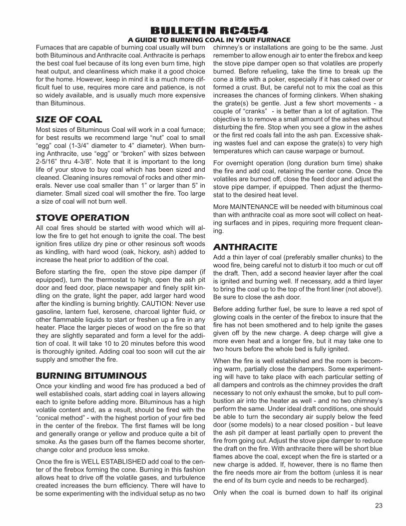
BULLETIN RC454A GUIDE TO BURNING COAL IN YOUR FURNACE
Furnaces that are capable of burning coal usually will burn both Bituminous and Anthracite coal. Anthracite is perhaps the best coal fuel because of its long even burn time, high heat output, and cleanliness which make it a good choice for the home. However, keep in mind it is a much more dif-fi cult fuel to use, requires more care and patience, is not so widely available, and is usually much more expensive than Bituminous.
SIZE OF COALMost sizes of Bituminous Coal will work in a coal furnace; for best results we recommend large “nut” coal to small “egg” coal (1-3/4” diameter to 4” diameter). When burn-ing Anthracite, use “egg” or “broken” with sizes between 2-5/16” thru 4-3/8”. Note that it is important to the long life of your stove to buy coal which has been sized and cleaned. Cleaning insures removal of rocks and other min-erals. Never use coal smaller than 1” or larger than 5” in diameter. Small sized coal will smother the fi re. Too large a size of coal will not burn well.
STOVE OPERATIONAll coal fi res should be started with wood which will al-low the fi re to get hot enough to ignite the coal. The best ignition fi res utilize dry pine or other resinous soft woods as kindling, with hard wood (oak, hickory, ash) added to increase the heat prior to addition of the coal.
Before starting the fi re, open the stove pipe damper (if epuipped), turn the thermostat to high, open the ash pit door and feed door, place newspaper and fi nely split kin-dling on the grate, light the paper, add larger hard wood after the kindling is burning brightly. CAUTION: Never use gasoline, lantern fuel, kerosene, charcoal lighter fl uid, or other fl ammable liquids to start or freshen up a fi re in any heater. Place the larger pieces of wood on the fi re so that they are slightly separated and form a level for the addi-tion of coal. It will take 10 to 20 minutes before this wood is thoroughly ignited. Adding coal too soon will cut the air supply and smother the fi re.
BURNING BITUMINOUSOnce your kindling and wood fi re has produced a bed of well established coals, start adding coal in layers allowing each to ignite before adding more. Bituminous has a high volatile content and, as a result, should be fi red with the “conical method” - with the highest portion of your fi re bed in the center of the fi rebox. The fi rst fl ames will be long and generally orange or yellow and produce quite a bit of smoke. As the gases burn off the fl ames become shorter, change color and produce less smoke.
Once the fi re is WELL ESTABLISHED add coal to the cen-ter of the fi rebox forming the cone. Burning in this fashion allows heat to drive off the volatile gases, and turbulence created increases the burn effi ciency. There will have to be some experimenting with the individual setup as no two
chimney’s or installations are going to be the same. Just remember to allow enough air to enter the fi rebox and keep the stove pipe damper open so that volatiles are properly burned. Before refueling, take the time to break up the cone a little with a poker, especially if it has caked over or formed a crust. But, be careful not to mix the coal as this increases the chances of forming clinkers. When shaking the grate(s) be gentle. Just a few short movements - a couple of “cranks” - is better than a lot of agitation. The objective is to remove a small amount of the ashes without disturbing the fi re. Stop when you see a glow in the ashes or the fi rst red coals fall into the ash pan. Excessive shak-ing wastes fuel and can expose the grate(s) to very high temperatures which can cause warpage or burnout.
For overnight operation (long duration burn time) shake the fi re and add coal, retaining the center cone. Once the volatiles are burned off, close the feed door and adjust the stove pipe damper, if epuipped. Then adjust the thermo-stat to the desired heat level.
More MAINTENANCE will be needed with bituminous coal than with anthracite coal as more soot will collect on heat-ing surfaces and in pipes, requiring more frequent clean-ing.
ANTHRACITEAdd a thin layer of coal (preferably smaller chunks) to the wood fi re, being careful not to disturb it too much or cut off the draft. Then, add a second heavier layer after the coal is ignited and burning well. If necessary, add a third layer to bring the coal up to the top of the front liner (not above!). Be sure to close the ash door.
Before adding further fuel, be sure to leave a red spot of glowing coals in the center of the fi rebox to insure that the fi re has not been smothered and to help ignite the gases given off by the new charge. A deep charge will give a more even heat and a longer fi re, but it may take one to two hours before the whole bed is fully ignited.
When the fi re is well established and the room is becom-ing warm, partially close the dampers. Some experiment-ing will have to take place with each particular setting of all dampers and controls as the chimney provides the draft necessary to not only exhaust the smoke, but to pull com-bustion air into the heater as well - and no two chimney’s perform the same. Under ideal draft conditions, one should be able to turn the secondary air supply below the feed door (some models) to a near closed position - but leave the ash pit damper at least partially open to prevent the fi re from going out. Adjust the stove pipe damper to reduce the draft on the fi re. With anthracite there will be short blue fl ames above the coal, except when the fi re is started or a new charge is added. If, however, there is no fl ame then the fi re needs more air from the bottom (unless it is near the end of its burn cycle and needs to be recharged).
Only when the coal is burned down to half its original
24
BULLETIN RC454A GUIDE TO BURNING COAL IN YOUR FURNACE
depth it is time to add fresh coal. When doing so, open the stove pipe damper and turn the thermostat damper to high, which will allow the fi re to burn off any accumulated gases. Open the feed door, and with a small rake, hoe, or hooked poker pull the glowing coals to the front of the fi rebox. Try not to disturb the fi re too much. Next, add a fresh charge to the back being careful not to seal off the top. Close the feed door, but leave the spin damper (or thermostat) open for a few minutes until the volatile gases have burned off. It is not necessary to shake down the ashes each time you refuel the furnace. Experience will be your best teacher.
BANKING THE FIREFor extended operation, such as overnight, the fi re will need to be banked. To do so heap coal up along the sides and back of the fi rebox so that the fi re gradually burns it over a longer period of time. The intensity of the fi re will also be reduced without letting it go out. Follow the same procedure as for refueling. If possible, avoid shaking, as a heavier layer of ash will help reduce the intensity of the fi re
during this time. After loading, let the fi re establish itself for about 30 minutes. Then close your damper and automatic control to the point where the house does not become too cold. It is important that you begin banking early enough before retiring or leaving that you can make necessary ad-justments after the fi re is well established.
To revive a coal fi re that is almost out, (1) open the ash door and stove pipe damper and close the spin damper under the door to get a good draft through the grate. (2) place a thin layer of dry coal over the entire top of the fi re. DO NOT POKE OR SHAKE THE FIRE AT THIS TIME! (3) after the fresh coal has become well ignited shake the grate (just a little), refuel.
DO NOT burn coke, charcoal, high volatile bituminous coal, sub bituminous, lignite or cannel coal (sometimes called channel coal or candle coal).
NEVER burn wax or chemically impregnated sawdust logs - their intended use is for fi replaces only.
NEVER fi ll the stove or furnace above the fi rebrick or cast iron liner.
25
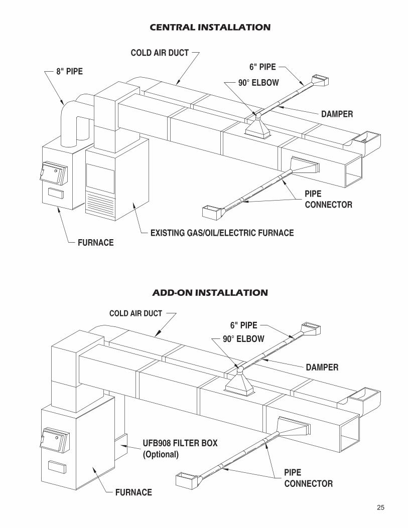
CENTRAL INSTALLATION
ADD-ON INSTALLATION
26
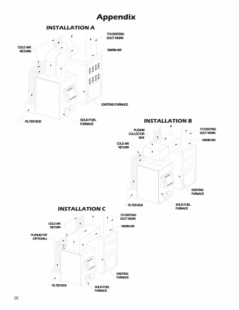
TO EXISTINGDUCT WORK
WARM AIR
EXISTING FURNACE
SOLID FUEL FURNACE
FILTER BOX
COLD AIRRETURN
TO EXISTINGDUCT WORK
WARM AIR
EXISTINGFURNACE
SOLID FUELFURNACE
FILTER BOX
PLENUMCOLLECTOR
BOX
COLD AIRRETURN
TO EXISTINGDUCT WORK
WARM AIR
EXISTINGFURNACE
SOLID FUELFURNACE
FILTER BOX
COLD AIRRETURN
PLENUM TOP(OPTIONAL)
AppendixINSTALLATION A
INSTALLATION B
INSTALLATION C
27
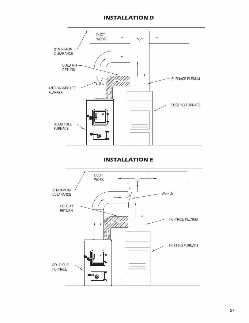
INSTALLATION D
INSTALLATION E

28
INSTALLATION H
TOP VIEW
FRONT VIEW
INSTALLATION F INSTALLATION G

29
NOTES

30
NOTES

31
NOTES
THIS MANUAL WILL HELP YOU OBTAIN EFFICIENT, DEPENDABLE SERVICE FROM YOUR FURNACE, AND ENABLE YOU TO ORDER REPAIR PARTS CORRECTLY.
KEEP THIS MANUAL IN A SAFE PLACE FOR FUTURE REFERENCE.
WHEN WRITING, ALWAYS GIVE THE FULL MODEL NUMBER WHICH IS ON THE NAMEPLATE ATTACHED TO THE HEATER.
WHEN ORDERING REPAIR PARTS, ALWAYS GIVE THE FOLLOWING INFORMA-TION AS SHOWN IN THIS LIST:
1. THE PART NUMBER
2. THE PART DESCRIPTION
3. THE MODEL NUMBER: 1357M 1557M
4. THE SERIAL NUMBER:____________________
HOW TO ORDER REPAIR PARTS
United States Stove Company227 Industrial Park Road
P.O. Box 151South Pittsburg, TN 37380
(800) 750-2723WWW.USSTOVE.COM