Embed Size (px)
Citation preview
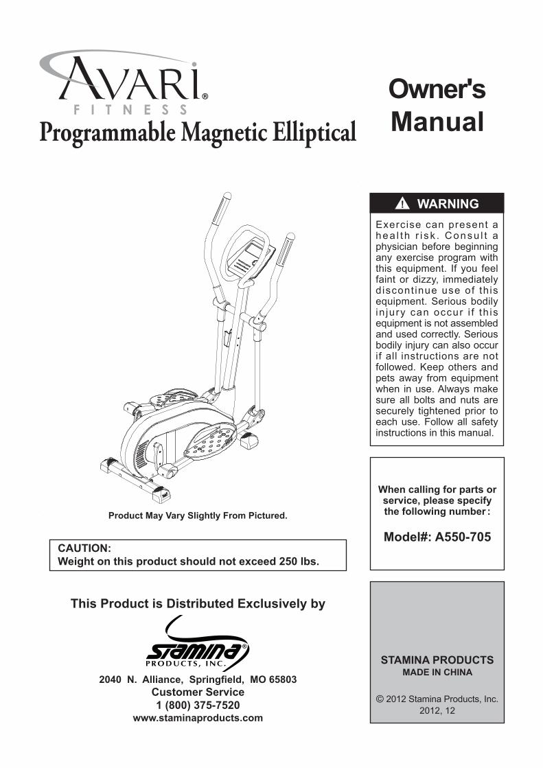
When calling for parts or service, please specify the following number :
Model#: A550-705CAUTION:Weight on this product should not exceed 250 lbs.
Owner'sManual
This Product is Distributed Exclusively by
2040 N. Alliance, Springfield, MO 65803Customer Service1 (800) 375-7520
www.staminaproducts.com
Product May Vary Slightly From Pictured.
STAMINA PRODUCTSMADE IN CHINA
© 2012 Stamina Products, Inc.2012, 12
Exercise can present a hea l t h r i s k . Consu l t a physician before beginning any exercise program with this equipment. If you feel faint or dizzy, immediately d iscont inue use of th is equipment. Serious bodily in jury can occur i f th is equipment is not assembled and used correctly. Serious bodily injury can also occur if all instructions are not followed. Keep others and pets away from equipment when in use. Always make sure all bolts and nuts are securely tightened prior to each use. Follow all safety instructions in this manual.
! WARNING
Programmable Magnetic Elliptical
SAFETY INSTRUCTIONS
2
1. Read all warnings and cautions posted on the AVARI® Programmable Magnetic Elliptical.2. The AVARI® Programmable Magnetic Elliptical should only be used after a thorough review of the
Owner’s Manual. Make sure that it is properly assembled and tightened before use.3. We recommend that two people be available for assembly of this product.4. Keep children away from the AVARI® Programmable Magnetic Elliptical. Do not allow children to use or
play on the AVARI® Programmable Magnetic Elliptical. Keep children and pets away from the AVARI® Programmable Magnetic Elliptical when it is in use.
5. It is recommended that you place this exercise equipment on an equipment mat.6. Set up and operate the AVARI® Programmable Magnetic Elliptical on a solid level surface. Do not
position the AVARI® Programmable Magnetic Elliptical on loose rugs or uneven surfaces.7. Make sure that adequate space is available for access to and around the AVARI® Programmable
Magnetic Elliptical.8. Adjust the Adjustable Endcaps(81) on the Rear Stabilizer(2) so that the AVARI® Programmable Magnetic
Elliptical sits on the floor without rocking.9. Before using, inspect the AVARI® Programmable Magnetic Elliptical for worn or loose components, and
securely tighten or replace any worn or loose components prior to use.10. Consult a physician prior to commencing an exercise program and follow his/her recommendations in
developing your fitness program. If at any time during exercise you feel faint, dizzy, or experience pain, stop and consult your physician.
11. Always choose the workout which best fits your physical strength and flexibility level. Know your limits and train within them. Always use common sense when exercising.
12. Do not wear loose or dangling clothing while using the AVARI® Programmable Magnetic Elliptical.13. Never exercise in bare feet or socks; always wear proper footwear such as running, walking, or cross
training shoes that fit well, provide foot support, and feature non-skid rubber soles.14. Be careful to maintain your balance while using, mounting, dismounting, or assembling the AVARI®
Programmable Magnetic Elliptical, loss of balance may result in a fall and serious bodily injury. Before mounting or dismounting, move the pedal on the mounting or dismounting side to its lowest position and bring the machine to a complete stop.
15. The AVARI® Programmable Magnetic Elliptical is not equipped with a free-wheel. Pedal speed should be reduced in a controlled manner.
16. The AVARI® Programmable Magnetic Elliptical should not be used by persons weighing over 250 pounds.
17. The AVARI® Programmable Magnetic Elliptical should be used by only one person at a time.18. The AVARI® Programmable Magnetic Elliptical is for consumer use only. It is not for use in public or
semipublic facilities.
! WARNING This product contains a chemical known to the State of California to cause cancer and birth defects or other reproductive harm. Consult your physician before starting this or any exercise program. This is especially important if you are over the age of 35, have never exercised before, are pregnant, or suffer from any health problem. This product is for home use only. Do not use in institutional or commercial applications. Failure to follow all warnings and instructions could result in serious injury or death. To reduce the risk of serious injury, read the following Safety Instructions before using the AVARI® Programmable Magnetic Elliptical.
! WARNING
! WARNING
TABLE OF CONTENTSSafety Instructions ...................................... 2Before You Begin ........................................ 4Equipment Warning, Caution & Notice Labels ... 5Hardware Identification Chart .................... 6Assembly Instructions ................................ 7Set Up Instructions .................................... 13Usage Guide ............................................... 14Operational Instructions ........................... 15Computer Instructions .............................. 16
Storage ....................................................... 25Maintenance ............................................... 25Conditioning Guidelines ........................... 26Warm-Up and Cool-Down ......................... 27Product Parts Drawing .............................. 28Parts List .................................................... 29Warranty ..................................................... 31Notes ........................................................... 32Fax/Mail Ordering Form ............................ 34

3
THANK YOU FOR PURCHASING THEAVARI® Programmable Magnetic Elliptical
To help you get started, we have pre-assembled most of yourAVARI® Programmable Magnetic Elliptical at the factory with the exception
of those few parts left unassembled for shipping purposes.Simply follow the few assembly instructions set forth in this manual.
With regular workouts, you will be getting your body into shapeand be on your way to achieving a happier and healthier lifestyle.
Should you have any questions,please call our Customer Service Department toll-free number,
1 (800) 375-7520Monday - Thursday, 7:30 A.M. - 5:00 P.M., Central Time.
Friday, 8:00 A.M. - 3:00 P.M., Central Time.
TELEPHONECUSTOMER SERVICETel: 1 (800) 375-7520
FAXCUSTOMER SERVICE
Fax: (417) 889-8064
MAILSTAMINA PRODUCTS, INC.
ATTN: Customer ServiceP.O. Box 1071
Springfield, MO. 65801-1071
ONLINECUSTOMER SERVICE
To enact your warranty, please register your productby going to register.staminaproducts.com
Call Us First
www.staminaproducts.com1 (800) 375-7520
Customer Service
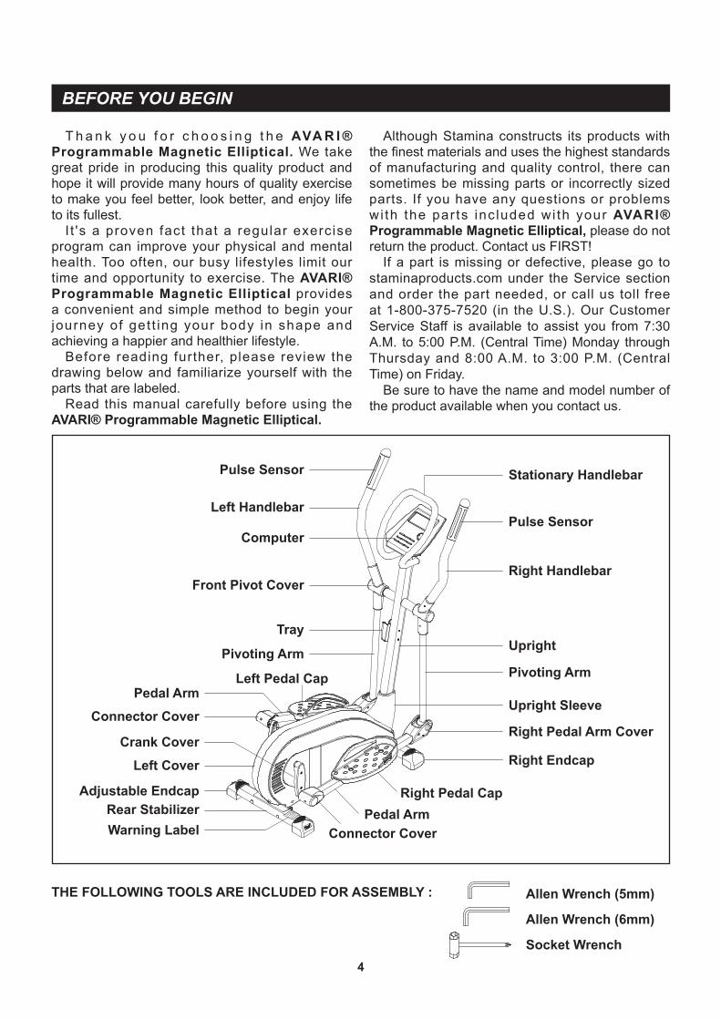
T h a n k y o u f o r c h o o s i n g t h e AVA R I ® Programmable Magnetic Elliptical. We take great pride in producing this quality product and hope it will provide many hours of quality exercise to make you feel better, look better, and enjoy life to its fullest.
I t 's a proven fact that a regular exercise program can improve your physical and mental health. Too often, our busy lifestyles limit our time and opportunity to exercise. The AVARI® Programmable Magnetic Elliptical provides a convenient and simple method to begin your journey of get t ing your body in shape and achieving a happier and healthier lifestyle.
Before reading further, please review the drawing below and familiarize yourself with the parts that are labeled.
Read this manual carefully before using the AVARI® Programmable Magnetic Elliptical.
BEFORE YOU BEGIN
Although Stamina constructs its products with the finest materials and uses the highest standards of manufacturing and quality control, there can sometimes be missing parts or incorrectly sized parts. If you have any questions or problems wi th the par ts inc luded wi th your AVARI® Programmable Magnetic Elliptical, please do not return the product. Contact us FIRST!
If a part is missing or defective, please go to staminaproducts.com under the Service section and order the part needed, or call us toll free at 1-800-375-7520 (in the U.S.). Our Customer Service Staff is available to assist you from 7:30 A.M. to 5:00 P.M. (Central Time) Monday through Thursday and 8:00 A.M. to 3:00 P.M. (Central Time) on Friday.
Be sure to have the name and model number of the product available when you contact us.
4
Right Handlebar
Upright
Computer
Pivoting Arm
Warning LabelPedal Arm
Right Pedal Cap
Right Endcap
Left Handlebar
Pivoting Arm
Left Pedal CapPedal Arm
Left Cover
Rear StabilizerAdjustable Endcap
Connector Cover
Pulse Sensor
Connector Cover
Right Pedal Arm Cover
Tray
Stationary Handlebar
Front Pivot Cover
Upright Sleeve
Crank Cover
THE FOLLOWING TOOLS ARE INCLUDED FOR ASSEMBLY : Allen Wrench (5mm)
Allen Wrench (6mm)
Socket Wrench
Pulse Sensor
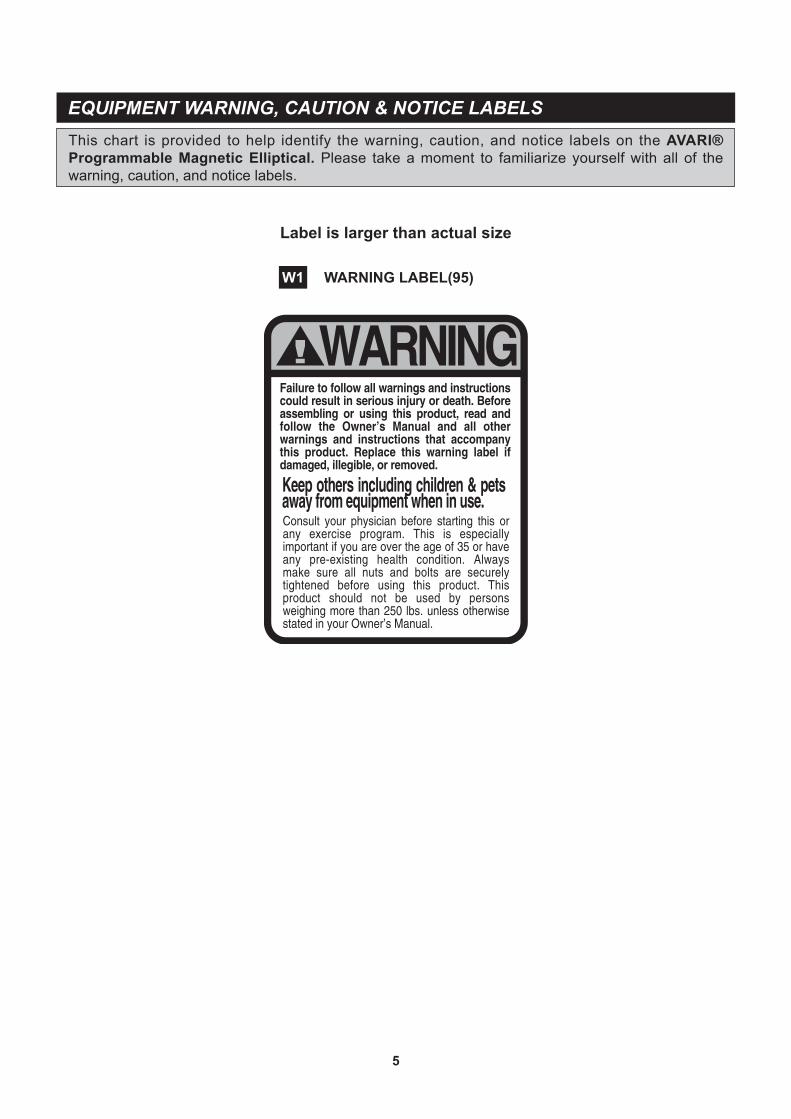
Label is larger than actual size
This chart is provided to help identify the warning, caution, and notice labels on the AVARI® Programmable Magnetic Elliptical. Please take a moment to familiarize yourself with all of the warning, caution, and notice labels.
EQUIPMENT WARNING, CAUTION & NOTICE LABELS
WARNING LABEL(95)W1
5
6
length
length
mm.
in.
INCHES
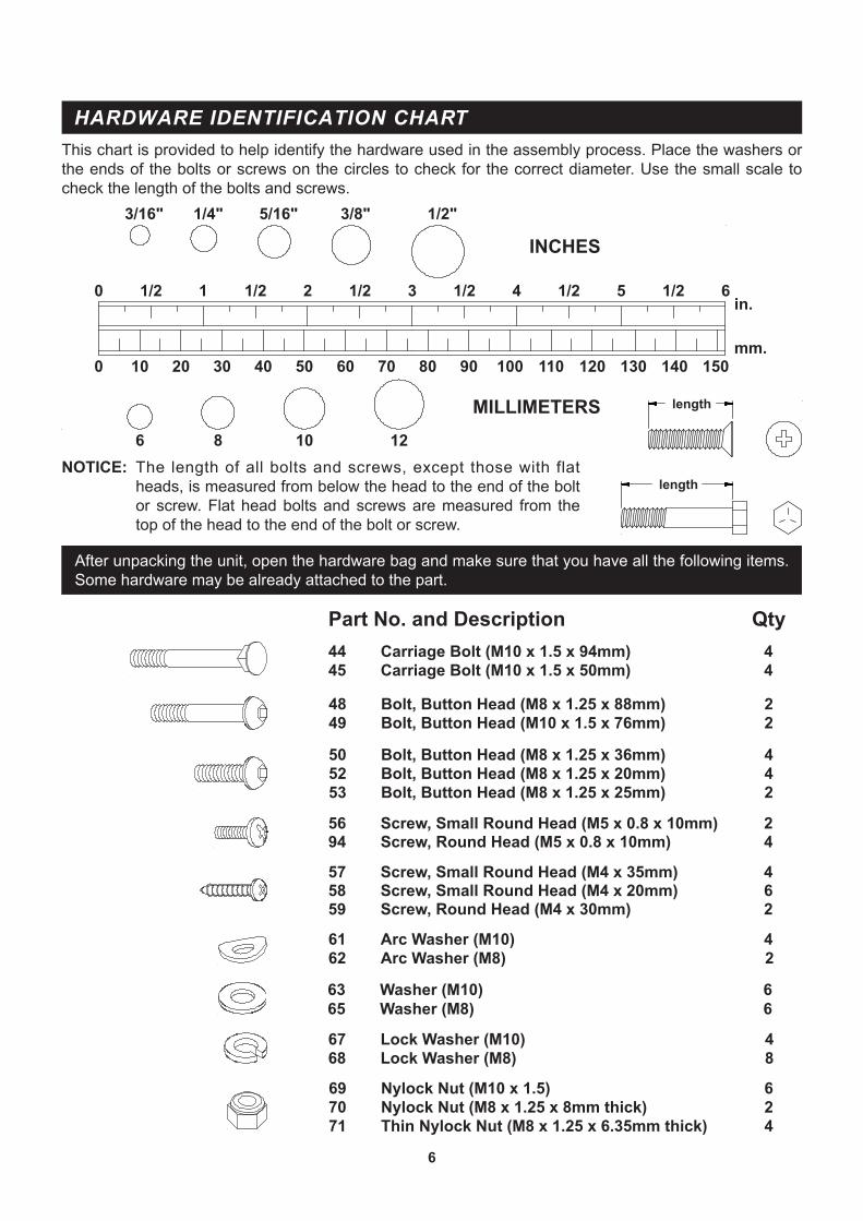
This chart is provided to help identify the hardware used in the assembly process. Place the washers or the ends of the bolts or screws on the circles to check for the correct diameter. Use the small scale to check the length of the bolts and screws.
NOTICE: The length of all bolts and screws, except those with flat heads, is measured from below the head to the end of the bolt or screw. Flat head bolts and screws are measured from the top of the head to the end of the bolt or screw.
After unpacking the unit, open the hardware bag and make sure that you have all the following items. Some hardware may be already attached to the part.
MILLIMETERS
0 10 20 30 40 50 60 70 80 90 100 110 120 130 140 150
0 1/2 1 1/2 2 1/2 3 1/2 4 1/2 5 1/2 6
6 8 10 12
3/16" 1/4" 5/16" 3/8" 1/2"
HARDWARE IDENTIFICATION CHART
Part No. and Description Qty
48 Bolt, Button Head (M8 x 1.25 x 88mm) 249 Bolt, Button Head (M10 x 1.5 x 76mm) 2
69 Nylock Nut (M10 x 1.5) 670 Nylock Nut (M8 x 1.25 x 8mm thick) 271 Thin Nylock Nut (M8 x 1.25 x 6.35mm thick) 4
67 Lock Washer (M10) 468 Lock Washer (M8) 8
61 Arc Washer (M10) 462 Arc Washer (M8) 2
63 Washer (M10) 665 Washer (M8) 6
44 Carriage Bolt (M10 x 1.5 x 94mm) 445 Carriage Bolt (M10 x 1.5 x 50mm) 4
57 Screw, Small Round Head (M4 x 35mm) 458 Screw, Small Round Head (M4 x 20mm) 659 Screw, Round Head (M4 x 30mm) 2
50 Bolt, Button Head (M8 x 1.25 x 36mm) 452 Bolt, Button Head (M8 x 1.25 x 20mm) 453 Bolt, Button Head (M8 x 1.25 x 25mm) 2
56 Screw, Small Round Head (M5 x 0.8 x 10mm) 294 Screw, Round Head (M5 x 0.8 x 10mm) 4
ASSEMBLY INSTRUCTIONS
7
A.
Dial
Dial
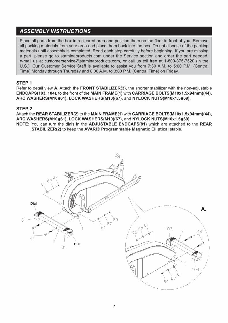
Place all parts from the box in a cleared area and position them on the floor in front of you. Remove all packing materials from your area and place them back into the box. Do not dispose of the packing materials until assembly is completed. Read each step carefully before beginning. If you are missing a part, please go to staminaproducts.com under the Service section and order the part needed, e-mail us at [email protected], or call us toll free at 1-800-375-7520 (in the U.S.). Our Customer Service Staff is available to assist you from 7:30 A.M. to 5:00 P.M. (Central Time) Monday through Thursday and 8:00 A.M. to 3:00 P.M. (Central Time) on Friday.
STEP 1Refer to detail view A. Attach the FRONT STABILIZER(3), the shorter stabilizer with the non-adjustable ENDCAPS(103, 104), to the front of the MAIN FRAME(1) with CARRIAGE BOLTS(M10x1.5x94mm)(44), ARC WASHERS(M10)(61), LOCK WASHERS(M10)(67), and NYLOCK NUTS(M10x1.5)(69).
STEP 2Attach the REAR STABILIZER(2) to the MAIN FRAME(1) with CARRIAGE BOLTS(M10x1.5x94mm)(44), ARC WASHERS(M10)(61), LOCK WASHERS(M10)(67), and NYLOCK NUTS(M10x1.5)(69).NOTE: You can turn the dials in the ADJUSTABLE ENDCAPS(81) which are attached to the REAR
STABILIZER(2) to keep the AVARI® Programmable Magnetic Elliptical stable.
ASSEMBLY INSTRUCTIONS
8
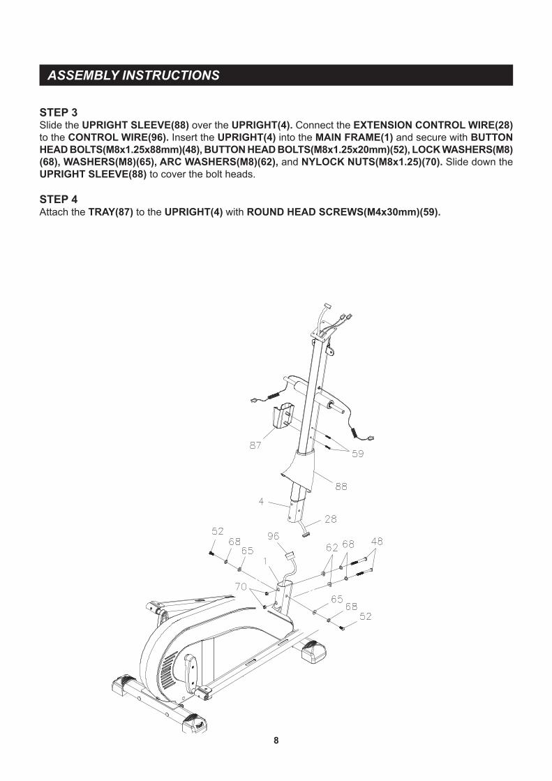
STEP 3Slide the UPRIGHT SLEEVE(88) over the UPRIGHT(4). Connect the EXTENSION CONTROL WIRE(28) to the CONTROL WIRE(96). Insert the UPRIGHT(4) into the MAIN FRAME(1) and secure with BUTTON HEAD BOLTS(M8x1.25x88mm)(48), BUTTON HEAD BOLTS(M8x1.25x20mm)(52), LOCK WASHERS(M8)(68), WASHERS(M8)(65), ARC WASHERS(M8)(62), and NYLOCK NUTS(M8x1.25)(70). Slide down the UPRIGHT SLEEVE(88) to cover the bolt heads.
STEP 4Attach the TRAY(87) to the UPRIGHT(4) with ROUND HEAD SCREWS(M4x30mm)(59).
ASSEMBLY INSTRUCTIONS
9
Tie
Tie
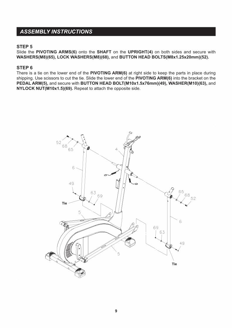
STEP 5Slide the PIVOTING ARMS(6) onto the SHAFT on the UPRIGHT(4) on both sides and secure with WASHERS(M8)(65), LOCK WASHERS(M8)(68), and BUTTON HEAD BOLTS(M8x1.25x20mm)(52).
STEP 6There is a tie on the lower end of the PIVOTING ARM(6) at right side to keep the parts in place during shipping. Use scissors to cut the tie. Slide the lower end of the PIVOTING ARM(6) into the bracket on the PEDAL ARM(5), and secure with BUTTON HEAD BOLT(M10x1.5x76mm)(49), WASHER(M10)(63), and NYLOCK NUT(M10x1.5)(69). Repeat to attach the opposite side.
ASSEMBLY INSTRUCTIONS
10
B.
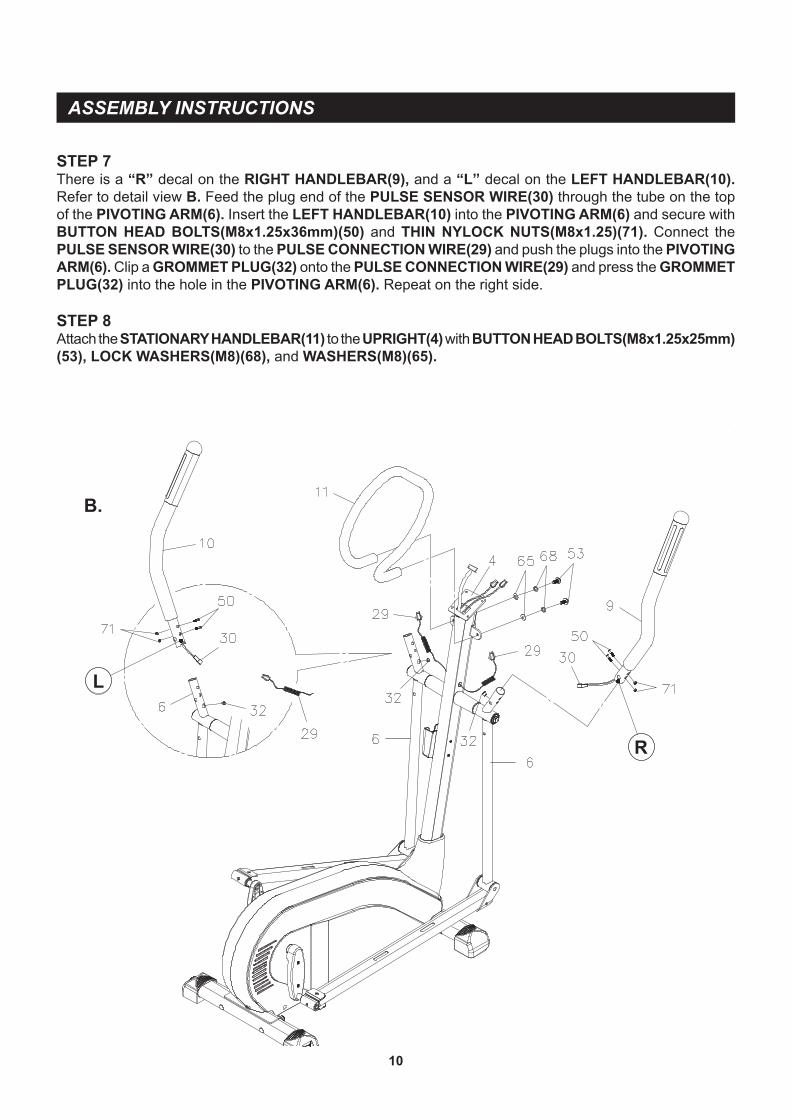
STEP 7There is a “R” decal on the RIGHT HANDLEBAR(9), and a “L” decal on the LEFT HANDLEBAR(10). Refer to detail view B. Feed the plug end of the PULSE SENSOR WIRE(30) through the tube on the top of the PIVOTING ARM(6). Insert the LEFT HANDLEBAR(10) into the PIVOTING ARM(6) and secure with BUTTON HEAD BOLTS(M8x1.25x36mm)(50) and THIN NYLOCK NUTS(M8x1.25)(71). Connect the PULSE SENSOR WIRE(30) to the PULSE CONNECTION WIRE(29) and push the plugs into the PIVOTING ARM(6). Clip a GROMMET PLUG(32) onto the PULSE CONNECTION WIRE(29) and press the GROMMET PLUG(32) into the hole in the PIVOTING ARM(6). Repeat on the right side.
STEP 8Attach the STATIONARY HANDLEBAR(11) to the UPRIGHT(4) with BUTTON HEAD BOLTS(M8x1.25x25mm)(53), LOCK WASHERS(M8)(68), and WASHERS(M8)(65).
L
R
ASSEMBLY INSTRUCTIONS
11
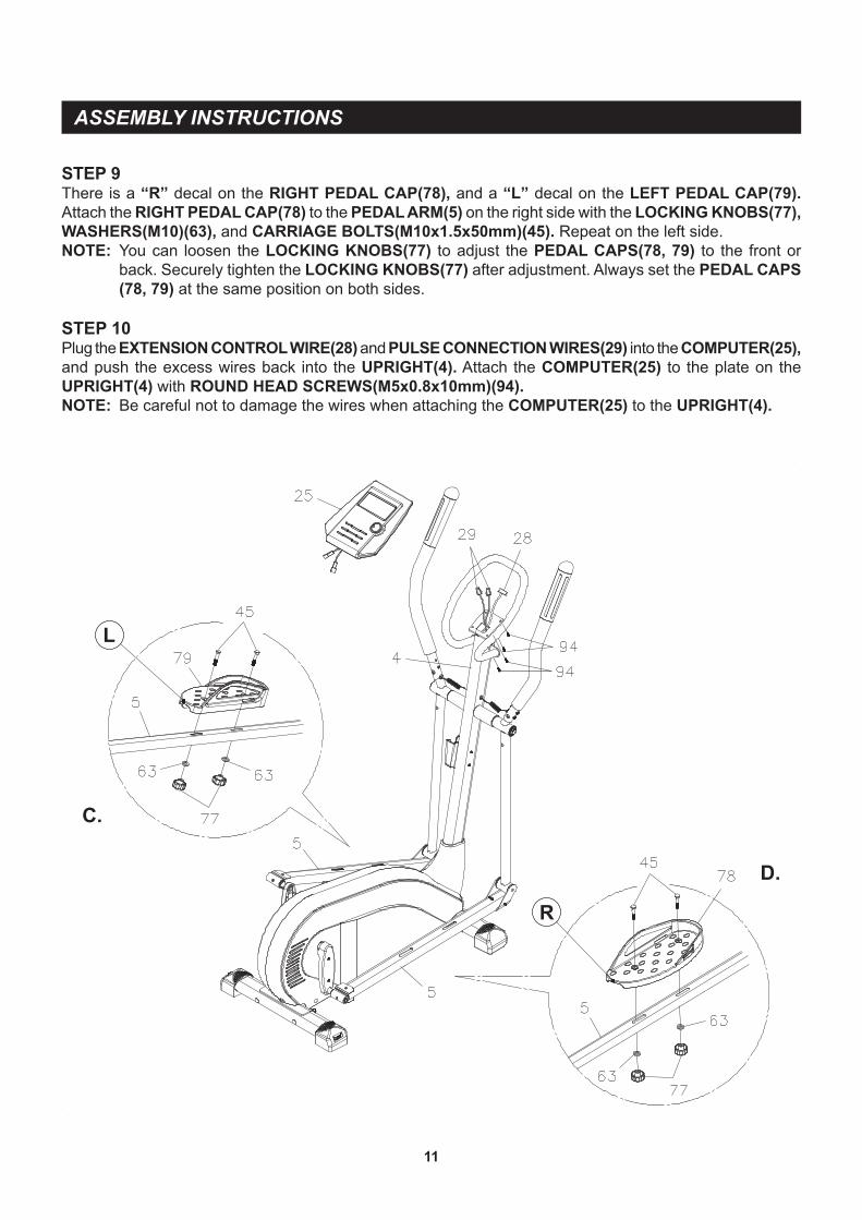
STEP 9There is a “R” decal on the RIGHT PEDAL CAP(78), and a “L” decal on the LEFT PEDAL CAP(79). Attach the RIGHT PEDAL CAP(78) to the PEDAL ARM(5) on the right side with the LOCKING KNOBS(77), WASHERS(M10)(63), and CARRIAGE BOLTS(M10x1.5x50mm)(45). Repeat on the left side.NOTE: You can loosen the LOCKING KNOBS(77) to adjust the PEDAL CAPS(78, 79) to the front or
back. Securely tighten the LOCKING KNOBS(77) after adjustment. Always set the PEDAL CAPS (78, 79) at the same position on both sides.
STEP 10Plug the EXTENSION CONTROL WIRE(28) and PULSE CONNECTION WIRES(29) into the COMPUTER(25), and push the excess wires back into the UPRIGHT(4). Attach the COMPUTER(25) to the plate on the UPRIGHT(4) with ROUND HEAD SCREWS(M5x0.8x10mm)(94).NOTE: Be careful not to damage the wires when attaching the COMPUTER(25) to the UPRIGHT(4).
C.
D.
L
R
ASSEMBLY INSTRUCTIONS
12
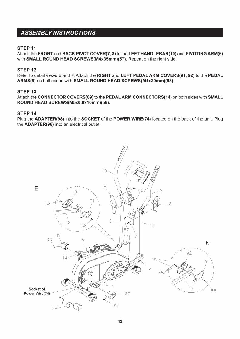
STEP 11Attach the FRONT and BACK PIVOT COVER(7, 8) to the LEFT HANDLEBAR(10) and PIVOTING ARM(6) with SMALL ROUND HEAD SCREWS(M4x35mm)(57). Repeat on the right side.
STEP 12Refer to detail views E and F. Attach the RIGHT and LEFT PEDAL ARM COVERS(91, 92) to the PEDAL ARMS(5) on both sides with SMALL ROUND HEAD SCREWS(M4x20mm)(58).
STEP 13Attach the CONNECTOR COVERS(89) to the PEDAL ARM CONNECTORS(14) on both sides with SMALL ROUND HEAD SCREWS(M5x0.8x10mm)(56).
STEP 14Plug the ADAPTER(98) into the SOCKET of the POWER WIRE(74) located on the back of the unit. Plug the ADAPTER(98) into an electrical outlet.
E.
F.
Socket ofPower Wire(74)
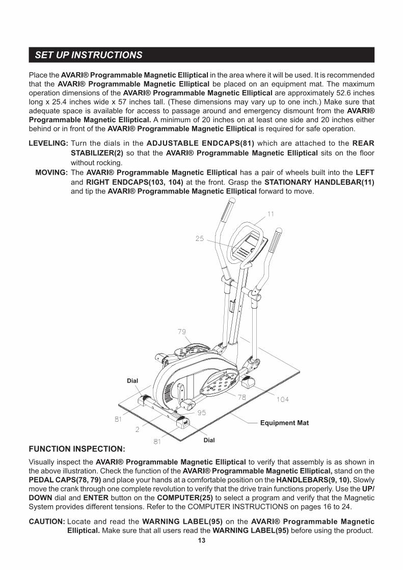
FUNCTION INSPECTION:Visually inspect the AVARI® Programmable Magnetic Elliptical to verify that assembly is as shown in the above illustration. Check the function of the AVARI® Programmable Magnetic Elliptical, stand on the PEDAL CAPS(78, 79) and place your hands at a comfortable position on the HANDLEBARS(9, 10). Slowly move the crank through one complete revolution to verify that the drive train functions properly. Use the UP/DOWN dial and ENTER button on the COMPUTER(25) to select a program and verify that the Magnetic System provides different tensions. Refer to the COMPUTER INSTRUCTIONS on pages 16 to 24.
CAUTION: Locate and read the WARNING LABEL(95) on the AVARI® Programmable Magnetic Elliptical. Make sure that all users read the WARNING LABEL(95) before using the product.
SET UP INSTRUCTIONS
13
Equipment Mat
Place the AVARI® Programmable Magnetic Elliptical in the area where it will be used. It is recommended that the AVARI® Programmable Magnetic Elliptical be placed on an equipment mat. The maximum operation dimensions of the AVARI® Programmable Magnetic Elliptical are approximately 52.6 inches long x 25.4 inches wide x 57 inches tall. (These dimensions may vary up to one inch.) Make sure that adequate space is available for access to passage around and emergency dismount from the AVARI® Programmable Magnetic Elliptical. A minimum of 20 inches on at least one side and 20 inches either behind or in front of the AVARI® Programmable Magnetic Elliptical is required for safe operation.
LEVELING: Turn the dials in the ADJUSTABLE ENDCAPS(81) which are attached to the REAR STABILIZER(2) so that the AVARI® Programmable Magnetic Elliptical sits on the floor without rocking.
MOVING: The AVARI® Programmable Magnetic Elliptical has a pair of wheels built into the LEFT and RIGHT ENDCAPS(103, 104) at the front. Grasp the STATIONARY HANDLEBAR(11) and tip the AVARI® Programmable Magnetic Elliptical forward to move.
Dial
Dial
14
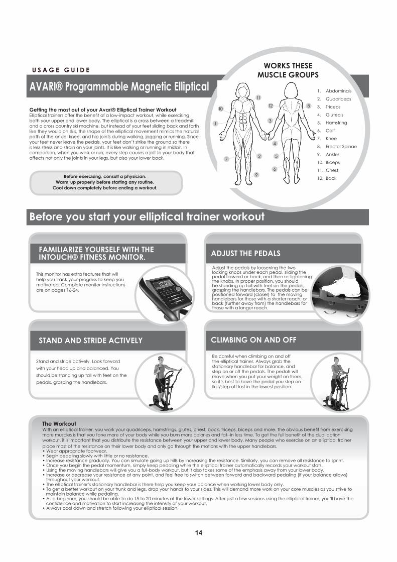
This monitor has extra features that willhelp you track your progress to keep youmotivated. Complete monitor instructionsare on pages 16-24.
AVARI® Programmable Magnetic Elliptical
OPERATIONAL INSTRUCTIONS
15
EXERCISE WORKOUTTo start using the AVARI® Programmable Magnetic Elliptical simply stand on the foot pedals with the front of your shoes close to the front edge of the pedal cap. Place your hands at a comfortable position on the handlebars. Simply move your highest foot forward and follow the natural path of the machine.
Start on a load level that is comfortable to familiarize yourself with the machine. Once you are comfortable, start adjusting the load level to achieve the workout desired.
Forward and ReverseThe AVARI® Programmable Magnetic Elliptical can be used in the forward and reverse direction to vary the muscles that you work out. This will also vary your workout, helping you to stay motivated. To change directions, simply slow the pedals down until they stop, and switch directions.
Load Level AdjustmentThe load level of AVARI® Programmable Magnetic Elliptical can be changed at any time during your workout. Adjusting your load level will allow you to increase or decrease your intensity level.
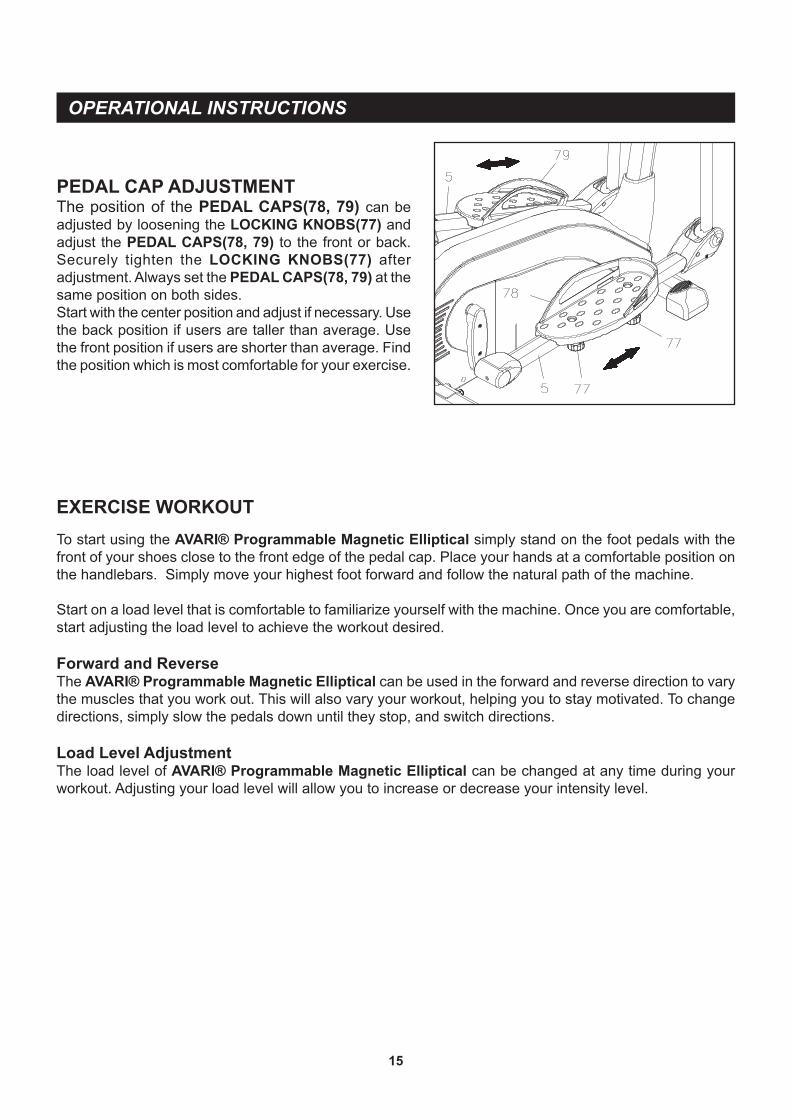
PEDAL CAP ADJUSTMENTThe position of the PEDAL CAPS(78, 79) can be adjusted by loosening the LOCKING KNOBS(77) and adjust the PEDAL CAPS(78, 79) to the front or back. Securely tighten the LOCKING KNOBS(77) after adjustment. Always set the PEDAL CAPS(78, 79) at the same position on both sides.Start with the center position and adjust if necessary. Use the back position if users are taller than average. Use the front position if users are shorter than average. Find the position which is most comfortable for your exercise.
16
ENTER :
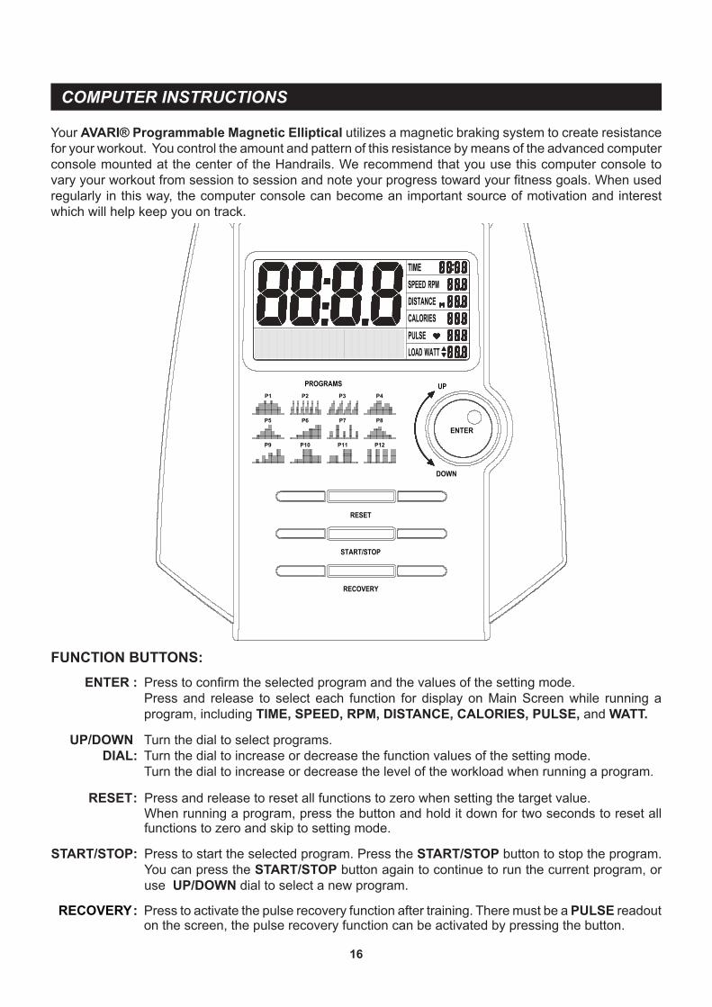
Press to start the selected program. Press the START/STOP button to stop the program. You can press the START/STOP button again to continue to run the current program, or use UP/DOWN dial to select a new program.
START/STOP:
Turn the dial to select programs.Turn the dial to increase or decrease the function values of the setting mode.Turn the dial to increase or decrease the level of the workload when running a program.
Your AVARI® Programmable Magnetic Elliptical utilizes a magnetic braking system to create resistance for your workout. You control the amount and pattern of this resistance by means of the advanced computer console mounted at the center of the Handrails. We recommend that you use this computer console to vary your workout from session to session and note your progress toward your fitness goals. When used regularly in this way, the computer console can become an important source of motivation and interest which will help keep you on track.
UP/DOWN DIAL:
Press to confirm the selected program and the values of the setting mode.Press and release to select each function for display on Main Screen while running a program, including TIME, SPEED, RPM, DISTANCE, CALORIES, PULSE, and WATT.
COMPUTER INSTRUCTIONS
FUNCTION BUTTONS:
RECOVERY :
P6
P1
P5
P2 P3
P7
P4
P8
P12P11P10P9
RESET : Press and release to reset all functions to zero when setting the target value.When running a program, press the button and hold it down for two seconds to reset all functions to zero and skip to setting mode.
Press to activate the pulse recovery function after training. There must be a PULSE readout on the screen, the pulse recovery function can be activated by pressing the button.
17
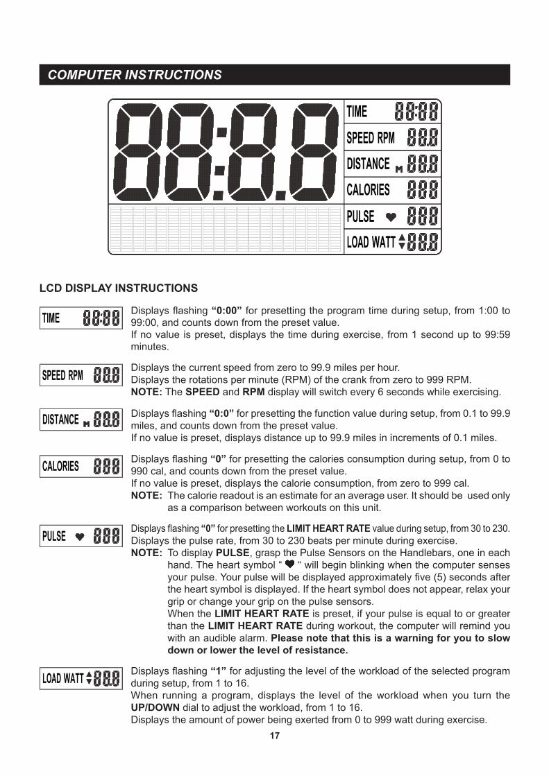
LCD DISPLAY INSTRUCTIONS
Displays the current speed from zero to 99.9 miles per hour.Displays the rotations per minute (RPM) of the crank from zero to 999 RPM.NOTE: The SPEED and RPM display will switch every 6 seconds while exercising.
Displays flashing “0:00” for presetting the program time during setup, from 1:00 to 99:00, and counts down from the preset value.If no value is preset, displays the time during exercise, from 1 second up to 99:59 minutes.
COMPUTER INSTRUCTIONS
Displays flashing “0:0” for presetting the function value during setup, from 0.1 to 99.9 miles, and counts down from the preset value.If no value is preset, displays distance up to 99.9 miles in increments of 0.1 miles.
Displays flashing “0” for presetting the LIMIT HEART RATE value during setup, from 30 to 230.Displays the pulse rate, from 30 to 230 beats per minute during exercise.NOTE: To display PULSE, grasp the Pulse Sensors on the Handlebars, one in each
hand. The heart symbol “ “ will begin blinking when the computer senses your pulse. Your pulse will be displayed approximately five (5) seconds after the heart symbol is displayed. If the heart symbol does not appear, relax your grip or change your grip on the pulse sensors.When the LIMIT HEART RATE is preset, if your pulse is equal to or greater than the LIMIT HEART RATE during workout, the computer will remind you with an audible alarm. Please note that this is a warning for you to slow down or lower the level of resistance.
Displays flashing “0” for presetting the calories consumption during setup, from 0 to 990 cal, and counts down from the preset value.If no value is preset, displays the calorie consumption, from zero to 999 cal.NOTE: The calorie readout is an estimate for an average user. It should be used only
as a comparison between workouts on this unit.
Displays flashing “1” for adjusting the level of the workload of the selected program during setup, from 1 to 16.When running a program, displays the level of the workload when you turn the UP/DOWN dial to adjust the workload, from 1 to 16.Displays the amount of power being exerted from 0 to 999 watt during exercise.

18
PROGRAM DESCRIPTIONS
(MAN.) MANUAL MANUAL PROGRAM: Program “MAN.” is a manual program allowing the user to have full manual control of the workload. Turn the UP/DOWN dial to increase or decrease the load.
PRESET PROGRAMS: Program “PROG” is a group of preset automatic programs, P01 to P12. The profiles are shown on the face of the computer. Turn the UP/DOWN dial to increase or decrease the load level of the program.
(P04) (P05)
(P07) (P08)
(P06)
(P09)
COMPUTER INSTRUCTIONS
(P01) (P02) (P03)
(P10) (P11) (P12)
USER SETTING PROGRAM: Program “USER” is an automatic program that allows the user to manually preset each of the 20 intervals. Under stop mode, use the UP/DOWN dial and ENTER button to edit the program profile. The program profile will be stored in the memory after setup. You can modify the profile anytime under the stop mode. NOTE: The changes can be stored only under stop mode.When running a program, you still can use the UP/DOWN dial to increase or decrease the load level of the program. These changes will not be stored in memory.
(USER) USER SETTING
(PROG) PRESET PROGRAMS
This computer contains 19 different programs. You can preset the program time and the computer will divide the time into 20 intervals. If you do not set the program time in advance, the computer will use the preset distance 0.1 mile for each interval to run the program.
19
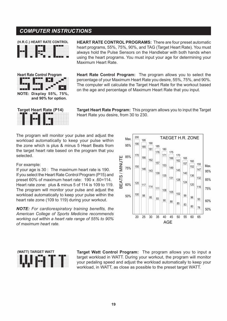
For example:If your age is 30 : The maximum heart rate is 190.If you select the Heart Rate Control Program (P15) and preset 60% of maximum heart rate: 190 x .60=114.Heart rate zone: plus & minus 5 of 114 is 109 to 119.The program will monitor your pulse and adjust the workload automatically to keep your pulse within the heart rate zone (109 to 119) during your workout.
The program will monitor your pulse and adjust the workload automatically to keep your pulse within the zone which is plus & minus 5 Heart Beats from the target heart rate based on the program that you selected.
COMPUTER INSTRUCTIONS
NOTE: For cardiorespiratory training benefits, the American College of Sports Medicine recommends working out within a heart rate range of 55% to 90% of maximum heart rate.
HEART RATE CONTROL PROGRAMS: There are four preset automatic heart programs, 55%, 75%, 90%, and TAG (Target Heart Rate). You must always hold the Pulse Sensors on the Handlebar with both hands when using the heart programs. You must input your age for determining your Maximum Heart Rate.
Target Heart Rate (P14)
Heart Rate Control Program: The program allows you to select the percentage of your Maximum Heart Rate you desire, 55%, 75%, and 90%. The computer will calculate the Target Heart Rate for the workout based on the age and percentage of Maximum Heart Rate that you input.
Target Heart Rate Program: This program allows you to input the Target Heart Rate you desire, from 30 to 230.
Heart Rate Control Program
(H.R.C.) HEART RATE CONTROL
Display 55%, 75%, and 90% for option.
NOTE:
(WATT) TARGET WATT Target Watt Control Program: The program allows you to input a target workload in WATT. During your workout, the program will monitor your pedaling speed and adjust the workload automatically to keep your workload, in WATT, as close as possible to the preset target WATT.
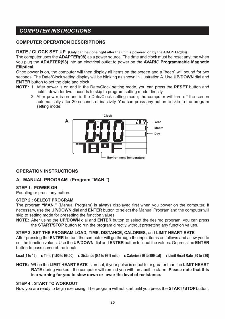
DATE / CLOCK SET UP (Only can be done right after the unit is powered on by the ADAPTER(98)).The computer uses the ADAPTER(98) as a power source. The date and clock must be reset anytime when you plug the ADAPTER(98) into an electrical outlet to power on the AVARI® Programmable Magnetic Elliptical.Once power is on, the computer will then display all items on the screen and a “beep” will sound for two seconds. The Date/Clock setting display will be blinking as shown in illustration A. Use UP/DOWN dial and ENTER button to set the date and clock.NOTE:
20
COMPUTER INSTRUCTIONS
COMPUTER OPERATION DESCRIPTIONS
A.
1. After power is on and in the Date/Clock setting mode, you can press the RESET button and hold it down for two seconds to skip to program setting mode directly.
2. After power is on and in the Date/Clock setting mode, the computer will turn off the screen automatically after 30 seconds of inactivity. You can press any button to skip to the program setting mode.
A. MANUAL PROGRAM (Program “MAN.”)STEP 1: POWER ONPedaling or press any button.
STEP 4 : START TO WORKOUTNow you are ready to begin exercising. The program will not start until you press the START / STOP button.
Load (1 to 16) Time (1:00 to 99:00) Distance (0.1 to 99.9 mile) Calories (10 to 990 cal) Limit Heart Rate (30 to 230)
NOTE: When the LIMIT HEART RATE is preset, if your pulse is equal to or greater than the LIMIT HEART RATE during workout, the computer will remind you with an audible alarm. Please note that this is a warning for you to slow down or lower the level of resistance.
OPERATION INSTRUCTIONS
STEP 2 : SELECT PROGRAMThe program “MAN.” (Manual Program) is always displayed first when you power on the computer. If necessary, use the UP/DOWN dial and ENTER button to select the Manual Program and the computer will skip to setting mode for presetting the function values.NOTE: After using the UP/DOWN dial and ENTER button to select the desired program, you can press
the START/STOP button to run the program directly without presetting any function values.
STEP 3: SET THE PROGRAM LOAD, TIME, DISTANCE, CALORIES, and LIMIT HEART RATEAfter pressing the ENTER button, the computer will go through the input items as follows and allow you to set the function values. Use the UP/DOWN dial and ENTER button to input the values. Or press the ENTER button to pass some of the inputs.
Year
Day
Month
Clock
Environment Temperature
21
COMPUTER INSTRUCTIONS
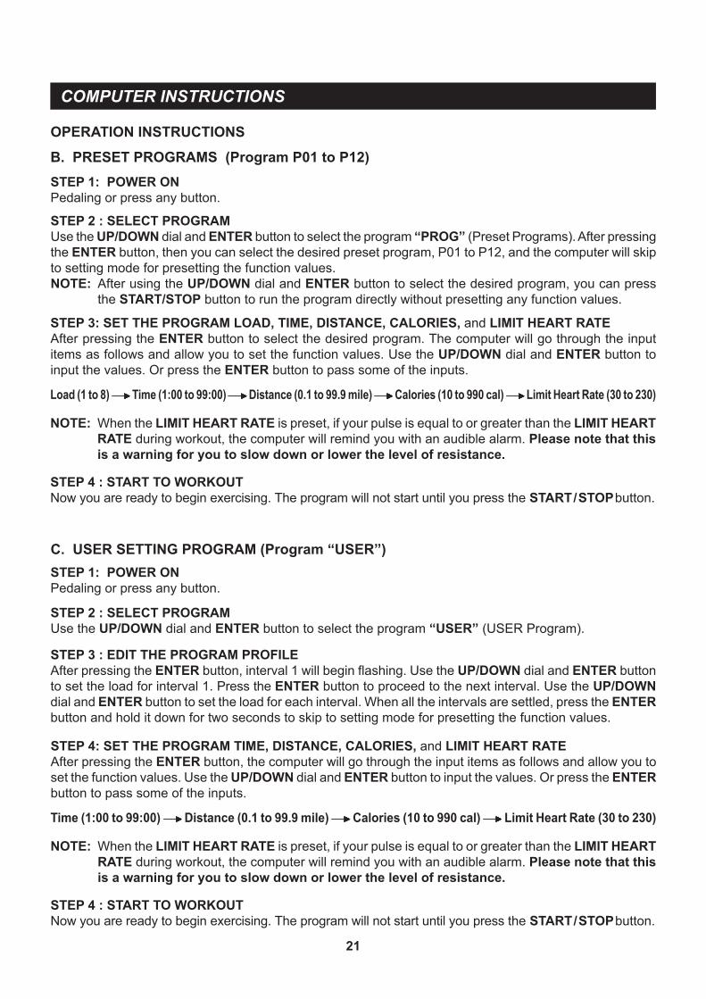
B. PRESET PROGRAMS (Program P01 to P12)STEP 1: POWER ONPedaling or press any button.
OPERATION INSTRUCTIONS
STEP 2 : SELECT PROGRAMUse the UP/DOWN dial and ENTER button to select the program “PROG” (Preset Programs). After pressing the ENTER button, then you can select the desired preset program, P01 to P12, and the computer will skip to setting mode for presetting the function values.NOTE: After using the UP/DOWN dial and ENTER button to select the desired program, you can press
the START/STOP button to run the program directly without presetting any function values.
STEP 4 : START TO WORKOUTNow you are ready to begin exercising. The program will not start until you press the START / STOP button.
Load (1 to 8) Time (1:00 to 99:00) Distance (0.1 to 99.9 mile) Calories (10 to 990 cal) Limit Heart Rate (30 to 230)
NOTE: When the LIMIT HEART RATE is preset, if your pulse is equal to or greater than the LIMIT HEART RATE during workout, the computer will remind you with an audible alarm. Please note that this is a warning for you to slow down or lower the level of resistance.
STEP 3: SET THE PROGRAM LOAD, TIME, DISTANCE, CALORIES, and LIMIT HEART RATEAfter pressing the ENTER button to select the desired program. The computer will go through the input items as follows and allow you to set the function values. Use the UP/DOWN dial and ENTER button to input the values. Or press the ENTER button to pass some of the inputs.
C. USER SETTING PROGRAM (Program “USER”)
STEP 3 : EDIT THE PROGRAM PROFILEAfter pressing the ENTER button, interval 1 will begin flashing. Use the UP/DOWN dial and ENTER button to set the load for interval 1. Press the ENTER button to proceed to the next interval. Use the UP/DOWN dial and ENTER button to set the load for each interval. When all the intervals are settled, press the ENTER button and hold it down for two seconds to skip to setting mode for presetting the function values.
STEP 1: POWER ONPedaling or press any button.
STEP 2 : SELECT PROGRAMUse the UP/DOWN dial and ENTER button to select the program “USER” (USER Program).
STEP 4 : START TO WORKOUTNow you are ready to begin exercising. The program will not start until you press the START / STOP button.
Time (1:00 to 99:00) Distance (0.1 to 99.9 mile) Calories (10 to 990 cal) Limit Heart Rate (30 to 230)
NOTE: When the LIMIT HEART RATE is preset, if your pulse is equal to or greater than the LIMIT HEART RATE during workout, the computer will remind you with an audible alarm. Please note that this is a warning for you to slow down or lower the level of resistance.
STEP 4: SET THE PROGRAM TIME, DISTANCE, CALORIES, and LIMIT HEART RATEAfter pressing the ENTER button, the computer will go through the input items as follows and allow you to set the function values. Use the UP/DOWN dial and ENTER button to input the values. Or press the ENTER button to pass some of the inputs.
COMPUTER INSTRUCTIONS
22
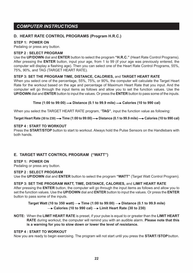
D. HEART RATE CONTROL PROGRAMS (Program H.R.C.)
STEP 3: SET THE PROGRAM TIME, DISTANCE, CALORIES, and TARGET HEART RATEWhen you select one of the percentage, 55%, 75%, or 90%, the computer will calculate the Target Heart Rate for the workout based on the age and percentage of Maximum Heart Rate that you input. And the computer will go through the input items as follows and allow you to set the function values. Use the UP/DOWN dial and ENTER button to input the values. Or press the ENTER button to pass some of the inputs.
STEP 4 : START TO WORKOUTPress the START/STOP button to start to workout. Always hold the Pulse Sensors on the Handlebars with both hands.
STEP 1: POWER ONPedaling or press any button.
Target Heart Rate (30 to 230) Time (1:00 to 99:00) Distance (0.1 to 99.9 mile) Calories (10 to 990 cal)
When you select the TARGET HEART RATE program, “TAG”, input the function value as following:
Time (1:00 to 99:00) Distance (0.1 to 99.9 mile) Calories (10 to 990 cal)
E. TARGET WATT CONTROL PROGRAM (“WATT”)STEP 1: POWER ONPedaling or press any button.
STEP 4 : START TO WORKOUTNow you are ready to begin exercising. The program will not start until you press the START / STOP button.
Target Watt (10 to 350 watt) Time (1:00 to 99:00) Distance (0.1 to 99.9 mile) Calories (10 to 990 cal) Limit Heart Rate (30 to 230)
NOTE: When the LIMIT HEART RATE is preset, if your pulse is equal to or greater than the LIMIT HEART RATE during workout, the computer will remind you with an audible alarm. Please note that this is a warning for you to slow down or lower the level of resistance.
STEP 2 : SELECT PROGRAMUse the UP/DOWN dial and ENTER button to select the program “WATT” (Target Watt Control Program).
STEP 3: SET THE PROGRAM WATT, TIME, DISTANCE, CALORIES, and LIMIT HEART RATEAfter pressing the ENTER button, the computer will go through the input items as follows and allow you to set the function values. Use the UP/DOWN dial and ENTER button to input the values. Or press the ENTER button to pass some of the inputs.
STEP 2 : SELECT PROGRAMUse the UP/DOWN dial and ENTER button to select the program “H.R.C.” (Heart Rate Control Programs). After pressing the ENTER button, input your age, from 1 to 99 (if your age was previously entered, the computer will display a flashing age). Then you can select one of the Heart Rate Control Programs, 55%, 75%, 90%, and TAG (TARGET HEART RATE).
COMPUTER INSTRUCTIONS
23
OPERATION DESCRIPTIONS
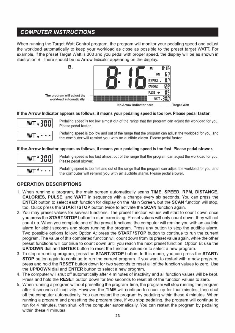
B.
Target WattNo Arrow Indicator here
The program will adjust the workload automatically.
If the Arrow Indicator appears as follows, it means your pedaling speed is too low. Please pedal faster.Pedaling speed is too low almost out of the range that the program can adjust the workload for you. Please pedal faster.
Pedaling speed is too low and out of the range that the program can adjust the workload for you, and the computer will remind you with an audible alarm. Please pedal faster.
If the Arrow Indicator appears as follows, it means your pedaling speed is too fast. Please pedal slower.Pedaling speed is too fast almost out of the range that the program can adjust the workload for you. Please pedal slower.
Pedaling speed is too fast and out of the range that the program can adjust the workload for you, and the computer will remind you with an audible alarm. Please pedal slower.
1. When running a program, the main screen automatically scans TIME, SPEED, RPM, DISTANCE, CALORIES, PULSE, and WATT in sequence with a change every six seconds. You can press the ENTER button to select each function for display on the Main Screen, but the SCAN function will stop, too. Quick press the START / STOP button twice to activate the SCAN function again.
2. You may preset values for several functions. The preset function values will start to count down once you press the START / STOP button to start exercising. Preset values will only count down, they will not count up. When you complete one of the preset functions, the computer will remind you with an audible alarm for eight seconds and stops running the program. Press any button to stop the audible alarm. Two possible options follow: Option A: press the START / STOP button to continue to run the current program. The value of this completed function will count down from its preset value again, while the other preset functions will continue to count down until you reach the next preset function. Option B: use the UP/DOWN dial and ENTER button to reset the function values or to select a new program.
3. To stop a running program, press the START / STOP button. In this mode, you can press the START /
STOP button again to continue to run the current program. If you want to restart with a new program, press and hold the RESET button down for two seconds to reset all of the function values to zero. Use the UP/DOWN dial and ENTER button to select a new program.
4. The computer will shut off automatically after 4 minutes of inactivity and all function values will be kept. Press and hold the RESET button down for two seconds to reset all of the function values to zero.
5. When running a program without presetting the program time, the program will stop running the program after 4 seconds of inactivity. However, the TIME will continue to count up for four minutes, then shut off the computer automatically. You can restart the program by pedaling within these 4 minutes. When running a program and presetting the program time, if you stop pedaling, the program will continue to run for 4 minutes, then shut off the computer automatically. You can restart the program by pedaling within these 4 minutes.
When running the Target Watt Control program, the program will monitor your pedaling speed and adjust the workload automatically to keep your workload as close as possible to the preset target WATT. For example, if the preset Target Watt is 300 and you pedal with proper speed, the display will be as shown in illustration B. There should be no Arrow Indicator appearing on the display.
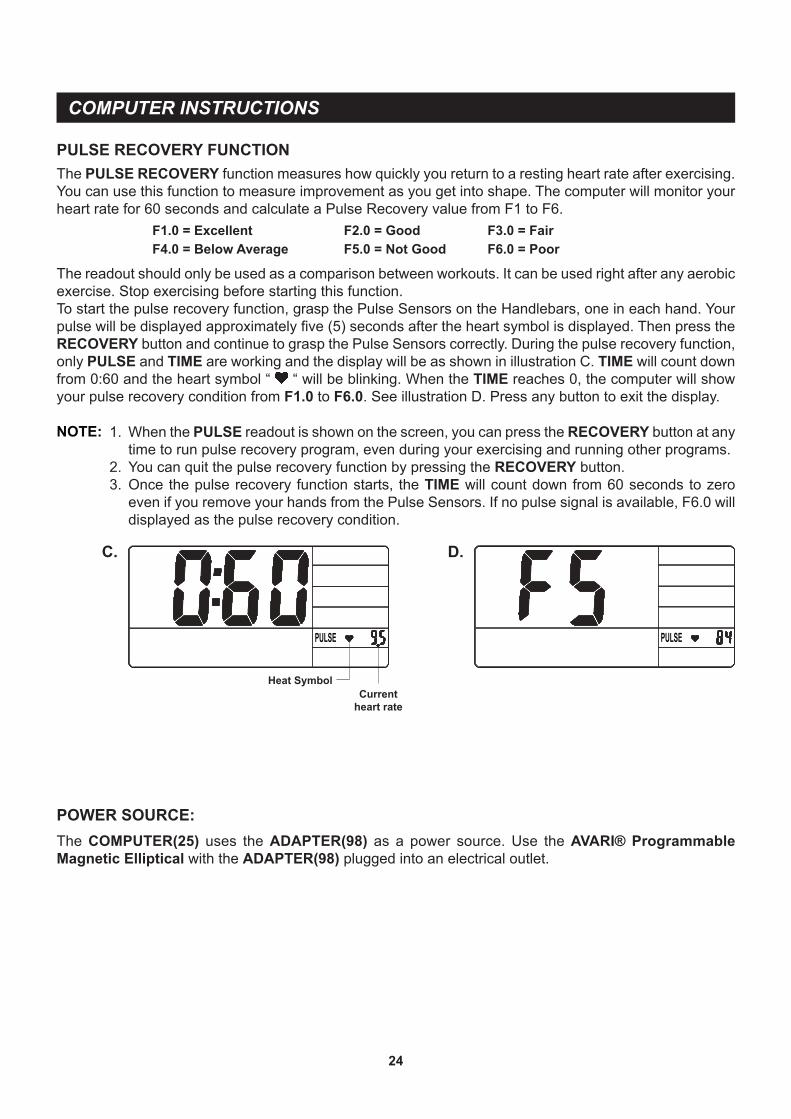
The readout should only be used as a comparison between workouts. It can be used right after any aerobic exercise. Stop exercising before starting this function.To start the pulse recovery function, grasp the Pulse Sensors on the Handlebars, one in each hand. Your pulse will be displayed approximately five (5) seconds after the heart symbol is displayed. Then press the RECOVERY button and continue to grasp the Pulse Sensors correctly. During the pulse recovery function, only PULSE and TIME are working and the display will be as shown in illustration C. TIME will count down from 0:60 and the heart symbol “ “ will be blinking. When the TIME reaches 0, the computer will show your pulse recovery condition from F1.0 to F6.0. See illustration D. Press any button to exit the display.
NOTE:
COMPUTER INSTRUCTIONS
24
The PULSE RECOVERY function measures how quickly you return to a resting heart rate after exercising. You can use this function to measure improvement as you get into shape. The computer will monitor your heart rate for 60 seconds and calculate a Pulse Recovery value from F1 to F6. F1.0 = Excellent F2.0 = Good F3.0 = Fair F4.0 = Below Average F5.0 = Not Good F6.0 = Poor
C. D.
PULSE RECOVERY FUNCTION
Currentheart rate
Heat Symbol
POWER SOURCE:
1. When the PULSE readout is shown on the screen, you can press the RECOVERY button at any time to run pulse recovery program, even during your exercising and running other programs.
2. You can quit the pulse recovery function by pressing the RECOVERY button.3. Once the pulse recovery function starts, the TIME will count down from 60 seconds to zero
even if you remove your hands from the Pulse Sensors. If no pulse signal is available, F6.0 will displayed as the pulse recovery condition.
The COMPUTER(25) uses the ADAPTER(98) as a power source. Use the AVARI® Programmable Magnetic Elliptical with the ADAPTER(98) plugged into an electrical outlet.
25
1. To store the AVARI® Programmable Magnetic Elliptical, simply keep it in a clean dry place.2. The minimum rest dimensions of the AVARI® Programmable Magnetic Elliptical are approximately
48 inches long x 25.4 inches wide x 60 inches tall. These dimensions may vary. Please measure your AVARI® Programmable Magnetic Elliptical if exact dimensions are needed.
3. Move the AVARI® Programmable Magnetic Elliptical with the moving wheels on the FRONT STABILIZER(3). Grasp the STATIONARY HANDLEBAR(11) on the UPRIGHT(4), tip the AVARI® Programmable Magnetic Elliptical forward and move slowly.
STORAGE
The safety and integrity designed into the AVARI® Programmable Magnetic Elliptical can only be maintained when the AVARI® Programmable Magnetic Elliptical is regularly examined for damage and wear. Special attention should be given to the following:
MAINTENANCE
1. Use the UP/DOWN dial and ENTER button on the COMPUTER(25) to select a program and verify that the MAGNETIC UNIT(17) provides different tensions. The MAGNETIC UNIT(17) should provide many years of use.
2. Verify that all nuts and bolts are present and properly tightened. Replace missing nuts and bolts. Tighten loose nuts and bolts.
3. Verify that the WARNING LABEL(95) is in place and easy to read. Call Stamina Products immediately at 1-800-375-7520 for a replacement WARNING LABEL(95) if it is missing or damaged.
4. It is the sole responsibility of the user/owner to ensure that regular maintenance is performed.5. Worn or damaged components shall be replaced immediately or the AVARI® Programmable
Magnetic Elliptical removed from service until repair is made.6. Only Stamina Products supplied components shall be used to maintain/repair the AVARI®
Programmable Magnetic Elliptical.7. Keep your AVARI® Programmable Magnetic Elliptical clean by wiping it off with an absorbent cloth
after use.
How you begin your exercise program depends on your physical condition. If you have been inactive for several years or are severely overweight, start slowly and increase your workout time gradually. Increase your workout intensity gradually by monitoring your heart rate while you exercise.
Initially you may only be able to exercise within your target zone for a few minutes; however, your aerobic capacity will improve over the next six to eight weeks. It is important to pace yourself while you exercise so you don't tire too quickly.
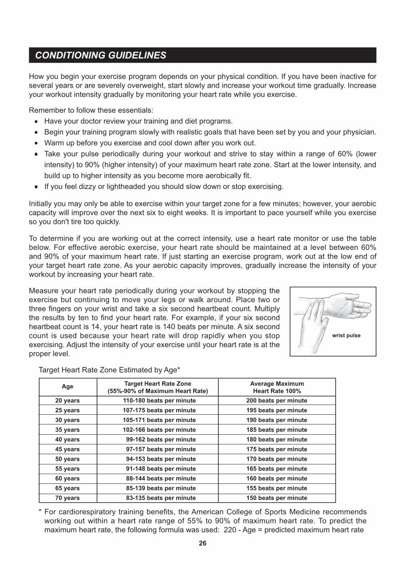
Measure your heart rate periodically during your workout by stopping the exercise but continuing to move your legs or walk around. Place two or three fingers on your wrist and take a six second heartbeat count. Multiply the results by ten to find your heart rate. For example, if your six second heartbeat count is 14, your heart rate is 140 beats per minute. A six second count is used because your heart rate will drop rapidly when you stop exercising. Adjust the intensity of your exercise until your heart rate is at the proper level.
wrist pulse
Remember to follow these essentials: Have your doctor review your training and diet programs. Begin your training program slowly with realistic goals that have been set by you and your physician. Warm up before you exercise and cool down after you work out. Take your pulse periodically during your workout and strive to stay within a range of 60% (lower
intensity) to 90% (higher intensity) of your maximum heart rate zone. Start at the lower intensity, and build up to higher intensity as you become more aerobically fit.
If you feel dizzy or lightheaded you should slow down or stop exercising.
To determine if you are working out at the correct intensity, use a heart rate monitor or use the table below. For effective aerobic exercise, your heart rate should be maintained at a level between 60% and 90% of your maximum heart rate. If just starting an exercise program, work out at the low end of your target heart rate zone. As your aerobic capacity improves, gradually increase the intensity of your workout by increasing your heart rate.
CONDITIONING GUIDELINES
Target Heart Rate Zone Estimated by Age*
* For cardiorespiratory training benefits, the American College of Sports Medicine recommends working out within a heart rate range of 55% to 90% of maximum heart rate. To predict the maximum heart rate, the following formula was used: 220 - Age = predicted maximum heart rate
20 years25 years30 years35 years40 years45 years50 years55 years60 years65 years70 years
Average MaximumHeart Rate 100%
Age
110-180 beats per minute107-175 beats per minute105-171 beats per minute102-166 beats per minute99-162 beats per minute97-157 beats per minute94-153 beats per minute91-148 beats per minute88-144 beats per minute85-139 beats per minute83-135 beats per minute
200 beats per minute195 beats per minute190 beats per minute185 beats per minute180 beats per minute175 beats per minute170 beats per minute165 beats per minute160 beats per minute155 beats per minute150 beats per minute
Target Heart Rate Zone(55%-90% of Maximum Heart Rate)
26
WARM-UP and COOL-DOWN
Warm-Up The purpose of warming up is to prepare your body for exercise and to minimize injuries. Warm up for two to five minutes before strength training or aerobic exercising. Perform activities that raise your heart rate and warm the working muscles. Activities may include brisk walking, jogging, jumping jacks, jump rope, and running in place.
Stretching Stretching while your muscles are warm after a proper warm-up and again after your strength or aerobic training session is very important. Muscles stretch more easily at these times because of their elevated temperature, which greatly reduces the risk of injury. Stretches should be held for 15 to 30 seconds. Do not bounce.
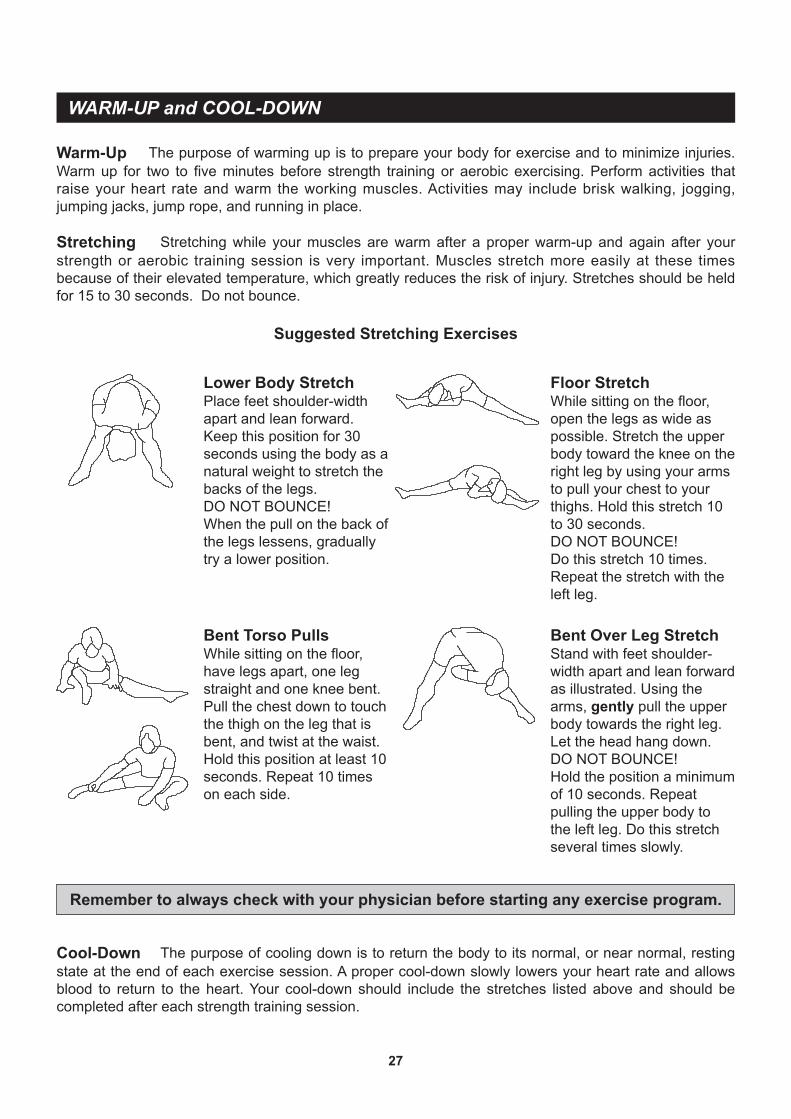
Suggested Stretching Exercises
Remember to always check with your physician before starting any exercise program.
Cool-Down The purpose of cooling down is to return the body to its normal, or near normal, resting state at the end of each exercise session. A proper cool-down slowly lowers your heart rate and allows blood to return to the heart. Your cool-down should include the stretches listed above and should be completed after each strength training session.
Lower Body StretchPlace feet shoulder-width apart and lean forward.Keep this position for 30 seconds using the body as a natural weight to stretch the backs of the legs.DO NOT BOUNCE!When the pull on the back of the legs lessens, gradually try a lower position.
Floor StretchWhile sitting on the floor, open the legs as wide as possible. Stretch the upper body toward the knee on the right leg by using your arms to pull your chest to your thighs. Hold this stretch 10 to 30 seconds.DO NOT BOUNCE!Do this stretch 10 times. Repeat the stretch with the left leg.
Bent Over Leg StretchStand with feet shoulder-width apart and lean forward as illustrated. Using the arms, gently pull the upper body towards the right leg. Let the head hang down.DO NOT BOUNCE!Hold the position a minimum of 10 seconds. Repeat pulling the upper body to the left leg. Do this stretch several times slowly.
Bent Torso PullsWhile sitting on the floor, have legs apart, one leg straight and one knee bent. Pull the chest down to touch the thigh on the leg that is bent, and twist at the waist. Hold this position at least 10 seconds. Repeat 10 times on each side.
27
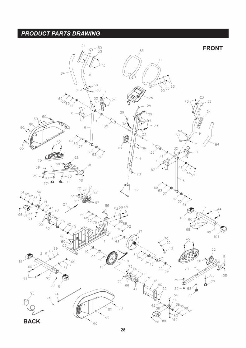
PRODUCT PARTS DRAWING
28
FRONT
BACK
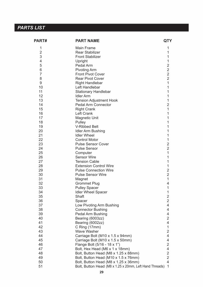
PART# PART NAME QTY
PARTS LIST
29
1 Main Frame 1 2 Rear Stabilizer 1 3 Front Stabilizer 1 4 Upright 1 5 Pedal Arm 2 6 Pivoting Arm 2 7 Front Pivot Cover 2 8 Rear Pivot Cover 2 9 Right Handlebar 1 10 Left Handlebar 1 11 Stationary Handlebar 1 12 Idler Arm 1 13 Tension Adjustment Hook 1 14 Pedal Arm Connector 2 15 Right Crank 1 16 Left Crank 1 17 Magnetic Unit 1 18 Pulley 1 19 V-Ribbed Belt 1 20 Idler Arm Bushing 1 21 Idler Wheel 1 22 Control Motor 1 23 Pulse Sensor Cover 2 24 Pulse Sensor 2 25 Computer 1 26 Sensor Wire 1 27 Tension Cable 1 28 Extension Control Wire 1 29 Pulse Connection Wire 2 30 Pulse Sensor Wire 2 31 Magnet 1 32 Grommet Plug 4 33 Pulley Spacer 1 34 Idler Wheel Spacer 1 35 Shaft 2 36 Spacer 2 37 Low Pivoting Arm Bushing 4 38 Connector Bushing 4 39 Pedal Arm Bushing 4 40 Bearing (6003zz) 2 41 Bearing (6002zz) 4 42 C Ring (17mm) 1 43 Wave Washer 2 44 Carriage Bolt (M10 x 1.5 x 94mm) 4 45 Carriage Bolt (M10 x 1.5 x 50mm) 4 46 Flange Bolt (5/16 - 18 x 1”) 2 47 Bolt, Hex Head (M6 x 1 x 18mm) 4 48 Bolt, Button Head (M8 x 1.25 x 88mm) 2 49 Bolt, Button Head (M10 x 1.5 x 76mm) 2 50 Bolt, Button Head (M8 x 1.25 x 36mm) 4 51 Bolt, Button Head (M8 x 1.25 x 20mm, Left Hand Threads) 1
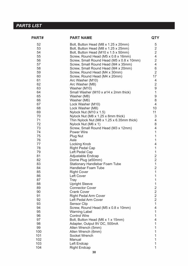
PARTS LIST
30
52 Bolt, Button Head (M8 x 1.25 x 20mm) 5 53 Bolt, Button Head (M8 x 1.25 x 25mm) 2 54 Bolt, Button Head (M10 x 1.5 x 50mm) 2 55 Screw, Round Head (M5 x 0.8 x 16mm) 4 56 Screw, Small Round Head (M5 x 0.8 x 10mm) 2 57 Screw, Small Round Head (M4 x 35mm) 4 58 Screw, Small Round Head (M4 x 20mm) 6 59 Screw, Round Head (M4 x 30mm) 2 60 Screw, Round Head (M4 x 20mm) 17 61 Arc Washer (M10) 4 62 Arc Washer (M8) 2 63 Washer (M10) 9 64 Small Washer (M10 x ø14 x 2mm thick) 1 65 Washer (M8) 9 66 Washer (M6) 8 67 Lock Washer (M10) 4 68 Lock Washer (M8) 10 69 Nylock Nut (M10 x 1.5) 11 70 Nylock Nut (M8 x 1.25 x 8mm thick) 3 71 Thin Nylock Nut (M8 x 1.25 x 6.35mm thick) 4 72 Nylock Nut (M6 x 1) 8 73 Screw, Small Round Head (M3 x 12mm) 4 74 Power Wire 1 75 Plug Nut 1 76 Axle 1 77 Locking Knob 4 78 Right Pedal Cap 1 79 Left Pedal Cap 1 81 Adjustable Endcap 2 82 Dome Plug (ø50mm) 2 83 Stationary Handlebar Foam Tube 1 84 Handlebar Foam Tube 2 85 Right Cover 1 86 Left Cover 1 87 Tray 1 88 Upright Sleeve 1 89 Connector Cover 2 90 Crank Cover 2 91 Right Pedal Arm Cover 2 92 Left Pedal Arm Cover 2 93 Sensor Clip 1 94 Screw, Round Head (M5 x 0.8 x 10mm) 4 95 Warning Label 1 96 Control Wire 1 97 Bolt, Button Head (M6 x 1 x 15mm) 4 98 Adapter, Output 9V DC, 500mA 1 99 Allen Wrench (5mm) 1 100 Allen Wrench (6mm) 1 101 Socket Wrench 1 102 Manual 1 103 Left Endcap 1 104 Right Endcap 1
PART# PART NAME QTY

LIMITED WARRANTY
WARRANTY
MODEL A550-705
31
Stamina Products, Inc. warrants that this product will be free from defects in materials and workmanship under normal use, service, proper assembly and proper operation for a period of 90 days on the parts and three years on the frame from the date of the original purchase from an authorized retailer. THIS WARRANTY SHALL NOT APPLY TO ANY PRODUCT WHICH HAS BEEN SUBJECT TO COMMERCIAL USE, ABUSE, MISUSE, ALTERATION OF ANY TYPE OR CAUSE OR TO ANY DEFECT OR DAMAGE CAUSED BY IMPROPER ASSEMBLY, REPAIR, REPLACEMENT, SUBSTITUTION OR USE WITH PARTS OTHER THAN PARTS PROVIDED BY STAMINA PRODUCTS, INC. Commercial use includes use of the product in athletic clubs, health clubs, spas, gymnasiums, exercise facilities, and other public or semipublic facilities whether or not the product's use is in furtherance of a profit making enterprise, and all other use which is not for personal, family, or household purposes. To implement this limited warranty, send a written notice stating your name, date, and place of purchase and a brief description of the defect along with your receipt to Stamina Products, Inc. P.O. Box 1071, Springfield Missouri, USA, 65801-1071, or email us at [email protected], or call us at 1-800-375-7520. If the defect is covered under this limited warranty, you will be requested to return the product or part to us for free repair or replacement at our option. NO ACTION FOR BREACH OF THIS LIMITED WARRANTY MAY BE COMMENCED MORE THAN ONE (1) YEAR AFTER THE DATE THE ALLEGED BREACH WAS OR SHOULD HAVE BEEN DISCOVERED. NO ACTION FOR BREACH OF ANY IMPLIED WARRANTY MAY BE COMMENCED MORE THAN ONE (1) YEAR AFTER DELIVERY OF THE PRODUCT TO THE PURCHASER. This limited warranty is not transferable. IF ANY PART OF THE PRODUCT IS NOT IN COMPLIANCE WITH THIS LIMITED WARRANTY OR ANY IMPLIED WARRANTY, THE REMEDY OF REPAIR OR REPLACEMENT IS THE EXCLUSIVE REMEDY AVAILABLE TO YOU. In the event that the purchaser makes any claim under this limited warranty or any implied warranty, the Warrantor reserves the right to require the product to be returned for inspection, at the purchaser's expense, to the Warrantor's premises in Springfield, Missouri. Return of the enclosed warranty registration card is not required for warranty coverage, but is merely a way of establishing the date and place of purchase.
Stamina Products, Inc. SHALL NOT BE LIABLE FOR THE LOSS OF USE OF ANY PRODUCT, LOSS OF TIME, INCONVENIENCE, COMMERCIAL LOSS OR ANY OTHER INDIRECT, CONSEQUENTIAL, SPECIAL OR INCIDENTAL DAMAGES DUE TO BREACH OF THE ABOVE WARRANTY OR ANY IMPLIED WARRANTY.
This limited warranty is the only written or express warranty given by Stamina Products, Inc. This warranty gives you specific legal rights, and you may also have other legal rights which vary from state to state. ANY OTHER RIGHT WHICH YOU MAY HAVE, INCLUDING ANY IMPLIED WARRANTY OR MERCHANTABILITY OR FITNESS FOR A PARTICULAR PURPOSE, IS LIMITED IN DURATION TO THE DURATION OF THIS WARRANTY.
The laws in some jurisdictions restrict the rights of manufacturers and distributors of consumer goods to disclaim or limit implied warranties and consequential and incidental damages with respect thereto. If any such law is found to be applicable, the foregoing disclaimers and limitations of and on implied warranties and consequential and incidental damages with respect thereto shall be disregarded and shall be deemed not to have been made to the extent necessary to comply with such legal restriction.

NOTES
32

NOTES
33
Model Number: ...................................................................................... Serial Number: .............................................................................................
Product Name: ..................................................................................................................................................................................................................................
Place Purchased: ..............................................................................................................................................................................................................................
Date of Purchase: .................................................................................. Purchase Price: ............................................................................................
First Name: ............................................................................................ Last Name: ...................................................................................................
City: .................................................................. State: ................................................................ Zip Code: .................................................
Email Address: ....................................................................................... Phone #: ( ) ......................................................................................
Would you like to receive email information or special offers from Stamina Products?* ____Yes ____No *If yes, be sure your email address is included above.
Stamina Products, Inc.P.O. Box 1071
Springfield, MO 65801-1071
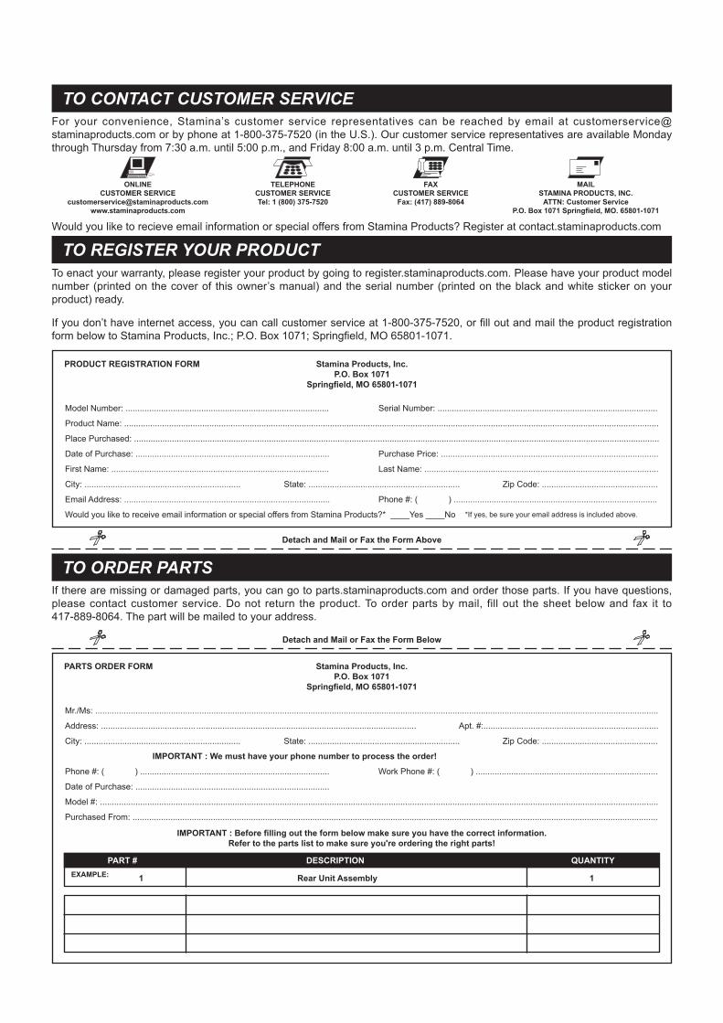
If there are missing or damaged parts, you can go to parts.staminaproducts.com and order those parts. If you have questions, please contact customer service. Do not return the product. To order parts by mail, fill out the sheet below and fax it to 417-889-8064. The part will be mailed to your address.
Mr./Ms: ..............................................................................................................................................................................................................................................
Address: ........................................ ............................................................................................. Apt. #:..........................................................................
City: .................................................................. State: ................................................................ Zip Code: .................................................
IMPORTANT : We must have your phone number to process the order!
Phone #: ( ) ................................................................................ Work Phone #: ( ) .............................................................................
Date of Purchase: ..................................................................................
Model #: ............................................................................................................................................................................................................................................
Purchased From: ..............................................................................................................................................................................................................................
IMPORTANT : Before filling out the form below make sure you have the correct information.Refer to the parts list to make sure you're ordering the right parts!
Stamina Products, Inc.P.O. Box 1071
Springfield, MO 65801-1071
Detach and Mail or Fax the Form Above
TO REGISTER YOUR PRODUCT
TO CONTACT CUSTOMER SERVICE
TO ORDER PARTS
TO CONTACT CUSTOMER SERVICEFor your convenience, Stamina’s customer service representatives can be reached by email at customerservice@ staminaproducts.com or by phone at 1-800-375-7520 (in the U.S.). Our customer service representatives are available Monday through Thursday from 7:30 a.m. until 5:00 p.m., and Friday 8:00 a.m. until 3 p.m. Central Time.
TO REGISTER YOUR PRODUCTWould you like to recieve email information or special offers from Stamina Products? Register at contact.staminaproducts.com
TELEPHONECUSTOMER SERVICETel: 1 (800) 375-7520
FAXCUSTOMER SERVICE
Fax: (417) 889-8064
MAILSTAMINA PRODUCTS, INC.
ATTN: Customer ServiceP.O. Box 1071 Springfield, MO. 65801-1071
ONLINECUSTOMER SERVICE
To enact your warranty, please register your product by going to register.staminaproducts.com. Please have your product model number (printed on the cover of this owner’s manual) and the serial number (printed on the black and white sticker on your product) ready.
If you don’t have internet access, you can call customer service at 1-800-375-7520, or fill out and mail the product registration form below to Stamina Products, Inc.; P.O. Box 1071; Springfield, MO 65801-1071.
PRODUCT REGISTRATION FORM
TO ORDER PARTS
Detach and Mail or Fax the Form Below
PARTS ORDER FORM
PART # DESCRIPTION QUANTITY
1 Rear Unit Assembly 1EXAMPLE:


![[XLS] · Web view91" X 58" ELLIPTICAL PIPE 02582 91" X 58" ELLIPTICAL CONC. PIPE 02630 98" X 63" ELLIPTICAL PIPE 02632 98" X 63" ELLIPTICAL CONC. PIPE 02680 106" X 68" ELLIPTICAL](https://img.pdfslide.net/doc/110x75/5ae3d8767f8b9a5d648e7b83/xls-view91-x-58-elliptical-pipe-02582-91-x-58-elliptical-conc-pipe-02630-98-x.jpg)