Embed Size (px)
Citation preview

1
Oxygas 500User Handbook
OXYGAS 500 USER HANDBOOK
2
Issue 2
06/06/13
Part Number: 42621
GMI welcomes comments on all our publications. Yourcomments can be of great value in helping us toimprove our customer publications. Please send anycomments that you have to our Customer SupportDepartment at GMI.

i
COPYRIGHT
This User Handbook is copyright of Gas Measurement Instruments Ltd (GMI)and the information contained within, is for use only with the Oxygas 500instrument. Reproduction, in whole or in part, including utilisation in machinescapable of reproduction or retrieval without written permission of GasMeasurement Instruments Ltd is prohibited. Reverse engineering is notpermitted.
LIABILITY
Every care has been taken in the preparation of this document, but GMI Ltddo not accept any responsibility for errors or omissions and theirconsequences. Information in this document is subject to change withoutnotice. This document does not constitute a specification or basis for acontract. Your statutory rights under law are not affected.
MODIFICATION NOTICES
GMI aim to notify customers of relevant changes in the product operationand maintain this manual up to date. In view of the policy of continuous productimprovement there may be operational differences between the latest productand this manual.
This Handbook is an important part of the Oxygas 500 product. Please notethe following points:
• It should be kept with the instrument for the life of the product.
• Amendments should be attached.
• This Handbook should be passed on to any subsequent owner/user ofthe instrument.
• Although every care is taken in the preparation of this Handbook itdoes not constitute a specification for the instrument.
SOFTWARE
Software supplied on EPROM or similar device for use in a particular product,may only be used in that product and may not be copied without the writtenpermission of Gas Measurement Instruments Ltd. Reproduction ordisassembly of such embodied programmes or algorithms is prohibited.Ownership of such software is not transferable and GMI Ltd does not warrantthat the operation of the software will be error free or that the software willmeet the customer’s requirements.
DISPOSAL ADVICE
When no longer in use, dispose of the instrument carefully and with respectfor the environment. GMI will dispose of the instrument without charge ifreturned to the factory.

OXYGAS 500 USER HANDBOOK
ii
SAFETY
• The instrument must be regularly serviced and calibrated by fullytrained personnel in a safe area.
• Batteries: Alkaline batteries or *Rechargeable battery pack must beexchanged (*and recharged) in a safe area and fitted correctlybefore use. Never use damaged batteries or expose to extreme heat.See Section 4 : OPERATOR MAINTENANCE.
• Only GMI replacement parts should be used.• If the instrument detects gas, follow your own organisation’s
procedures and operational guidelines.• The combustion chamber is a flameproof assembly and must not be
opened in the presence of a flammable atmosphere.• Gas can be dangerous and care should always be taken in its use.• Oxygas 500 instruments are certified as EEx iad IIC T4
(-20oC< Tamb < 50oC). BAS01ATEX2292 II 2 G.
UL Class 1 Groups A, B, C and D.• This equipment is designed and manufactured to protect against
other hazards as defined in paragraph 1.2.7 of Annex II of the ATEXDirective 94/9/EC
Any right of claim relating to product liability or consequential damage to anythird party against GMI is removed if the warnings are not observed.
AREAS OF USE
Exposure to certain chemicals can result in a loss of sensitivity of theflammable sensor. Where such environments are known or suspected it isrecommended that more frequent response checks are carried out. Thechemical compounds that can cause loss of sensitivity include Silicones,Lead, Halogens and Sulphur. Do not use instrument in potentiallyhazardous atmospheres containing greater than 21% Oxygen. Theenclosure material is polypropylene and must not be exposed toenvironments which are liable to result in mechanical or thermaldegradation or to damage caused by contact with aggressive substances.Additional protection may be required in environments where theinstrument enclosure is liable to damage.
STORAGE, HANDLING AND TRANSIT
The batteries in the rechargeable pack contain considerable energy and careshould be taken in their handling and disposal. Battery packs should beremoved if the instrument is stored for longer than 3 months. The instrumentis designed to handle harsh environments. The sensing elements are sealedto IP54 and the rest of the instrument to IP64. If not subject to misuse ormalicious damage, the instrument will provide many years of reliable service.The instrument contains electrochemical sensors with a life of 2 years. Underconditions of prolonged storage the sensors should be removed. The sensorcontains potentially corrosive liquid and care should be taken when handlingor disposing of the sensor, particularly when a leak is suspected.

iii
DECLARATION OF CONFORMITY
Refer to currentDeclaration of Conformitydocument Part No. 42907
(supplied with product)

OXYGAS 500 USER HANDBOOK
iv

v
REVISION RECORD
Date Issue Description OfChange
25/05/04 1 New Handbook
06/06/13 2 Revised to include effectof CN 6257.

OXYGAS 500 USER HANDBOOK
vi

vii
CONTENTS
COPYRIGHT ................................................................... i
LIABILITY ....................................................................... i
MODIFICATION NOTICES ................................................ i
SOFTWARE ................................................................... i
DISPOSAL ADVICE ........................................................ i
SAFETY ......................................................................... ii
AREAS OF USE ............................................................. ii
STORAGE, HANDLING AND TRANSIT .......................... ii
DECLARATION OF CONFORMITY................. iii
REVISION RECORD ....................................... v
INTRODUCTION ............................................. 1Overview ...................................................................... 2
Combustible Gas Indicator - Leak Detection ............. 2
Purging ....................................................................... 4
GENERAL INFORMATION ........................... 13Ranges of Operation .................................................. 13

OXYGAS 500 USER HANDBOOK
viii
LEL, 0 to 100% ......................................................... 13
Volume Gas, 0 to 100 % .......................................... 14
Oxygen, 0 – 25% ..................................................... 14
Construction ............................................................... 15
Batteries ...................................................................... 15Disposable Alkaline (LR20) Dry Cell Batteries ......... 15
Rechargeable Battery Pack ..................................... 16
Filters .......................................................................... 16
Liquid Crystal Display (LCD) ...................................... 17
Before Use Checks .................................................... 17
OPERATING INSTRUCTIONS ...................... 19Modes of Operation .................................................... 19
Switching On ........................................................... 20
Calibration Date Features ........................................ 21
Switching Off the Instrument Pump ......................... 21
Switching On in Purge Mode ................................... 22
Switching Off ........................................................... 22
Changing Range ....................................................... 23
Summary of Button Operation ................................. 23
Operator Messages / Fault Flags ............................... 24
OPERATOR MAINTENANCE ....................... 27Rechargeable Battery Pack ........................................ 27
Standard Charger ..................................................... 27

ix
CONTENTS
Flatbed Charger ....................................................... 28
Smart Charger .......................................................... 28
Replacing the Battery Pack ...................................... 29
Recharging the Battery Pack ................................... 30
Replacing Alkaline (LR20) Dry Cell Batteries ............. 30
Filter Replacement ...................................................... 32
CALIBRATION .............................................. 35Calibration Validity ....................................................... 36
ACCESSORIES ........................................... 37
ADDITIONAL INFORMATION ........................ 41Training ....................................................................... 41
World Wide Web ......................................................... 41
TYPICAL OPERATING PARAMETERS ....... A-1Size ........................................................................ A-2
Weight .................................................................... A-2
Operating Temperature .......................................... A-2
Humidity .................................................................. A-2
Construction ........................................................... A-2
Display .................................................................... A-2
Sampling System .................................................... A-2

OXYGAS 500 USER HANDBOOK
x
Response Time (O2) .............................................. A-2
Power Source ........................................................ A-3
FIELD CALIBRATION .................................. B-1Selectable Ranges in FCM ........................................ B-3
Entering FCM ............................................................. B-3
Zeroing the Instrument ............................................. B-4
Field Calibration Procedure ....................................... B-5
Quitting FCM .............................................................. B-9Quit And Save Changes ........................................ B-9
Quit Without Saving Changes ................................ B-9
OPERATING INSTRUCTIONS ..................... C-1English ..................................................................... C-2
Deutsch (German) .................................................. C-6
L'italiano (Italian) ................................................... C-10
Svensk (Swedish) ................................................ C-14
Dansk (Danish) ...................................................... C-18
Nederlands (Dutch) ............................................. C-22
Greek ..................................................................... C-26
INDEX ............................................................. I

1
INTRODUCTION
The Oxygas 500 is a two button instrument designed tomeasure Lower Explosive Level, Volume flammable gasand Oxygen for (CGI) leak detection and purge operations.The instrument is designed to the latest standards and iscertified for use in Hazardous Areas.
Figure 1.1 Oxygas 500 Instrument
The Oxygas 500 contains the following ranges:
• LEL, 0 to 100%
• Volume gas, 0 to 100%
• Oxygen, 0 to 25%
1
OXYGAS 500 USER HANDBOOK
2
Overview
This chapter provides a brief overview of the principles ofoperation of the instrument in its two modes of operation.
1) Combustible Gas Indicator (CGI) - Leak Detection
2) Purging
This is not intended as operating instruction in theapplication of finding leaks, monitoring atmospheres orpractical purging operations. In all cases, you should followyour company and application specific training.
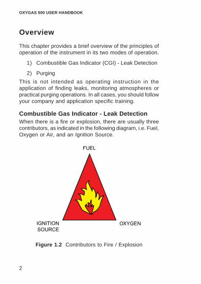
Combustible Gas Indicator - Leak DetectionWhen there is a fire or explosion, there are usually threecontributors, as indicated in the following diagram, i.e. Fuel,Oxygen or Air, and an Ignition Source.
Figure 1.2 Contributors to Fire / Explosion

3
In some applications, all three sources are available,e.g. a boiler burner.
In other applications, where gas may be liable to escapeor be present, ignition sources are controlled,e.g. hazardous or zoned areas.
In applications, such as purging, the Air or Oxygen sourceis controlled or excluded.
In normal operation, where air is not excluded apart fromdisplacement by the fuel itself, fuel and air can mix causingpotentially explosive mixtures.
If insufficient fuel is present, e.g. the mixture is too “lean”to cause ignition, then the atmosphere is “safe”.
The minimum amount of fuel in air that can cause anexplosion is called the Lower Explosive or Flammable Limit- LEL / LFL. If the mixture has too much fuel, and henceinsufficient air, then again combustion cannot occur. Themaximum fuel in air ratio, where combustion can occur, iscalled the Upper Explosive or Flammable Limit - UEL / UFL.
These figures assume normal atmospheres - gas in air -21% Oxygen in 79% Nitrogen. If either the 02 or the N2ratio varies significantly, then different conditions apply tothe flammable limits and the instrument application.
The normal measurement for gas in air atmospheres is% LEL.
This measurement is not used in inert atmospheres wherethe % Gas or % Oxygen measurement must be used.
INTRODUCTION

OXYGAS 500 USER HANDBOOK
4
Figure 1.3 Flammability
The Oxygas 500 uses a catalytic sensor to measure LEL,which requires air to be present, and a thermal conductivitysensor to measure the % Volume range.
PurgingThe opening of a pipeline or vessel causes a mixing offlammable products, such as gas with air, creatingpotentially flammable mixtures.
It may not be possible to ensure that all sources of ignitionare removed, hence there is a need to avoid the formationof flammable mixtures.
Two types of purging are generally used:
• Direct Purging - Displacement of fuel by air, or viceversa.
• Indirect Purging - Displacement of fuel by inert gasfollowed by displacement by air, or vIce versa.
Indirect purging is the most common since it avoidsflammable mixtures being created.
5
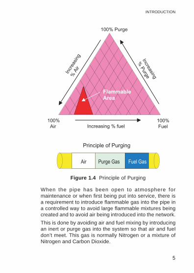
Figure 1.4 Principle of Purging
When the pipe has been open to atmosphere formaintenance or when first being put into service, there isa requirement to introduce flammable gas into the pipe ina controlled way to avoid large flammable mixtures beingcreated and to avoid air being introduced into the network.
This is done by avoiding air and fuel mixing by introducingan inert or purge gas into the system so that air and fueldon’t meet. This gas is normally Nitrogen or a mixture ofNitrogen and Carbon Dioxide.
INTRODUCTION

OXYGAS 500 USER HANDBOOK
6
The following diagram illustrates a typical direct purgingoperation and is not intended to demonstrate the purgetechnique, but illustrate the effect on the instrumentreading.
Figure 1.5 Direct Purging - Commissioning
Commissioning
In the direct purge mode for commissioning, the pipe wouldcontain air and the pipe would be purged with NaturalGas. The Oxygas is zeroed in air and would be switchedon in the purge mode. In commissioning the pipe wouldtypically be purged to 95% Natural Gas. This would be anormal operation, however, in instruments calibrated inMethane you may only be able to attain 85-90% reading,depending upon the composition of the gas and theaccuracy of calibration. The Natural Gas may only contain90% or less of Methane, hence the calibration gas andthe measured gas should be as close together as possiblein composition for purging or an allowance made for thedifference.

7
De-commissioning
In purging down to air the typical figure would be 2%Methane or around 40% LEL to end the purge.
In the Purge mode only the % Gas and the 02 ranges areavailable and normally the % Vol range can be used. Areading can be taken from the 02 range for confirmationbut care should be taken that the pressure applied to thecell is the same or similar to the zero point, ie atmosphericpressure. The pipe is being pressurised from atmospherichence by inference the pressure will change. The 02 cellcan be pressure transient sensitive, so care should betaken to ensure that the pressure is maintained the sameby means of suitable valves or flow orifices and timeallowed for the transient effect to be minimised before areading is taken.
Direct Purging
Although it is normal to use the Purge mode of the Oxygasfor purging, in direct purging where there is no inertatmosphere in the pipe the instrument will operate in theMeasure mode.
Figure 1.6 Direct Purging - De-commissioning
INTRODUCTION

OXYGAS 500 USER HANDBOOK
8
When commissioning, the instrument will start in the LELrange and autorange up automatically to % Gas when theLEL reaches around 110% or the %Gas is greater thanabout 5.5%. Thus above these values of gas in air theinstrument will be in the %Gas range and the readingincrease up to the final purge reading of >95% gas (85 -95% depending on calibration).
In direct purging to air the instrument in the measure modewill start off in % Gas and reduce the reading in the gasrange until it autoranges back to LEL at around 4.5% CH4in air or 99% LEL.
In the measure mode the LEL and % Vol ranges haveautotracking which forces the LEL and % Gas signals tobe the same.
In the Purge mode the instrument will only have % O2 and% Gas ranges and autotracking is disabled.
With 2% CH4 or 40% LEL the Oxygen content of thesample is only reduced by around 0.4% O2 which may bedifficult to measure accurately.
THE MEASURE MODE SHOULD NOT BE USED FORINDIRECT PURGING.

9
Indirect Purging
The following diagram shows a typical indirect purgingoperation using a Nitrogen cylinder.
Figure 1.7 Indirect Purging - De-commissioning
In this situation Nitrogen or an inert gas is used to purgethe vessel of flammable gas; the above illustration doesnot fully describe purging, only its influence on theinstrument.
For indirect operations, the instrument must be used inthe purge mode.
In decommissioning the pipe, the end point is the % ofGas left in the pipe when it has mainly been displaced byNitrogen. A typical figure for this would be 7.5 - 8%CH4 togive a mixture that when mixed with air would not form anexplosive mixture. Since there is no air in the pipe, Oxygenmeasurement cannot be used apart from as a safetycheck.
Nitrogen has a different thermal conductivity to air andhence the reading for 100% Nitrogen is different than for100% Air (20% O2 / 80% N2).
INTRODUCTION

OXYGAS 500 USER HANDBOOK
10
Since 100% air is used to set zero at switch-on, it is thezero that is affected by the difference between air andNitrogen.
There is a typical difference in reading between thesetwo conditions of around 5% on the % Volume scalewhen calibrated in Methane on an Oxygas.
100%Nitrogen gives a negative reading of around -5%when compared with an air zero and obviously the 20%O2 reading drops to O% in 100% N2.
To enable the influence of the Nitrogen to be seen andcompensated for in this condition, when the Oxygas isplaced in the PURGE mode negative readings are enabledon the %Gas scale. The instrument will read approximately-5% when in a 100% N2 atmosphere and the results willbe influenced by the % of N2 in the sample as the readingis reduced.
Block
Figure 1.8 Indirect Purging - Commissioning(Air to Inert)

11
GENERAL INFORMATIONINTRODUCTION
At an actual 5% CH4 in Nitrogen the influence of theNitrogen on the % Gas reading is around 95% of -5% gas= - 4.75%, hence the actual meter reading will be around+0.25%.
At 7.5% CH4 the reading will be influenced by the zeroshifting by 92.5% of -5 = +3%.
At an actual reading of 7.5% the mixture will be higher inconcentration by around 2.5 - 3% gas.
These numbers still fall within the 30% safety factornormally used.
GMI recommend that you take the time to study yourinstrument and, where practical and with advice fromyour company’s Purchasing / Management departments,highlight your particular instrument configuration.
The main features of the instrument are:
• Rugged carbon loaded polypropylene case, sealedto IP54 rating and suitable for outdoor use.
• Two-button operation allowing the user access toall features.
• LCD with backlighting which displays the currentgas readings (in both digital and analogue forms)together with operational and status information.
• Directly interfaces with the GMI Auto Test Calibra-tion Units.

OXYGAS 500 USER HANDBOOK
12

13
GENERAL INFORMATION
Ranges of Operation
LEL, 0 to 100%The LEL range indicates the explosivity of the flammablegas in the sample. This is displayed as a percentage ofthe lower explosive limit (LEL) of the gas. For methane100% LEL corresponds to 5% Volume methane in Air.
The instrument range is displayed in the top right cornerof the display as % LEL. From 0 to 10% LEL the digitaldisplay resolves to 0.1% LEL. From 10 to 100% LEL thedigital display resolves to 1% LEL. The analogue bar graphfollows in 4% steps. An example of the LEL display isshown in Figure 2.1. Autoranging will automatically switchthe range to Volume Gas when 100% LEL is reached.
The detection principle for this range is a catalyticreaction.
Figure 2.1 LEL Range
2

OXYGAS 500 USER HANDBOOK
14
Volume Gas, 0 to 100 %This range displays the total volume of a specificflammable gas with respect to air. The calibration gas isshown on the service label and for the purpose of thishandbook is assumed to be methane. Instrumentscalibrated for methane in air should only be used formeasuring such mixtures. To change the calibration gas,e.g. from methane to propane, the instrument must berecalibrated by suitably trained personnel.
On the Volume Gas range the instrument range isdisplayed in the top right corner of the LCD as GAS.The digital display resolves the signal to 1% GAS withthe analogue bar graph following in steps of 4%. Figure2.2 shows the Volume Gas display. The detectionprinciple for the Volume Gas range is thermalconductivity.
Figure 2.2 Volume Gas Range
Oxygen, 0 – 25%This range displays the percentage Oxygen content ofthe sample. The instrument range is displayed in thetop right corner of the display as % O2. From 0 to 21%O2 the digital display resolves to 0.1% O2. From 21 to25% O2 the digital display resolves to 1% O2. Theanalogue bar graph follows in 4% steps.

15
The gas level is determined using an electrochemical cell,which like toxic sensors is sensitive to pressuretransients. The oxygen cell has an expected life of twoyears.
ConstructionThe instrument is housed in a tough, impact resistant,moulded case made of carbon loaded polypropylene.
The top panel is protected by a stainless steel top platecovering a toughened glass LCD cover.
The battery pack is sealed and attached to the maininstrument body by means of 2 stainless steel hexagonalscrews.
The instrument is sealed against dust and water to IP54standard. The sensors are protected from dust and waterby membrane and cotton filters.
Batteries
Disposable Alkaline (LR20) Dry Cell BatteriesAlkaline batteries provide approximately 15 hoursoperational life at ambient temperature of 20oC (68oF).When the batteries are low or exhausted it is necessary tofit 4 new batteries. Do not mix old and new batteries.
An indication of the battery condition is displayed afterpower on and during warm-up, with status shown as eitherOK or LO. If LO condition is displayed, a maximum batteryoperational life of 120 minutes remains. During operationthe ‘BAT’ flag is displayed when approximately 60 minutesof operating time remains at normal temperature. Theinstrument may continue to be used until it switches offautomatically.
GENERAL INFORMATION

OXYGAS 500 USER HANDBOOK
16
Rechargeable Battery PackThe GMI rechargeable battery pack providesapproximately nine hours operational life, from fullycharged, at ambient temperature of 20oC (68oF). Anindication of the battery condition is displayed after poweron and during warm-up, with status shown as either OKor LO. If LO condition is displayed, a maximum batteryoperational life of 90 minutes remains. During operationthe ‘BAT’ flag is displayed when approximately 30 minutesoperating time is left at normal temperatures. Theinstrument will then turn off.
There are three GMI Battery Chargers: a Standard Charger,a Flatbed Charger and a Smart Charger. The SmartCharger has both slow and fast charge options as well asa serial link for communications with the instrument. SeeRechargeable Battery Pack in Section 4 OPERATORMAINTENANCE.
FiltersA number of different filter types are available from GMI.The minimum requirement is a cotton particulate filter anda hydrophobic filter which are incorporated in the probehandle assembly supplied with the instrument. Filters mustbe checked at frequent intervals and where appropriatechanged to ensure a clean sample path. If water is drawninto the instrument any filter which has been contaminatedmust be cleaned or replaced. See Filter Replacement inSection 4 OPERATOR MAINTENANCE.

17
Liquid Crystal Display (LCD)The LCD shows the current gas readings in both analogueand digital form together with operational and statusinformation. The display is protected by a toughened glasscover. Backlighting is provided to enable the display to beseen under low ambient light conditions.
Before Use ChecksThe following checks should be carried out before usingthe instrument on site:
• The instrument is clean and in good condition.
• The batteries have sufficient power left in themfor the intended use of the instrument.
• The filters are clean and in good condition.
• The sample line and any accessories are in goodcondition and leak free.
• All gas ranges are operational and zeroed cor-rectly.
• The calibration is still valid.
GENERAL INFORMATION

OXYGAS 500 USER HANDBOOK
18

19
OPERATING INSTRUCTIONS
Modes of OperationThe instrument has two modes of operation which areaccessed by switching the instrument ON with either Button
One or Button Two . See Figure 3.1 below.
Figure 3.1 Instrument Front Plate
Mode 1 (CGI): Switching ON with Button One
provides three gas ranges
a) LEL autoranging to Volume Gas, and
b) Oxygen Range 0-25%.
3

OXYGAS 500 USER HANDBOOK
20
Mode 2 (Purge): Switching ON with Button Two
provides access to only 0-100% Vol Gas and 0-25%Oxygen for purge applications.
Switching On
Press and hold Button One to turn the instrument on.
This initiates the instruments warm up cycle and switcheson the pump. Figure 3.2 displays the warm up cycle forthe Oxygas 500.
%VSAMPLE STORE
ZEROFAULT
CHECKBAT
10000PPM80006000400020000 �
BAT
V
Figure 3.2 Warm Up
Note: Battery status is displayedas either OK or LO at start-up.

21
Calibration Date FeaturesAt the end of warm-up and before the Oxygas 500instrument is ready for measuring, the instrument willindicate on the display when the next calibration is due.This will be displayed as month and year, as shown inFigure 3.3:
(Alternate flash)Calibration DueFebruary 2005
Figure 3.3 Calibration Date
The re-calibration interval pre-set for all Oxygas 500instruments is twelve (12) months.
This period can be altered as an option, however, youshould ensure that the instrument is always within itscalibration period prior to use.
An option which ensures that an ‘out of calibrationinstrument’ is not used, is the automatic switch-off whenoverdue.
Switching Off the Instrument Pump
A single press of Button One , when the pump is
running, turns the pump off and stops sampling. Pressingbutton one again turns the pump back on.
OPERATION

OXYGAS 500 USER HANDBOOK
22
Switching On in Purge ModeTo switch on in Purge mode, press and hold Button Two
. The Oxygas 500 will initiate the warm-up sequence
as explained previously. This mode uses the Volume Gasand Oxygen ranges only. When in purge mode, the PURGEflag is activated on the display, as shown in Figure 3.4.
(Alternate flash)
Figure 3.4 Purge Mode
Switching Off
A double press of Button One turns the instrument
off immediately.
The instrument switches off automatically after 30minutes. ‘OFF’ is shown in the top right hand corner of thedisplay. Pressing any button cancels this automatic switch-off. The instrument will then allow another 30 minutes ofuse.
This 30 minute period is set as a default.
The switch off time may be altered to any time between 1and 1000 minutes

23
Changing Range
Each single press of Button Two changes the gas
range selected. The display cycles through the availableranges as follows:
LEL/Vol.Gas – Oxygen – LEL/Vol.Gas (in CGI mode)
Volume Gas – Oxygen – Volume Gas (in Purge mode)
Note: The instrument, by default, auto-ranges betweenLEL and Volume Gas.
Summary of Button Operation
egnaRtxeN
Mode Single Press Press andHold
DoublePress
Button 1
Button 2 _
Toggles PumpOn / Off
(during operation)
LEL/VOL - O - LEL/VOL (CGI)VOL - O - VOL (Purge)2
2
SwitchesInstrumentON (CGI)
SwitchesInstrumentON (Purge)
SwitchesInstrument
OFF
OPERATION

OXYGAS 500 USER HANDBOOK
24
Operator Messages / Fault FlagsVarious messages can appear on the LCD screen toindicate instrument status.
‘SAMPLE’
This indicates that the pump is running and the instrumentis sampling.
‘OFF’
This indicates that the instrument is about to switch off.This command can be cancelled by a single press of anybutton.
‘SAMPLE FAULT’
This indicates a problem with the instrument’s flow due tothe sample path being blocked, water ingress, a blockedfilter or pump failure.
In Measure mode, the pump stops automatically. Thesample line, filters etc. should be checked for water
ingress or blockage and Button One should then be
pressed to restart the pump.
‘CHECK ZERO’
This indicates that there may have been a zero shift dueto the presence of gas. Switch off the instrument and switchon again in fresh air.
‘ZERO FAULT’
This indicates that the zero is outwith its calibration limits.Switch the instrument off and then on again in fresh air. Ifthe fault does not clear, return the instrument for servicing.

25
OPERATION
‘BAT’
This indicates that the batteries will soon requirereplacement. At this point there will be approximately 60minutes operation left in a set of alkaline batteries, althoughthis figure will vary depending on battery manufacturer,temperature conditions, usage etc. With rechargeablebatteries the ‘BAT’ flag indicates approximately 30 minutesoperation left.
As the battery power continues to fall, the LCD flashes a‘BAT FAULT’ message. Subsequently the LCD displays‘OFF’ and the instrument automatically switches off. Thebatteries should be replaced immediately.
‘BAT FAULT’
This indicates that the batteries require replacing.
‘1’This message which can also appear after power on,indicates that a calibration data error has been detected.The instrument should be returned for servicing.

OXYGAS 500 USER HANDBOOK
26
27
OPERATOR MAINTENANCE
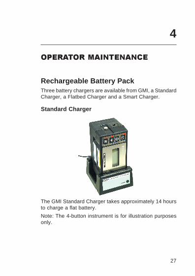
Rechargeable Battery PackThree battery chargers are available from GMI, a StandardCharger, a Flatbed Charger and a Smart Charger.
Standard Charger
The GMI Standard Charger takes approximately 14 hoursto charge a flat battery.
Note: The 4-button instrument is for illustration purposesonly.
4

OXYGAS 500 USER HANDBOOK
28
Flatbed Charger
The GMI Flatbed Charger allows the Oxygas 500 batterypack to be charged in NORMAL mode, which takesapproximately 14 hours to charge a flat battery. The ModeSelect Switch can then be set to STAND-BY, where a tricklecharge will maintain the battery in a fully charged state ofreadiness.
Note: The 4-button instrument is for illustration purposesonly.
Smart Charger
29
OPERATOR MAINTENANCE
The GMI Smart Charger provides both fast and standardcharging facilities and can charge an instrument and sparebattery pack simultaneously. Using the standard chargingoption, a battery pack can be recharged in 12 hours froma fully discharged state. Using the fast charge option abattery pack can be 90% recharged in approximately 60minutes and fully recharged in 120 minutes. To ensureoptimum life length, the rechargeable pack should be fullydischarged and charged on a regular basis of, at least,every three months. The Smart Charger has the option ofswitching to discharge and fast charge cycle to providethis facility.
Note: The 4-button instrument is for illustration purposesonly.
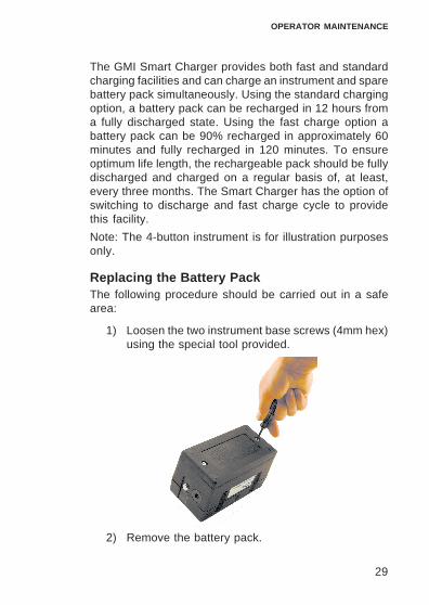
Replacing the Battery PackThe following procedure should be carried out in a safearea:
1) Loosen the two instrument base screws (4mm hex)using the special tool provided.
2) Remove the battery pack.

OXYGAS 500 USER HANDBOOK
30
3) Insert new battery pack.
4) Fasten base screws.
5) Check that instrument switches on and works tospecification.
Recharging the Battery PackThe battery pack should be recharged in the followingsituations:
The BAT or BAT FAULT message is displayed.
The instrument will not switch on.
The pump will not switch on.
It is recommended that the battery pack is fully dischargedon a regular basis (once every three months). This can bedone by running the instrument continuously or using thebattery conditioning facility on the Smart Charger. Thebatteries can be charged on the instrument but theinstrument itself should be switched off. Regular completedischarge will keep the battery pack in good condition.
Replacing Alkaline (LR20) Dry CellBatteriesAll four batteries should be replaced at any one time andin a safe area. GMI only recommend the use of Energiseror Duracell cells.
1) Loosen the two instrument base screws (4mm hex)using the special tool provided.

31
OPERATOR MAINTENANCE
2) Remove battery cover.
3) Remove the old batteries.
4) Check battery compartment for damage to springcontacts or corrosion on springs.
Caution: Under no circumstances should rechargeablebatteries be fitted in place of Alkaline batteries.
5) Insert four new batteries observing correct polarityindication in battery compartment base.
6) Replace battery cover and fasten base screws.
7) Check that the instrument switches on and worksto specification.

OXYGAS 500 USER HANDBOOK
32
Filter ReplacementHydrophobic and cotton particulate filters in the probehandle minimise the danger of water and dust ingress.
Caution: The instrument should never be switched onwithout suitable filters installed.
If a blockage occurs the ‘SAMPLE FAULT’ indicator isdisplayed. Check the sample line and probe handle for
blockage. Press Button One to clear the ‘SAMPLE
FAULT’ message. Replace the filter(s) if the message doesnot clear.
To replace the filter(s), proceed as follows:
1) Unscrew the probe handle assembly.
Hydrophobic Filter
Cotton Particulate Filter
Probe Handle Assembly
Figure 4.1 Filter Assembly

33
OPERATOR MAINTENANCE
2) Remove the cotton particulate filter and discard.
3) Remove the hydrophobic filter.
4) Clean the probe handle to make sure that it is freefrom dirt and water.
5) Fit a new cotton particulate filter.
6) Fit the hydrophobic filter. The yellow label on thefilter fits against the yellow label on the probehandle.
7) Reassemble the probe handle assembly.

OXYGAS 500 USER HANDBOOK
34

35
CALIBRATION
The instrument has been calibrated for a particularflammable gas mixture. Where any doubt exists theinstrument should be returned to GMI or an authoriseddistributor for calibration.
Four methods of calibration are possible:
• Field Calibration. See APPENDIX B, FIELD CALI-BRATION for further details.
• Manual Calibration. The instrument can be linkedto a PC running GMI Manual Calibration software.
• Automatic Calibration. The GMI Auto Test Calibra-tion System allows calibration without manuallychanging gas cylinders. The system links to a PCrunning GMI Workshop software.
• The GMI Instrument Management System (IMS)provides all the facilities of the Auto Test Calibra-tion System with the added feature of instrumentdatabase management.
Note: The calibration systems above (hardware andsoftware) are manufactured by GMI. For moredetails contact GMI or an authorised distributor.
5

OXYGAS 500 USER HANDBOOK
36
Calibration ValidityCalibration validity is the responsibility of the user. Undernormal operating conditions a 12 month period can beexpected. This is no guarantee, however, as the preciseapplication of the product is unknown to GMI. Individualcodes of practice may dictate shorter periods.
Regular checking establishes a pattern of reliability andenables the calibration check period to be modified in linewith operational experience. The higher the risk, the morefrequently calibration should be checked.

37
ACCESSORIES
Accessories Supplied with the Oxygas 500 Instrument
Part Number 42501X / 42501XR
Part Number Description
42247 Carrying Case12370/2 Shoulder Harness12451 4mm Hex. Driver12712 Clear Sample Line x 1.5 metres.
(4ft.10ins.) approx.12480 Plastic Probe - Solid End
35cm. (1ft.2ins.) approx.12481 Probe Handle c/w Filters10077 Cotton Particulate Filters (Box of 10) x 212688 Sample Line Adaptor42621 User Handbook
Additional Accessories Available
Part Number Description
13184 Standard Charger / 240V Power Supply(UK PLug)
13317 Standard Charger / 220V Power Supply(Euro Plug)
13322 Standard Charger / 110V Power Supply(USA Plug)
6

OXYGAS 500 USER HANDBOOK
38
12888 Standard Charger / 220V Power Supply(Australian Plug)
13179 Standard Charger w/o Power Supply42121 Flatbed Charger / 240V Power Supply
(UK PLug)42122 Flatbed Charger / 220V Power Supply
(Euro Plug)42123 Flatbed Charger / 110V Power Supply
(USA Plug)12889 Flatbed Charger / 220V Power Supply
(Australian Plug)42124 Flatbed Charger w/o Power Supply13180 240V Power Supply (UK Plug)13320 220V Power Supply (Euro Plug)13321 110V Power Supply (USA Plug)12241 220V Power Supply (Australian Plug)13100 Smart Charger with Datalogging Software
c/w 240V Power Supply (UK Plug)13440 Smart Charger with Datalogging Software
c/w 220V Power Supply (Euro Plug)13340 Smart Charger with Datalogging Software
c/w 110V Power Supply (USA Plug)12890 Smart Charger with Datalogging Software
c/w 220V Power Supply (Australian Plug)42114 Spare Rechargeable Battery Pack13703 Manual Calibration for Windows Software12552 Communications Link Adaptor12358 Hydrophobic Filter
(use with 12481)12229 Stainless Steel Probe - Closed End
80cm. (2ft.6ins.) approx.12393 Plastic Probe - Solid End
80cm. (2ft.6ins.) approx.

39
12394 Flexible Probe - Open End35cm. (1ft.2ins.) approx.
13427 Plastic Probe - Open End35cm. (1ft.2ins.) approx.
13413 Stainless Steel Probe - Open End35cm. (1ft.2ins.) approx.
12895 Barbed Probe - Solid End69cm. (2ft.3ins.) approx.
12894 Barbed Probe - Open End69cm. (2ft.3ins.) approx.
13561 Probe Handle13562 Probe Handle Adaptor
(use with 13563 or 13565)13563 Bellows Cup Probe13565 Swan Neck Probe13655 Probe Shroud c/w Skids (use with 13565)12365 In-Line Hydrophobic Filter Holder42141 Gasurveyor 500 Standard Accessory
Pack.Consisting of: Gasurveyor 500 CarryingCase ; Standard Probe ; Probe HandleAssembly ; Sample Line Adaptor ;2 Packs Cotton Filters.
42151 Gasurveyor 500 Gas Industry SurveyAccessory Pack.
Consisting of: Gas Industry SurveyCarrying Case (Large) ; Probe HandleAssembly ; Probe Handle Adaptor ;Bellows Probe.Note: Large carrying case has spacefor special probes, e.g. Swan Neck
Note: For other sampling probes and accessories, and forcalibration gases, contact GMI Ltd.
ACCESSORIES

OXYGAS 500 USER HANDBOOK
40

41
7
ADDITIONAL INFORMATION
TrainingTraining courses are available on all our products. Contactour Marketing Department for further details:
Tel: +44 (0) 141 812 3211
Fax: +44 (0) 141 812 7820
e-mail: [email protected]
World Wide WebVisit our web site at www.gmiuk.com

OXYGAS 500 USER HANDBOOK
42

A-1
TYPICAL OPERATING PARAMETERS
TYPICAL OPERATING
PARAMETERS
Typical operating parameters are as follows:
Gas Range Resolution Zero AccuracyRange Stability
LEL 0 to 10% 0.1% +/- 0.5%10 to 100% 1% N/A 2% +/- 1% LEL
Volume 0 to 100% 1% +/- 2% 1% +/- 1% GasGas
Oxygen 0 to 21% 0.1% +/- 0.5% +/- 0.5% + 3% reading21 to 25% 1% N/A +/- 0.5% + 3% reading
Notes:
All the values above are at normal temperature and pressure.Humidity is between 0% and 95% RH (non-condensing).Pressure changes at the inlet and exhaust are minimised as they maycause transient changes in reading.
A

OXYGAS 500 USER HANDBOOK
A-2
Size180mm (7.08”) x 95mm (3.74”) x 105mm (4.13”)
Weight1.7kg (3.75lbs.) with alkaline batteries
Operating Temperature-20 oC to 50 oC (-4 oF to 122 oF)
Humidity0 – 95% RH
ConstructionMoulded polypropylene case protected to IP54
DisplayLCD containing:
Analogue display scaled 0-10, 0-100, 0-1000 or 0-10000
4 digit digital display
3 character range indication
Operational flags
Sampling SystemIntegral pump with flow fail sensor. Nominal flow rate is0.5 to 0.7 litres per minute. Typical flow fail rate is 0.1 to0.2 litres per minute.
The sample path is protected by the hydrophobic filterand automatic pump switch off.
Response Time (O2)Typical Oxygen (t90) response time is 12 seconds.
This apparatus conforms to standard EN 50104.

A-3
TYPICAL OPERATING PARAMETERS
Power Source4 ‘D’ size alkaline cells providing approximately 15 hoursruntime at 20 oC (68 oF)..
Rechargeble (NiCd) battery pack providing approximately9 hours runtime at 20 oC (68 oF).

OXYGAS 500 USER HANDBOOK
A-4
B-1
B
FIELD CALIBRATION
Field calibration allows simple calibration to be carried outin the field without the use of additional test equipment.Other calibration procedures require the use of the GMIManual Calibration software or the Workshop System.
There are fundementals, in terms of instrument calibration,that should be noted:
• The gas should be of known traceable quality andhave total analysis.
• The gas should be applied in the same manner asthe instrument is used, e.g. at a known pressurewhich is constant and around, or slightly above,normal atmospheric pressure.
• The use of demand type regulators is not recom-mended on instruments with Oxygen or Toxic cellssince these are affected by pressure pulses.
In Field Calibration Mode (FCM) the buttons perform thefunctions indicated in CAL Mode or SPAN Mode as shownin Figure B-1.

OXYGAS 500 USER HANDBOOK
B-2
ON OFFPUMP
ON OFFINST.
RANGE
PURGE
CGI
ON
Figure B-1 Button Functions
To simplify button operation when calibrating theinstrument, an overlay card, shown in Figure B-2, isavailable and can be placed over the top face of theinstrument to identify calibration button functions.Contact GMI for details.
Figure B-2 Instrument Overlay Card

B-3
Selectable Ranges in FCMWhen in FCM the following ranges are manually selectable
by pressing Button Two : LEL, Volume GAS, Oxygen.
Entering FCM
1) Switch the instrument on and allow it to completeits warm-up checks.
2) Double press Button One to initiate instrument
switch off. While OFF is displayed in the LCD andbefore the instrument actually switches off, enterthe access code.
Note: Allow at least one second between button presseswhen entering the button sequence. The default(factory set) entry code is button sequence 1,2,1,2.Alternative codes are user selectable.
When the instrument is in FCM, the “CAL” messagealternates on the display with the currently selected range.An example of the display is shown in Figure B-3.
Figure B-3 Field Calibration Display
FIELD CALIBRATION

OXYGAS 500 USER HANDBOOK
B-4
In CAL mode, the instrument buttons have the functionsshown in Figure B-4.
Single Press Double Press Press andHold
Button 1
Button 2
Figure B-4 CAL Mode Button Functions
Zeroing the Instrument
1) Enter FCM. See the previous section ENTERINGFCM.
2) Double press Button Two to zero current gas
range.
3) Single press Button Two to select the next
gas range.
4) Repeat steps 2 and 3 until all gas ranges havebeen zeroed.
5) Proceed to FIELD CALIBRATION PROCEDURE tocalibrate the instrument.

B-5
Field Calibration Procedure
1) Zero gas ranges before attempting calibration. Seeprevious section ZEROING THE INSTRUMENT fordetails.
2) Make sure that the instrument pump is running andthe gas range selected is compatible with thecalibration gas.
Note: A single press of Button One toggles the pump
Off / On.
3) Remove the cap from calibration gas cylinder. Makesure that the regulator valve is in the fully closedposition (Off) then connect the gas regulator to thegas cylinder (push down gently and tightenclockwise, hand tight). See Figure B-5 for details.
Figure B-5 Connecting Gas
FIELD CALIBRATION

OXYGAS 500 USER HANDBOOK
B-6
4) Turn the regulator valve counter clockwise to openthe valve slightly. Make sure that the gas is flowingbefore connecting the sample tubing to theinstrument, otherwise an instrument sample faultmay occur.
5) Connect tubing from regulator to instrument inletthen adjust the regulator valve to maintain aconstant flow of gas (counter clockwise to increaseflow and clockwise to decrease).. The correct flowrate is achieved when the ball in the indicator tubefloats just above its resting position.
6) Wait for the instrument gas reading to settle.
7) If the displayed reading corresponds to theconcentration of calibration gas, i.e. 50% LEL (2.5%Methane in Air), proceed to paragraph 10.
8) If the displayed reading does not correspond to theconcentration of calibration gas, i.e. 50% LEL (2.5%
Methane in Air), press and hold Button One to
enter SPAN mode.
SPAN mode is indicated by the selected range, inthis case LEL, and SPN alternating in the displayas shown in Figure B-6.
Figure B-6 SPAN Mode Display

B-7
In SPAN mode, the instrument buttons have the functionsshown in Figure B-7.
Single Press Double Press Press andHold
Button 1
Button 2
Figure B-7 SPAN Mode Button Functions
8a) In SPAN mode, a single press of Button One
will produce small incremental changes to increasedisplay reading, or a single press of Button Two
will produce small decremental changes to
decrease display reading, until the displayed gasvalue corresponds to the concentration of thecalibration gas.
8b) When required reading has been reached, press
and hold Button Two to exit SPAN mode with
calibration. The display may jump above and belowrequired reading momentarily as the instrumentperforms the calibration.
Note: If for any reason you require to exit SPAN modewithout calibration of the instrument, press and hold
Button One .
FIELD CALIBRATION

OXYGAS 500 USER HANDBOOK
B-8
9) The calibrated instrument display will now returnto CAL mode display as shown in Figure B-8.
Figure B-8 50% LEL Display
10) Make sure that correct reading is displayed beforedisconnecting the calibration gas then disconnecttubing from instrument inlet and turn regulator valveon calibration gas cylinder in a clockwise directionto turn off gas flow.
11) Make sure that the regulator valve is in the fullyclosed position (Off) then disconnect the regulatorfrom the gas cylinder (turn regulator body in acounter clockwise direction).
12) Replace the cap on the calibration gas cylinder.
13) Repeat steps 1 to 12 for each range to be calibratedotherwise quit FCM. See QUITTING FCM for furtherdetails.

B-9
FIELD CALIBRATION
Quitting FCM
Quit And Save Changes
1) Press and hold Button Two to save CAL data.
2) Double press Button One to exit FCM.
Note: When all ranges have been zeroed, calibratedcorrectly, CAL data saved and followed by CALmode exit, the new CAL DUE date will be set to 12months from now. (This can be altered to a differentfrequency, via the set-up program, e.g. 6 monthsfrom now. Contact GMI for details).
Quit Without Saving Changes
1) Double press Button One to exit FCM.
Note: When you exit the FCM without saving the new CALdata, the old calibration data and calibration dateremains in the instrument memory.

OXYGAS 500 USER HANDBOOK
B-10

C-1
C
OPERATING INSTRUCTIONS
The following multi-language instructions provide the userwith a quick guide to the operation of the . . .
Oxygas 500 instrument.
Each language and pages reference is as follows:
• English - pages C-2 to C-5
• Deutsch (German) - pages C-6 to C-9
• L'italiano (Italian) - pages C-10 to C-13
• Svensk (Swedish) - pages C-14 to C-17
• Dansk (Danish) - pages C-18 to C-21
• Nederlands (Dutch) - pages C-22 to C-25
• Greek - pages C-26 to C-29
C-2
GAS MEASUREMENT INSTRUMENTS LTD.
CHECKLIST1. Check the instrument has no obvious faults.2. Check accessories.3. Read and understand handbook before use.4. Switch ON5. Check battery levels.6. Check “ZERO” in fresh air.
SAFETY• The instrument must be regularly serviced and calibrated by
fully trained personnel in a safe area.• Batteries: Alkaline batteries or *Rechargeable battery pack
must be exchanged (*and recharged) in a safe area and fittedcorrectly before use. Never use damaged batteries or exposeto extreme heat.
• Only GMI replacement parts should be used.• If the instrument detects gas, follow your own organisation’s
procedures and operational guidelines.• The combustion chamber is a flameproof assembly and must
not be opened in the presence of a flammable atmosphere.• Oxygas 500 instruments are certified as
EEx iad IIC T4 (-20oC < Tamb < 50oC).
BAS01ATEX2292 II 2 G.
UL Class 1 Groups A, B, C and D.
• This equipment is designed and manufactured to protect againstother hazards as defined in paragraph 1.2.7 of Annex II of theATEX Directive 94/9/EC
Any right of claim relating to product liability or consequential damageto any third party against GMI is removed if the warnings are notobserved.
AREAS OF USE
Exposure to certain chemicals can result in a loss of sensitivity of theflammable sensor. Where such environments are known or suspectedit is recommended that more frequent response checks are carried out.The chemical compounds that can cause loss of sensitivity includeSilicones, Lead, Halogens and Sulphur. Do not use instrument inpotentially hazardous atmospheres containing greater than 21% Oxygen.

C-3
Oxygas 500 - Operating Instructions
The enclosure material is polypropylene and must not be exposed toenvironments which are liable to result in mechanical or thermaldegradation or to damage caused by contact with aggressive substances.Additional protection may be required in environments where theinstrument enclosure is liable to damage.
OPERATOR MESSAGES / FAULT FLAGS
Various messages can appear on the LCD screen to indicate instrumentstatus.
‘SAMPLE’ Indication that the pump is running and the instrument issampling.
’OFF’ Indication that the instrument is about to switch off. This commandcan be cancelled by a single press of any button.
‘SAMPLE FAULT’ Indication of a problem with the instrument’s flowdue to the sample path being blocked, water ingress, a blocked filter orpump failure. In Measure mode, the pump stops automatically.
The sample line, filters etc. should be checked for water ingress orblockage and Button One should then be pressed to restart the pump.
‘CHECK ZERO’ Indication that there may have been a zero shift dueto the presence of gas. Switch off the instrument and switch on again infresh air.
‘ZERO FAULT’ Indication that the zero is outwith its calibration limits.Switch the instrument off and then on again in fresh air. If the fault doesnot clear, return the instrument for servicing.
‘BAT’ Indication that the batteries will soon require replacement. Atthis point there will be approximately 60 minutes left in a set of alkalinebatteries, although this figure will vary depending on batterymanufacturer, temperature conditions, usage etc.With rechargeable batteries the ‘BAT’ flag indicates approximately 30minutes operation left.As the battery power continues to fall, the LCD flashes a ‘BAT FAULT’message. Subsequently the LCD displays ‘OFF’ and the instrumentautomatically switches off.The batteries should be replaced immediately.
‘BAT FAULT’ Indication that the batteries should be replacedimmediately.
‘1’ Indication, which can also appear after power on, that a calibrationdata error has been detected. The instrument should be returned forservicing.
English

C-4
GAS MEASUREMENT INSTRUMENTS LTD.
BUTTON 1
BUTTON 2OXYGAS 500
ON OFFPUMP
ON OFFINST.
RANGE
PURGE
CGI
ON
OPERATION
then Battery status, as shown:
Switch ON (CGI Mode)LEL autoranging to Volume Gas ; Oxygen.
Press and Hold Button One to switch instrument and pump On. This
initiates the instrument’s warm-up cycle.
Switch ON (Purge Mode)0 to 100% Volume Gas ; Oxygen,for purge applications.
Press and Hold Button Two to
switch instrument and pump On.This initiates the instrument’s warm-up cycle.
All LCD segments are displayed
All LCD segments display isfollowed by Instrument Typeand Software version,
Next, the instrumentindicates, as month andyear, when the nextcalibration is due.(February 2005 inexample)
%VSAMPLE STORE
ZEROFAULT
CHECKBAT
10000PPM80006000400020000
BAT
Alternateflash( )
V

C-5
Oxygas 500 - Operating Instructions
English
The CAL DUE display screen is followed by the current gas detectionreading.
Note: When in Purge mode, the PURGE flag is activated on the display,as shown:
Pump ON / OFF
A single press of Button One when the
pump is running turns the pump off and stops sampling. A further pressof Button One turns the pump back on.
Changing Range
Each single press of Button Two changes the gas range.
The display cycles through the available ranges in the order:
LEL/Vol.Gas – Oxygen – LEL/Vol.Gas, etc. (CGI Mode)
Vol. Gas – Oxygen – Vol. Gas, etc. (Purge Mode).
Switch OFF
A double press of Button One turns the instrument Off.
Alternateflash( )
V

C-6
GAS MEASUREMENT INSTRUMENTS LTD.
Pruefliste1. Gerät auf sichtbare Beschaedigungen pruefen2. Zubehoer ueberpruefen3. Vor der Inbetriebnahme das Handbuch lesen, oder mit der
Handhabung des Instrument‘s vertraut sein4. Gerät einschalten und laut Anleitung ueberpruefen5. Batterieanzeige ueberpruefen6. Nullpunkt in frischer Luft ueberpruefen
Sicherheitshinweise• Das Instrument muss regelmaessig gewartet und durch
Fachpersonal kalibriert werden.• Alkali oder wiederaufladbare Batterien duerfen nur in Ex
freier Zone gewechselt oder aufgeladen werden. SichereBefestigung vor Gebrauch pruefen.
• Keine beschädigten Batterien verwenden, und grosseHitzeeinwirkungen auf die Batterien vermeiden
• Nur Original GMI Ersatzteile verwenden• Beim Auftreten von Gas, die jeweils gueltigen Vorschriften
befolgen• Gas kann gefaehrlich sein, und ist daher mit Vorsicht zu
behandeln• Die Messkammer ist flammensicher ausgefüehrt und darf nicht
in Ex Zonen geoeffnet werd• Oxygas 500 Instrumente sind zertfiziert nach:
EEx iad IIC T4 (-20oC < bis < 50oC).
BAS01ATEX2292 II 2 G.
UL Klasse 1 Gruppe A,B,C und D.
• Das Instrument ist zur geeignet zur Verwendung nachParagraph1.2.7 Anh.II ATEX 94/9/EC
Alle Haftungsansprueche gegenüber GMI entfallen, wenn dieSicherheits- hinweise nicht beachtet werden
C-7
Oxygas 500 - Bedienungshinweise
Verwendungsgebiete
Das auftreten von verschiedenen Chemikalien kann dieEmpfindlichkeit des Sensors fuer brennbare Gase beeinflussen.Beim vorhandensein dieser Stoffe ist ein kuerzeres Serviceintervallerforderlich. Folgende Komponenten fuehren zur verringerung derSensorempfindlichkeit: Silicone, Halogene und Schwefel. DasInstrument darf nicht in Athmosphaeren mit mehr als 21% Sauerstoffverwendet werden. Im Gehaeuseaufbau sind Polypropylenzusaetzeenthalten, es sind daher Umgebungen,welche zu mechanischenBeschaedigungen fuehren und Waerme enthalten zu vermeiden.Weiters ist das Instrument vor Beschaedigungen zu schuetzen.
Betriebshinweise /Stoerungsmeldungen
Verschiedene Anzeigen am Display geben den Geraetestatus an
‘SAMPLE’ Pumpe laeuft und Messung erfolgt.
’OFF’ Instrument im Abschaltmodus, 1x Drücken einer beliebigenTaste unterbricht diesen Vorgang
‘SAMPLE FAULT’ Probenleitung,Filter oder Pumpe verlegt,ev.Wassereintritt, Pumpenstop automatisch, Filter, Leitung etc. pruefen.Mit Taste 1 Pumpe wieder starten.
‘CHECK ZERO’ Nullpunktdrift durch Einschalten in nicht gasfreierUmgebung. Geraet Ausschalten und wieder Einschalten in Frischluft
‘ZERO FAULT’ Nullpunkt ausserhalb der limitierten Werte. GeraetAusschalten u. wieder Einschalten in Frischluft, wenn der Fehler bleibt,Geraet zum Service geben.
‘BAT’ Batterien sollen bald gewechselt werden.Betrieb max.60 min. mit Alkaline Batterien abhaengig vom Hersteller,Verwendung, Temperatur etc.Betrieb max.30 min. mit aufladbaren Batterien. Wenn dieBatteriespannung laufend absinkt, blinkt ‘BATFAULT’ im Display,anschliessend erscheint OFF und das Geraet schaltet ab.Batteriewechsel erforderlich
‘BAT FAULT’ Batteriewechsel erforderlich
‘1’ Kalibrierfehler. Geraet zum Service.
Deutsch

C-8
GAS MEASUREMENT INSTRUMENTS LTD.
Bedienung
Einschalten (CGI Modus 1)LEL automatische Umschaltung auf Volume Gas ; Sauerstoff.
Taste 1 Druecken und Halten, Geraet und Pumpe ein und die
Selbsttestphase beginnt.
Einschalten (Purge Modus 2)
Alle LCD Segmente werden kurzdargestellt,
die Instrument Type,Softwareversion
und der Batteriezustand,
sowie Monat und Jahrder naechst faelligenKalibrierung.
z.B. February 2005.
%VSAMPLE STORE
ZEROFAULT
CHECKBAT
10000PPM80006000400020000
BAT
dieseAnzeige
blinkt( )
V
TASTE 1
TASTE 2OXYGAS 500
ON OFFPUMP
ON OFFINST.
RANGE
PURGE
CGI
ON
0 bis 100% Volume Gas ;Sauerstoff, Für Spülungs (Purge)Anwendungen
Taste 2 Druecken und Halten,
Gerät und Pumpe ein und dieSelbsttestphase beginnt.

C-9
Oxygas 500 - Bedienungshinweise
Weiters wird das Kalibriergas angezeigt.
Hinweis: Im Purge Modusblinkt die Anzeige PURGElaufend
Pumpe Ein/Aus
Taste 1 1x Druecken Start bzw. Stop der laufenden Pumpe und der
Probenahme. Erneutes Druecken startet die Pumpe wieder
Messbereichswechsel
Taste 2 1x Druecken wechselt den Messbereich
Im Display wechselt folgende Anzeige
LEL/Vol.Gas – Oxygen – LEL/Vol.Gas, etc. (CGI Modus 1)
Vol. Gas – Oxygen – Vol. Gas, etc. (Purge Modus 2).
Ausschalten
Taste 1 2x Druecken
dieseAnzeige
blinkt( )
V
Deutsch

C-10
GAS MEASUREMENT INSTRUMENTS LTD.
PRIMA DELL’USO1. Verificare che lo strumento non abbia dei guasti.2. Verificare gli accessori.3. Leggere il manuale d’uso.4. Accendere lo strumento (vedi retro)5. Verifica della carica della batteria.6. Verificare lo Zero in aria pulita.
SICUREZZA• Lo strumento deve essere regolarmente calibrato da
personaleistruito in un’area sicura.• Batterie: Le batterie Alkaline o i l * pacco batteria
ricaricabile,devono essere sostituite (*ricaricata) in un’areasicura e fissate correttamente allo strumento primadell ’uso. Mai uti l izzare batterie danneggiate oppuresottoporle ad un’alta temperatura.
• Utilizzare solamente ricambi GMI.• Se lo strumento rivelasse del gas, seguire le proprie pro-
cedure organizzative e le indicazioni operative del caso.• La camera di combustione è a prova di fiamma e non
deve essere aperta in presenza di gas infiammabilenell’atmosfera.
• Oxygas 500 è uno strumento certificato con:EEx iad IIC T4 (-20oC < Tamb < 50oC).
BAS01ATEX2292 II 2 G.
UL Class 1 Groups A, B, C and D.
• Questo equipaggiamento è progettato e costruito per proteggerecontro altri pericoli come descritto nel paragrafo 1.2.7 of An-nex II of the ATEX Directive 94/9/ECOgni diritto di reclamo, relativo alla responsabilità del prodottoo a danni verso terzi, contro GMI si rimuove se non vengonoosservate le norme di sicurezza.
AREE D’USOL’esposizione ad agenti chimici condiziona la sensibilità del sensoredel gas. Quando tali ambienti sono conosciuti o sospettati èraccomandabile una verifica più frequente della misura. I componentiche possono causare una perdita di sensibilità sono a base di silicone,piombo, alogeno e solfuri. Lo strumento non deve essere usato in

C-11
Oxygas 500 - Istruzioni Operative
una area potenzialmente pericolosa contenente più del 21% diOssigeno. La scocca è in polipropilene, non deve essere espostain ambienti che possono essere responsabili di una degradazionemeccanica, termica oppure a contatto con sostanze corrosive.Una protezione aggiuntiva può essere richiesta se lo strumento debbaincludere la possibilità di essere danneggiato.
MESSAGGI OPERATIVI/GUASTOVari messaggi possono comparire sul display dello strumento perindicarne lo stato.
‘SAMPLE’ Indica che la pompa è in funzione, quindi lo strumento stacampionando.
’OFF’ Indica la fase di spegnimento. Il comando può essere interrottopremendo un qualsiasi pulsante della tastiera.
‘SAMPLE FAULT’ Indica un problema con il flusso dell’aria campionatadovuto a una ostruzione della linea di campionamento, ingresso d’acqua,filtro in cotone intasato oppure un guasto alla pompa. Può anche indicareun problema al circuito del sensore di flusso. In modalità di misura lapompa in questi casi si ferma automaticamente. Verificare i filtri e lalinea di campionamento e riavviare la pompa con il primo pulsante.
‘CHECK ZERO’ Indica che potrebbe esserci uno spostamento dellozero, dovuto alla presenza di gas nell’aria. Spegnere e riaccendere lostrumento in aria pulita.
‘ZERO FAULT’ Indica che lo zero è fuori calibrazione. Lo strumentodeve essere spento e riacceso in aria pulita. Se il guato permane inviarloal Servizio Assistenza.
‘BAT’ Indica che le batterie dovrebbero al più presto essere sostituite.A questo punto le batterie Alkaline potranno approsimativamente durare60 minuti, benchè questa condizione dipenda dal fabbricante, dallecondizioni ambientali ecc.Con il pacco batteria ricaricabile il messaggio ‘BAT’ indica circa 30 minuti diautonomia operativa.
Quando la carica della batteria è insufficiente, il display visualizza ilmessaggio ‘BAT FAULT’. Successivamente la pompa si spegne ecompare la scritta ‘OFF’, lo strumento si spegne in automatico. Le batteriedevono essere sostituite immediatamente.
‘BAT FAULT’ Le batterie devono essere sostituite immediatamente.
‘1’ Questo messaggio, che può comparire durante la fase d’accensione,indica che è stato rilevato un errore di calibrazione. Inviare lo strumentoal Servizio Assistenza.
L’italiano

C-12
GAS MEASUREMENT INSTRUMENTS LTD.
PULSANTE 1
PULSANTE 2OXYGAS 500
ON OFFPUMP
ON OFFINST.
RANGE
PURGE
CGI
ON
OPERAZIONI
Accensione (CGI Modalità 1)LEL autoranging con il Volume Gas ; Ossigeno.
Tenere premuto il pulsante 1 per accendere lo strumento e la
pompa.
Questo darà inizio al ciclo di accensione dello strumento.
%VSAMPLE STORE
ZEROFAULT
CHECKBAT
10000PPM80006000400020000
V
BAT
Accensione (Spurgo Modalità 2)
0 a 100% Volume Gas ; Ossigeno,per applicazioni di spurgo.
Tenere premuto il pulsante 2
p e r accendere lo strumento e lapompa. Questo darà inizio al ciclodi accensione.
Tutti i segmenti del LCD siilluminano.
Segue poi sul display LCD il tipo distrumento e la versione delSoftware,
poi lo stato delle batterie, comevedi:

C-13
Oxygas 500 - Istruzioni Operative
Dopo lo strumento indicail mese e anno dellaprossima calibrazionedovuta ‘CAL DUE’.(esempio Febbraio 2005)
Alternateflash( )
V
Alternateflash
e
( )
Quindi il display, dopo la CAL DUE, segue con la lettura corrente delgas..Nota: Quando in modalità2 viene att ivato unmessaggio sul display,come vedi:
Pompa ON / OFF
Una singola pressione del pulsante 1 , quando la pompa è in funzione,
permette di fermarla. Un’ulteriore pressione del pulsante 1 aziona la
pompa nuovamente.
Cambio di Scala
Ogni pressione del pulsante 2 cambia la scala di lettura del gas.
Il ciclo disponibile viene visualizzato secondo questo ordine:
LEL/Vol.Gas – Ossigeno – LEL/Vol.Gas, ecc. (CGI Modalità 1)
Vol. Gas – Ossigeno – Vol. Gas, ecc. (Spurgo Modalità 2).
Spegnimento
Una doppia pressione del pulsante 1 spegne lo strumento.L’italiano

C-14
GAS MEASUREMENT INSTRUMENTS LTD.
CHECKLISTA1. Kontrollera att instrumentet ej har några synliga fel.2. Kontrollera samtliga tillbehör.3. Läs och förstå instruktionsboken innan Du använder
instrumentet4. Slå på instrumentet (se nedanstående)5. Kontrollera batteriets kapacitet.6. Kontrollera “Nollan” I frisk luft.
SÄKERHET• Instrumentet skall regelbundet kontrolleras och kalibreras av
kunnig personal I härför avsedd miljö.• Batterier: Alkaline batterier eller Laddningsbara batteripaket
måste laddas eller bytas utanför Ex-klassat område ochmonteras på rätt sätt Använd aldrig skadat batteri Det får ejheller utsättas för höga temperaturer.
• Endast GMI-orginaldelar får användas.• Om instrumentet reagerar för gas skall Ert företags normala
rutiner följas.• Mätkammaren för brännbar gas är en Ex-klassad enhet och
får ej öppnas då risk för sådan gas föreligger.• Oxygas 500 instrumentet är klassat enligt
”EEx iad IIC T4” (-20oC < Tamb < 50oC).
BAS01 “ATEX2292 II 2 G”.
UL ”Class 1 Groups A, B, C and D”.
• Denna utrustning är konstruerad och tillverkad för attskydda mot andra risker än definitionen I paragraf 1.2.7 iAnnex II i ATEX Direktivet 94/9/EC
All rätt till skadestånd med hänvisning till produktansvar eller skada hostredje man gentemot GMI upphör om denna varning ej beaktas.

C-15
Oxygas 500 - Handhavande
ANVÄNDNINGSOMRÅDE
Exponering för vissa kemikalier kan resultera I att sensorn för brännbaragaser skadas. I sådan atmosfär rekommenderas att ofta kontrollerainstrumentets känslighet. De kemiska substanser som kan orsakaförsämrad reaktion är bl.a. Silikoner, Bly, Halogener and Sulfider. Användinte instrumentet där oxygenhalten kan överskrida 21vol%.Instrumenthuset är tillverkat av polypropylen och får ej utsättas för ellerkomma I kontakt med vissa kemikalier. En ytterligare skyddsväska kanvara nödvändigt då instrumentet används i speciella miljöer.
MEDDELANDEN / TECKEN I DISPLAYEN
Olika besked visas I displayen för att indikera instrumentets status.
‘SAMPLE’ Betyder att pumpen går och instrumentet suger.
’OFF’ Betyder att instrumentet håller på att stängas av. Detta kommandokan avbrytas genom att trycka på någon knapp.
‘SAMPLE FAULT’ Betyder att flödet inte är korrekt. Detta kan bero påatt sondslangen är blockerad, vätska har sugits in i instrumentet, filtretär igensatt eller fel på pumpen. När instrumentet körs i Measure- ellerPurge-läge stanna pumpen automatiskt.
Sondslang och filter skall kontrolleras varefter knappen ”One” trycksner och återstartar pumpen.
‘CHECK ZERO’ Betyder att nolljusteringen ej kunnat utföras på grundav närvaro av gas. Stäng av instrumentet och återstarta det i ren luft..
‘ZERO FAULT’ Betyder att “nollan” ligger utanför sin gräns. Stäng avinstrumentet och återstarta det i ren luft. Om felet inte försvinner lämnasinstrumentet för service till kvalificerad personal.
‘BAT’ Betyder att batteriet snart behöver bytas. Då detta meddelandevisa är den återstående drifttiden med alkalinebatterier ca. 60 minuter.Denna tid kan dock variera mycket beroende på fabrikat, temperaturm.m.
Med laddningsbart batteri visas ‘BAT’ när det återstår ca. 30 minuter.
Vartefter batterispänningen fortsätter att sjunka blinker ‘BAT FAULT’.Slutligen visas ‘OFF’ och instrumentet stänger av sig automatiskt.
Batteriet skall omedelbart bytas eller laddas.
‘BAT FAULT’ Betyder att batteriet skall bytas omedelbart.
‘1’ Betyder även efter att instrumentet satts I gång att informationenangående kalibrering är felaktig Instrumentet skall lämnas för service.
Svensk

C-16
GAS MEASUREMENT INSTRUMENTS LTD.
KNAPP 1
KNAPP 2OXYGAS 500
ON OFFPUMP
ON OFFINST.
RANGE
PURGE
CGI
ON
Slå på (CGI Alternativ 1)%LEL växlar automatiskt till vol% Gas, Oxygen
Tryck och håll nere knapp “1” för att sätta på instrumentet och pumpen.
Detta startar en automatisk kontroll och uppvärmning av instrumentet:
Slå på (Purge Alternativ 2)
Alla tecken visas i displayen
och åtföljs av Instrumentetsbeteckning, mjukvaruversion
BRUKSANVISNING
och batteristatus.
%VSAMPLE STORE
ZEROFAULT
CHECKBAT
10000PPM80006000400020000
V
BAT
Alternateflash( )
0 till 100 vol% Gas samt Oxygenför “Purge applications”.
Tryck och hall knapp “2” för
att starta instrumentet ochpumpen. Detta startar enautomatisk kontroll ochuppvärmning av instrumentet.
Härefter visas med månadoch år när instrumentetskall kalibreras. (t.ex.Februari 2005)
C-17
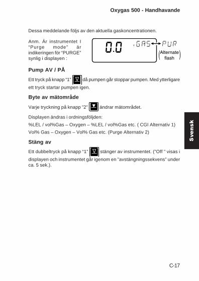
Oxygas 500 - Handhavande
Dessa meddelande följs av den aktuella gaskoncentrationen.
Anm. Är instrumentet I“Purge mode” ärindikeringen för “PURGE”synlig i displayen :
Pump AV / PÅ
Ett tryck på knapp “1” då pumpen går stoppar pumpen. Med ytterligare
ett tryck startar pumpen igen.
Byte av mätområde
Varje tryckning på knapp ”2” ändrar mätområdet.
Displayen ändras i ordningsföljden:
%LEL / vol%Gas – Oxygen – %LEL / vol%Gas etc. ( CGI Alternativ 1)
Vol% Gas – Oxygen – Vol% Gas etc. (Purge Alternativ 2)
Stäng av
Ett dubbeltryck på knapp “1” stänger av instrumentet. (”Off ” visas i
displayen och instrumentet går igenom en ”avstängningssekvens” underca. 5 sek.).
Alternateflash( )
V
Svensk

C-18
GAS MEASUREMENT INSTRUMENTS LTD.
Tjek liste1. Tjek at instrumentet ikke har nogle åbenlyse fejl.3. Tjek tilbehør.4. Læs og forstå burger manualen før brug.5. Tænd instrumentet6. Tjek batteriet level.7. Tænd altid og nulstil i frisk luft.
Sikkerhed• Instrumentet skal regelmæssigt serviceres og kalibreres af
autoriseret personale.• Opladning af batterier skal ske i et sikkert rum.• Tjek batteriet sidder rigtigt fast på instrumentet før brug.• Udsæt aldrig batteri eller instrumentet for ekstrem varme.• Brug kun GMI reserve dele til instrumentet.• Hvis instrumentet konstatere gas, følg da de procedure
som din organisation har foreskrevet.• Forbrændings kammer er brandsikker tilbehør, og må ikke
åbnes i almindelig atmosfære.• Ethvert krav i forbindelse med produkt ansvar eller følge skade
på tredje part imod GMI, er fjernet hvis de ovenståendeforskrivelser ikke håndhæves.
• Oxygas 500 instrument er certificeret ifølge:EEx iad IIC T4 (-20oC < Tamb < 50oC).
BAS01ATEX2292 II 2 G
UL Class 1 Groups A, B, C and D.
Bruger områder
Afdækning af bestemte kemikalier kan resultere i tab af følsomheden iLEL sensoren. Hvor disse omgivelser er kendte eller mistænkt, anbefalesdet at foretage målinger oftere. Den kemiske sammensætning som kanresultere i tab af følsomhed, inkludere silikoner, bly, halogen og svovl.Brug ikke instrumentet ved potentiel farlig atmosfære, der indeholdermere end 21 % ilt.

C-19
Bruger beskeder og fejl
Forskellige beskeder/tegn forekomme på displayet under brug.
‘SAMPLE’ fortæller at pumpen kører, og at instrumentet optager prøver.
‘OFF’ Indikerer at instrumentet er ved at slukke. Denne kommando kanafbrydes ved et tryk på en anden knap.
‘SAMPLE FAULT’ Fortæller at der er et problem under prøve sugning,som kan være følgende: opsugning af skidt, vand, filter blokering ellereb fejl i pumpen. Under måling og ”purge” stopper pumpen automatisk.Tjek for disse fejl, og tryk på knap 1 for at genstarte pumpen.
‘CHECK ZERO’ Indikerer at der måske har været en fejl under måling.Sluk instrumentet og tænd igen i frisk luft.
‘ZERO FAULT’ Indikerer at nul grænsen er uden for kalibreringsområdet. Sluk instrumentet og tænd igen i frisk luft. Hvis fejlen ikke ervæk, send instrumentet til service.
‘BAT’ Fortæller at batteriet snart løber tør for strøm. Alt efter kvalitetenat Alkaline batterier, vil der ca. vil være 60 minutter tilbage. Medgenopladelige batterier er der ca. 30 minutter tilbage. Efter strømmenher fra falder, begynder `BAT FAULT` at blikke. Efter noget tid slukkesinstrumentet automatisk.
‘BAT FAULT’ Fortæller at batteriet straks skal skiftes.
‘1’ Kan fremkomme efter opstart, betyder at der er en kalibrering fejl.Instrumentet skal sendes til service.
Oxygas 500 - Bruger manual
Dansk

C-20
GAS MEASUREMENT INSTRUMENTS LTD.
KNAP 1
KNAP 2OXYGAS 500
ON OFFPUMP
ON OFFINST.
RANGE
PURGE
CGI
ON
CGI Mode 1, LEL/Volume Gas; Ilt
Tryk og hold nede den knap 1 , så startes opvarmnings processen og
pumpen.
Purge Mode 2, 0-100 Volume Gas; Ilt, til purge
Tryk og hold nede den knap 2
, så startes opvarmnings
processen og pumpen.
Under opvarmningidentificeres:
model, serienummer, softwareversion,
batteristatus,
Tænd Oxygas
%VSAMPLE STORE
ZEROFAULT
CHECKBAT
10000PPM80006000400020000
V
BAT
Alternateflash( )
kalibrerings måned og år.

C-21
Oxygas 500 - Bruger manual
Herefter vil displayet begynde at vise målinger.
Bemærk at nårinstrumentet er i ”purge”mode, vil ”purge” blinkepå displayet.
Pumpe
Et tryk på knap 1 , når pumpen kører, stopper pumpen og målingen.
Et tryk mere på knap 1 starter pumpen og målingen igen.
Skifte måling
Et hvert tryk på knap 2 , og gas målingen skifter.
Displayet viser målingerne på følger måde:
LEL/Vol.Gas – Ilt – LEL/Vol.Gas, ect. (CGI mode 1)
Vol.Gas – Ilt – Vol.Gas, ect. (Purge mode 2)
Sluk Oxygas
Tryk 2 gange på knap 1 .
Alternateflash( )
V
Dansk
C-22
GAS MEASUREMENT INSTRUMENTS LTD.
CHECKLIST1. Kijk na of het instrument geen zichtbare fouten vertoont.2. Kijk de accessoires na.3. Lees en begrijp het handboek voor gebruik.4. Schakel het toestel aan (zie volgende bladzijde).5. Kijk het batterijniveau na.6. Controleer “NUL” in open lucht.
VEILIGHEID• De instrumenten moeten regelmatig nagekeken en
gekalibreerd worden door daartoe opgeleid personeel ineen veilig lokaal.
• Batterijen: Alkaline batterijen en herlaadbare batterijenmoeten vervangen en heropgeladen worden in een veiligeomgeving en moeten precies passen voor gebruik. Gebruiknooit beschadigde batterijen of stel ze niet aan extremehitte bloot.
• Alleen GMI wisselstukken mogen gebruikt worden.• Indien het instrument gas detecteert, volg dan uw eigen
bedrijfsprocedure en gebruiksaanwijzing.• De verbrandingskamer is een brandvrij onderdeel en mag
niet geopend worden in een ontvlambare atmosfeer.• Oxygas 500 instrumenten zijn gecertifieerd zoals
EEx iad IIC T4 (-20oC < Tamb < 50oC).
BAS01ATEX2292 II 2 G.
UL Klasse 1 Groepen A, B, C en D.
• Dit toestel is ontwikkeld en gemaakt om ons tebeschermen tegen voorvallen zoals beschreven inparagraaf 1.2.7 van Annex II van de ATEX 94/9/EC
Elke recht op een claim met betrekking tot de betrouwbaarheid ofde daardoor veroorzaakte schade van welke derde partij dan ookaan GMI zal verworpen worden indien de waarschuwingen genegeerdzijn.
PLAATSEN VAN GEBRUIK
Blootstelling aan bepaalde chemicaliën kan resulteren in een verliesvan gevoeligheid van de brandsensor. Indien deze omgevingenbekend zijn of vermoed worden, is het aanbevolen om meerfrequente check-ups uit te voeren. Chemische stoffen die een

C-23
Oxygas 500 - Gebruiksaanwijzing
verlies van gevoeligheid kunnen veroorzaken zijn siliconen, lood,halogenen en zwavel. Gebruik het instrument niet in een schadelijkeatmosfeer met meer dan 21 % zuurstof. Het omhullende materiaal ispolypropyleen en dit mag niet blootgesteld worden aan omgevingen diewaarschijnlijk resulteren in mechanische of thermische degradatie ofschade veroorzaakt door contact met aggressieve substanties.Bijkomende bescherming kan nodig zijn in omgevingen waar hetomhulsel van het instrument onderhavig kan zijn aan schade.
GEBRUIKSBOODSCHAPPEN / FOUTMELDINGEN
Verschillende boodschappen kunnen op het LCD scherm verschijnenom de status van het instrument aan te duiden.
‘SAMPLE’ Indicatie dat de pomp draait en dat het instrument meet.
’OFF’ Indicatie dat het instrument bijna gaat uitschakelen. Dit kangeannuleerd worden door een enkele druk op eendert welke knop.
‘SAMPLE FAULT’ Indicatie van een probleem met de instroom vanhet instrument doordat de invoer geblokkeerd is, door waterinsijpeling,een verstopte filter of falen van de pomp. Bij meting stopt de pompautomatisch. De invoer, filters etc. moeten gecontroleerd worden opwaterinsijpeling of verstopping en knop één moet dan ingeduwd wordenom de pomp te herstarten.
‘CHECK ZERO’ Indicatie dat het nulpunt gewijzigd kan zijn door deaanwezigheid van gas. Schakel het instrument uit en opnieuw aan infrisse lucht.
‘ZERO FAULT’ Indicatie dat het nulpunt buiten de kalibratielimietenvalt. Schakel het instrument uit en opnieuw aan in frisse lucht. Indien defoutmelding niet verdwijnt, breng het toestel terug voor onderhoud.
‘BAT’ Indicatie dat de batterijen weldra aan vervanging toe zijn. Nuresten er nog ongeveer 60 minuten met alkaline batterijen, alhoewel diterg afhankelijk is van de batterijenproducent, temperatuur, gebruik etc.Met herlaadbare batterijen duidt ‘BAT’ nog ongeveer 30 minutenresterende gebruiksduur aan. Naarmate de batterijkracht daalt, knippertop het LCD scherm ‘BAT FAULT’. Daarna zal de LCD automatisch ‘OFF’vertonen en schakelt het toestel zelf uit. De batterijen moeten danonmiddellijk vervangen worden.
‘BAT FAULT’ Indicatie dat de batterijen onmiddellijk moeten vervangenworden.
‘1’ Indicatie, die ook na aanschakelen van de stroom kan verschijnen,dat een kalibratiegegevensfout werd opgespoord. Het instrument moetbinnen voor onderhoud.
Nederlands

C-24
GAS MEASUREMENT INSTRUMENTS LTD.
KNOP 1
KNOP 2OXYGAS 500
ON OFFPUMP
ON OFFINST.
RANGE
PURGE
CGI
ON
V
GEBRUIK
Schakel AAN (CGI Mode 1)LEL autobereik naar volume gas ; zuurstof.
Druk op knop 1 en houdt ingedrukt om instrument en pomp aan te
schakelen. Dit zorgt voor opwarming.
Schakel AAN (Purge Mode 2)
Alle getoonde LCD segmentenworden gevolgd door het instumenttype en de software versie,
en daarna de batterij status,zoals getoond:
Dan toont hetinstrument, met maanden jaar, wanneer devolgende kalibratie moetplaatsvinden. (februari2005 bijvoorbeeld)
Alle LCD segmenten wordengetoond.
%VSAMPLE STORE
ZEROFAULT
CHECKBAT
10000PPM80006000400020000
BAT
( )Afwisselendknipperlicht
0 tot 100% volume gas ; zuurstof,voor reinigingstoepassingen.
Druk op knop 2 en houdt
ingedrukt om instrument en pompaan te schakelen. Dit zorgt vooropwarming.

C-25
Oxygas 500 - Gebruiksaanwijzing
Het CAL DUE scherm wordt gevolgd door het huidig gedetecteerde gas.
Pomp AAN / UIT
Een enkele druk op knop 1 wanneer de pomp draait, schakelt de
pomp uit en stopt het meten. Een volgende druk op knop 1 schakelt depomp weer aan.
Aanpassen bereik
Elke enkele druk op knop 2 wijzigt het gasbereik.
De display laat de mogelijke bereiken zien in volgorde:
LEL/Vol.Gas – zuurstof – LEL/Vol.Gas, etc. (CGI Mode 1)
Vol. Gas – zuurstog – Vol. Gas, etc. (Purge Mode 2).
Schakel UIT
Een dubbele druk op knop 1 schakelt het instrument uit.
Nota: In dereinigingstoestand is dePURGE geactiveerd,zoals getoond:
V
( )Afwisselendknipperlicht
Nederlands

C-26
GAS MEASUREMENT INSTRUMENTS LTD.

C-27
Greek

C-28
GAS MEASUREMENT INSTRUMENTS LTD.

C-29
Greek

C-30
GAS MEASUREMENT INSTRUMENTS LTD.

I
Index
Symbols
1 25
A
ACCESSORIES 37Accuracy A-1ADDITIONAL INFORMATION
41ADVICE, DISPOSAL ialkaline A-3Alkaline (LR20) Dry Cell
Batteries 15AREAS OF USE ii
B
BAT 25BAT FAULT 25Batteries 15Battery Pack
16, 27, 29, 30Before Use Checks 17Button Operation 23
C
CALIBRATION 35, B-1Calibration Date Features
21
Calibration Procedure B-5CALIBRATION VALIDITY 35Calibration Validity 34, 36Changing Range 23Charger, Flatbed 28Charger, Smart 28Charger, Standard 27CHECK ZERO 24Combustible Gas Indicator -
Leak Detection 2Commissioning 6CONFORMITY iiiConstruction 15, A-2COPYRIGHT i
D
Dansk (Danish) x, C-1De-commissioning 7DECLARATION OF
CONFORMITY iiiDeutsch (German) C-1Direct Purging 7Display A-2Disposable Alkaline (LR20)
Dry Cell Batteries 15DISPOSAL ADVICE i

OXYGAS 500 USER HANDBOOK
II
E
EN 50104 A-2English x, C-1Entering FCM B-3
F
FAULT, BAT 25Fault Flags 24FAULT, SAMPLE 24FAULT, ZERO 24FCM B-1, B-3, B-9features 11FIELD CALIBRATION B-1Field Calibration Procedure
B-5Filter Replacement 32Filters 16Flatbed Charger 28Français (French) x
G
GENERAL INFORMATION13
H
HANDLING iiHumidity A-2
I
IMS 35Indirect Purging 9
INFORMATION,ADDITIONAL 41
INFORMATION, GENERAL13
INSTRUCTIONS,OPERATING C-1
Instrument Pump 21INTRODUCTION 1
L
LCD 17, A-2LEL, 0 to 100% 13LIABILITY iLiquid Crystal Display 17L'italiano (Italian) x, C-1
M
MAINTENANCE, OPERATOR27
Messages, Operator 24Modes of Operation 19MODIFICATION NOTICES i
N
Nederlands (Dutch) x, C-1NiCd A-3NOTICES, MODIFICATION i
O
OFF 24OPERATING INSTRUCTIONS
19, C-1

III
OPERATING PARAMETERSA-1
Operating Temperature A-2OPERATOR MAINTENANCE
27Operator Messages 24Overview 2Oxygen 14
P
PARAMETERS, OPERATINGA-1
Power Source A-3Pump, Instrument 21Purge Mode 22Purging 4Purging, Direct 7Purging, Indirect 9
Q
Quit And Save Changes B-9
Quit Without SavingChanges B-9
Quitting FCM B-9
R
Range, Changing 23ranges 1Ranges of Operation 13Rechargeable Battery Pack
16, 27
Recharging the BatteryPack 30
Replacement, Filter 32Replacing Alkaline (LR20)
Dry Cell Batteries 30Replacing the Battery Pack
29Resolution A-1Response Time (O2) A-2REVISION RECORD v
S
SAFETY iiSAMPLE 24SAMPLE FAULT 24, 32Sampling System A-2Save Changes B-9Selectable Ranges in FCM
B-2Size A-2Smart Charger 28SOFTWARE iSource, Power A-3Standard Charger 27STORAGE iiSummary of Button
Operation 23Svensk (Swedish) x, C-1Switching Off 22Switching Off the
Instrument Pump 21Switching On 20Switching On in Purge
Mode 22

OXYGAS 500 USER HANDBOOK
IV
T
Time, Response A-2Training 41TRANSIT ii
V
Validity, Calibration 36Volume Gas 14
W
Weight A-2World Wide Web 41
Z
Zero A-1ZERO, CHECK 24ZERO FAULT 24Zeroing the Instrument B-4


GMI Head Office:
Inchinnan Business Park,Renfrew,PA4 9RG,Scotland, U.K.Telephone +44 (0)141 812 3211Fax +44 (0)141 812 7820e-mail: [email protected]://www.gmiuk.com
USA Head Office (Detcon):
4055 Technology Forest Blvd.,Suite 100, The Woodlands,TX 77381, USATelephone (713) 559 9290Toll Free (888) 367 4286Fax (281) 292 2860e-mail: [email protected]
GMI Service & Calibration Division:
25 Cochran Close, Crownhill,Milton Keynes,MK8 OAJ,England, U.K.Telephone +44 (0)1908 568867Fax +44 (0)1908 261056e-mail: [email protected]