Embed Size (px)
Citation preview
P Lamalle, A Messiaen et al ICRH CT matching satellite meeting , 23rd SOFT, Venice, 21 September 2004
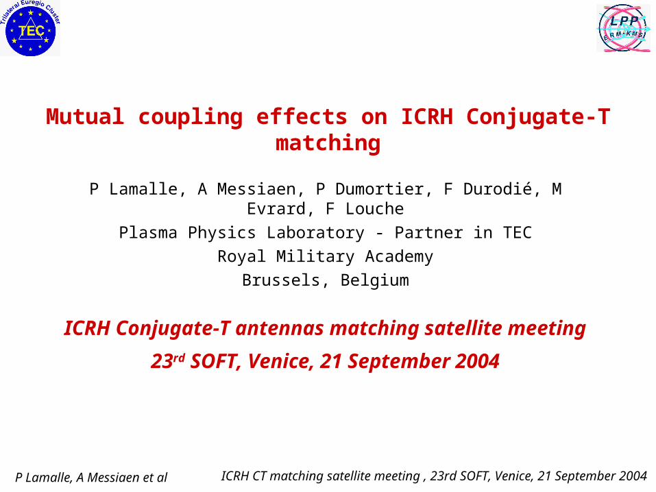
Mutual coupling effects on ICRH Conjugate-T matching
P Lamalle, A Messiaen, P Dumortier, F Durodié, M Evrard, F Louche
Plasma Physics Laboratory - Partner in TEC
Royal Military Academy
Brussels, Belgium
ICRH Conjugate-T antennas matching satellite meeting
23rd SOFT, Venice, 21 September 2004

P Lamalle, A Messiaen et al ICRH CT matching satellite meeting , 23rd SOFT, Venice, 21 September 2004
Outline
Investigation of mutual coupling effects on conjugate T (CT) matching:
• General properties of ICRH array impedance matrices;
• Model of several CT circuits mutually coupled via the antenna straps;
• New results: optimization of load tolerance for the single CT circuit
with mutual;
• Specific problems resulting from coupling between several CTs,
possible remedies. [NB parts of this section already presented at Ringberg
meetings in April and JET-EP design review in June 2004]

P Lamalle, A Messiaen et al ICRH CT matching satellite meeting , 23rd SOFT, Venice, 21 September 2004
Properties of ICRH array impedance matrices
• N-port antenna array n by n input impedance matrix ZA = RA+ jXA
• Input voltages and currents: arrays VA, IA , VA = ZA IA
• Mutual impedances ZAik=RAik+jXAik between straps i and k (ik):
– Nonzero resistive part RAik, due to interference of the field components
radiated by each strap, contributes to the radiated active power.
Responsible for the strong experimental dependence of antenna port
loading on toroidal phasing of the straps observed on ICRH arrays;
– XAik induces power transfer between straps i and k.
– Complex power Pi delivered by the external sources to strap i:
2* *2 ( ) ( )i Ai Ai Aii Aii Ai Aik Aik Ai Akk i
P I V R jX I R jX I I
P Lamalle, A Messiaen et al ICRH CT matching satellite meeting , 23rd SOFT, Venice, 21 September 2004
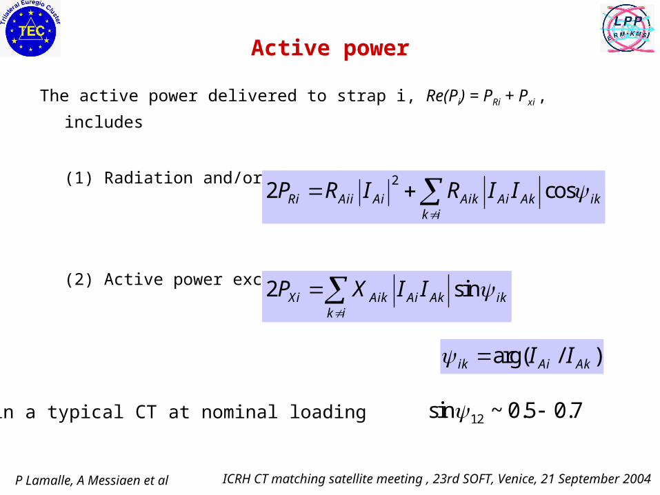
Active power
The active power delivered to strap i, Re(Pi) = PRi + Pxi , includes
(1) Radiation and/or ohmic dissipation:
(2) Active power exchanged between straps:
22 cosRi Aii Ai Aik Ai Ak ik
k i
P R I R I I
2 sinXi Aik Ai Ak ikk i
P X I I
arg( / )ik Ai AkI I
NB: within a typical CT at nominal loading !12sin ~ 0.5 0.7

P Lamalle, A Messiaen et al ICRH CT matching satellite meeting , 23rd SOFT, Venice, 21 September 2004
Mutual coupling is generally responsible for
• An unbalance of power distribution between antenna ports (see next fig.)
(even when the straps are geometrically identical);
• Coupling between the power sources if the array is simultaneously fed
by different sources.
P Lamalle, A Messiaen et al ICRH CT matching satellite meeting , 23rd SOFT, Venice, 21 September 2004
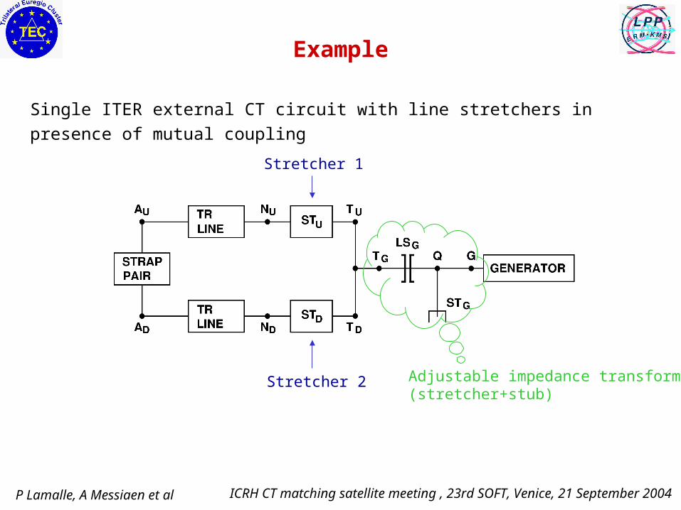
Example
Single ITER external CT circuit with line stretchers in presence of mutual coupling
Stretcher 1
Stretcher 2 Adjustable impedance transformer(stretcher+stub)

P Lamalle, A Messiaen et al ICRH CT matching satellite meeting , 23rd SOFT, Venice, 21 September 2004
Active power sharing between the 2 CT branches, showing the large power exchange due to the mutual reactance.
Exchanged
Total active (branch 2)
Total active (branch 1)
Radiated (branch 1)
Radiated (branch 2)
Active power sharing
Load scaling factor(ELM-like perturbation)

P Lamalle, A Messiaen et al ICRH CT matching satellite meeting , 23rd SOFT, Venice, 21 September 2004
Other features of ZA= RA+j XA
• RA is positive definite.
• The signs of the mutual coefficients depend on the relative orientations of the radiating current loops.
• Simulations including plasma gyrotropic effects (Colas, EPS 2004) may yield nonsymmetric ZA (with the main effect on RA) and enhance
dissymmetries.
• The antenna data used in the following simulations were either obtained by 3D electromagnetic simulations of the ITER array (Louche, EPS 2004), or from measurements on a scaled mockup (see A. Messiaen, P3T-B-211)
P Lamalle, A Messiaen et al ICRH CT matching satellite meeting , 23rd SOFT, Venice, 21 September 2004
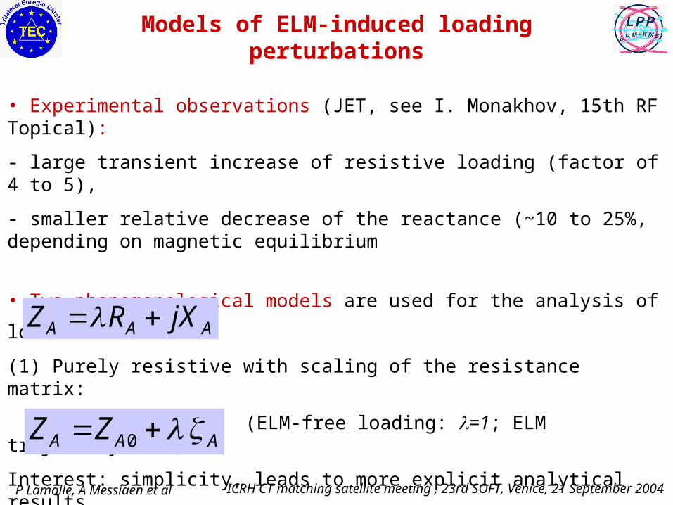
Models of ELM-induced loading perturbations
• Experimental observations (JET, see I. Monakhov, 15th RF Topical):
- large transient increase of resistive loading (factor of 4 to 5),
- smaller relative decrease of the reactance (~10 to 25%, depending on magnetic equilibrium
• Two phenomenological models are used for the analysis of load tolerance:
(1) Purely resistive with scaling of the resistance matrix:
(ELM-free loading: =1; ELM trajectory: 1)
Interest: simplicity, leads to more explicit analytical results.
(2) General first-order model: perturbation matrix A may include reactive terms
(ELM-free loading: =0; ELM trajectory: 0)
Allows a realistic account of experimental data.
A A AZ R jX
0A A AZ Z

P Lamalle, A Messiaen et al ICRH CT matching satellite meeting , 23rd SOFT, Venice, 21 September 2004
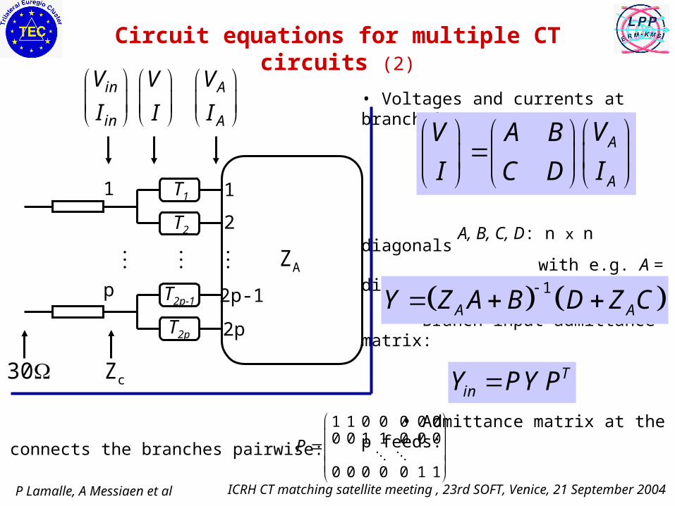
Circuit equations for multiple CT circuits (1)
n=2p antenna ports connected in pairs through n independent matching circuits to p feed ports.
Each branch matching circuit is lossless & reciprocal, and has a transfer matrix
(ai, di real, bi, ci imaginary, ai di - bi ci =1)
For series capacitors: ai = di = 1, bi = 1/(jCi), ci = 0
For line stretchers:
ai = di = cosli , -jbi / Z0 = -jZ0ci = sinli
Other circuits or nonideal effects are easily
included in Ti.
ZA
1
2
2p-1
2p
1
p
A
A
V
I
in
in
V
I
V
I
30 Zc
T1
T2
T2p
T2p-1
i ii
i i
a bT
c d
P Lamalle, A Messiaen et al ICRH CT matching satellite meeting , 23rd SOFT, Venice, 21 September 2004
• Voltages and currents at branch inputs:
A, B, C, D: n x n diagonals with e.g. A = diag(ai, i=1,n)
• Branch input admittance matrix:
• Admittance matrix at the p feeds:
Circuit equations for multiple CT circuits (2)
ZA
1
2
2p-1
2p
1
p
A
A
V
I
in
in
V
I
V
I
30 Zc
T1
T2
T2p
T2p-1
A
A
VV A B
II C D
1
A AY Z A B D Z C
TinY PY P
• P connects the branches pairwise:
1 1 0 0 0 0 00 0 1 1 0 0 0
0 0 0 0 0 1 1
P

P Lamalle, A Messiaen et al ICRH CT matching satellite meeting , 23rd SOFT, Venice, 21 September 2004
• Matching conditions: given - reference admittance Yc =1/Zc, - array loading (reference ),- feeding mode (e.g.Vin array, relative mag. & ),
• Complex polynomial system of order p and degree 2p for the matching transfer parameters {ai, bi, ci }
• There are 2p unknowns if each circuit has 1 adjustable parameter.
(NB Ti has max. 3 independent
parameters additional design freedom is available)
Circuit equations for multiple CT circuits (3)
ZA
1
2
2p-1
2p
1
p
A
A
V
I
in
in
V
I
V
I
30 Zc
T1
T2
T2p
T2p-1
( )in in in c inI Y V Y V
P Lamalle, A Messiaen et al ICRH CT matching satellite meeting , 23rd SOFT, Venice, 21 September 2004
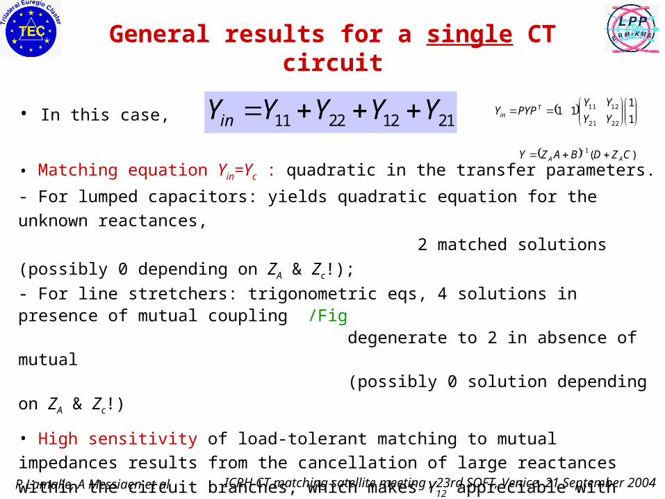
General results for a single CT circuit
• In this case,
• Matching equation Yin=Yc : quadratic in the transfer parameters.
- For lumped capacitors: yields quadratic equation for the unknown reactances,
2 matched solutions (possibly 0 depending on ZA & Zc!);
- For line stretchers: trigonometric eqs, 4 solutions in presence of mutual coupling /Fig degenerate to 2 in absence of mutual (possibly 0 solution depending on ZA & Zc!)
• High sensitivity of load-tolerant matching to mutual impedances results from the
cancellation of large reactances within the circuit branches, which makes Y12
appreciable with respect to Y11 although at the antenna straps |Z12A|<<|Z11A|.
• The cancellation is more and more delicate as Zc (explains why this sensitivity is so
much higher with CT load resilient schemes than with standard matching)
11 22 12 21inY Y Y Y Y
1
111
2221
1211
YY
YYPYPY T
in
)(1 CZDBAZY AA
P Lamalle, A Messiaen et al ICRH CT matching satellite meeting , 23rd SOFT, Venice, 21 September 2004
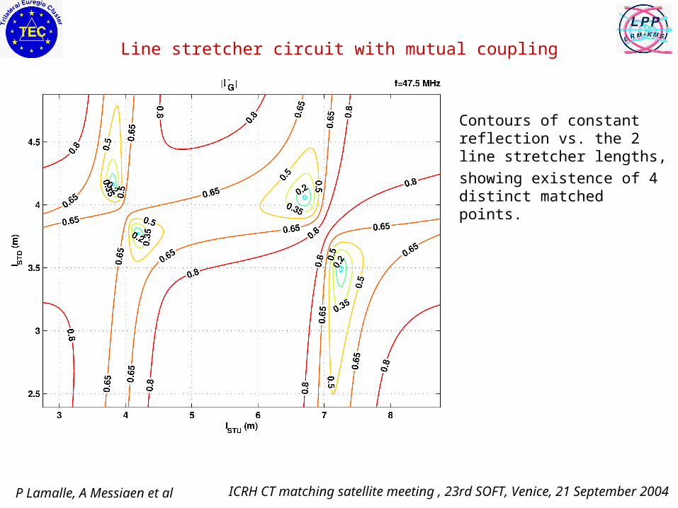
Line stretcher circuit with mutual coupling
Contours of constant reflection vs. the 2 line stretcher lengths,
showing existence of 4 distinct matched points.
P Lamalle, A Messiaen et al ICRH CT matching satellite meeting , 23rd SOFT, Venice, 21 September 2004
Optimization of load resilience (single CT circuit)
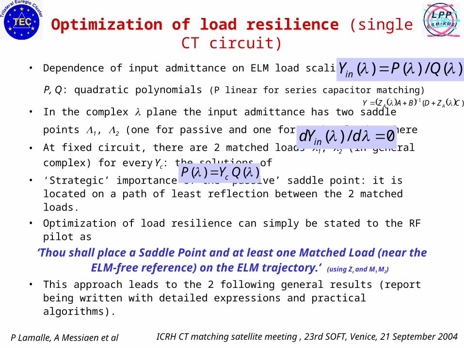
• Dependence of input admittance on ELM load scaling :
P, Q: quadratic polynomials (P linear for series capacitor matching)
• In the complex plane the input admittance has two saddle points 1, 2
(one for passive and one for active loads) where
• At fixed circuit, there are 2 matched loads 1, 2 (in general complex) for
every Yc: the solutions of
• ‘Strategic’ importance of the ‘passive’ saddle point: it is located on a path of least reflection between the 2 matched loads.
• Optimization of load resilience can simply be stated to the RF pilot as
‘Thou shall place a Saddle Point and at least one Matched Load (near the ELM-free reference) on the
ELM trajectory.’ (using Zc and M1 M2)
• This approach leads to the 2 following general results (report being written with detailed expressions and practical algorithms).
( ) / 0indY d
( ) ( ) / ( )inY P Q
( ) ( )cP Y Q
)(1 CZDBAZY AA
P Lamalle, A Messiaen et al ICRH CT matching satellite meeting , 23rd SOFT, Venice, 21 September 2004
Result 1: For resistive load perturbations,
0 5 10 151
1.5
2
2.5
3
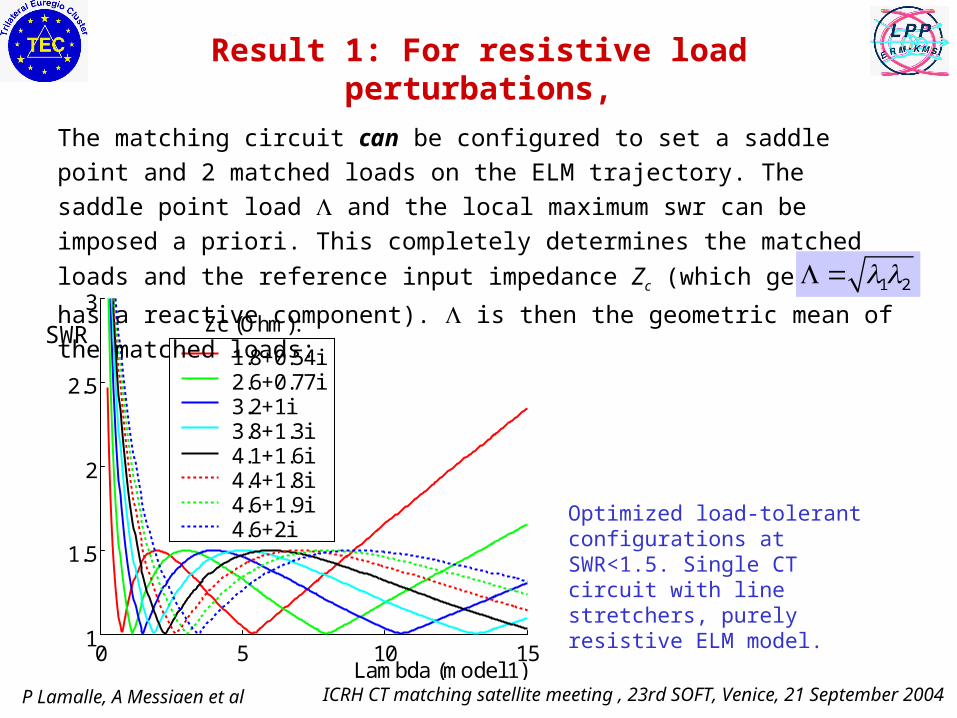
1.8+0.54i2.6+0.77i3.2+1i3.8+1.3i4.1+1.6i4.4+1.8i4.6+1.9i4.6+2i
Zc (Ohm):
Lambda (model 1)
SWR
The matching circuit can be configured to set a saddle point and 2 matched
loads on the ELM trajectory. The saddle point load and the local maximum
swr can be imposed a priori. This completely determines the matched loads
and the reference input impedance Zc (which generally has a reactive
component). is then the geometric mean of the matched loads:
Optimized load-tolerant configurations at SWR<1.5. Single CT circuit with line stretchers, purely resistive ELM model.
1 2
P Lamalle, A Messiaen et al ICRH CT matching satellite meeting , 23rd SOFT, Venice, 21 September 2004
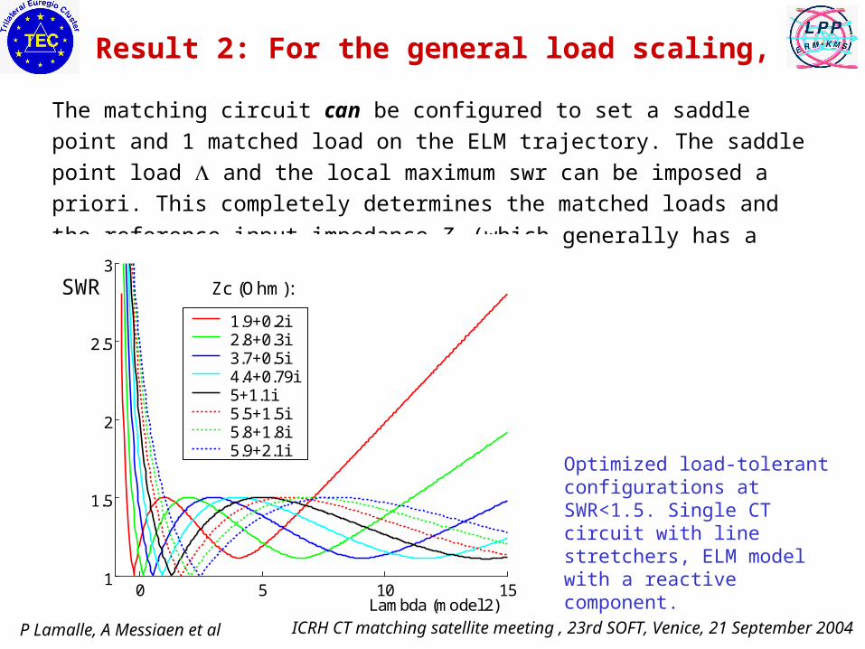
The matching circuit can be configured to set a saddle point and 1 matched
load on the ELM trajectory. The saddle point load and the local maximum swr
can be imposed a priori. This completely determines the matched loads and the
reference input impedance Zc (which generally has a reactive component).
Result 2: For the general load scaling,
Optimized load-tolerant configurations at SWR<1.5. Single CT circuit with line stretchers, ELM model with a reactive component.
0 5 10 151
1.5
2
2.5
3
1.9+0.2i2.8+0.3i3.7+0.5i4.4+0.79i5+1.1i5.5+1.5i5.8+1.8i5.9+2.1i
Zc (Ohm):
Lambda (model 2)
SWR

P Lamalle, A Messiaen et al ICRH CT matching satellite meeting , 23rd SOFT, Venice, 21 September 2004
• The underlying equations are valid for any lossless matching circuit and any antenna
(incl. mutual, dissymmetries, gyrotropic effects). They generalize earlier analytical
results obtained for uncoupled antenna straps and lumped capacitors.
• (Currently attempting to generalize this to several coupled CTs.)
• In both models achieving the optimal resilience settings generally requires a complex
reference impedance Zc=1/Yc, which plays the role of 2 additional tuning parameters
(i.e., the transformer settings required to match this Zc to 30).
• In such configurations the active power exchange between CT branches is reduced.
Strong interest for an adjustable transformer stage between the CT connection and
the main transmission line: allows operation of the system with a complex impedance
at the T ensuring best load tolerance at each operating frequency. To be tested on
JET-A2, TEXTOR, JET-IL where this freedom exists.
• Possibilities of implementation on ITER should be investigated with high priority.
Single CT - optimized load resilience - Discussion

P Lamalle, A Messiaen et al ICRH CT matching satellite meeting , 23rd SOFT, Venice, 21 September 2004
• Goal of ongoing study: finding ‘all’ matched ELM-free configurations.
• Tools: (1) basic continuation methods; (2) advanced polynomial system solvers (spinoff from robotics, economics, chemistry and pure math.)
• The number of solutions depends on strap dissymmetries, strength of mutual coupling (Fig.), array phasing (all features able to lift degeneracies from the system), and on the reference Zc. This can make obvious tracking
methods (e.g. decreasing Zc from a high initial value, for which mutual
effects are less critical) unreliable to find matched settings.
• For large ratios |mutual|/ Zc there may be no solution; for the whole array of 4 coupled CTs tens of solutions may be found. Only a few, sometimes just one, of these solutions are physically attractive (i.e. within operational limits and with proper strap current phasing).
• This raises basic practical questions: selection and implementation of the best solution on the ICRH plant, with only approximate knowledge of the antenna impedance matrix; avoiding attraction of automatic control system by undesired solutions, etc.
Specific effects for several CT circuits
P Lamalle, A Messiaen et al ICRH CT matching satellite meeting , 23rd SOFT, Venice, 21 September 2004
0 0.5 1-0.4
-0.3
-0.2
-0.1
0
0.1
0.2
0.3
0.4Solution #2 - not OK
0 0.5 1-0.5
-0.25
0
0.25
0.5Solution #6 - OK
x x
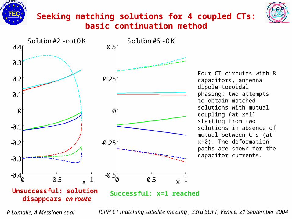
Seeking matching solutions for 4 coupled CTs: basic continuation method
Four CT circuits with 8 capacitors, antenna dipole toroidal phasing: two attempts to obtain matched solutions with mutual coupling (at x=1) starting from two solutions in absence of mutual between CTs (at x=0). The deformation paths are shown for the capacitor currents.
Unsuccessful: solution disappears en route
Successful: x=1 reached
P Lamalle, A Messiaen et al ICRH CT matching satellite meeting , 23rd SOFT, Venice, 21 September 2004
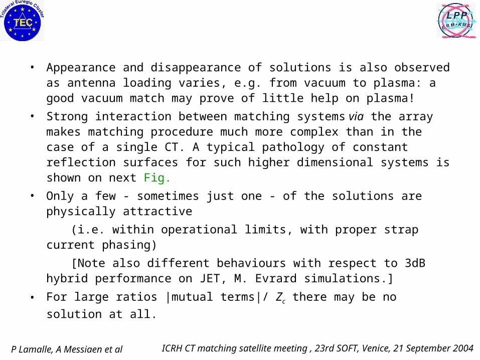
• Appearance and disappearance of solutions is also observed as antenna loading varies, e.g. from vacuum to plasma: a good vacuum match may prove of little help on plasma!
• Strong interaction between matching systems via the array makes matching procedure much more complex than in the case of a single CT. A typical pathology of constant reflection surfaces for such higher dimensional systems is shown on next Fig.
• Only a few - sometimes just one - of the solutions are physically attractive
(i.e. within operational limits, with proper strap current phasing)
[Note also different behaviours with respect to 3dB hybrid performance on JET, M. Evrard simulations.]
• For large ratios |mutual terms|/ Zc there may be no solution at all.

P Lamalle, A Messiaen et al ICRH CT matching satellite meeting , 23rd SOFT, Venice, 21 September 2004
x2
x3
x1x2
x3
x1
Constant reflection surfaces for 2 coupled CTs
Feed line 1 (x1, x2):
SWR=1.5
Feed line 2 (x3, x4):
SWR=1.5
Two coupled CT circuits with 4 capacitors (reactances xi): Surfaces of constant input SWR=1.5 at each feed vs (x1,x2,x3). x4 is linearly constrained by x1, x2, x3 to locate 4 matched solutions in a 3D view. Note the strong influence of x3 (located in CT#2) on feed line #1 in a limited interval. Dipole antenna phasing, Zc=3.
Pathology due to mutual
Single CT-like behaviour:cylindrical along x3
P Lamalle, A Messiaen et al ICRH CT matching satellite meeting , 23rd SOFT, Venice, 21 September 2004
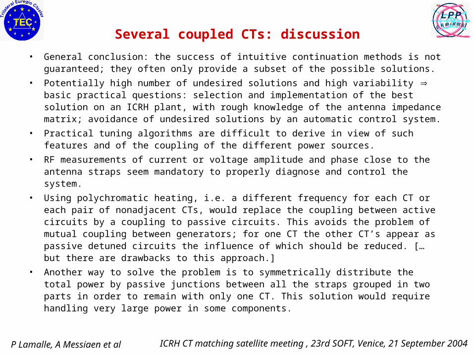
Several coupled CTs: discussion
• General conclusion: the success of intuitive continuation methods is not guaranteed; they often only provide a subset of the possible solutions.
• Potentially high number of undesired solutions and high variability basic practical questions: selection and implementation of the best solution on an ICRH plant, with rough knowledge of the antenna impedance matrix; avoidance of undesired solutions by an automatic control system.
• Practical tuning algorithms are difficult to derive in view of such features and of the coupling of the different power sources.
• RF measurements of current or voltage amplitude and phase close to the antenna straps seem mandatory to properly diagnose and control the system.
• Using polychromatic heating, i.e. a different frequency for each CT or each pair of nonadjacent CTs, would replace the coupling between active circuits by a coupling to passive circuits. This avoids the problem of mutual coupling between generators; for one CT the other CT’s appear as passive detuned circuits the influence of which should be reduced. [… but there are drawbacks to this approach.]
• Another way to solve the problem is to symmetrically distribute the total power by passive junctions between all the straps grouped in two parts in order to remain with only one CT. This solution would require handling very large power in some components.

P Lamalle, A Messiaen et al ICRH CT matching satellite meeting , 23rd SOFT, Venice, 21 September 2004
Conclusions
• By all means, an interesting topic!
• Significant progress in the detailed understanding and optimisation of the general single CT circuit with mutual coupling [achieved by a ‘shift of emphasis’ to the admittance saddle point instead of the matched load]
• There is much to win in relaxing the reality of Zc should develop an adjustable impedance transformer for integration on ITER. [Review after tests on present systems: possibility to design a fixed ‘nonstandard’ one?]
• This approach will soon be applied to multiple CT systems.
• Same basic existential questions as 3 months ago for the latter, but we are making progress!
P Lamalle, A Messiaen et al ICRH CT matching satellite meeting , 23rd SOFT, Venice, 21 September 2004
Question to the Workshop
• Circuit modelling during an ELM: what is really constant?
• Do we need to model the system up to the tetrode (assuming constant
current there)?
• What happens to phase control on these timescales?

P Lamalle, A Messiaen et al ICRH CT matching satellite meeting , 23rd SOFT, Venice, 21 September 2004
P Lamalle, A Messiaen et al ICRH CT matching satellite meeting , 23rd SOFT, Venice, 21 September 2004
Reserve slides
P Lamalle, A Messiaen et al ICRH CT matching satellite meeting , 23rd SOFT, Venice, 21 September 2004
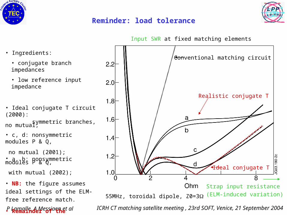
Reminder: load tolerance
Conventional matching circuit
Ideal conjugate T
Input SWR at fixed matching elements
Strap input resistance
(ELM-induced variation) 55MHz, toroidal dipole, Z0=3
• Ingredients:
• conjugate branch impedances
• low reference input impedance
• Ideal conjugate T circuit (2000): symmetric branches, no mutual;
• c, d: nonsymmetric modules P & Q, no mutual (2001);• a, b: nonsymmetric modules P & Q, with mutual (2002);
• NB: the figure assumes ideal
settings of the ELM-free reference
match.
• Remainder of the presentation
addresses the finding of fair
approximations to such settings (and sending the system there)
Realistic conjugate T

P Lamalle, A Messiaen et al ICRH CT matching satellite meeting , 23rd SOFT, Venice, 21 September 2004
-5 0 5 10
-6
-4
-2
0
2
4
6
( -1)
(
-1)
arg(I2/I1) and arg(Vf2/Vf1), degree
-100
-80 -6
0
-40
20
40
6060
8080
100
100
120
140
-100
-80
-60
20
4040
6060
8080 80
100
100
120
140
One pair of straps: voltage probe and branch currents relative phaseSimilar behaviour V probes provide key information in absence of magnetic loops
Blue: arg(Vf2/Vf1)=const
Red: arg(I2/I1)=const
NB: constant current relative phase loci: a family of hyperbolasBranch 1 shifted reactance
Branch 2 shifted reactance
Matched point

P Lamalle, A Messiaen et al ICRH CT matching satellite meeting , 23rd SOFT, Venice, 21 September 2004
0.5 1 1.5 2 2.5 3 3.5 4 4.5 51
1.1
1.2
1.3
1.4
1.5
1.6
1.7
1.8Matching solution #1
Scaling factor
SW
R
Z0=3 Z0=3+0.3i Z0=3+0.6i Z0=3+0.9i Z0=3+1.2i
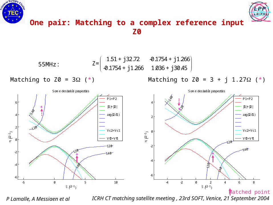
One pair: Matching to a complex reference input Z0
• Aim: reduce current and voltage imbalance in presence of mutual coupling
• OK on JET, where the transformer is adjustable!
• Reassessing load tolerance in this mode of operation:Purely resistive variations: improved tolerance:
P Lamalle, A Messiaen et al ICRH CT matching satellite meeting , 23rd SOFT, Venice, 21 September 2004
Matching to Z0 = 3 + j 1.27 (*)
1.51 + j 32.72 -0.1754 + j 1.266Z=
-0.1754 + j 1.266 1.036 + j 30.45
Matching to Z0 = 3 (*)
55MHz:
One pair: Matching to a complex reference input Z0
-5 0 5 10
-6
-4
-2
0
2
4
6
( -1)
(
-1)
Some desirable properties
-140
-120
120120
140
140
P1=P2 |I1|=|I2| arg(I2/I1) Vc2=Vc1 Vf2=Vf1
-4 -2 0 2 4 6 8
-6
-4
-2
0
2
4
( -1)
(
-1)
Some desirable properties
-140
-120
120
120
140
140
P1=P2 |I1|=|I2| arg(I2/I1) Vc2=Vc1 Vf2=Vf1
Matched point

P Lamalle, A Messiaen et al ICRH CT matching satellite meeting , 23rd SOFT, Venice, 21 September 2004
0 0.2 0.4 0.6 0.8 1-50
-40
-30
-20Solution #1 - OK
0 0.2 0.4 0.6 0.8 1
-40
-20
0
20Solution #2 - not OK
0 0.2 0.4 0.6 0.8 1
-40
-20
0
20Solution #3 - not OK
0 0.2 0.4 0.6 0.8 1-50
-40
-30
-20Solution #4 - OK
0 0.2 0.4 0.6 0.8 1
-40
-20
0
20Solution #5 - not OK
0 0.2 0.4 0.6 0.8 1-40
-30
-20
-10
0Solution #6 - not OK
0 0.2 0.4 0.6 0.8 1
-40
-20
0
20Solution #7 - not OK
0 0.2 0.4 0.6 0.8 1-50
-40
-30
-20
-10
0Solution #8 - not OK
0 0.2 0.4 0.6 0.8 1-40
-30
-20
-10
0Solution #9 - OK
0 0.2 0.4 0.6 0.8 1
-40
-20
0
20Solution #10 - not OK
0 0.2 0.4 0.6 0.8 1-40
-30
-20
-10
0Solution #11 - OK
0 0.2 0.4 0.6 0.8 1
-40
-20
0
20Solution #12 - OK
0 0.2 0.4 0.6 0.8 1-50
-40
-30
-20Solution #13 - not OK
0 0.2 0.4 0.6 0.8 1
-40
-20
0
20Solution #14 - not OK
0 0.2 0.4 0.6 0.8 1-50
-40
-30
-20
-10
0Solution #15 - not OK
0 0.2 0.4 0.6 0.8 1-50
-40
-30
-20Solution #16 - OK
Switching the mutual on / Unknowns: capacitor reactances
Pathologies:- Attraction to (or simply outside feasible capacitance range)- Merging of solutions
P Lamalle, A Messiaen et al ICRH CT matching satellite meeting , 23rd SOFT, Venice, 21 September 2004
0 0.2 0.4 0.6 0.8 1-0.5
0
0.5Solution #1 - OK
0 0.2 0.4 0.6 0.8 1-0.5
0
0.5Solution #2 - OK
0 0.2 0.4 0.6 0.8 1-0.5
0
0.5Solution #3 - OK
0 0.2 0.4 0.6 0.8 1-0.5
0
0.5Solution #4 - OK
0 0.2 0.4 0.6 0.8 1-0.5
0
0.5Solution #5 - OK
0 0.2 0.4 0.6 0.8 1-0.5
0
0.5Solution #6 - not OK
0 0.2 0.4 0.6 0.8 1-0.5
0
0.5Solution #7 - OK
0 0.2 0.4 0.6 0.8 1-0.5
0
0.5Solution #8 - OK
0 0.2 0.4 0.6 0.8 1-0.5
0
0.5Solution #9 - not OK
0 0.2 0.4 0.6 0.8 1-0.5
0
0.5Solution #10 - OK
0 0.2 0.4 0.6 0.8 1-0.5
0
0.5Solution #11 - not OK
0 0.2 0.4 0.6 0.8 1-0.5
0
0.5Solution #12 - OK
0 0.2 0.4 0.6 0.8 1-0.5
0
0.5Solution #13 - OK
0 0.2 0.4 0.6 0.8 1-0.5
0
0.5Solution #14 - not OK
0 0.2 0.4 0.6 0.8 1-0.5
0
0.5Solution #15 - OK
0 0.2 0.4 0.6 0.8 1-0.5
0
0.5Solution #16 - OK
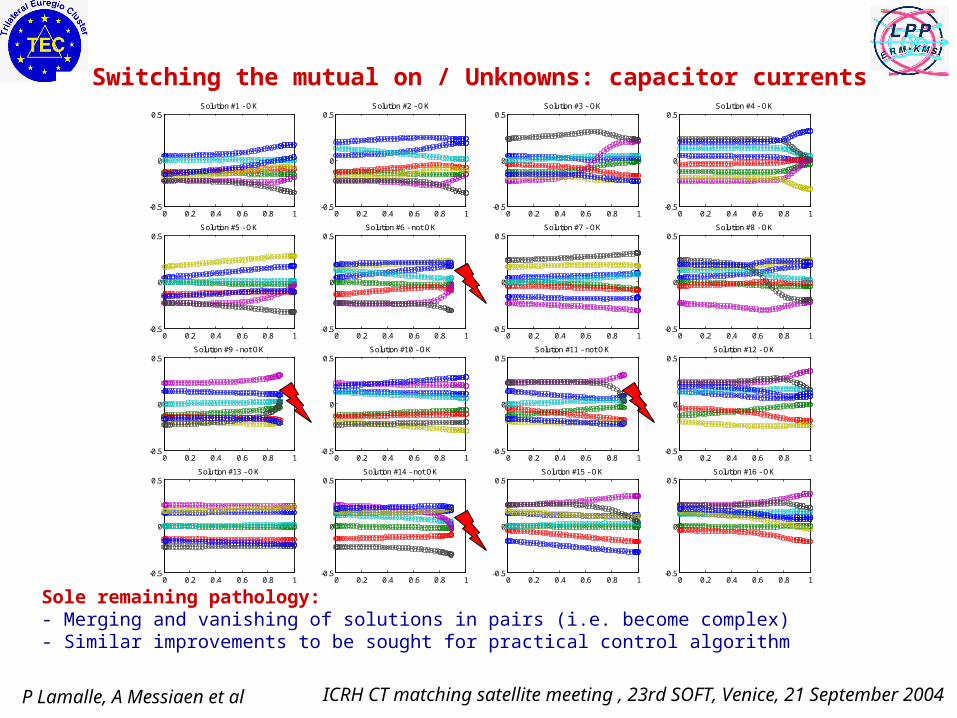
Switching the mutual on / Unknowns: capacitor currents
Sole remaining pathology:- Merging and vanishing of solutions in pairs (i.e. become complex)- Similar improvements to be sought for practical control algorithm

P Lamalle, A Messiaen et al ICRH CT matching satellite meeting , 23rd SOFT, Venice, 21 September 2004
0 0.2 0.4 0.6 0.8 1-4
-2
0
2
4
0 0.05 0.1 0.15 0.2-0.4
-0.2
0
0.2
0.4
0 0.1 0.2 0.3 0.4 0.5-0.5
0
0.5
0 0.02 0.04 0.06 0.08 0.1-0.4
-0.2
0
0.2
0.4
0 0.1 0.2 0.3 0.4-0.4
-0.2
0
0.2
0.4
0 0.1 0.2 0.3 0.4-0.4
-0.2
0
0.2
0.4
0 0.1 0.2 0.3 0.4-0.4
-0.2
0
0.2
0.4
0 0.2 0.4 0.6 0.8 1-4
-2
0
2
4
0 0.1 0.2 0.3 0.4-0.4
-0.2
0
0.2
0.4
0 0.1 0.2 0.3 0.4 0.5-0.5
0
0.5
0 0.2 0.4 0.6 0.8 1-4
-2
0
2
4
0 0.05 0.1 0.15 0.2-0.4
-0.2
0
0.2
0.4
0 0.2 0.4 0.6 0.8 1-4
-2
0
2
4
0 0.05 0.1 0.15 0.2-0.4
-0.2
0
0.2
0.4
0 0.02 0.04 0.06 0.08 0.1-0.4
-0.2
0
0.2
0.4
0 0.1 0.2 0.3 0.4-0.4
-0.2
0
0.2
0.4
0 0.1 0.2 0.3 0.4 0.5-0.5
0
0.5
Connecting plasma to vacuum solutions?Decreasing loading towards vacuum / Unknowns: capacitor currents
Evolution of branch currents from 17 plasma solutions (55MHz, 6Ω, dipole):
Starting point (0): plasma loadingTarget end point (1): vacuum-like loadingThe numerical procedure fails in most cases!
P Lamalle, A Messiaen et al ICRH CT matching satellite meeting , 23rd SOFT, Venice, 21 September 2004
0 0.2 0.4 0.6 0.8 1
-40
-20
0
20Solution #1 - OK
0 0.05 0.1 0.15 0.2
-40
-20
0
20Solution #2 - not OK
0 0.1 0.2 0.3 0.4 0.5-50
-40
-30
-20
-10
0Solution #3 - not OK
0 0.02 0.04 0.06 0.08 0.1-50
-40
-30
-20Solution #4 - not OK
0 0.1 0.2 0.3 0.4
-40
-20
0
20Solution #5 - not OK
0 0.1 0.2 0.3 0.4
-40
-20
0
20Solution #6 - not OK
0 0.1 0.2 0.3 0.4
-40
-20
0
20Solution #7 - not OK
0 0.2 0.4 0.6 0.8 1
-40
-20
0
20Solution #8 - OK
0 0.1 0.2 0.3 0.4
-40
-20
0
20Solution #9 - not OK
0 0.1 0.2 0.3 0.4 0.5
-40
-20
0
20Solution #10 - not OK
0 0.2 0.4 0.6 0.8 1-35
-30
-25Solution #11 - OK
0 0.05 0.1 0.15 0.2-50
-40
-30
-20
-10
0Solution #12 - not OK
0 0.2 0.4 0.6 0.8 1-40
-35
-30
-25
-20Solution #13 - OK
0 0.05 0.1 0.15 0.2
-40
-20
0
20Solution #14 - not OK
0 0.02 0.04 0.06 0.08 0.1-50
-40
-30
-20Solution #15 - not OK
0 0.1 0.2 0.3 0.4-40
-35
-30
-25
-20Solution #16 - not OK
0 0.1 0.2 0.3 0.4 0.5-50
-40
-30
-20
-10
0Solution #17 - not OK
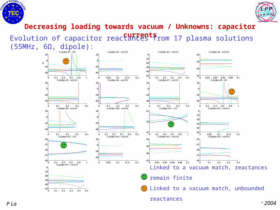
Decreasing loading towards vacuum / Unknowns: capacitor currents
Evolution of capacitor reactances from 17 plasma solutions (55MHz, 6Ω, dipole):
Linked to a vacuum match, reactances remain finite
Linked to a vacuum match, unbounded reactances

P Lamalle, A Messiaen et al ICRH CT matching satellite meeting , 23rd SOFT, Venice, 21 September 2004
Comments - open issues
• Practical path must always remain within capacitor range!
• Define parameter paths avoiding ‘collisions’ of solutions?
• Abandon real Z0 (see 2-strap study): may hopefully yield easier handling of the system (at least numerically).

P Lamalle, A Messiaen et al ICRH CT matching satellite meeting , 23rd SOFT, Venice, 21 September 2004
-2 0 2 4 6 8 10 12 14 16 18
-8
-6
-4
-2
0
2
4
6
8
Solution #2 - port #1
Illustration: constant reflection curves in cx. plane(purely resistive ELM perturbation)
0 2 4 6 8 10 12 14 16 18
-8
-6
-4
-2
0
2
4
6
8
Solution #2 - port #1
SWR=1.5
The ELM
Optimized settings
Re
Im
The ELM
Detuned settings
Re
Im
P Lamalle, A Messiaen et al ICRH CT matching satellite meeting , 23rd SOFT, Venice, 21 September 2004
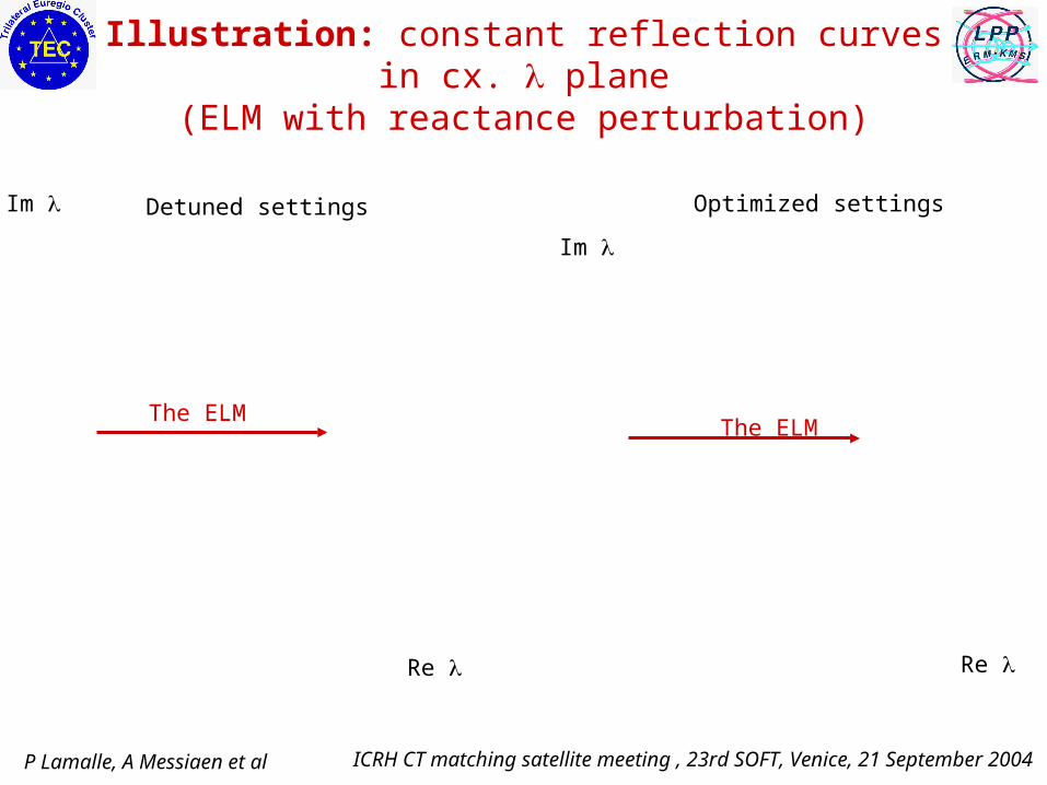
Illustration: constant reflection curves in cx. plane(ELM with reactance perturbation)
The ELM
Optimized settings
Re
Im
The ELM
Detuned settings
Re
Im