Embed Size (px)
Citation preview
P07441 Detailed Design Review Meeting Design Specifications 1. Capable of testing variable module length and width Design test stand mounting system to accommodate modules specified in the Engineering specifications. The optimal cooling area is large enough to accommodate the largest commercially available thermoelectric module, and will accommodate subsequent thermoelectric modules.
2. Capable of testing variable module thickness Design test stand mounting system to accommodate modules specified in the Engineering specifications. The clamping mechanism for the TEG is flexible enough to accommodate the height of any single-stage module. 3. Single Phase 120V Power Choose parts during design stage based on power demand to ensure power does not exceed breaker limit. Verify that the power consumption of primary and auxiliary components is well below the breaker limit. 4. Robustness: test stand can withstand max temperature Apply intense thermal load (hot side temperature 600 Celsius) via ANSYS, confirm with prolonged test at that temperature with a dummy thermal load (ceramic) 5. Record current Design LabVIEW system to accept current input, confirm with simulation data and test series on a dummy current load (ceramic). 6. Record voltage Design LabVIEW system to accept voltage input, confirm with simulation data and test series on a dummy current load (ceramic). 7. Modules can be compared to each other DAQ system outputs data in a format which allows the creation of IV curves for each module. 8. Modifiable ∆T, Thot, I, V Confirm that the temperature controller can change the power output of each heating element in addition to controlling the flow rate of the pump. 9. ∆T, Thot may be measured with a reasonable uncertainty Compare the FEA simulation of load with predicted temperature from the measured temperature gradient in heater block or dummy thermal load equipped with a surface thermocouple. Repeat experiment to determine the variation in measurement. 10. Provide heat flux for current modules Mount three thermocouples in parallel on the heating block and capture temperature information. Estimate the heat flux at the surface based on this information. 11. Provide heat flux for future modules Mount three thermocouples in parallel on the heating block and capture temperature information. Estimate the heat flux at the surface based on this information. Check against number indicated in engineering specification.

P07441 Detailed Design Review 12. Electrical power curves at different operating conditions Design LabVIEW to create power curves for each steady-state temperature achieved. Compare the measurements to published curves (where available) to confirm their accuracy. 13. System can test a reasonable number of thermal cycles Run twenty thermal cycles on a dummy thermal load within error tolerance. 14. Robustness: Electrical power components Choose components with appropriate lifetimes. Check for wear after tests are completed. 15. Robustness: structural Complete structural analysis on components at risk of failing from mechanical or thermal stresses. Inspect structural components between testing suites to ensure soundness. 16. Minimal time required to complete experiment FEA thermal simulation. Create system able to quickly heat and cool. Confirm with testing on cycle time. 17. Minimal setup Measure the time required to prepare for a particular test suite, and compare the recorded figure to the engineering specification. Confirm with testing on setup time. 18. Operators are shielded from electrical components All bear wires are isolated from human interaction while system is attached to power source. Design routing of wires carrying unsafe amount of electrical power such that the exposure is minimized. 19. Thermal isolation between hot surfaces and operator Design shielding for test stand. Test exterior temperature during entire thermal cycle. Design the system so that DAQ and test stand are separate entities. 20. Warning and hazard messages are mounted at appropriate locations Place warning signs at appropriate locations on test stand. Have a third party confirm the placement of safety messages. 21. DAQ system automatically conducts test once the system is setup. Design LabVIEW program to conduct tests automatically. Perform simulations to determine if the program works in the expected way. 22. Kill switches implemented in software and hardware Implement failure routines in LabVIEW which are automatically triggered when certain conditions are met. Have an easily accessible button on or near the test stand which terminates power to the heating side. The cooling side system should be powered from a different source to ensure operation while the heating side cools down.

P07441 Detailed Design Review 23. Test stand experiments are repeatable Conduct several experiments under the same operating conditions with different TEG’s of the same model number at different points in time. Compare the results from these experiments to confirm consistency. Contingency Plan: 4. Robustness: test stand can withstand max temperature Apply intense thermal load (hot side temperature 600 Celsius) via ANSYS, confirm with prolonged test at that temperature with a dummy thermal load (ceramic) Contingency: In case of failure, first examine analytical models that decrease the thickness of the plate in order to reduce maximum temperature around the heaters. If shortening the plate does not look viable, then look to a higher-temperature copper alloy, or metal (i.e. steel) to machine block out of. 8. Modifiable ∆T, Thot, I, V Confirm that the temperature controller can change the power output of each heating element in addition to the pump flow rate. Contingency: In case of failure, check to make sure that signal amplification is adequate. Otherwise, increment the flow rate manually. 9. ∆T, Thot may be measured with a reasonable uncertainty Compare the FEA simulation of load with predicted temperature from the measured temperature gradient in heater block or dummy thermal load equipped with a surface thermocouple. Repeat experiment to determine the variation in measurement. Contingency: In case of inaccurate measurements, embed a fine thermocouple in the heater block at the interface surface. 13. System can test a reasonable number of thermal cycles Run twenty thermal cycles on a dummy thermal load within error tolerance. Contingency: In case of failure examine replacing failed part with more robust part. 15. Robustness: structural Complete structural analysis on components at risk of failing from mechanical or thermal stresses Contingency: Re-design modular parts to be more robust. 16. Minimal time required to complete experiment FEA thermal simulation. Create system able to quickly heat and cool. Confirm with testing on cycle time. Contingency: Examine improving the thermal interface material or shortening the heater block.

P07441 Detailed Design Review 23. Test stand experiments are repeatable Conduct several experiments under the same operating conditions with different TEG’s of the same model number at different points in time. Compare the results from these experiments to confirm consistency. Contingency: If the repeatability is outside of thermoelectric specification errors, examine variability in the pressure mounting, or thermal interface material. If the variability is large due to either of the mounting issues, develop a more rigorous, fool-proof method of module mounting. The next facet to examine is the flatness of the heating block and cold plate. Additionally, the quality of the coolant, and the accuracy of the pump and fan can be examined to ensure steady, repeatable performance. This can be done by running the cooling system with a small thermal load and no thermoelectric. If the problem persists then the mounting issues can be ruled out as a source of variability and individual system components should be evaluated. The heater can be tested at low loads, stand alone with no cooling. Any individual component that appears to be the source of a large amount of variability should be re-designed. The modular nature of the system allows for relatively easy replacement. Enough copper and insulation has been purchased to make a second heating plate if necessary. Other components, like the cooling end can be purchased mostly “off-the-shelf”. Ambient conditions also may need to be checked (humidity especially for thermoelectrics) and possibly controlled.

DAQ BoardWater Tank
Pump
Cooling Plate
Heat Exchanger
T
TC4P-5
Computer/Lab View
P-19
P-20
P-30
Temperature Controller 2Power Controller 2
P-34
S-1S-2S-3
S-4
T
TC5
T
TC6
CV2CV2
S-5
S-6
P-35P-36S-7
S-8
Necessary?
CV3

Heating Block w/Heating
Elements
Cold Plate
TEG
Servo
Rheostat 1
TC1
TC4
CV1
DAQ & Control System Diagram
Temperature
Controller 1
Temperature
Controller 2
TC2
TC3
TC1
TC4
CV1
TC2
TC3
CV2
CV3
CV4
CV4
CV5
CV2
Inputs
Outputs
PCI Card Connector Block
CV5
Thermocouple Leads:
TC1 Thermocouple embedded in heating block
TC2 Thermocouple embedded in heating block
TC3 Thermocouple embedded in heating block
TC4 Thermocouple embedded in cold plate
TC5 Thermocouple mounted at inlet to cold plate
TC6 Thermocouple mounted at outlet of cold plate
Control Inputs:
CV1 Lead from current transducer
CV2 Control signal into Temperature Controller 2, which controls pump flow rate
CV3 Output signal from pump to DAQ
CV4 Input voltage into Servo controlling the rheostat
CV5 Control signal into Temperature Controller 1, which controls the hot side temperature
Selected Blocks:
Rheostat 1 Constant resistance; used as a safety mechanism
Rheostat 2 Variable resistance; used to produce IV curves at steady temperatures
Servo Control
Board
LabVIEW PCI Card
Voltage/Current
Transducer
Power
Controller 2
Power
Controller 1
Pump
Rheostat 2
TC5 TC6TC6
TC5
CV3

Week 6 Week 7 Week 8 Week 9 Week 10Week 5Week 4Week 3Week 2Week 1 Week 11
Engineering
Drawings
Final
Analysis
Final
Formal Eng. Specs.
Test Plan
Stage 2
Bill of Materials
Final
Detailed Design Review
LabVIEW
Backend
Stage 1
LabVIEW
Program
Stage 2
Contingency Plans
Stage 1
Contingency Plans
Final
Formal Eng. Specs.
Test Plan
Final
Satisfying Action
Items
Stage 1
BOM – Order
long lead time
items
Satisfying Action
Items
Final
Manufacturing
Plans
Stage 1
Manufacturing
Plans
Final
LabVIEW
Program
Stage 3
LabVIEW
Simulation Testing
Stage 1
LabVIEW
Simulation Testing
Final
Function and Perform
ance Review
BOM – Order all
necessary parts
Assembly (see
Google Docs)
Stage 1
Assembly (see
Google Docs)
Stage 2
Assembly (see
Google Docs)
Stage 3
Preliminary Module
Tests
Stage 1
Test Modules
Stage 2
Test Stand
Manual
Stage 1
Test Stand
Manual
Stage 2
Testing Procedure
Stage 1
Testing Procedure
Stage 2
Testing Procedure
Final
Test Stand
Manual
Stage 2
Technical Paper, Poster, W
ebsite Due
LabVIEW
Program
Final
Project Review
Test Modules
Stage 2
Validation &
Debugging
Stage 3
Technical Paper
Stage 1
Technical Paper
Stage 2
Technical Paper
Stage 3
Technical Paper
Final

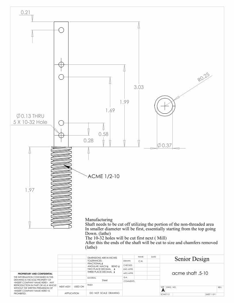
ManufacturingThis part can be hand drilled to get the proper hole.It will have a screw that will go through the acme shafta 4-40 is the designated screw size
2
DO NOT SCALE DRAWING
6473K760
345
1
UNLESS OTHERWISE SPECIFIED:
OF 1:2
REVDWG. NO.
ASIZE
TITLE:
Senior DesignNAME DATE
COMMENTS:
Q.A.
MFG APPR.
ENG APPR.
CHECKED
DRAWN
FINISH
MATERIAL
SCALE:
TOLERANCING PER:
INTERPRET GEOMETRIC
1SHEET PROHIBITED.
DIMENSIONS ARE IN INCHES
TOLERANCES:
THREE PLACE DECIMAL
APPLICATION
USED ONNEXT ASSY
PROPRIETARY AND CONFIDENTIAL
TWO PLACE DECIMAL
BEND ANGULAR: MACH
FRACTIONAL
THE INFORMATION CONTAINED IN THIS
DRAWING IS THE SOLE PROPERTY OF
<INSERT COMPANY NAME HERE>. ANY
REPRODUCTION IN PART OR AS A WHOLE
WITHOUT THE WRITTEN PERMISSION OF
<INSERT COMPANY NAME HERE> IS
1
0.06R
0.46
0.37
R0.25
1.99
0.58
0.28
1.69
3.03
5 X 10-32 Hole
1.97
0.13 THRU
0.21
ACME 1/2-10
ManufacturingShaft needs to be cut off utilizing the portion of the non-threaded areaIn smaller diameter will be first, essentially starting from the top going Down. (lathe)The 10-32 holes will be cut first next ( Mill)After this the ends of the shaft will be cut to size and chamfers removed(lathe)
TWO PLACE DECIMAL
acme shaft .5-10
Steel
Senior DesignC.H.
PROPRIETARY AND CONFIDENTIAL
SIZE DWG. NO.
AREV.
MATERIAL
FINISH
PROHIBITED.
COMMENTS:
<INSERT COMPANY NAME HERE> IS
WITHOUT THE WRITTEN PERMISSION OF
REPRODUCTION IN PART OR AS A WHOLE
1
Q.A.
MFG APPR.
ENG APPR.
CHECKED
DRAWN
DATENAME
OF 1SHEET
<INSERT COMPANY NAME HERE>. ANY
DRAWING IS THE SOLE PROPERTY OF
THE INFORMATION CONTAINED IN THIS
THREE PLACE DECIMAL
NEXT ASSY USED ON
APPLICATION DO NOT SCALE DRAWING
DIMENSIONS ARE IN INCHES
TOLERANCES:
FRACTIONAL
ANGULAR: MACH BEND
SCALE:1:2

0
8.05
9.7
5
10.5
0
0
0.75
7.30
0.7
5
1/2-20 UNF - 2B 0.75
4x 0.45 1.15
2
DO NOT SCALE DRAWING
Base Plate
345
1
C.H.
UNLESS OTHERWISE SPECIFIED:
OF 1:5
REVDWG. NO.
ASIZE
TITLE:
Senior DesignNAME DATE
COMMENTS:
Q.A.
MFG APPR.
ENG APPR.
CHECKED
DRAWN
Al 6061
FINISH
MATERIAL
SCALE:
TOLERANCING PER:
INTERPRET GEOMETRIC
1SHEET PROHIBITED.
DIMENSIONS ARE IN INCHES
TOLERANCES:
THREE PLACE DECIMAL
APPLICATION
USED ONNEXT ASSY
PROPRIETARY AND CONFIDENTIAL
TWO PLACE DECIMAL
BEND ANGULAR: MACH
FRACTIONAL
THE INFORMATION CONTAINED IN THIS
DRAWING IS THE SOLE PROPERTY OF
<INSERT COMPANY NAME HERE>. ANY
REPRODUCTION IN PART OR AS A WHOLE
WITHOUT THE WRITTEN PERMISSION OF
<INSERT COMPANY NAME HERE> IS
1
0.75
Manufacturing This part is from the aluminum 1X2 foot section cut to a 12X11 sectionTwo sides should be faced off for reference surfacesPart should be machined to length (mill)Part holes should be drilled and taped (mill)Finish process hand (removal of sharp edges)

0
1.00
5.00
6.00
0
1.500
1.50
2.00
4.00
4.50
6.00
0
1.50
3.00
4.50
6.00
Senior Design
Top Ceramic InsulationBecause the ceramic is constructed of 1 inch pieces2 will have to be machined together one slab wouldBe required for each layer, this may have to be machinedSlow first to get it to size. Once it is the correct size (mill)The hoses will be dilled slowerly followed by tapingOnce the hole part is machined it must be essential heat treated
1
DO NOT SCALE DRAWING
Bottom spring restraint
234
1
UNLESS OTHERWISE SPECIFIED:
OF 1:2
REVDWG. NO.
ASIZE
TITLE:
NAME DATE
COMMENTS:
Q.A.
MFG APPR.
ENG APPR.
CHECKED
DRAWN
CeramicFINISH
MATERIAL
SCALE:
TOLERANCING PER:
INTERPRET GEOMETRIC
1SHEET
5
THREE PLACE DECIMAL
DIMENSIONS ARE IN INCHES
TOLERANCES:
FRACTIONAL
ANGULAR: MACH BEND
TWO PLACE DECIMAL
C.H.
2.00
1/4-20 UNC - 2B 0.508x 0.20 1.00
x 2 THRU ALL0.20
1.254 X
10-32 UNF - 2B 0.384x 0.16 0.50

0
0.80
0.05
0.55
0.60
0.75
0.37
Flange shaft Conector
DO NOT SCALE DRAWING
123
1
C.H.
UNLESS OTHERWISE SPECIFIED:
OF 2:1
REVDWG. NO.
ASIZE
TITLE:
Senior DesignNAME DATE
COMMENTS:
Q.A.
MFG APPR.
ENG APPR.
CHECKED
DRAWN
ERROR!:Finish
ERROR!:MaterialFINISH
MATERIAL
SCALE:
TOLERANCING PER:
INTERPRET GEOMETRIC
1SHEET
45
PROHIBITED.
THREE PLACE DECIMAL
APPLICATION
USED ONNEXT ASSY
PROPRIETARY AND CONFIDENTIAL
TWO PLACE DECIMAL
BEND ANGULAR: MACH
FRACTIONAL
TOLERANCES:
DIMENSIONS ARE IN INCHES
THE INFORMATION CONTAINED IN THIS
DRAWING IS THE SOLE PROPERTY OF
<INSERT COMPANY NAME HERE>. ANY
REPRODUCTION IN PART OR AS A WHOLE
WITHOUT THE WRITTEN PERMISSION OF
<INSERT COMPANY NAME HERE> IS
2
10-32 Hole0.16
0.25
ManufacturingConstructed from the excess material of the main supports (2in)The part will be faced off to the correct length on each side (lathe)The holes where the shoulder bolts will be inserted should be drilled (mill)Next the outer features will be cut followed by the center hole (lathe)
0
1.00
5.00
6.00
0
3.50
4.00
0.500.50
0.20 THRU
1/4-20 UNC - 2B 0.502x 0.20 1.00
1.00
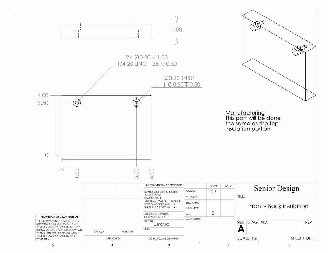
ManufacturingThis part will be donethe same as the top insulation portion
PROHIBITED.
5 4
DIMENSIONS ARE IN INCHES
TOLERANCING PER:
SCALE:
1
DO NOT SCALE DRAWING
Front - Back insulation
MATERIAL
INTERPRET GEOMETRIC
TOLERANCES:
1
FRACTIONAL
OF 1:2
REVDWG. NO.
ASIZE
TITLE:
Senior DesignNAME DATE
COMMENTS:
Q.A.
MFG APPR.
ENG APPR.
SHEET
ANGULAR: MACH
CHECKED
Ceramic
3
UNLESS OTHERWISE SPECIFIED:
C.H.
1
THREE PLACE DECIMAL
APPLICATION
USED ONNEXT ASSY
PROPRIETARY AND CONFIDENTIAL
TWO PLACE DECIMAL
BEND
2
FINISH
DRAWN
THE INFORMATION CONTAINED IN THIS
DRAWING IS THE SOLE PROPERTY OF
<INSERT COMPANY NAME HERE>. ANY
REPRODUCTION IN PART OR AS A WHOLE
WITHOUT THE WRITTEN PERMISSION OF
<INSERT COMPANY NAME HERE> IS
2

"
0.94"
2.50
3/8"
Crank Handle
6473K76Aluminum
NUMBERPART
http://www.mcmaster.com© 2006 McMaster-Carr Supply Company
Unless otherwise specified, dimensions are in inches. Information in this drawing is provided for reference only.
3.49"

0
2.00
4.00
6.00
0
3.00
6.00
0
0.75
6.00
3.00
1.01
05.25
2.001.68
0.51
Manufacturing This part should be cut to the general size of the block (mill)Once this is done the holes can be drilled from the same setup. The top portions should be taped first and the holes for the Cartage heater drilled last.The final step is the surface finish of the section directly in Contact with the thermal electric
This drawing is subject to change dueto the change in electrical heaters
1/4-20 UNC - 2B 0.502x 0.20 0.65
3 X 0.25
2 X 0.04
.001
1
C.H.
DO NOT SCALE DRAWING
Heating Block
UNLESS OTHERWISE SPECIFIED:
SCALE1: 3
DWG. NO.
ASIZE
TITLE:
NAME DATE
COMMENTS:
Q.A.
MFG APPR.
ENG APPR.
CHECKED
DRAWN
CopperFINISH
2
INTERPRET GEOMETRIC
MATERIAL
345
THREE PLACE DECIMAL
TOLERANCING PER:
DIMENSIONS ARE IN INCHES
TOLERANCES:
FRACTIONAL
ANGULAR: MACH BEND
TWO PLACE DECIMAL
Senior Design

9.65
10
.85
1/4 Threaded
0.75
0.25
5.004.75
10-32 Thr
0.15
The ends will be cut to the proper outer diameter of a ¼ -20 thread (lathe)
Structure Support Shafts
The part will then be threadedFinish process to make sure it screws in tightly to the base and top
Manufacturing11 in sections will be cut form the main 2 foot stock (band saw)Both sides of the cut section will be faced off (lathe)
needs to be threaded from the bottom upThread lenght should be up to 3.4 inchesHowever this may need to be ajusted
Senior Design
DO NOT SCALE DRAWING
UNLESS OTHERWISE SPECIFIED:
Main support shafts
1:5
REVDWG. NO.
ASIZE
TITLE:
NAME DATE
COMMENTS:
Q.A.
MFG APPR.
ENG APPR.
CHECKED
DRAWN
SteelFINISH
MATERIAL
SCALE:
TOLERANCING PER:
INTERPRET GEOMETRIC
12345
THREE PLACE DECIMAL
DIMENSIONS ARE IN INCHES
TOLERANCES:
FRACTIONAL
ANGULAR: MACH BEND
TWO PLACE DECIMAL
C.H.

CHECKED
DRAWN
ENG APPR.
MFG APPR.
Q.A.
5 4 1
Senior Design
Pressure Concept
SHEET 1
UNLESS OTHERWISE SPECIFIED:
SCALE: 1 OF 1:5
REVDWG. NO.
ASIZE
TITLE:
3 2
THREE PLACE DECIMAL
COMMENTS:
DATENAME
DIMENSIONS ARE IN INCHES
TOLERANCES:
FRACTIONAL
ANGULAR: MACH BEND
TWO PLACE DECIMAL
C.H.
17
18
1910
7
1215
11
20
8
5
14
26
1632421
23
27
22
9
4
Part discripton with numbers indicate McMaster specific part93615K16
Materials extimate from MetalsDepot.com Ultra-High Temperature Moldable Sheets
ITEMNO. PART Discription Cost
EachQTY.
1 Base Plate 86 12 cooling plate 350 13 TE 189 14 Top spring mount 50 1
5 Compressing Spring9588K21 7 4
6 Main support shafts 22 47 Top Plate 75 1
8 Nut and Flange95072A109
70 1
9 acme shaft .5-10 0 110 Bushing 2872T2 4 211 MSHXNUT 0.250-20-S-C 5 412 MSHXNUT 0.138-40-S-C 0 313 Bottom spring restraint 50 114 Flange shaft Conector 0 215 Al crank Handle 6473K76 23 116 7/8 Standard Connector 217 Aligning shaft 0 4
18 IN-HHMS0.138-40x0.75x0.75-C 0 2
19IN-HHMS0.138-40x1.25x1-C 0 1
20HX-SHCS0.25-20x1.25x1.25-N 5 4
21 Heating Block 475 1
22HX-SHCS0.25-20x2.25x1.25-N 3 2
23 pipe 224 Side insulation 225 Front - Back insulation 226 MSHXNUT 0.138-32-S-C 4
27HX-SHCS0.25-20x0.875x0.875-N 8

9/32" 3/16"1/2"
5/32"
1/8"
.138
#6-32 Thread
94045A529Precision Shoulder Screw
Type 18-8 Stainless Steel Phillips
Unless otherwise specified, dimensions are in inches. Information in this drawing is provided for reference only.
http://www.mcmaster.com(c) 2003 McMaster-Carr Supply Company
NUMBERPART

0
2.00
6.00
8.00
0
4.00
3.50
0.20 1.00
1/4-20 UNC - 2B 0.50
2x
2 X 0.50
1.00
C.H.
DO NOT SCALE DRAWING
Side insulation
123
1
UNLESS OTHERWISE SPECIFIED:
OF 1:1
REVDWG. NO.
ASIZE
TITLE:
Senior DesignNAME DATE
COMMENTS:
Q.A.
MFG APPR.
ENG APPR.
CHECKED
DRAWN
Ceramic
FINISH
MATERIAL
SCALE:
TOLERANCING PER:
INTERPRET GEOMETRIC
1SHEET
45
PROHIBITED.
THREE PLACE DECIMAL
APPLICATION
USED ONNEXT ASSY
PROPRIETARY AND CONFIDENTIAL
TWO PLACE DECIMAL
BEND ANGULAR: MACH
FRACTIONAL
TOLERANCES:
DIMENSIONS ARE IN INCHES
THE INFORMATION CONTAINED IN THIS
DRAWING IS THE SOLE PROPERTY OF
<INSERT COMPANY NAME HERE>. ANY
REPRODUCTION IN PART OR AS A WHOLE
WITHOUT THE WRITTEN PERMISSION OF
<INSERT COMPANY NAME HERE> IS
2
Manufacturing (mill)Manufacturing of this will be the same as The top portion of the ceramic isolationNote there are two of these peaces whcihmust come from a single slab

Fits 1 1/4"Hole Size
Fits 5/8"Rod Size
1 1/2"
.286WireWidth
.200Wire
Thickness
9588K21Die Spring
Chrome-Silicon Steel
Unless otherwise specified, dimensions are in inches. Information in this drawing is provided for reference only.
http://www.mcmaster.com(c) 2003 McMaster-Carr Supply Company
NUMBERPART

00.75
3.75
5.25
6.75
9.75
10.50
00.75
2.53
4.03
5.53
7.308.05
ManufacturingThis is from a 1 square foot steel sectionThis is purely millPart should be cut to length for over all dimensionsHoles are drilled then tapedFinal part is removal of chamfers
0.75 0.02
0.37 THRU
2
DO NOT SCALE DRAWING
Top Plate
C.H.
UNLESS OTHERWISE SPECIFIED:
3
1:5
REVDWG. NO.
ASIZE
TITLE:
Senior DesignNAME DATE
COMMENTS:
Q.A.
MFG APPR.
ENG APPR.
CHECKED
DRAWN
Steel
FINISH
MATERIAL
SCALE:
TOLERANCING PER:
INTERPRET GEOMETRIC
45
PROHIBITED.
DIMENSIONS ARE IN INCHES
TOLERANCES:
THREE PLACE DECIMAL
APPLICATION
USED ONNEXT ASSY
PROPRIETARY AND CONFIDENTIAL
TWO PLACE DECIMAL
BEND ANGULAR: MACH
FRACTIONAL
THE INFORMATION CONTAINED IN THIS
DRAWING IS THE SOLE PROPERTY OF
<INSERT COMPANY NAME HERE>. ANY
REPRODUCTION IN PART OR AS A WHOLE
WITHOUT THE WRITTEN PERMISSION OF
<INSERT COMPANY NAME HERE> IS
1
THRU ALL4 0.45
THRU ALL0.37
x
4x 0.16 THRU ALL
0.50

0
1.00
3.55
2.50
3.55
4.00
5.00
0
1.00
1.46
5.00
2.50
4.00
1.46
0
2.50
1.00
4.00
1.46
4.00
5.00 0
2.50
3.55
1.001.46
3.55
5.00
Senior Design
Top Spring MountManufacturingThe top spring mount is a peace form the 1X2 foot section (mill)It will cut with .5 inch of leeway. This is purely a milling processOnce the edges are defined the holes can be drilled and taped
2 1
DO NOT SCALE DRAWING
Top spring mount
3
TOLERANCES:
1:2
REVDWG. NO.
ASIZE
TITLE:
NAME DATE
COMMENTS:
Q.A.
MFG APPR.
ENG APPR.
CHECKED
DRAWN
AL 6061FINISH
UNLESS OTHERWISE SPECIFIED:
SCALE:
MATERIAL
45
PROHIBITED.
DIMENSIONS ARE IN INCHES
TOLERANCING PER:PROPRIETARY AND CONFIDENTIAL
THREE PLACE DECIMAL
APPLICATION
USED ONNEXT ASSY
TWO PLACE DECIMAL
BEND ANGULAR: MACH
FRACTIONAL
INTERPRET GEOMETRIC
THE INFORMATION CONTAINED IN THIS
DRAWING IS THE SOLE PROPERTY OF
<INSERT COMPANY NAME HERE>. ANY
REPRODUCTION IN PART OR AS A WHOLE
WITHOUT THE WRITTEN PERMISSION OF
<INSERT COMPANY NAME HERE> IS
C.H.
0.75
0.53
1.25
THRU
3 X
0.20x THRU ALL1/4-20 UNC - 2BTHRU ALL
4
1.28 0.130.16 THRU
4 0.20 THRU ALLx
THRU ALL
1/4-20 UNC - 2BTHRU ALL
4x 0.16
0.53