Embed Size (px)
Citation preview
Freescale SemiconductorP1010RDB-PB Quick Start Guide
© 2013 Freescale Semiconductor, Inc. All rights reserved.
1 Introduction to P1010RDB-PBThis quick start guide applies to boards with assembly revision 700-27904 Rev X4. See the top side of the board to get the revision number.
This document describes P1010RDB-PB and its related hardware kit. It also explains and verifies the basic board operations in a step-by-step format.
This document shows settings for switches, connectors, jumpers, push buttons, and LEDs, and you can find instructions for connecting peripheral devices.
Document Number: P1010RDBPBQSRev. 0, 10/2013
Contents1. Introduction to P1010RDB-PB . . . . . . . . . . . . . . . . . . 12. Getting Started . . . . . . . . . . . . . . . . . . . . . . . . . . . . . . 2
P1010RDB-PB Quick Start Guide
P1010RDB-PB Quick Start Guide, Rev. 0
2 Freescale Semiconductor
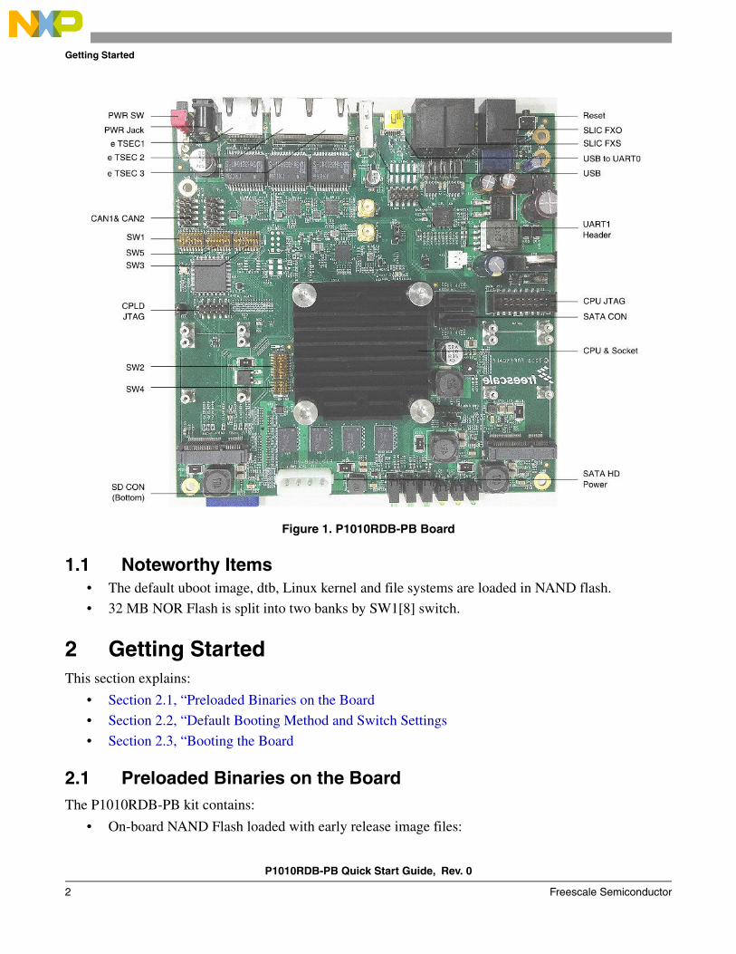
Getting Started
Figure 1. P1010RDB-PB Board
1.1 Noteworthy Items• The default uboot image, dtb, Linux kernel and file systems are loaded in NAND flash.
• 32 MB NOR Flash is split into two banks by SW1[8] switch.
2 Getting StartedThis section explains:
• Section 2.1, “Preloaded Binaries on the Board
• Section 2.2, “Default Booting Method and Switch Settings
• Section 2.3, “Booting the Board
2.1 Preloaded Binaries on the BoardThe P1010RDB-PB kit contains:
• On-board NAND Flash loaded with early release image files:
P1010RDB-PB Quick Start Guide, Rev. 0
Freescale Semiconductor 3
Getting Started
u-boot-nand.bin
p1010.dtb
uImage.p1010
fsl-image-core-p1010rdb-20130615092723.rootfs.ext2.gz
• On-board NOR Flash and SPI flash are both loaded a bootable image, too.
2.2 Default Booting Method and Switch SettingsThe default booting method and switch settings are:
• The default booting setting is NAND Flash.
• The default settings result in the following frequency settings:
CPU = 1000 MHz, CCB = 400 MHz and DDR = 800MT/s data rate.
2.3 Booting the BoardFollow the given steps to boot a target board:
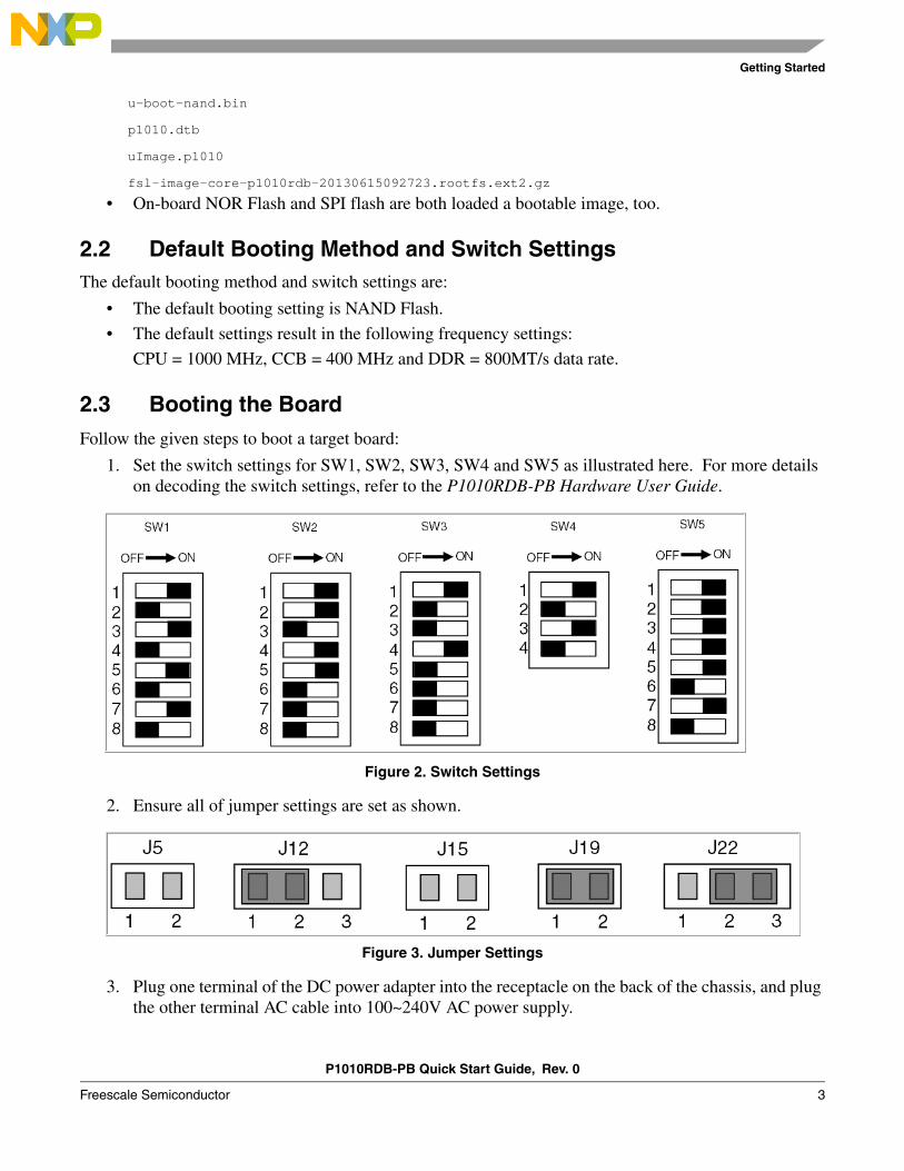
1. Set the switch settings for SW1, SW2, SW3, SW4 and SW5 as illustrated here. For more details on decoding the switch settings, refer to the P1010RDB-PB Hardware User Guide.
Figure 2. Switch Settings
2. Ensure all of jumper settings are set as shown.
Figure 3. Jumper Settings
3. Plug one terminal of the DC power adapter into the receptacle on the back of the chassis, and plug the other terminal AC cable into 100~240V AC power supply.
P1010RDB-PB Quick Start Guide, Rev. 0
4 Freescale Semiconductor
Getting Started
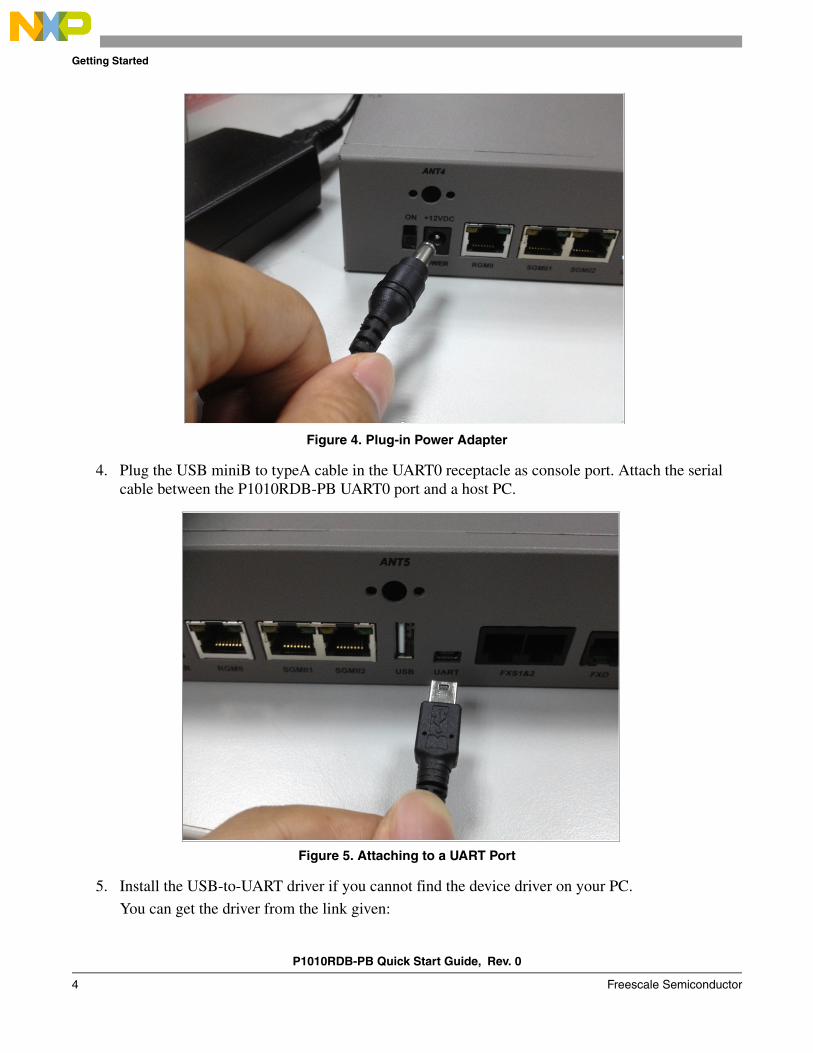
Figure 4. Plug-in Power Adapter
4. Plug the USB miniB to typeA cable in the UART0 receptacle as console port. Attach the serial cable between the P1010RDB-PB UART0 port and a host PC.
Figure 5. Attaching to a UART Port
5. Install the USB-to-UART driver if you cannot find the device driver on your PC.
You can get the driver from the link given:
P1010RDB-PB Quick Start Guide, Rev. 0
Freescale Semiconductor 5
Getting Started
http://www.silabs.com/products/mcu/pages/usbtouartbridgevcpdrivers.aspx
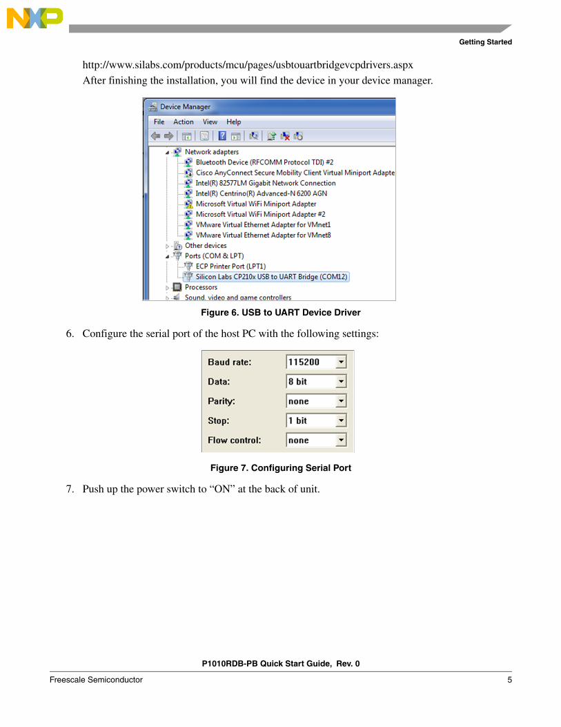
After finishing the installation, you will find the device in your device manager.
Figure 6. USB to UART Device Driver
6. Configure the serial port of the host PC with the following settings:
Figure 7. Configuring Serial Port
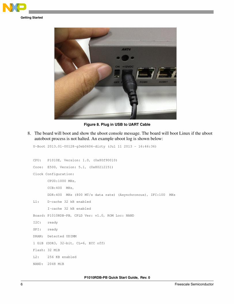
7. Push up the power switch to “ON” at the back of unit.
P1010RDB-PB Quick Start Guide, Rev. 0
6 Freescale Semiconductor
Getting Started
Figure 8. Plug in USB to UART Cable
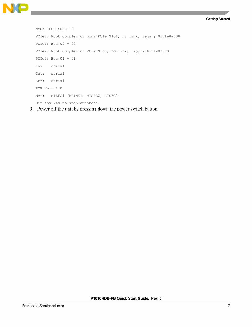
8. The board will boot and show the uboot console message. The board will boot Linux if the uboot autoboot process is not halted. An example uboot log is shown below:
U-Boot 2013.01-00128-g3eb0606-dirty (Jul 11 2013 - 16:46:36)
CPU: P1010E, Version: 1.0, (0x80f90010)
Core: E500, Version: 5.1, (0x80212151)
Clock Configuration:
CPU0:1000 MHz,
CCB:400 MHz,
DDR:400 MHz (800 MT/s data rate) (Asynchronous), IFC:100 MHz
L1: D-cache 32 kB enabled
I-cache 32 kB enabled
Board: P1010RDB-PB, CPLD Ver: v1.0, ROM Loc: NAND
I2C: ready
SPI: ready
DRAM: Detected UDIMM
1 GiB (DDR3, 32-bit, CL=6, ECC off)
Flash: 32 MiB
L2: 256 KB enabled
NAND: 2048 MiB
P1010RDB-PB Quick Start Guide, Rev. 0
Freescale Semiconductor 7
Getting Started
MMC: FSL_SDHC: 0
PCIe1: Root Complex of mini PCIe Slot, no link, regs @ 0xffe0a000
PCIe1: Bus 00 - 00
PCIe2: Root Complex of PCIe Slot, no link, regs @ 0xffe09000
PCIe2: Bus 01 - 01
In: serial
Out: serial
Err: serial
PCB Ver: 1.0
Net: eTSEC1 [PRIME], eTSEC2, eTSEC3
Hit any key to stop autoboot:
9. Power off the unit by pressing down the power switch button.
Document Number: P1010RDBPBQSRev. 0
10/2013
Information in this document is provided solely to enable system and software
implementers to use Freescale products. There are no express or implied copyright
licenses granted hereunder to design or fabricate any integrated circuits based on the
information in this document.
Freescale reserves the right to make changes without further notice to any products
herein. Freescale makes no warranty, representation, or guarantee regarding the
suitability of its products for any particular purpose, nor does Freescale assume any
liability arising out of the application or use of any product or circuit, and specifically
disclaims any and all liability, including without limitation consequential or incidental
damages. “Typical” parameters that may be provided in Freescale data sheets and/or
specifications can and do vary in different applications, and actual performance may vary
over time. All operating parameters, including “typicals,” must be validated for each
customer application by customer’s technical experts. Freescale does not convey any
license under its patent rights nor the rights of others. Freescale sells products pursuant
to standard terms and conditions of sale, which can be found at the following address:
freescale.com/SalesTermsandConditions
How to Reach Us:
Home Page: freescale.com
Web Support: freescale.com/support
Freescale, the Freescale logo, AltiVec, C-5, CodeTest, CodeWarrior, ColdFire, C-Ware,
Energy Efficient Solutions logo, Kinetis, mobileGT, PowerQUICC, Processor Expert,
QorIQ, Qorivva, StarCore, Symphony, and VortiQa are trademarks of Freescale
Semiconductor, Inc., Reg. U.S. Pat. & Tm. Off. Airfast, BeeKit, BeeStack, ColdFire+,
CoreNet, Flexis, MagniV, MXC, Platform in a Package, QorIQ Qonverge, QUICC Engine,
Ready Play, SafeAssure, SMARTMOS, TurboLink, Vybrid, and Xtrinsic are trademarks of
Freescale Semiconductor, Inc. All other product or service names are the property of
their respective owners.
© 2013 Freescale Semiconductor, Inc.