Embed Size (px)
Citation preview
Province of British Columbia Ministry of Transportation & Infrastructure
P6 (TS2 Type1) Drawing Guide Electrical Engineering Centre
MoTI P6 (TS2 Type 1) Controller Drawing Guidelines
2
Introduction
This document provides the basic guidelines for modifying the Ministry of Transportation and Infrastructure P6 (TS2 Type 1) Traffic Controller Cabinet drawings and is supplemental to the MoTI, Traffic Controller Design Manual. The guidelines in this document provide enough information to modify the P6 (TS2 Type 1) AutoCAD template drawings to reflect a typical intersection configuration based on the location’s Site Plans, Signal Timing Sheet (STS), Traffic Engineering Checklist (TEC) and Loop Assignment Sheet (LAS).
Title Block
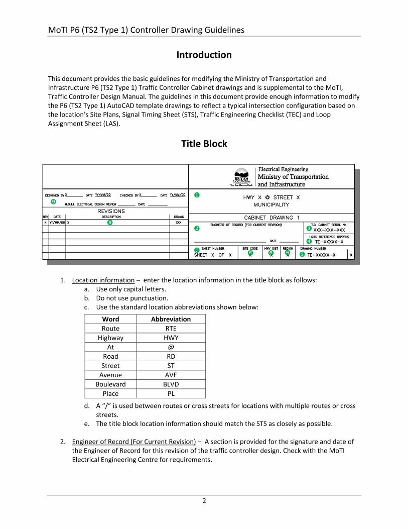
1. Location information – enter the location information in the title block as follows: a. Use only capital letters. b. Do not use punctuation. c. Use the standard location abbreviations shown below:
d. A “/” is used between routes or cross streets for locations with multiple routes or cross streets.
e. The title block location information should match the STS as closely as possible.
2. Engineer of Record (For Current Revision) – A section is provided for the signature and date of the Engineer of Record for this revision of the traffic controller design. Check with the MoTI Electrical Engineering Centre for requirements.
Word Abbreviation
Route RTE
Highway HWY
At @
Road RD
Street ST
Avenue AVE
Boulevard BLVD
Place PL
MoTI P6 (TS2 Type 1) Controller Drawing Guidelines
3
3. Traffic Controller Assembly (TCA) Serial Number – locate the serial number for the TCA to be modified and enter it in this field.
4. 1:250 Scale Reference – TCA drawings may be included in the complete electrical drawings series which would include site plans, elevations, other schematics, etc. If this is the case then item will be the drawings number within the series and item will be the 1:250 drawing that was used during the TCA design stages. The 1:250 scale drawing is typically where to find information on loops and intersection configuration. If the TCA drawings are not included in the complete electrical drawing series then item &will use the same number.
5. Drawing Number and Sheet Number – If the TCA drawings are being included in the complete electrical drawing series, a TE series number and a sheet number within that series will be provided by MoTI Electrical Engineering. If the controller design is not part of the complete series enter the same TE number as in item .
6. Site Code, Hwy Dist, and Region – Enter this information if known, otherwise leave it blank
7. Sheet Number – If the TCA drawings are to be part of a complete drawing series the sheet numbering will be provided by MoTI Electrical Engineering. If the TCA drawings are stand alone, the Cabinet Drawing 1 will be sheet 1 of 2 and Cabinet Drawing 2 will be sheet 2 of 2.
8. Revisions – Enter a brief description of scope of changes to the TCA drawings, include the Rev. letter of the site plan drawings referenced for the changes.
9. Enter the Designers name and date of latest revision. If required, indicate the name and date of the person who checked the drawings.
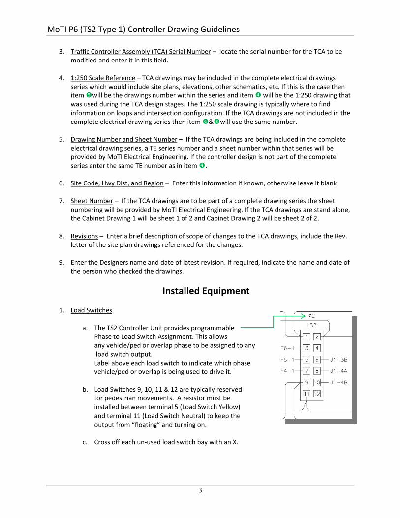
Installed Equipment 1. Load Switches
a. The TS2 Controller Unit provides programmable
Phase to Load Switch Assignment. This allows any vehicle/ped or overlap phase to be assigned to any load switch output. Label above each load switch to indicate which phase vehicle/ped or overlap is being used to drive it.
b. Load Switches 9, 10, 11 & 12 are typically reserved for pedestrian movements. A resistor must be installed between terminal 5 (Load Switch Yellow) and terminal 11 (Load Switch Neutral) to keep the output from “floating” and turning on.
c. Cross off each un-used load switch bay with an X.
MoTI P6 (TS2 Type 1) Controller Drawing Guidelines
4
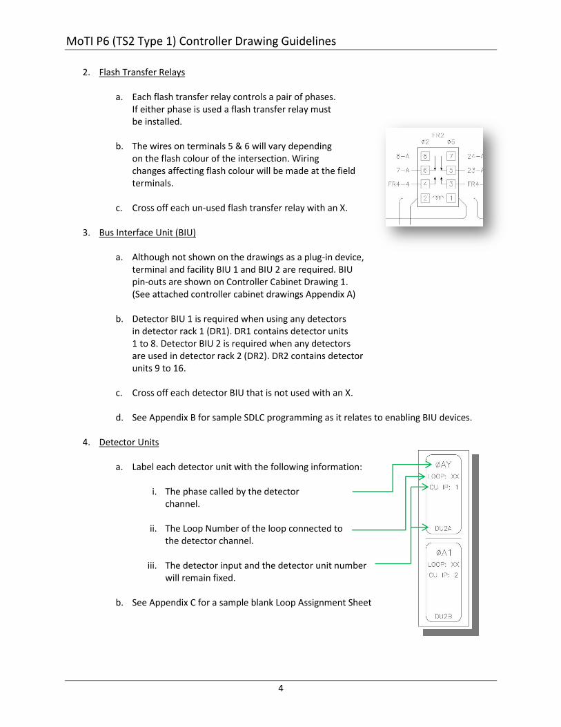
2. Flash Transfer Relays
a. Each flash transfer relay controls a pair of phases. If either phase is used a flash transfer relay must be installed.
b. The wires on terminals 5 & 6 will vary depending on the flash colour of the intersection. Wiring changes affecting flash colour will be made at the field terminals.
c. Cross off each un-used flash transfer relay with an X.
3. Bus Interface Unit (BIU)
a. Although not shown on the drawings as a plug-in device, terminal and facility BIU 1 and BIU 2 are required. BIU pin-outs are shown on Controller Cabinet Drawing 1. (See attached controller cabinet drawings Appendix A)
b. Detector BIU 1 is required when using any detectors in detector rack 1 (DR1). DR1 contains detector units 1 to 8. Detector BIU 2 is required when any detectors are used in detector rack 2 (DR2). DR2 contains detector units 9 to 16.
c. Cross off each detector BIU that is not used with an X.
d. See Appendix B for sample SDLC programming as it relates to enabling BIU devices.
4. Detector Units
a. Label each detector unit with the following information:
i. The phase called by the detector channel.
ii. The Loop Number of the loop connected to the detector channel.
iii. The detector input and the detector unit number will remain fixed.
b. See Appendix C for a sample blank Loop Assignment Sheet
MoTI P6 (TS2 Type 1) Controller Drawing Guidelines
5
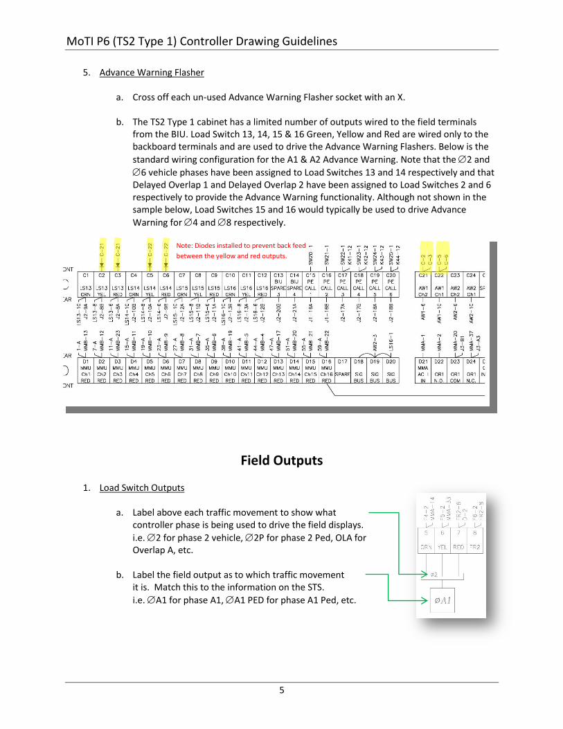
5. Advance Warning Flasher
a. Cross off each un-used Advance Warning Flasher socket with an X.
b. The TS2 Type 1 cabinet has a limited number of outputs wired to the field terminals from the BIU. Load Switch 13, 14, 15 & 16 Green, Yellow and Red are wired only to the backboard terminals and are used to drive the Advance Warning Flashers. Below is the
standard wiring configuration for the A1 & A2 Advance Warning. Note that the 2 and
6 vehicle phases have been assigned to Load Switches 13 and 14 respectively and that Delayed Overlap 1 and Delayed Overlap 2 have been assigned to Load Switches 2 and 6 respectively to provide the Advance Warning functionality. Although not shown in the sample below, Load Switches 15 and 16 would typically be used to drive Advance
Warning for 4 and 8 respectively.
Field Outputs
1. Load Switch Outputs
a. Label above each traffic movement to show what
controller phase is being used to drive the field displays.
i.e. 2 for phase 2 vehicle, 2P for phase 2 Ped, OLA for Overlap A, etc.
b. Label the field output as to which traffic movement it is. Match this to the information on the STS.
i.e. A1 for phase A1, A1 PED for phase A1 Ped, etc.
Note: Diodes installed to prevent back feed
between the yellow and red outputs.
MoTI P6 (TS2 Type 1) Controller Drawing Guidelines
6
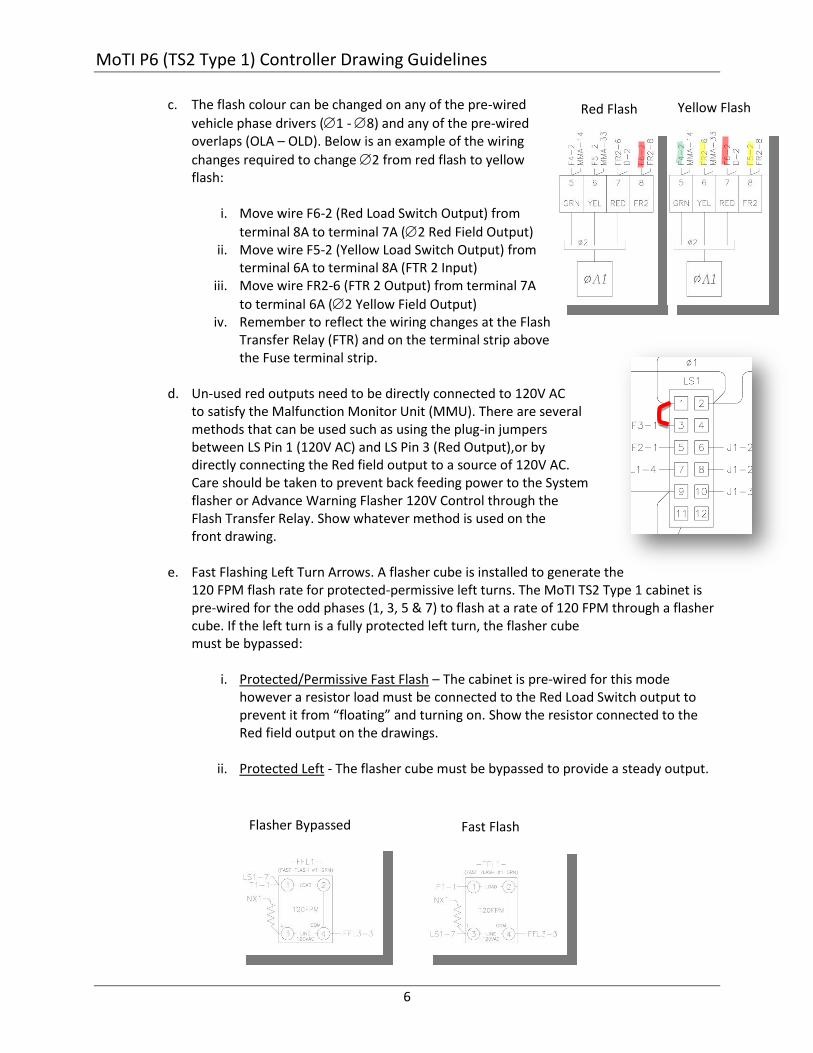
c. The flash colour can be changed on any of the pre-wired
vehicle phase drivers (1 - 8) and any of the pre-wired overlaps (OLA – OLD). Below is an example of the wiring
changes required to change 2 from red flash to yellow flash:
i. Move wire F6-2 (Red Load Switch Output) from
terminal 8A to terminal 7A (2 Red Field Output) ii. Move wire F5-2 (Yellow Load Switch Output) from
terminal 6A to terminal 8A (FTR 2 Input) iii. Move wire FR2-6 (FTR 2 Output) from terminal 7A
to terminal 6A (2 Yellow Field Output) iv. Remember to reflect the wiring changes at the Flash
Transfer Relay (FTR) and on the terminal strip above the Fuse terminal strip.
d. Un-used red outputs need to be directly connected to 120V AC to satisfy the Malfunction Monitor Unit (MMU). There are several methods that can be used such as using the plug-in jumpers between LS Pin 1 (120V AC) and LS Pin 3 (Red Output),or by directly connecting the Red field output to a source of 120V AC. Care should be taken to prevent back feeding power to the System flasher or Advance Warning Flasher 120V Control through the Flash Transfer Relay. Show whatever method is used on the front drawing.
e. Fast Flashing Left Turn Arrows. A flasher cube is installed to generate the 120 FPM flash rate for protected-permissive left turns. The MoTI TS2 Type 1 cabinet is pre-wired for the odd phases (1, 3, 5 & 7) to flash at a rate of 120 FPM through a flasher cube. If the left turn is a fully protected left turn, the flasher cube must be bypassed:
i. Protected/Permissive Fast Flash – The cabinet is pre-wired for this mode however a resistor load must be connected to the Red Load Switch output to prevent it from “floating” and turning on. Show the resistor connected to the Red field output on the drawings.
ii. Protected Left - The flasher cube must be bypassed to provide a steady output.
Red Flash Yellow Flash
Fast Flash Flasher Bypassed
MoTI P6 (TS2 Type 1) Controller Drawing Guidelines
7
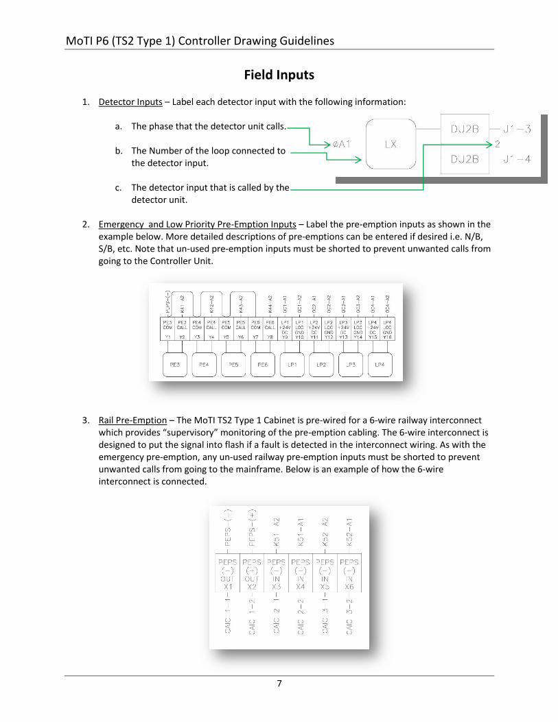
Field Inputs
1. Detector Inputs – Label each detector input with the following information:
a. The phase that the detector unit calls.
b. The Number of the loop connected to
the detector input.
c. The detector input that is called by the detector unit.
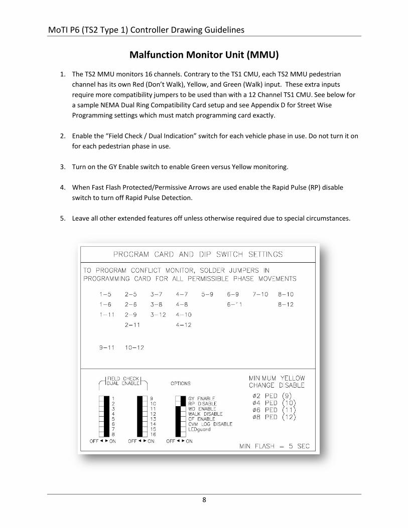
2. Emergency and Low Priority Pre-Emption Inputs – Label the pre-emption inputs as shown in the example below. More detailed descriptions of pre-emptions can be entered if desired i.e. N/B, S/B, etc. Note that un-used pre-emption inputs must be shorted to prevent unwanted calls from going to the Controller Unit.
3. Rail Pre-Emption – The MoTI TS2 Type 1 Cabinet is pre-wired for a 6-wire railway interconnect which provides “supervisory” monitoring of the pre-emption cabling. The 6-wire interconnect is designed to put the signal into flash if a fault is detected in the interconnect wiring. As with the emergency pre-emption, any un-used railway pre-emption inputs must be shorted to prevent unwanted calls from going to the mainframe. Below is an example of how the 6-wire interconnect is connected.
MoTI P6 (TS2 Type 1) Controller Drawing Guidelines
8
Malfunction Monitor Unit (MMU)
1. The TS2 MMU monitors 16 channels. Contrary to the TS1 CMU, each TS2 MMU pedestrian
channel has its own Red (Don’t Walk), Yellow, and Green (Walk) input. These extra inputs
require more compatibility jumpers to be used than with a 12 Channel TS1 CMU. See below for
a sample NEMA Dual Ring Compatibility Card setup and see Appendix D for Street Wise
Programming settings which must match programming card exactly.
2. Enable the “Field Check / Dual Indication” switch for each vehicle phase in use. Do not turn it on
for each pedestrian phase in use.
3. Turn on the GY Enable switch to enable Green versus Yellow monitoring.
4. When Fast Flash Protected/Permissive Arrows are used enable the Rapid Pulse (RP) disable
switch to turn off Rapid Pulse Detection.
5. Leave all other extended features off unless otherwise required due to special circumstances.
MoTI P6 (TS2 Type 1) Controller Drawing Guidelines
9
APPENDIX A
MoTI TS2 CONTROLLER DRAWINGS
MoTI P6 (TS2 Type 1) Controller Drawing Guidelines
10
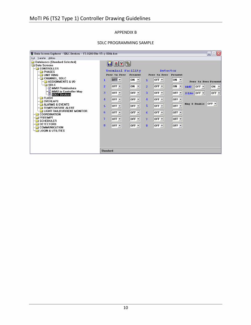
APPENDIX B
SDLC PROGRAMMING SAMPLE
MoTI P6 (TS2 Type 1) Controller Drawing Guidelines
11
APPENDIX C
SAMPLE LOOP ASSIGNMENT SHEET (BLANK)
MoTI P6 (TS2 Type 1) Controller Drawing Guidelines
12
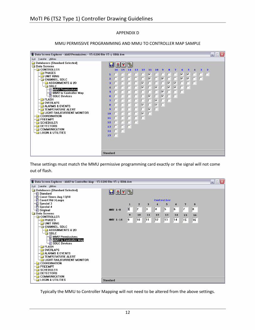
APPENDIX D
MMU PERMISSIVE PROGRAMMING AND MMU TO CONTROLLER MAP SAMPLE
These settings must match the MMU permissive programming card exactly or the signal will not come
out of flash.
Typically the MMU to Controller Mapping will not need to be altered from the above settings.