Embed Size (px)
Citation preview
^ P A C I F I C O R P ^•TRANSMISSION
Large Generator Interconnection Facilities Study Report
Final
C ompleted for
("Interconnection Customer") Q0708
Proposed Point of Interconnection
Shirley Basin substation at 230 kV
March 7, 2016
^ P A C I F I C O R P . T R A N S M I S S I O N
^ DRAFT Facilities Study Report
T A B L E O F C O N T E N T S
1.() D E S C R I P T I O N or T H E P R O J E C T I
2.0 S T U D Y SCOPE, A N D O B J E C T I V E S I
3.0 T Y P E O F I N T E R C O N N E C T I O N S E R V I C E 1
4.0 S T U D Y A S S U M P T I O N S 1
5.0 P R O P O S E D P O I N T O F I N T E R C O N N E C T I O N 2
6.0 S C O P E O F W O R K 4
6.1 Generating Facility Modifications 4 6.1.1 I N T E R C O N N E C T I O N C U S T O M E R T O B E R E S P O N S I B L E F O R 4
6.1.2 T R A N S M I S S I O N P R O V I D E R T O B E R E S P O N S I B L E F O R 6
6.2 Tic Line Requirements 7 6.2.1 I N T E R C O N N E C T I O N C U S T O M E R T O B E R E S P O N S I B L E F O R 7
6.2.2 T R A N S M I S S I O N P R O V I D E R T O B E R E S P O N S I B L E F O R 8
6.3 Point of Interconnection 9 6.3.1 I N T E R C O N N E C T I O N C U S T O M E R T O B E R E S P O N S I B L E F O R 9
6.3.2 T R A N S M I S S I O N P R O V I D E R T O B E R E S P O N S I B L E F O R 9
6.4 Other 10 6.4.1 I N T E R C O N N E C T I O N C U S T O M E R T O B E R E S P O N S I B L E F O R 10
6.4.2 T R A N S M I S S I O N P R O V I D E R T O B E R E S P O N S I B L E F O R 10
7.0 C O S T E S T I M A T E (+/- 20%) 11
8.0 S C H E D U L E 13
9.0 P A R T I C I P A T I O N B Y A F F E C T E D S Y S T E M S 13
10.0 A P P E N D I C E S 14
10.1 A P P E N D I X 1: H I G H E R P R I O R I T Y R E Q U E S T 15
10.2 A P P E N D I X 2: P R O P E R T Y R E Q U I R E M E N T S 16
March 7.2017
/ Q0708 Page i CONFIDENTIAL / FINAL
PACIFICORP T R A N S M I S S I O N
DRAFT Facilities Study Report
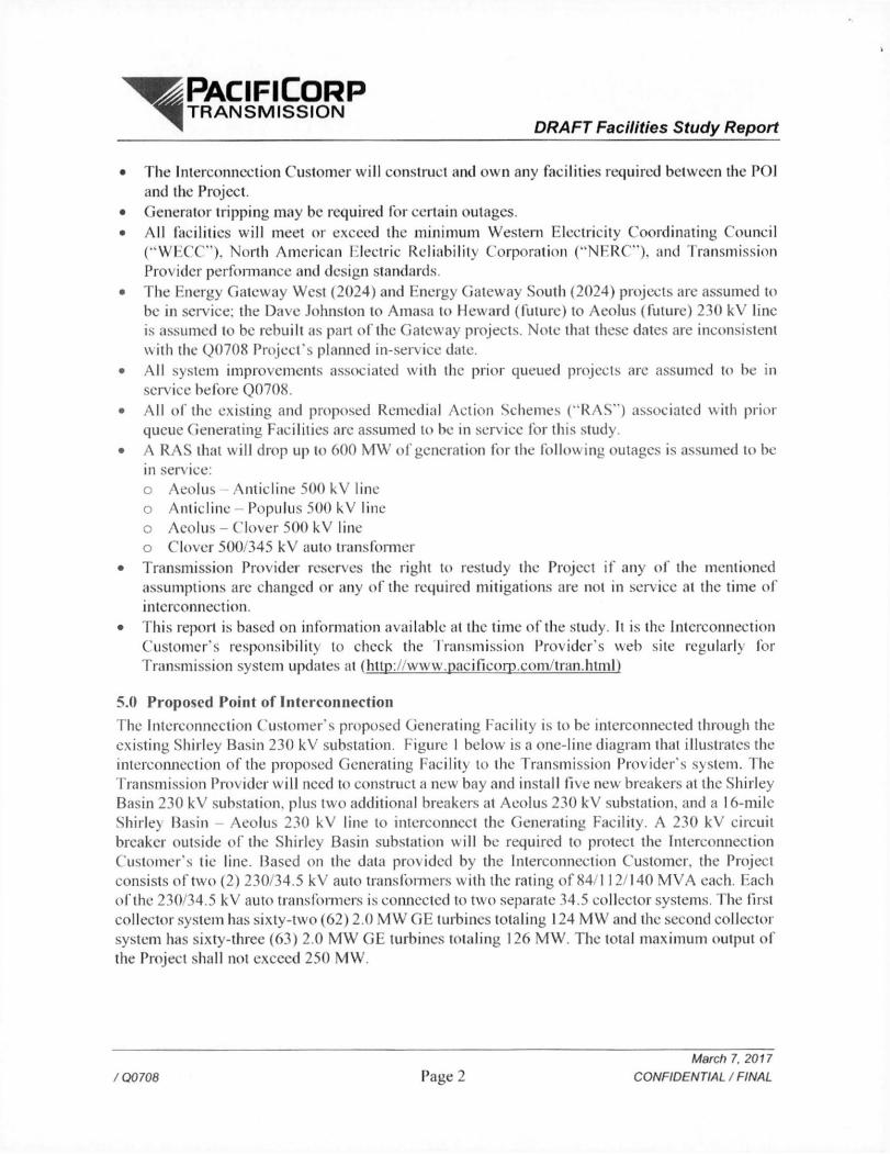
1.0 Description of the Project ("Interconnection Customer") proposed interconnecting 250 M W of new generation to PacifiCorp's ("Transmission Provider") Shirley Basin substation at 230 kV located in Carbon County. Wyoming. The project ("Project") wi l l consist o f 125 GE 2.0-116 turbines for a total output of 250 MW. The requested commercial operation date is July 1, 2018.
Interconnection Customer wi l l NOT operate this generator as a Qualified Facility as defined by the Public Utility Regulatory Policies Act o f 1978 (PURPA).
The Transmission Provider has assigned the Project "Q0708."
2.0 Study Scope and Objectives The objective of the Facilities Study is to:
• Complete a facilities analysis, which shall specify and estimate the cost o f equipment, engineering, procurement, and construction required to address issues as outlined in the system impact study, and
• Provide a scope of work and an estimated cost and schedule for completing the scope of work.
3.0 Type of Interconnection Service
The Interconnection Customer has selected Energy Resource (ER) Interconnection Service.
4.0 Study Assumptions • Al l active higher priority transmission service and/or generator interconnection requests wi l l
be considered in this study and are listed in Appendix 1. I f any of these requests are withdrawn, the Transmission Provider reserves the right to restudy this request, as the results and conclusions contained within this study could significantly change.
• For study purposes there are two separate queues: o Transmission Service Queue: To the extent practical, all network upgrades that are required
to accommodate active transmission service requests wil l be modeled in this study. o Generation Interconnection Queue: Interconnection facilities associated with higher queue
interconnection requests wil l be modeled in this study. • The Interconnection Customer's request for energy or network resource interconnection
service in and of itself does not convey transmission service. Only a Network Customer may make a request to designate a generating resource as a Network Resource. Because the queue of higher priority transmission service requests may be different when a Network Customer requests network resource designation for this Generating Facility, the available capacity or transmission modifications, i f any. necessary to provide network resource interconnection service may be significantly different. Therefore, the Interconnection Customer should regard the results of this study as informational rather than final.
• This study assumes the Project wil l be integrated into Transmission Provider's system at the agreed upon Point of Interconnection ("POI"). Shirley Basin 230 kV substation.
/Q0708 Page 1 March 7,2017
CONFIDENTIAL / FINAL
PACIFICORP T R A N S M I S S I O N
DRAFT Facilities Study Report
• The Interconnection Customer wil l construct and own any facilities required between the POI and the Project.
• Generator tripping may be required for certain outages. • Al l facilities wil l meet or exceed the minimum Western Electricity Coordinating Council
( " W E C C " ) , North American Electric Reliability Corporation ("NERC"). and Transmission Provider performance and design standards.
• The Energy Gateway West (2024) and Energy Gateway South (2024) projects are assumed to be in service; the Dave Johnston to Amasa to Heward (future) to Aeolus (future) 230 kV line is assumed to be rebuilt as pail of the Gateway projects. Note that these dates are inconsistent with the Q0708 Project's planned in-service date.
• A l l system improvements associated with the prior queued projects are assumed to be in service before Q0708.
• Al l of the existing and proposed Remedial Action Schemes ("RAS") associated with prior queue Generating Facilities are assumed to be in service for this study.
• A RAS that w ill drop up to 600 MW of generation for the follow ing outages is assumed to be in sen ice: o Aeolus Anticline 500 kV line o Anticline - Populus 500 kV line o Aeolus - Clover 500 kV line o Clover 500/345 kV auto transformer
• Transmission Provider reserves the right to restudy the Project i f any of the mentioned assumptions are changed or any of the required mitigations are not in service at the time of interconnection.
• This report is based on information available at the time of the study. It is the Interconnection Customer's responsibility to check the transmission Provider's web site regularly for Transmission system updates at (ht tn: / w w w. pac i f.corn .com. 1 ran .html)
5.0 Proposed Point of Interconnection The Interconnection Customer's proposed Generating Facility is to be interconnected through the existing Shirley Basin 230 kV substation. Figure 1 below is a one-line diagram that illustrates the interconnection of the proposed Generating Facility to the Transmission Prov ider's system. The Transmission Provider wi l l need to construct a new bay and install five new breakers at the Shirley Basin 230 kV substation, plus two additional breakers at Aeolus 230 kV substation, and a 16-mile Shirley Basin - Aeolus 230 kV line to interconnect the Generating Facility. A 230 kV circuit breaker outside o f the Shirley Basin substation will be required to protect the Interconnection Customer's tie line. Based on the data provided by the Interconnection Customer, the Project consists of two (2) 230/34.5 kV auto transformers with the rating of 84/112/140 M V A each. Each of the 230/34.5 kV auto transformers is connected to two separate 34.5 collector systems. The first collector system has sixty-two (62) 2.0 MW GE turbines totaling 124 MW and the second collector system has sixty-three (63) 2.0 M W GE turbines totaling 126 MW. The total maximum output of the Project shall not exceed 250 MW.
/Q0708 Page 2 March 7.2017
CONFIDENTIAL / FINAL

^ P A C I F I C O R P ^ • T R A N S M I S S I O N
DRAFT Facilities Study Report
prop <**o Howard
Change of Ownership _ 4 _ _ _
Point of
Interconnection
4 Miles
Substation
Shirley Basin
I To To Proposed Dunlap
PCI Sob (or IQC707
®— 1
230kV i 84/112/140MVA -<*LjLl
?30 34 5kV z=9% -<*nn
34 5kV
-<*rp 34 5kV
Q0708 Substation
84/112/140 MVA 230- 34 5kV
2 = 9%
& S (jl 1*1
Collector Circuits Collector Circuits
-16 Miles New
Facilities
Proposed Aeolus Substation
Figure I: System One Line Diagram
/ Q0708 Page 3 March 7.2017
CONFIDENTIAL / FINAL
PACIFICORP T R A N S M I S S I O N
DRAFT Facilities Study Report
6.0 Scope of Work
6.1 Generating Facility Modifications The following outlines the design, procurement, construction, installation, and ownership of equipment at the Interconnection C ustomer's Generating f acility.
6.1.1 Interconnection C ustomer to be Responsible For
• Obtain all necessary permits, lands, rights of way and easements required for the construction and continued maintenance of the facilities required for the Q0708 Project. All easements and permits shall be recorded in the name of the Transmission Provider and shall be on forms acceptable to the Transmission Provider. Al l casements and rights of way wi l l be obtained for durations acceptable to the Transmission Provider; this includes all permits casements for ingress and egress prior to the start of construction.
• Provide a separate fenced area along the perimeter of the Interconnection Customer's Generating Facility in which the Transmission Provider can install a control house for any protection and communication equipment. This area will share a fence and ground grid with the Generating Facility and have separate access. AC station service for the control house wil l be supplied by the Interconnection Customer.
• Provide a CDEGS grounding analysis. • Design and install conduits, per Transmission Provider's standards, to the demarcation
point. • The collector substation batteries wi l l be sized to cany the communication equipment
with DC to DC conveners • Demonstrate the reactive capability of the facility and the voltage control system prior
to Commercial Operation. o Operate in voltage control mode with the ability to deliver power output to the POI
w ithin the range of »/- 0.95 power factor. (Please sec Standard Large Generator Interconnection Agreement, article 9.6.1 and 9.6.2 in OATT.) Any additional reactive compensation must be designed such that the discrete switching of the reactive device, i f required, does not cause step voltage changes greater than i 3% at an) load serving bus on the Transmission Provider's system.
o As required by NERC standard VAR-001 -1 a. the Transmission Provider wil l provide a voltage schedule for the POI. Generating Facilities should be operated so as to maintain the voltage at the POI. or other designated point as deemed appropriate by Transmission Provider, between 1.00 per unit to 1.04 per unit. The Transmission Provider may also specify a voltage and/or reactive power bandwidth as needed to coordinate with upstream voltage control dev ices such as on-load tap changers. At the Transmission Prov ider's discretion, these values might be adjusted depending on operating conditions.
o At low output levels, the Project needs to ensure that it maintains the power factor within ± 0.95 at the POI and minimizes the reactive power How towards the transmission system to prevent high voltages.
o Generating Facilities capable of operating with a voltage droop are required to do so. Voltage droop control enables proportionate reactive power sharing among
/Q0708 age 4 March 7,2017
CONFIDENTIAL / FINAL
^ ^ P A C I F I C O R P ^ • T R A N S M I S S I O N
DRAFT Facilities Study Report
Generating Facilities. Studies wi l l be required to coordinate voltage droop settings i f there are other facilities in the area. It wi l l be the Interconnection Customer's responsibility to ensure that a voltage coordination study is performed, in coordination with Transmission Provider, and implemented with appropriate coordination settings prior to unit testing,
o For areas with multiple Generating Facilities, additional studies may be required to determine whether critical interactions, including but not limited to control systems, exist. These studies, to be coordinated with Transmission Provider, wil l be the responsibility of the Interconnection Customer. I f the need for a master controller is identified, the cost and all related installation requirements wil l be the responsibility of the Interconnection Customer. While study costs of subsequent interconnection projects nearby wi l l be the responsibility of the new project, participation by the Q708 Project may be required post Commercial Operation to ensure Bulk Electric System reliability is maintained.
• Phasor Measurement Units (PMUs) wi l l be required. • Provide a standard model from the WECC Approved Dynamic Model Library prior to
interconnection. The list o f approved generator models is continually updated and is available on the http://www.WECC.biz website.
• A l l generators must meet the Federal Energy Regulatory Commission ("FERC") and WECC low voltage ride-through requirements as specified in the interconnection agreement.
• Please note that prior to back feed, Interconnection Customer must arrange distribution voltage retail meter service for electricity consumed by the Project and arrange back up station service for power that wil l be drawn from the transmission line when the Project is not generating. Interconnection Customer must call the PCCC Solution Center 1-800-640-2212 to arrange this service. Approval for back feed is contingent upon obtaining station service.
• The Interconnection Costumer wi l l provide the following data points from the Q0708 collector substation: o Analogs:
• Transformer # 1 real power • Transformer # 1 reactive power
Real power flow through 34.5 kV line feeder breaker T l -1 • Reactive power flow through 34.5 kV line feeder breaker T l - 1 • Real power How through 34.5 kV line feeder breaker T I -2 • Reactive power flow through 34.5 kV line feeder breaker T l -2 • Real power How through 34.5 kV line feeder breaker T l -3 • Reactive power flow through 34.5 kV line feeder breaker T l -3 • Real power How through 34.5 kV line feeder breaker T l -4 • Reactive power How through 34.5 kV line feeder breaker IT-4 • Real power How through 34.5 kV line feeder breaker T l -5 • Reactive power flow through 34.5 kV line feeder breaker T l -5 • Transformer # 2 real power • T ransformer if 2 reactive power
/ Q0708 Page 5 March 7.2017
CONFIDENTIAL / FINAL

^ I I P A C I F I C O R P ^ • T R A N S M I S S I O N
DRAFT Facilities Study Report
• Real power How through 34.5 kV line feeder breaker T2-1 • Reactive power How through 34.5 kV line feeder breaker T2-1 • Real power flow through 34.5 kV line feeder breaker T2-2 • Reactive power How through 34.5 kV line feeder breaker T2-2
Real power flow through 34.5 kV line feeder breaker T2-3 • Reactive power How through 34.5 kV line feeder breaker T2-3
Real power flow through 34.5 kV line feeder breaker T2-4 • Reactive power flow through 34.5 kV line feeder breaker T2-4 • Real power How through 34.5 kV line feeder breaker T2-5
Reactive power flow through 34.5 kV line feeder breaker T2-5 • A phase 230 kV transmission voltage • B phase 230 kV transmission voltage • C phase 230 kV transmission voltage • Av erage W ind speed • Average Plant Atmospheric Pressure (Bar) • Average Plant Temperature (Celsius)
o Status • 230 kV breaker T l • 34.5 kV collector circuit breaker T l -1 • 34.5 kV collector circuit breaker IT -2 • 34.5 kV collector circuit breaker T l -3 • 34.5 kV collector circuit breaker T l - 4 • 34.5 kV collector circuit breaker T l -5 • 230 kV breaker T2 • 34.5 k V collector circuit breaker T2-1 • 34.5 kV collector circuit breaker T2-2 • 34.5 kV collector circuit breaker T2-3 • 34.5 kV collector circuit breaker T2-4 • 34.5 kV collector circuit breaker T2-5
6.1.2 Transmission Provider to be Responsible For
• Design, procure and install a small control building at a location provided and prepared by the Interconnection Customer inside the Generating Facility fence line.
• The list of major equipment identified for this portion of the Project is as follows: o (1) small control building with AC and DC panels and temperature controlled
(1)125VDC, 1 OOAh battery bank o (1)130VDC, 12A battery charger o ( D G E D 2 0 R T U o ( I ) 24*' open frame rack (DNP 3.0 protocol with hard wired connections) o (1) router (to interface with meters and substation equipment)
• Revenue metering is required for each of the two Interconnection Customer power transformers and wi l l be located on the high side of each of the step-up transformers.
/Q0708 Page 6 March 7,2017
CONFIDENTIAL / FINAL
^ ^ P A C I F I C O R P ^ • T R A N S M I S S I O N
DRAFT Facilities Study Report
The primary metering transformers shall be combination C T / V T extended range high accuracy metering with ratios to be determined during the design phase o f the Project.
• The Transmission Provider wi l l design and procure the collector revenue metering panels. The panels shall be located inside the collector control house. The collector substation metering panel shall include two revenue quality meters, test switches, and all SCADA metering data terminated at a metering interposition block. o An Ethernet is required for retail sales and generation accounting via the MV-90
translation system.
6.2 Tie Line Requirements
The following outlines the design, procurement, construction, installation, and ownership of equipment associated with the radial line connecting the Interconnection Customer's Generating Facility to the Transmission Provider's POI substation.
6.2.1 Interconnection Customer to be Responsible For
• Obtain all necessary permits, lands, rights o f way and easements required for the construction and continued maintenance of the facilities required for the Q0708 Project.
• Design and install approximately four miles of 230 kV transmission line between the Q0708 Generating Facility and the Shirley Basin substation. The Transmission Provider requires that the bus is built to the Transmission Provider's 230 kV standard.
• Design and install lA" OPGW and attachment hardware per the Transmission Provider's standards with nodes and channel banks at both ends. The OPGW cable w ill be coiled on the above structure such that there is enough cable and conductor to reach the POI substation tower with normal sags. Also, provide all hardware for stringing of the last span of conductor and OPGW into the POI sub tower.
• This fiber is to be installed by the Interconnection Customer and upon acceptance wi l l be owned and maintained by Transmission Provider. Channels wi l l be crossed at Shirley Basin substation to the back bone communication system.
• Design and construct a single 23()kV circuit breaker, and associated equipment tic line substation adjacent to Shirley Basin substation with a common fence between the two facilities.
• The ground mats between the Shirley Basin and the tic line substation wil l be tied together; therefore, the Interconnection Customer must match the standards o f the Shirley Basin substation.
• Conduit wi l l be required to be installed between the two yards. The Interconnection Customer wil l provide their conduit drawings and install the necessary conduit to demarcation point at the Point of Interconnection. The Transmission Provider wi l l install the connecting conduit in the Shirley Basin substation.
• Design (per the Transmission Provider's standards) and install a dead-end structure with sulficicnt bus to allow for proper attachment to two 230 kV disconnect switches inside the Transmission Provider's substation. The line side sw itch wi l l be the change of ownership location.
/Q0708 Page 7 March 7.2017
CONFIDENTIAL / FINAL

DRAFT Facilities Study Report
• Provide the output from two sets of current transformers to be fed into the bus differential relays with a maximum current transformer ratio matching the maximum CT ratio of the breakers at Shirley Basin substation. The detection and clearing o f faults on the tic line between the tie line and the collector substations wi l l be the responsibility of the Interconnection Customer. Facilities must be installed to detect and isolate the line i f it is faulted in five cycles or less.
6.2.2 Transmission Provider to be Responsible For • The Transmission Provider wil l review the Interconnection Customer's design of the
proposed new transmission line, OPGW and connection to the Shirley Basin substation structure for general conformance with Transmission Provider's construction standards.
• Prov ide a CDEGS grounding analysis of the Shirley Basin and Aeolus substations. • Provide the Transmission Provider's construction standards and review the
Interconnection Customer's design for the last bus support structure located outside the POI substation fence line to ensure compatibility with the termination switch.
• Connect the Interconnection Customer's last span of bus to the 230 kV disconnect switch at the Point of Change of Ownership location, including the OPGW cable. The Transmission Provider wil l maintain this last bus span at the Interconnection Customer's expense.
• This short span of bus wil l be protected with redundant bus differential relay systems. The bus differential relays wi l l be located in Shirley Basin substation. The Interconnection Customer wi l l need to provide the output from two sets of current transformers to be fed into the bus differential relays with a maximum current transformer ratio matching the maximum CT ratio of the breakers at Shirley Basin substation. I f a fault is detected, both the 230 kV breakers in Shirley Basin substation and the 230 kV breaker in the Interconnection Customer's tie line substation wi l l be tripped.
• A relay at Shirley Basin substation wi l l monitor the voltage magnitude and frequency. I f the magnitude or frequency of the voltage is outside of normal range of operation a signal wil l be sent over the communication system to the collector substation. At the collector substation this signal is to trip open all of the 34.5 kV feeder breakers to disconnect the wind turbine generators. By tripping the 34.5 kV breakers instead of the 230 kV breakers, the station service to the Generating Facility is maintained to facilitate the restoration of the generation. This relay w i l l also have phase and ground directional overcurrent elements set to operate for faults in the line between Shirley Basin substation and the Interconnection Customer's collector substation and serve as a backup to the main protection installed by the Interconnection Customer.
^ ^ P A C I F I C O R P ^ • T R A N S M I S S I O N
/Q0708 Page 8 March 7,2017
CONFIDENTIAL / FINAL
PACIFICORP ^ • T R A N S M I S S I O N
DRAFT Facilities Study Report
6.3 Point of Interconnection The following outlines the design, procurement, construction, installation, and ownership o f equipment at the POI.
6.3.1 Interconnection Customer to be Responsible For • Obtain all necessary pennits, rights of way and easements required for the
construction at Shirley Basin substation.
6.3.2 Transmission Provider to be Responsible For • Complete design and construction of one transformer bay at Shirley Basin to
terminate the tie line in. Panel space wil l be required in the 230 kV control house. The following equipment wi l l be installed: o ( 5 ) - 2 3 0 kV circuit breaker o ( 5 ) - 2 3 0 k V C C V T o (3) - 230 kV CCVT combination metering units o (7) 230 kV disconnect switch o (2) - 230 kV motor operated disconnect with ground switch
• The interchange metering shall be designed for the total net generation of the Project. The Transmission Provider shall specify and order all interconnection revenue metering, including the instrument transformers, metering panels, junction box and secondary metering wire. The primary metering transformers shall be combination CT /VT extended range for high accuracy metering with ratios to be determined during the design phase of the Project.
• The metering design package wi l l include two revenue quality meters, test switch, with DNP real-lime digital data terminated at a metering interposition block. One meter wi l l be designated as the primary SCADA meter and a second meter wi l l be designated as backup with metering DNP data delivered to the alternate control center. The metering data wil l include bidirectional KWH KVARH, revenue quantities including instantaneous PF, MW, MVAR, MVA, including per phase voltage and amps data.
• An Ethernet connection is required for retail sales and generation accounting via the MV-90 translation system.
• Listed below is the data that wil l be supplied by the Shirley Basin substation, o Analogs:
• Net Generation real power • Net Generator reactive power • Interchange energy register
• From Tie Substation Adjacent to Aeolus o Status:
• 230 kV breaker
/Q0708 Page 9 March 7, 2017
CONFIDENTIAL / FINAL
PACIFICORP T R A N S M I S S I O N
DRAFT Facilities Study Report
6.4 Other The following outlines the design, procurement, construction, installation, and ownership o f equipment past the POI.
6.4.1 Interconnection C ustomer to be Responsible For
• The Project is not within the Transmission Prov ider's sen ice territory. Prior to back feed the Interconnection Customer must arrange station serv ice with the electric service provider holding the certificated service territory rights for the area in which the load is physically located. This will require a request by the electric service provider (or its transmission prov ider) to the Transmission Provider to procure the necessary transmission service rights to deliver the expected amount of backfeed to the Project on a firm basis, it is recommended by the Transmission Provider that this process be started by the Interconnection Customer at least 12 months prior to the requested backfeed date o f the Project.
6.4.2 Transmission Provider to be Responsible For • Complete design and construction of one transformer bay at Aeolus substation. Panel
space will be required in the 230 kV control house. The following equipment wil l be installed: o (2) - 230 kV circuit breaker o (4) 230 kV disconnect switch o ( I ) - 230 kV motor operated disconnect with ground switch o ( 3 ) - 2 3 0 k V C C V T s
• Construct a new 16-mile Shirley Basin-Aeolus 230 kV line with 2-1272 ACSR parallel to the existing 230 kV line between Freezeout substation and Shirley Basin substation. The line is to be constructed o f 2-pole type wood tangent structures and 3-polc wood angle and dead-end structures. The first structure located just outside of the substation wi l l be an unguyed steel dead-end tower to reduce the congestion of guy wires of exiting lines coming into each of the substations. The conductor will be a double bundle of 1272 ACSR '"Bittern" for each of the three phases. Two shield wires wi l l be installed on the new transmission line, one being a 3/8" HHS steel cable and the other being an OPGW fiber optic cable. There is existing OPGW fiber on the 230 kV line between Freezeout substation and Shirley Basin substation. This fiber wi l l be cut into the Aeolus substation and the Q0707 interface substation as they are built. This design is currently matching the existing line design; however, any variation in the final design may result in increased costs. I f the Q0707 project does not proceed or i f this Project desires an in-service date prior to Q0707 the additional fiber w ill be assigned to this Project.
• The new 230 kV line between Shirley Basin and Aeolus substations wil l be protected with a line current differential relay system. Faults on the two 230 kV buses that arc created by the reconfiguration of the Shirley Basin substation bus from a ring bus to a breaker and a half bus arrangement w ill be detected with new bus differential relays.
/Q0708 Page 10 March 7,2017
CONFIDENTIAL / FINAL
^ P A C I F I C O R P ^ • T R A N S M I S S I O N
DRAFT Facilities Study Report
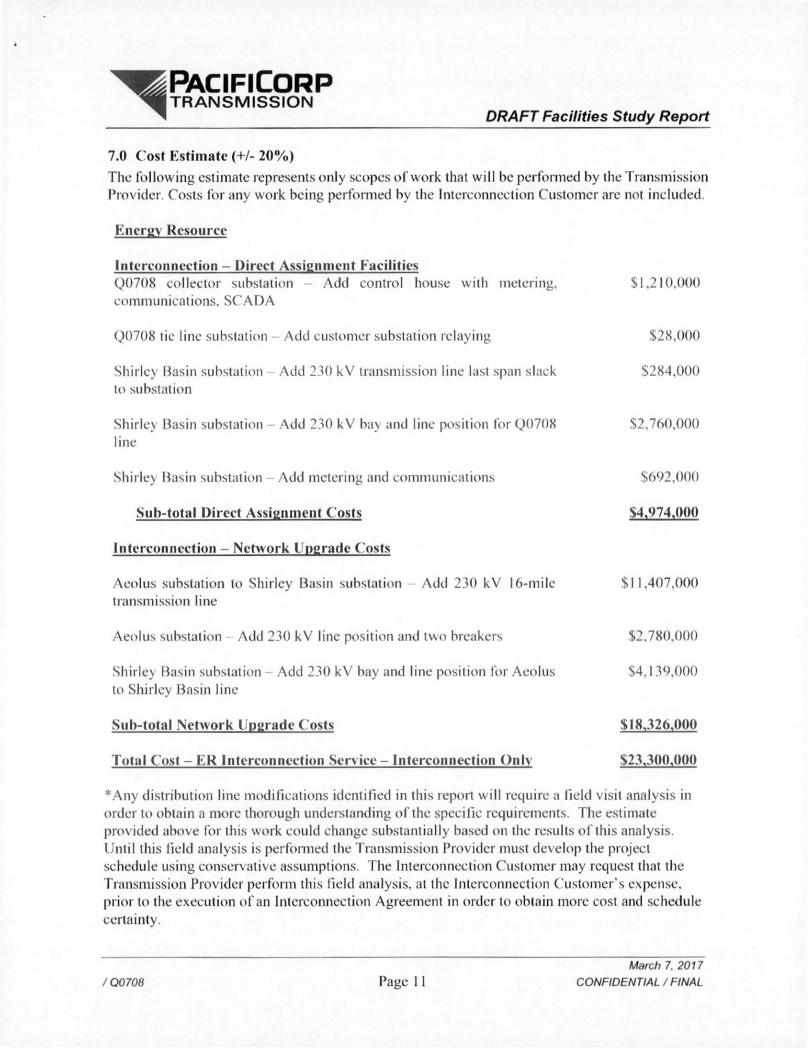
7.0 Cost Estimate (+/- 20%) The follow ing estimate represents only scopes of work that wil l be performed by the Transmission Provider. Costs for any work being performed by the Interconnection Customer are not included.
Energy, Resource
Interconnection - Direct Assignment Facilities Q0708 collector substation Add control house with metering. $1,210,000 communications, SCADA
Q0708 tic line substation - Add customer substation relaying $28,000
Shirley Basin substation Add 230 kV transmission line last span slack $284,000 to substation
Shirley Basin substation - Add 230 kV ba\ and line position for Q0708 $2,760,000 line
Shirle} Basin substation - Add metering and communications $692,000
Sub-total Direct Assignment Costs $4,974,000
Interconnection - Network Upgrade Costs
Aeolus substation to Shirley Basin substation Add 230 kV 16-mile $11,407,000 transmission line
Aeolus substation Add 230 kV line position and two breakers $2,780,000
Shirle) Basin substation - Add 230 kV bay and line position for Aeolus $4.139.000 to Shirley Basin line
Sub-total Network Upgrade Costs $18,326,000
Total Cost - E R Interconnection Service - Interconnection Only $23,300,000
*Any distribution line modifications identified in this report wil l require a field visit analysis in order to obtain a more thorough understanding of the specific requirements. The estimate prov ided above for this work could change substantially based on the results of this analysis. Until this field analysis is performed the Transmission Provider must develop the project schedule using conservative assumptions. The Interconnection Customer may request that the Transmission Provider perform this field analysis, at the Interconnection Customer's expense, prior to the execution of an Interconnection Agreement in order to obtain more cost and schedule certainty.
/ Q0708 Page 11 March 7.2017
CONFIDENTIAL / FINAL
PACIFICORP T R A N S M I S S I O N
DRAFT Facilities Study Report
Note: Costs for any excavation, duct installation and casements shall be borne by the Interconnection Customer and are not included in this estimate. This estimate is as accurate as possibly given the level of detailed study that has been completed to date and approximates the costs incurred by Transmission Provider to interconnect this Generator Facility to Transmission Provider's electrical distribution or transmission system. The Interconnection Customer wi l l be responsible for all actual costs, regardless of the estimated costs communicated to or approv ed by the Interconnection Customer.
/Q0708 Page 12 March 7,2017
CONFIDENTIAL / FINAL
^ P A C I F I C O R P ^ • T R A N S M I S S I O N
DRAFT Facilities Study Report
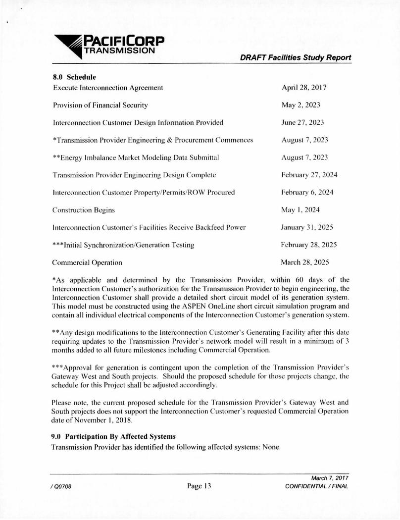
8.0 Schedule
Execute Interconnection Agreement
Provision of Financial Security
Interconnection Customer Design Information Provided
Transmission Provider Engineering & Procurement Commences
**Encrgy Imbalance Market Modeling Data Submittal
Transmission Provider Engineering Design Complete
Interconnection Customer Property/Permits/ROW Procured
Construction Begins
Interconnection Customer s Facilities Receive Backfeed Power
• • • In i t i a l Synchronization/Generation Testing
Commercial Operation
April 28. 2017
May 2, 2023
June 27, 2023
August 7, 2023
August 7. 2023
February 27, 2024
February 6, 2024
May 1. 2024
January 31. 2025
February 28, 2025
March 28. 2025
*As applicable and determined by the Transmission Provider, within 60 days o f the Interconnection Customer's authorization for the Transmission Provider to begin engineering, the Interconnection Customer shall provide a detailed short circuit model of its generation system. This model must be constructed using the ASPEN OneLine short circuit simulation program and contain all indiv idual electrical components of the Interconnection Customer's generation system.
**Any design modifications to the Interconnection Customer's Generating f acility after this date requiring updates to the Transmission Provider's network model wil l result in a minimum of 3 months added to all future milestones including Commercial Operation.
***Approval for generation is contingent upon the completion of the Transmission Provider's Gateway West and South projects. Should the proposed schedule for those projects change, the schedule for this Project shall be adjusted accordingly.
Please note, the current proposed schedule for the Transmission Provider's Gateway West and South projects does not support the Interconnection Customer's requested Commercial Operation date of November 1,2018.
9.0 Participation By Affected Systems Transmission Provider has identified the following affected systems: None.
/Q0708 Page 13 March 7,2017
CONFIDENTIAL / FINAL
PACIFICORP T R A N S M I S S I O N
DRAFT Facilities Study Report
10.0 Append ices-
Appendix I : Higher Priority Requests
Appendix 2: Property Requirements
/Q0708 Page 14 March 7,2017
CONFIDENTIAL / FINAL
^ ^ P A C I F l C O R P ^ • T R A N S M I S S I O N
DRAFT Facilities Study Report
10.1 Appendix I: Higher Priority Request A l l active higher priority transmission service and/or generator interconnection requests wi l l be considered in this study and arc identified below. I f any of these requests are withdrawn, the Transmission Provider reserves the right to restudy this request, as the results and conclusions contained within this study could significantly change.
Transmission/Generation Interconnection Queue Requests considered:
Q0199 (200 MW) Q0200(100MW) Q020I (100MW) Q0290 (252 MW) Q0306/335 (80 M W ) Q0375 (230 M W ) Q0409 (320 MW) Q0542 (240 MW) Q0706(250 M W ) Q0707 (250 MW)
/ Q0708 Page 15 March 7.2017
CONFIDENTIAL / FINAL
^^PACIF lCORP ^ • T R A N S M I S S I O N
DRAFT Facilities Study Report
10.2 Appendix 2: Property' Requirements
Property Requirements for Point of Interconnection Substation
Requirements for rights of way easements Rights o f way easements wi l l be acquired by the Interconnection Customer in the Transmission Provider's name for the construction, reconstruction, operation, maintenance, repair, replacement and removal of Transmission Provider's Interconnection Facilities that wi l l be owned and operated by Transmission Provider. Interconnection Customer wi l l acquire all ncccssaiy permits for the Project and wil l obtain rights of way easements for the Project on Transmission Provider's easement form.
Real Property Requirements for Point of Interconnection Substation Real property for a POI substation wi l l be acquired by an Interconnection Customer to accommodate the Interconnection Customer's project. The real property must be acceptable to Transmission Provider. Interconnection Customer wi l l acquire fee ownership for interconnection substation unless Transmission Provider determines that other than fee ownership is acceptable; however, the form and instrument of such rights wil l be at Transmission Provider's sole discretion. Any land rights that Interconnection Customer is planning to retain as part of a fee property conveyance wil l be identified in advance to Transmission Provider and are subject to the Transmission Prov ider's approval.
The Interconnection Customer must obtain all pennits required by all relevant jurisdictions for the planned use including but not limited to conditional use permits, Certificates o f Public Convenience and Necessity, California Environmental Quality Act, as well as all construction permits for the Project.
Interconnection Customer wil l not be reimbursed through network upgrades for more than the market value of the property.
As a minimum, real property must be environmentally, physically, and operationally acceptable to Transmission Provider. The real property shall be a permitted or permittable use in all zoning districts. The Interconnection Customer shall provide Transmission Provider with a title report and shall transfer property without any material defects of title or other encumbrances that are not acceptable to Transmission Provider. Property lines shall be surveyed and show all encumbrances, encroachments, and roads.
Examples o f potentially unacceptable environmental, physical, or operational conditions could include but are not limited to:
I . Environmental: known contamination o f site; evidence o f env ironmental contamination by any dangerous, hazardous or toxic materials as defined by any governmental agency; violation of building, health, safety, environmental, fire, land use, zoning or other such regulation; violation o f ordinances or statutes of any governmental entities having jurisdiction over the property; underground or above ground storage tanks in area; known remediation sites on property; ongoing
/Q0708 Page 16 March 7,2017
CONFIDENTIAL / FINAL
PACIFICORP T R A N S M I S S I O N
DRAFT Facilities Study Report
mitigation activities or monitoring activities; asbestos; lead-based paint, etc. A phase I environmental study is required for land being acquired in fee by the Transmission Provider unless waived by Transmission Provider.
2. Physical: inadequate site drainage; proximity to Hood zone; erosion issues; wetland overlays; threatened and endangered species; archeological or culturally sensitive areas: inadequate sub-surface elements, etc. Transmission Provider may require Interconnection Customer to procure various studies and surveys as determined necessary by Transmission Provider.
Operational: inadequate access for Transmission Provider's equipment and vehicles; existing structures on land that require removal prior to building of substation; ongoing maintenance for landscaping or extensive landscape requirements; ongoing homeowner's or other requirements or restrictions (e.g.. Covenants, Codes and Restrictions, deed restrictions, etc.) on property which are not acceptable to the Transmission Provider.
/Q0708 Page 17 March 7.2017
CONFIDENTIAL / FINAL