Embed Size (px)
Citation preview
The enclosed report contains the data and analysis summary for the SoniCalipershaft caliper, performed at Tower (Test Shaft), San Francisco, CA on Thursday,October 15, 2015 by MC. The shaft was calipered from a reference depth of 30.0feet to a depth of 210.0 feet. The shaft excavation was supported by a temporary,100.00 feet deep, 74.00 inches I.D., 1.00 inches thick steel casing. The thicknessof the casing itself, if temporary, was added to the total volume calculation.
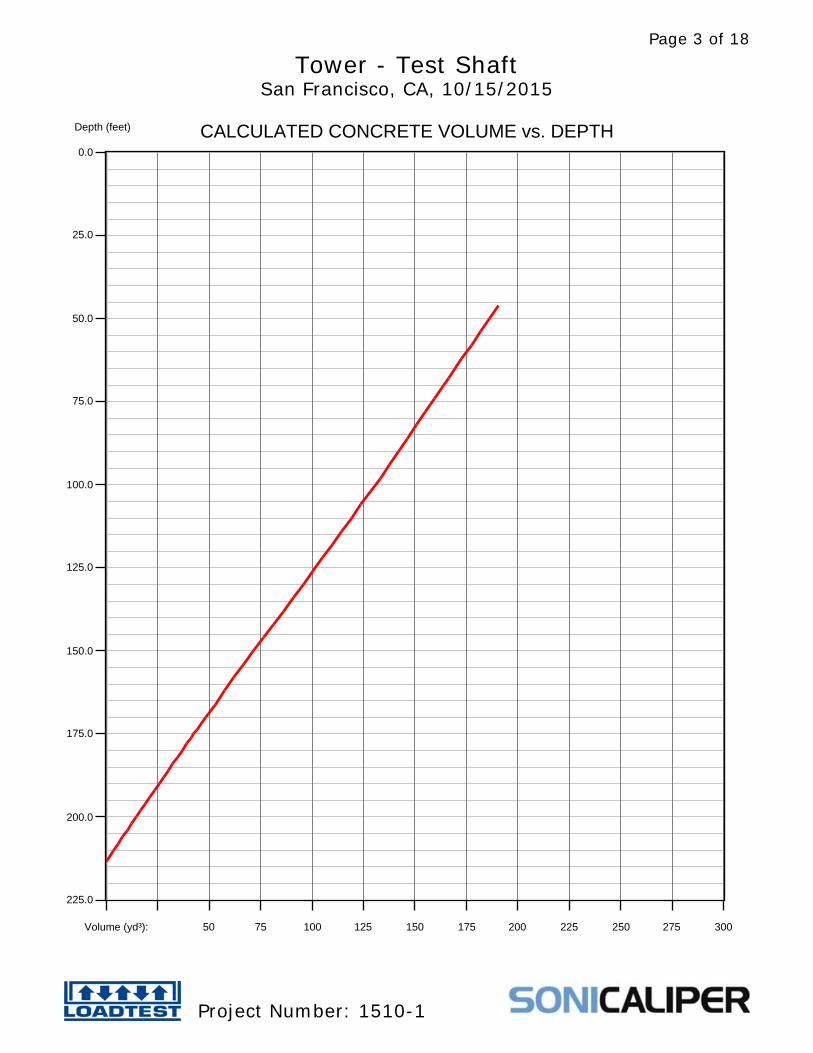
The minimum concrete volume is calculated to be 190.5 yd³, based on the area ofthe calipered cross-sections and a Top of Concrete depth of 46.0 feet. (Note thatthis includes theoretical volume based on a nominal shaft cross-sectional areabetween depths of 210.0 feet and 213.3 feet, which was not calipered.)
Tower - Test ShaftSan Francisco, CA, 10/15/2015
Project Number: 1510-1
Page 1 of 18

Depth (feet)
0.0
25.0
50.0
75.0
100.0
125.0
150.0
175.0
200.0
225.0
VERTICAL PROFILE
Radius (inches): -50.00 -40.00 -30.00-20.00 -10.00 0.00 10.00 20.00 30.00 40.00 50.00
Section alignment 64.0º
Tower - Test ShaftSan Francisco, CA, 10/15/2015
Project Number: 1510-1
Page 2 of 18
Depth (feet)
0.0
25.0
50.0
75.0
100.0
125.0
150.0
175.0
200.0
225.0
CALCULATED CONCRETE VOLUME vs. DEPTH
Volume (yd³): 50 75 100 125 150 175 200 225 250 275 300
Tower - Test ShaftSan Francisco, CA, 10/15/2015
Project Number: 1510-1
Page 3 of 18
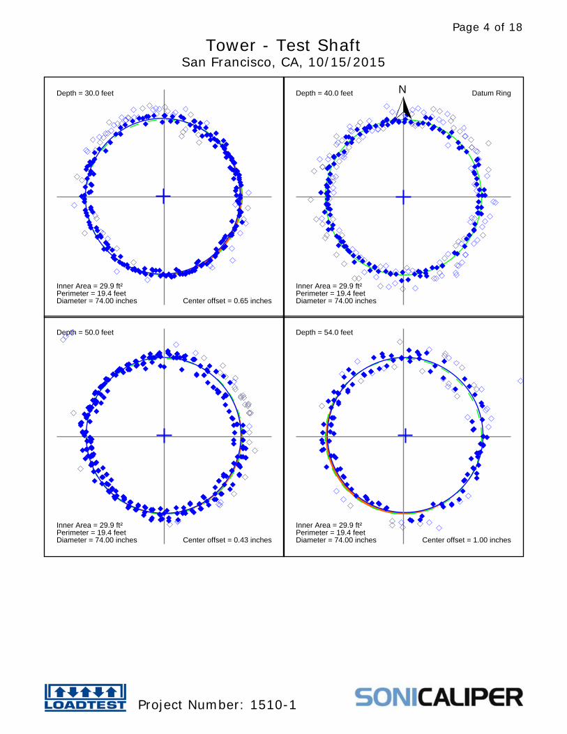
Depth = 30.0 feet
Inner Area = 29.9 ft²Perimeter = 19.4 feetDiameter = 74.00 inches Center offset = 0.65 inches
Depth = 40.0 feet
Inner Area = 29.9 ft²Perimeter = 19.4 feetDiameter = 74.00 inches
Datum RingN
Depth = 50.0 feet
Inner Area = 29.9 ft²Perimeter = 19.4 feetDiameter = 74.00 inches Center offset = 0.43 inches
Depth = 54.0 feet
Inner Area = 29.9 ft²Perimeter = 19.4 feetDiameter = 74.00 inches Center offset = 1.00 inches
Tower - Test ShaftSan Francisco, CA, 10/15/2015
Project Number: 1510-1
Page 4 of 18
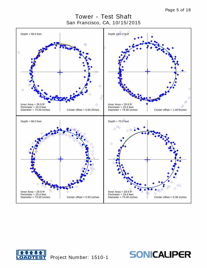
Depth = 58.0 feet
Inner Area = 29.9 ft²Perimeter = 19.4 feetDiameter = 74.00 inches Center offset = 0.65 inches
Depth = 62.0 feet
Inner Area = 29.9 ft²Perimeter = 19.4 feetDiameter = 74.00 inches Center offset = 1.00 inches
Depth = 68.0 feet
Inner Area = 29.9 ft²Perimeter = 19.4 feetDiameter = 74.00 inches Center offset = 0.93 inches
Depth = 70.0 feet
Inner Area = 29.9 ft²Perimeter = 19.4 feetDiameter = 74.00 inches Center offset = 0.36 inches
Tower - Test ShaftSan Francisco, CA, 10/15/2015
Project Number: 1510-1
Page 5 of 18
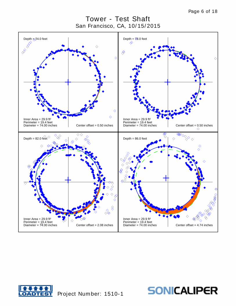
Depth = 74.0 feet
Inner Area = 29.9 ft²Perimeter = 19.4 feetDiameter = 74.00 inches Center offset = 0.50 inches
Depth = 78.0 feet
Inner Area = 29.9 ft²Perimeter = 19.4 feetDiameter = 74.00 inches Center offset = 0.50 inches
Depth = 82.0 feet
Inner Area = 29.9 ft²Perimeter = 19.4 feetDiameter = 74.00 inches Center offset = 2.08 inches
Depth = 86.0 feet
Inner Area = 29.9 ft²Perimeter = 19.4 feetDiameter = 74.00 inches Center offset = 4.74 inches
Tower - Test ShaftSan Francisco, CA, 10/15/2015
Project Number: 1510-1
Page 6 of 18
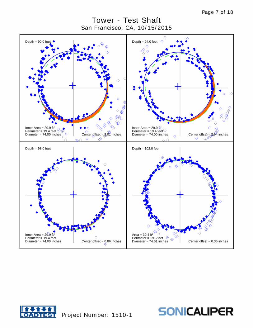
Depth = 90.0 feet
Inner Area = 29.9 ft²Perimeter = 19.4 feetDiameter = 74.00 inches Center offset = 3.01 inches
Depth = 94.0 feet
Inner Area = 29.9 ft²Perimeter = 19.4 feetDiameter = 74.00 inches Center offset = 2.94 inches
Depth = 98.0 feet
Inner Area = 29.9 ft²Perimeter = 19.4 feetDiameter = 74.00 inches Center offset = 0.86 inches
Depth = 102.0 feet
Area = 30.4 ft²Perimeter = 19.5 feetDiameter = 74.61 inches Center offset = 0.36 inches
Tower - Test ShaftSan Francisco, CA, 10/15/2015
Project Number: 1510-1
Page 7 of 18
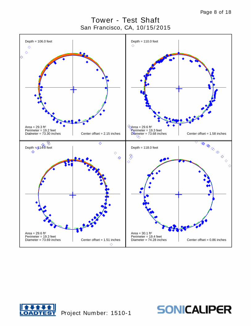
Depth = 106.0 feet
Area = 29.3 ft²Perimeter = 19.2 feetDiameter = 73.30 inches Center offset = 2.15 inches
Depth = 110.0 feet
Area = 29.6 ft²Perimeter = 19.3 feetDiameter = 73.68 inches Center offset = 1.58 inches
Depth = 114.0 feet
Area = 29.6 ft²Perimeter = 19.3 feetDiameter = 73.69 inches Center offset = 1.51 inches
Depth = 118.0 feet
Area = 30.1 ft²Perimeter = 19.4 feetDiameter = 74.28 inches Center offset = 0.86 inches
Tower - Test ShaftSan Francisco, CA, 10/15/2015
Project Number: 1510-1
Page 8 of 18
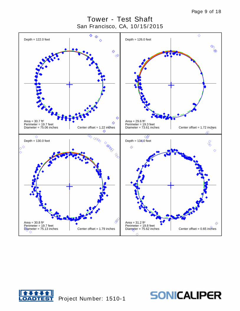
Depth = 122.0 feet
Area = 30.7 ft²Perimeter = 19.7 feetDiameter = 75.06 inches Center offset = 1.22 inches
Depth = 126.0 feet
Area = 29.6 ft²Perimeter = 19.3 feetDiameter = 73.61 inches Center offset = 1.72 inches
Depth = 130.0 feet
Area = 30.8 ft²Perimeter = 19.7 feetDiameter = 75.13 inches Center offset = 1.79 inches
Depth = 134.0 feet
Area = 31.2 ft²Perimeter = 19.8 feetDiameter = 75.62 inches Center offset = 0.65 inches
Tower - Test ShaftSan Francisco, CA, 10/15/2015
Project Number: 1510-1
Page 9 of 18
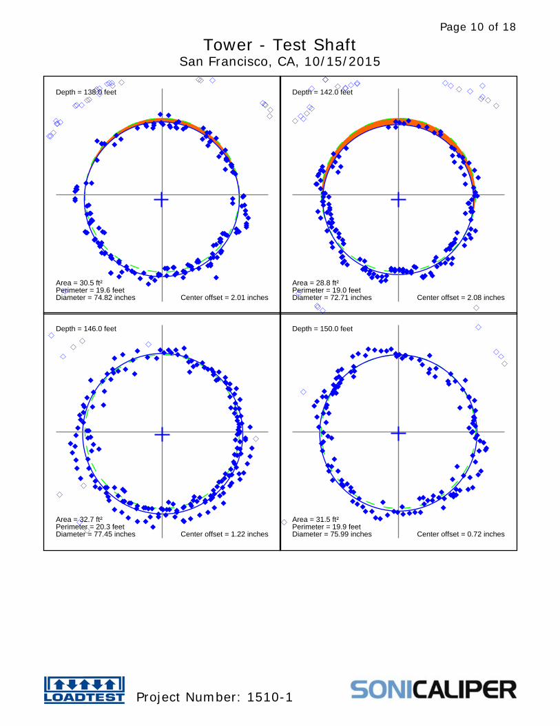
Depth = 138.0 feet
Area = 30.5 ft²Perimeter = 19.6 feetDiameter = 74.82 inches Center offset = 2.01 inches
Depth = 142.0 feet
Area = 28.8 ft²Perimeter = 19.0 feetDiameter = 72.71 inches Center offset = 2.08 inches
Depth = 146.0 feet
Area = 32.7 ft²Perimeter = 20.3 feetDiameter = 77.45 inches Center offset = 1.22 inches
Depth = 150.0 feet
Area = 31.5 ft²Perimeter = 19.9 feetDiameter = 75.99 inches Center offset = 0.72 inches
Tower - Test ShaftSan Francisco, CA, 10/15/2015
Project Number: 1510-1
Page 10 of 18
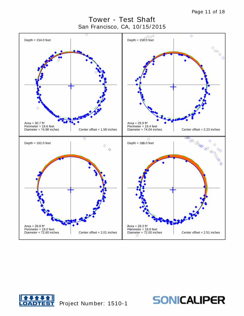
Depth = 154.0 feet
Area = 30.7 ft²Perimeter = 19.6 feetDiameter = 74.98 inches Center offset = 1.58 inches
Depth = 158.0 feet
Area = 29.9 ft²Perimeter = 19.4 feetDiameter = 74.04 inches Center offset = 2.23 inches
Depth = 162.0 feet
Area = 28.8 ft²Perimeter = 19.0 feetDiameter = 72.60 inches Center offset = 2.01 inches
Depth = 166.0 feet
Area = 28.3 ft²Perimeter = 18.8 feetDiameter = 72.00 inches Center offset = 2.51 inches
Tower - Test ShaftSan Francisco, CA, 10/15/2015
Project Number: 1510-1
Page 11 of 18
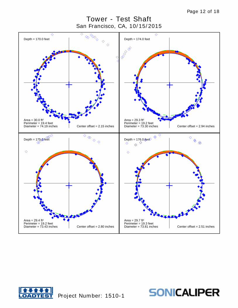
Depth = 170.0 feet
Area = 30.0 ft²Perimeter = 19.4 feetDiameter = 74.19 inches Center offset = 2.15 inches
Depth = 174.0 feet
Area = 29.3 ft²Perimeter = 19.2 feetDiameter = 73.30 inches Center offset = 2.94 inches
Depth = 175.0 feet
Area = 29.4 ft²Perimeter = 19.2 feetDiameter = 73.43 inches Center offset = 2.80 inches
Depth = 176.0 feet
Area = 29.7 ft²Perimeter = 19.3 feetDiameter = 73.81 inches Center offset = 2.51 inches
Tower - Test ShaftSan Francisco, CA, 10/15/2015
Project Number: 1510-1
Page 12 of 18

Depth = 178.0 feet
Area = 28.8 ft²Perimeter = 19.0 feetDiameter = 72.62 inches Center offset = 2.87 inches
Depth = 180.0 feet
Area = 29.0 ft²Perimeter = 19.1 feetDiameter = 72.86 inches Center offset = 3.59 inches
Depth = 182.0 feet
Area = 28.8 ft²Perimeter = 19.0 feetDiameter = 72.65 inches Center offset = 3.09 inches
Depth = 184.0 feet
Area = 28.3 ft²Perimeter = 18.8 feetDiameter = 72.00 inches Center offset = 2.87 inches
Tower - Test ShaftSan Francisco, CA, 10/15/2015
Project Number: 1510-1
Page 13 of 18
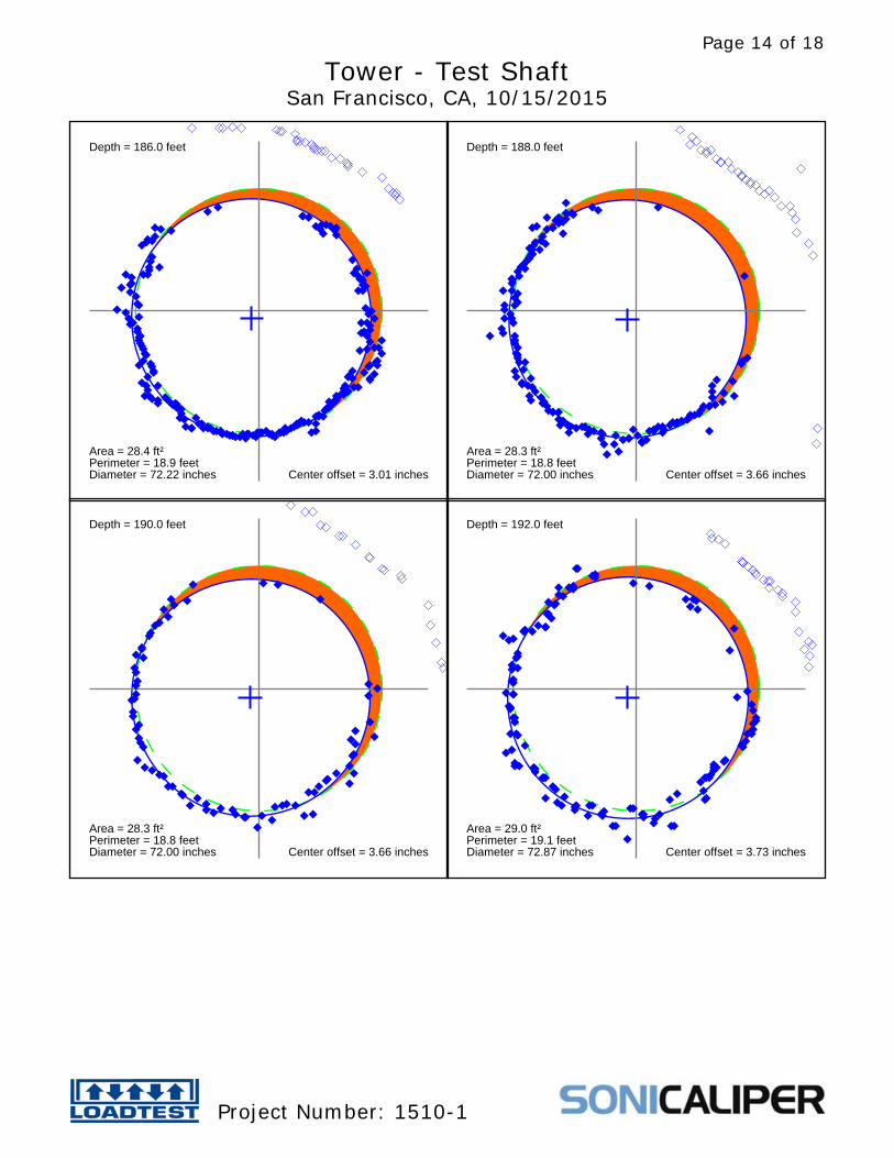
Depth = 186.0 feet
Area = 28.4 ft²Perimeter = 18.9 feetDiameter = 72.22 inches Center offset = 3.01 inches
Depth = 188.0 feet
Area = 28.3 ft²Perimeter = 18.8 feetDiameter = 72.00 inches Center offset = 3.66 inches
Depth = 190.0 feet
Area = 28.3 ft²Perimeter = 18.8 feetDiameter = 72.00 inches Center offset = 3.66 inches
Depth = 192.0 feet
Area = 29.0 ft²Perimeter = 19.1 feetDiameter = 72.87 inches Center offset = 3.73 inches
Tower - Test ShaftSan Francisco, CA, 10/15/2015
Project Number: 1510-1
Page 14 of 18

Depth = 194.0 feet
Area = 28.3 ft²Perimeter = 18.8 feetDiameter = 72.00 inches Center offset = 3.80 inches
Depth = 196.0 feet
Area = 28.3 ft²Perimeter = 18.8 feetDiameter = 72.00 inches Center offset = 4.02 inches
Depth = 198.0 feet
Area = 28.6 ft²Perimeter = 18.9 feetDiameter = 72.37 inches Center offset = 3.66 inches
Depth = 200.0 feet
Area = 28.3 ft²Perimeter = 18.8 feetDiameter = 72.00 inches Center offset = 4.38 inches
Tower - Test ShaftSan Francisco, CA, 10/15/2015
Project Number: 1510-1
Page 15 of 18
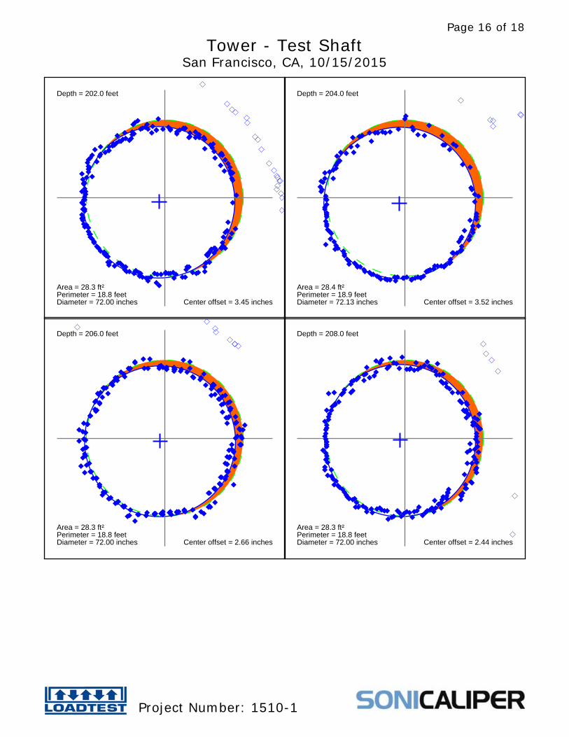
Depth = 202.0 feet
Area = 28.3 ft²Perimeter = 18.8 feetDiameter = 72.00 inches Center offset = 3.45 inches
Depth = 204.0 feet
Area = 28.4 ft²Perimeter = 18.9 feetDiameter = 72.13 inches Center offset = 3.52 inches
Depth = 206.0 feet
Area = 28.3 ft²Perimeter = 18.8 feetDiameter = 72.00 inches Center offset = 2.66 inches
Depth = 208.0 feet
Area = 28.3 ft²Perimeter = 18.8 feetDiameter = 72.00 inches Center offset = 2.44 inches
Tower - Test ShaftSan Francisco, CA, 10/15/2015
Project Number: 1510-1
Page 16 of 18

Depth = 210.0 feet
Area = 28.3 ft²Perimeter = 18.8 feetDiameter = 72.00 inches Center offset = 3.59 inches
Tower - Test ShaftSan Francisco, CA, 10/15/2015
Project Number: 1510-1
Page 17 of 18
DEEP FOUNDATION TESTING, EQUIPMENT & SERVICES SPECIALIZING IN OSTERBERG CELL (O-cell®) TECHNOLOGY
O-cell® and SoniCaliper® are registered trademarks.
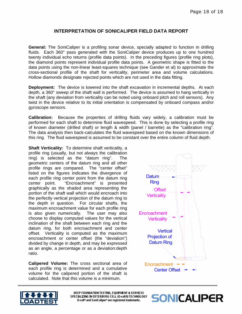
INTERPRETATION OF SONICALIPER FIELD DATA REPORT General: The SoniCaliper is a profiling sonar device, specially adapted to function in drilling fluids. Each 360° pass generated with the SoniCaliper device produces up to one hundred twenty individual echo returns (profile data points). In the preceding figures (profile ring plots), the diamond points represent individual profile data points. A geometric shape is fitted to the data points using the non-linear least-squares technique (see Gander et al) to approximate the cross-sectional profile of the shaft for verticality, perimeter area and volume calculations. Hollow diamonds designate rejected points which are not used in the data fitting. Deployment: The device is lowered into the shaft excavation in incremental depths. At each depth, a 360° sweep of the shaft wall is performed. The device is assumed to hang vertically in the shaft (any deviation from verticality can be noted using onboard pitch and roll sensors). Any twist in the device relative to its initial orientation is compensated by onboard compass and/or gyroscope sensors. Calibration: Because the properties of drilling fluids vary widely, a calibration must be performed for each shaft to determine fluid wavespeed. This is done by selecting a profile ring of known diameter (drilled shaft) or length & width (panel / barrette) as the “calibration ring”. The data analysis then back-calculates the fluid wavespeed based on the known dimensions of this ring. The fluid wavespeed is assumed to be constant over the entire column of fluid depth. Shaft Verticality: To determine shaft verticality, a profile ring (usually, but not always the calibration ring) is selected as the “datum ring”. The geometric centers of the datum ring and all other profile rings are compared. The “center offset” listed on the figures indicates the divergence of each profile ring center point from the datum ring center point. “Encroachment” is presented graphically as the shaded area representing the portion of the shaft wall which would encroach into the perfectly vertical projection of the datum ring to the depth in question. For circular shafts, the maximum encroachment value for each profile ring is also given numerically. The user may also choose to display computed values for the vertical inclination of the shaft between each ring and the datum ring, for both encroachment and center offset. Verticality is computed as the maximum encroachment or center offset (the “deviation”) divided by change in depth, and may be expressed as an angle, a percentage or as a deviation:depth ratio. Calipered Volume: The cross sectional area of each profile ring is determined and a cumulative volume for the calipered portion of the shaft is calculated. Note that this volume is a minimum.
VerticalProjection ofDatum Ring
OffsetVerticality
DatumRing
EncroachmentCenter Offset
EncroachmentVerticality
Page 18 of 18


![EccentriX™ - King Engine Bearings · The test rig uses an eccentric shaft located between two concentric shaft parts [4]. The test bearing, coupled with the eccentric shaft, is](https://img.pdfslide.net/doc/110x75/5f6f01203f6ec74f8174b83e/eccentrixa-king-engine-bearings-the-test-rig-uses-an-eccentric-shaft-located.jpg)