Embed Size (px)
Citation preview


Page 2 of 55
TRF No.: I0065__C TRF originator: BEAB
TEST REPORT EN 60065
Audio, video and similar apparatus Safety requirements
Report
Reference No. .................................... : 13003442 001
Tested by (+ signature) ...................... :(see cover page)
........................................................
Approved by (+ signature) ................. : (see cover page) ........................................................
Date of issue....................................... : (see cover page)
This report is based on a blank test report that was prepared by KEMA using information obtained from the TRF originator (see below).
Testing laboratory
Name .................................................. : TÜV Rheinland Product Safety GmbH
Address............................................... : Am Grauen Stein, D-51105 Köln
Testing location .................................. : (see cover page)
Address............................................... : (see cover page)
Client
Name .................................................. : (see cover page)
Address............................................... : (see cover page)
Test specification
Standard ............................................. : EN 60065:1998
Test procedure .................................. : CCA-scheme
Procedure deviation ........................... : CENELEC Common Modifications
Non-standard test method ................. : N.A.
Test Report Form/blank test report
Test Report Form No. ........................ : I0065__C/99-03
TRF originator..................................... : BEAB
Master TRF......................................... : reference No. 60065, dated 98-12
Copyright reserved to the bodies participating in the IECEE CB and/or the bodies participating in the CENELEC Certification Agreement (CCA).
Test item
Description.......................................... : LCD TV
Trademark .......................................... : 1) DMTECH, 2) INO Beyond Technology, 3) NEOVIA, 4) JNC, 5) SKY, 6) ROLSEN
Model and/or type reference.............. : 1) DML-4126W, DML-4126WL, DML-4126WD, DML-4126WDL DML-4126WX, DML-4126WXL, 2) FTV-26N4I, 3) NEO-26T, NEO-DVD26, NEO-DIVX26, 4) SST-26, SST-2600, 5) SLCD2603, 6) RL-26D20, RL-26D20D
Rating(s) ............................................. : AC 100-240 V, 50/60 Hz, 140 W

13003442 001 Page 3 of 55
TRF No.: I0065__C TRF originator: BEAB
Test case verdicts
Test case does not apply to the test object ..................: N(.A.)
Test item does meet the requirement...........................: P(ass)
Test item does not meet the requirement.....................: F(ail)
Testing
Date of receipt of test item ...........................................: 11.08.2004
Date(s) of performance of test ......................................: 11.08.2004 – 08.09.2004
General remarks:
“This report is not valid as a CB Test Report unless appended to a CB Test Certificate issued by a NCB, in accordance with IECEE 02”.
This test report shall not be reproduced except in full without the written approval of the testing laboratory.
The test results presented in this report relate only to the item tested.
“(see remark #)” refers to a remark appended to the report.
“(see appended table)” refers to a table appended to the report.
Throughout this report a point is used as the decimal separator.
Model descriptions and difference:
The product tested is a LCD TV, and has functions of TV and PC monitor with wireless headphone, CD player, DVD combo and/or Divx combo.
The basic model is DML-4126WXL.
Alternate models are identical to the basic model except for some functions. (see below.)
Trademark DMTECH INO Beyond Technology
NEOVIA JNC SKY ROLSEN
Normal DML-4126W
SST-26 RL-26D20
Normal + Wireless
DML-4126WL
NEO-26DT
DVD Combo DML-4126WD
SLCD2603 RL-26D20D
DVD Combo + Wireless
DML-4126WDL
FTV-26N4I NEO-DVD26
Divx Combo DML-4126WX
NEO-DIVX26
Divx Combo + Wireless
DML-4126WXL
SST-2600

13003442 001 Page 4 of 55
TRF No.: I0065__C TRF originator: BEAB
Manufacturer: (same as client)
Production Factorires: Factory 1: D.M. Technology Co., Ltd. Address: 36-1 Bangjiang Village East, Shilian Road, Shiji Town, Panyu Qu, Guangzhou City, Guangdong, P.R.China Factory 2: Viewtek Display Services. Address: Unit15 Tofts Farm Industrial Estast Hartlepool TS25 IQH, UK
Photo Documentation:
Photos (10 sheets)
13003442 001 Page 5 of 55
TRF No.: I0065__C TRF originator: BEAB
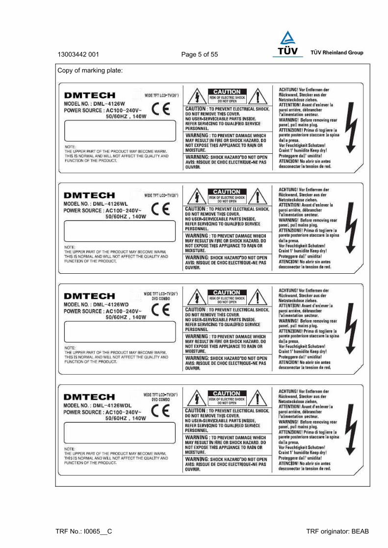
Copy of marking plate:

13003442 001 Page 6 of 55
TRF No.: I0065__C TRF originator: BEAB

13003442 001 Page 7 of 55
TRF No.: I0065__C TRF originator: BEAB
13003442 001 Page 8 of 55
TRF No.: I0065__C TRF originator: BEAB
13003442 001 Page 9 of 55
EN 60065
Clause Requirement − Test Result Verdict
TRF No.: I0065__C TRF originator: BEAB
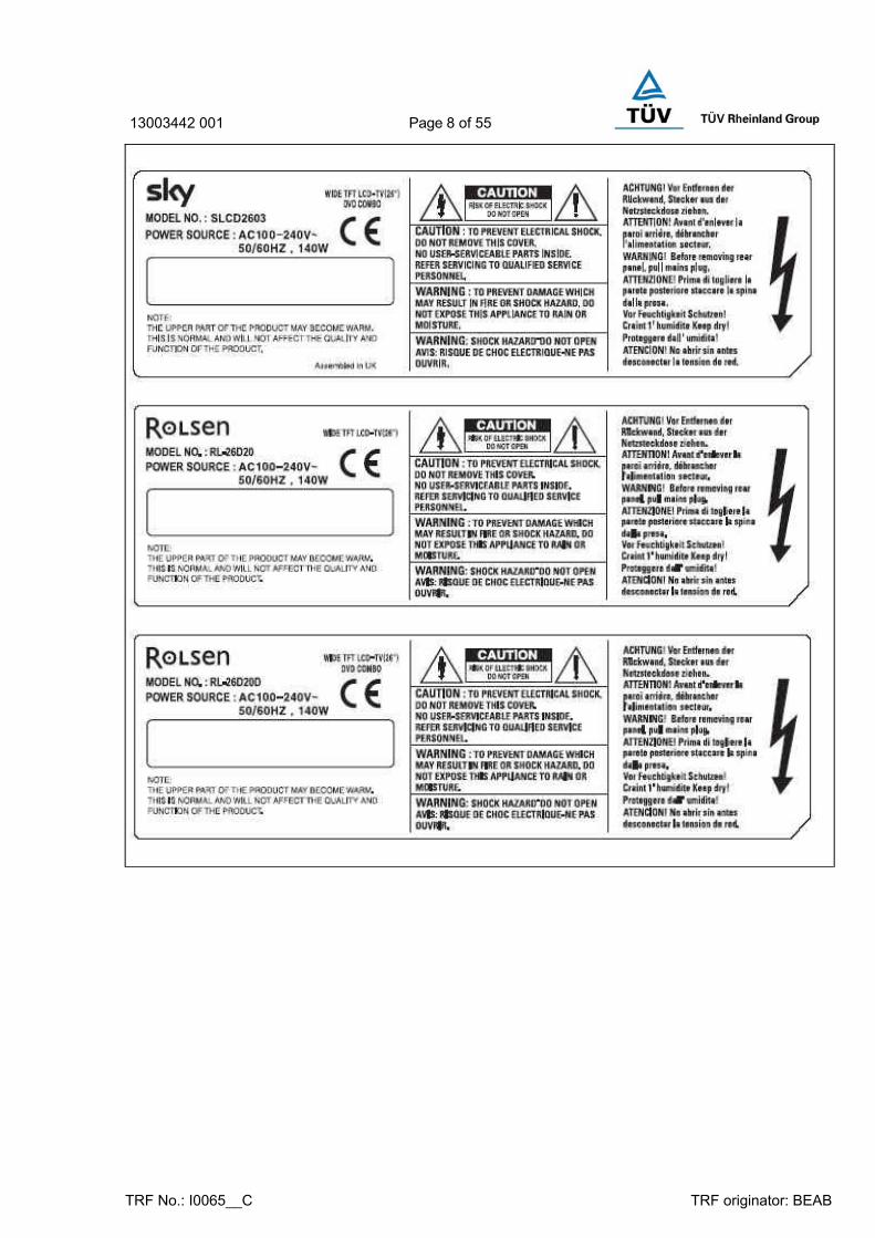
3 GENERAL REQUIREMENTS P
Safety class of the apparatus ................................. : Class I equipment P
4 GENERAL CONDITIONS OF TESTS P
4.1.4 Ventilation instructions require the use of the test box
No P
5 MARKING P
Comprehensible and easily discernible P
Permanent durability against water and petroleum spirit
P
5.1 Identification, maker, model .................................... : (see the copy of marking plate) P
Class II symbol N
Rated supply voltage and symbol .......................... : AC 100-240 V, 50/60 Hz P
Rated current or power consumption ..................... : 140 W P
5.2 Earth terminal Marked 60417-2-IEC-5019 P
Hazardous live terminals N
Supply output terminals (other than mains) N
5.3 Use of triangle with exclamation mark Marked in circuit diagram P
5.4 Instructions for use English P
5.4.1 Mains powered equipment not exposed to dripping or splashing
Described in the instruction manual
P
Hazardous live terminals, instructions for wiring No hazardous live terminal N
Instructions for replacing lithium battery Not used lithium battery N
Explanation of marking of the manually operated mechanical switch (MOMS)
“I” and “O” used P
5.4.2 Instructions for permanently connected equipment N
6 HAZARDOUS RADIATION P
6.1 Ionizing radiation ≤ 36 pA/kg (0.5 mR/h) LCD TV N
6.2 Laser radiation, emission limits to EN 60 825 ........ : The laser pickup is completely covered by plastic enclosure within the outer metal enclosure. (see appended table 14 and laser report)
P
Emission limits under fault conditions Class 1 Laser Product P

13003442 001 Page 10 of 55
EN 60065
Clause Requirement − Test Result Verdict
TRF No.: I0065__C TRF originator: BEAB
7 HEATING UNDER NORMAL OPERATING CONDITIONS P
7.1 Temperature rises not exceeding specified values, no operation of fuse links
(see appended table 7.1) P
7.1.1 Temperature rise of accessible parts (see appended table 7.1) P
7.1.2 Temperature rise of parts providing electrical insulation
(see appended table 7.1) P
7.1.3 Temperature rise of parts acting as a support or as a mechanical barrier
(see appended table 7.1) P
7.1.4 Temperature rise of windings (see appended table 7.1) P
7.1.5 Parts not subject to a limit under 7.1.1 to 7.1.4 (see appended table 7.1) P
7.2 Softening temperature of insulating material supporting parts conductively connected to the mains carrying a current > 0.2 A at least 150 °C
(see appended table 7.2) P
8 CONSTRUCTIONAL REQUIREMENTS WITH REGARD TO THE PROTECTION AGAINST ELECTRIC SHOCK
P
8.1 Conductive parts covered by lacquer, paper, untreated textile oxide films and beads etc. considered to be bare
Considered P
8.2 No shock hazard when changing voltage setting device, fuse-links or handling drawers etc.
No change of voltage setting or fuse by hand
N
8.3 Insulation of hazardous live parts not provided by hygroscopic material
No hygroscopic material N
8.4 No risk of electric shock following the removal of a cover which can be removed by hand
P
8.5 Class I equipment Earthing supplied by the approved inlet
P
Basic insulation between hazardous live parts and earthed accessible parts
Basic insulation supplied P
Capacitors bridging basic insulation complying with 14.2.1a
Certified Y1 capacitor used (see appended table 14)
P
Basic insulation bridged by components complying with 14.3.4.3
N
8.6 Class II equipment and Class II constructions within Class I equipment
P
Reinforced or double insulation between hazardous live parts and accessible parts
Satisfactory double or reinforced
P
Components bridging reinforced or double insulation complying with 14.1 a) or 14.3
Approved resister(R803) and transformer(T801) used (see appended table 14)
P

13003442 001 Page 11 of 55
EN 60065
Clause Requirement − Test Result Verdict
TRF No.: I0065__C TRF originator: BEAB
Basic and supplementary insulation each being bridged by a capacitor complying with 14.2.1 a)
N
Reinforced or double insulation being bridged with 2 capacitors in series complying with 14.2.1 a)
N
Reinforced or double insulation being bridged with a single capacitor complying with 14.2.1 b)
(see appended table 14) P
8.7 Basic insulation between parts at 35 V to 71 V (peak) a.c. or 60 V to 120 V d.c. and accessible parts
No accessible parts exceeding at 35 V to 71 V (peak) a.c. or 60 V to 120 V d.c.
P
Reinforced or double insulation between circuits operating at between 35 V and 71 V (peak) a.c. or between 60 V and 120 V d.c. and hazardous live parts at higher voltage
All secondary circuits are isolated with double or reinforced insulation.
P
Separation by Class II isolating transformer P
Separation by Class I transformer N
Separation by earthed conductive part P
8.8 Basic or supplementary insulation ≥ 0.4 mm (mm) : N
Reinforced insulation ≥ 0.4 mm (mm) .................... : Thickness of transformer bobbin: min. 0.7 mm
P
Thin sheet insulation In transformer between primary and secondary used
P
Basic or supplementary insulation, at least two layers, each meeting 10.3
N
Basic or supplementary insulation, three layers any two of which meet 10.3
N
Reinforced insulation, two layers each of which meet 10.3
N
Reinforced insulation, three layers any two which meet 10.3
2 layers of insulation tape P
8.9 Adequate insulation between internal hazardous live conductors and accessible parts
Approved wires used P
Adequate insulation between internal hazardous live parts and conductors connected to accessible parts
P
8.10 Double insulation between conductors connected to the mains and accessible parts
Class I equipment N
8.11 Detaching of wires Approved connector used P
No undue reduction of creepage or clearance distances if wires become detached
P

13003442 001 Page 12 of 55
EN 60065
Clause Requirement − Test Result Verdict
TRF No.: I0065__C TRF originator: BEAB
Vibration test carried out ......................................... : No risk of wire becoming detached
P
8.12 Adequate cross-sectional area of internal wiring to mains socket-outlets
No socket-outlets N
8.13 Adequate fastening of windows, lenses, lamp covers etc. (pull test 20 N for 10 s)
N
8.14 Adequate fastening of covers (pull test 50 N, for 10 s)
No terminal blocks N
8.15 No risk of damage to the insulation of internal wiring due to hot parts or sharp edges
2N, no touched hazards part P
8.16 Only special supply equipment can be used N
9 ELECTRIC SHOCK HAZARD UNDER NORMAL OPERATING CONDITIONS P
9.1.1 Touch current measured from terminal devices using the network in Annex D ................................. :
U1: max. 1.16 Vpeak U2: max. 0.304 Vpeak
P
Discharge not exceeding 45 uC CN3 1-2: 5.377 uC CN3 1-G: 0.767 uC CN3 2-G: 2.026 uC
P
Energy of discharge not exceeding 350 mJ N
Test with test finger and test probe Considered P
9.1.2 No hazardous live shafts of knobs, handlers or levers
N
9.1.3 Ventilation holes tested by means of 4 mm x 100 mm test pin
3.9 mm of inside metal 3.9 mm of external enclosure
N
9.1.4 Terminal devices tested with 1 mm x 20 mm test pin (10 N); test probe 16 of IEC 61 032
No terminals contacted hazardous live parts
P
Terminal devices tested with 1 mm x 100 mm straight wire (1N); test probe D of IEC 61 032
No terminals contacted hazardous live parts
P
9.1.5 Pre-set controls tested with 2 mm x 100 mm test pin (10 N); test probe C of IEC 61 032
No pre-set controls N
9.1.6 No shock hazard due to stored charge on withdrawal of the mains plug; voltage (V) after 2 s :
0 V after 0.02 sec P
If C is not greater than 0.1 µF no test needed N
9.1.7 Enclosure sufficiently resistant to external force P
Test probe 11 of IEC 61 032 for 10 s (50 N) No touched hazardous part P
Test hook of fig. 4 for 10 s (20 N) P
30 mm diameter test tool for 5 s (100 or 250 N) .... : 100N P
9.2 No hazard after removing a cover by hand N

13003442 001 Page 13 of 55
EN 60065
Clause Requirement − Test Result Verdict
TRF No.: I0065__C TRF originator: BEAB
10 INSULATION REQUIREMENTS P
10.1 Insulation resistance (MΩ) at least 2 MΩ min. after surge test for basic and 4 MΩ min. for reinforced insulation
(see appended table 10.3) P
10.2 Humidity treatment 48 h or 120 h 48hr, 30°C, 95% (See appended table 10.3)
P
10.3 Insulation resistance and dielectric strength (See appended table 10.3) P
11 FAULT CONDITIONS P
11.1 No shock hazard under fault conditions See clause 9.1.1. P
11.2 Heating under fault condition (see appended table 11.2) P
No hazard from softening solder P
11.2.1 Measurement of temperature rises (see appended table 11.2) P
11.2.2 Temperature rise of accessible parts (see appended table 11.2) P
11.2.3 Temperature rise of parts, other than windings, providing electrical insulation
(see appended table 11.2) P
Temperature rise of printed circuit boards (PCB) exceeding the limits of Table 2 by max. 100 K for max. 5 min
N
a) Temperature rise of printed circuit boards (PCB) to 20.3.1, exceeding the limits of Table 2 by not more than 100 K for an area not greater than 2 cm²
N
b) Temperature rise of printed circuit boards (PCB) to 20.3.1 up to 300 K for an area not greater than 2 cm² for a maximum of 5 min
N
Meets all the special conditions if conductors on printed circuit boards are interrupted
N
11.2.4 Temperature rise of parts acting as a support or mechanical barrier
N
11.2.5 Temperature rise of windings (see appended table 11.2) P
11.2.6 Temperature rise of other parts not subject to the limits of 11.2.1 to 11.2.5
(see appended table 11.2) P
12 MECHANICAL STRENGTH P
12.1.1 Bump test Weight: 18.0 kg, no damaged P
12.1.2 Vibration test N
12.1.3 Impact test No damage P

13003442 001 Page 14 of 55
EN 60065
Clause Requirement − Test Result Verdict
TRF No.: I0065__C TRF originator: BEAB
12.2 Fixing of knobs, push buttons, keys and levers 50 N P
12.3 Remote controls with hazardous live parts N
12.4 Drawers (pull test 50 N, 10 s) N
12.5 Antenna coaxial sockets providing isolation N
13 PARTS CONNECTED TO THE SUPPLY MAINS P
13.1.1 Clearances and creepage distances in accordance with 13.2 (fig. 9); minimum distance ....................... :
Basic insulation: > 3.0mm Reinforced insulation: > 6.0mm
P
Reduction applied if the 3 conditions are met ........ : N
Reduction applied for Grade 2 winding wire .......... : N
13.1.2 Use of cemented joints ........................................... : N
Tests to confirm cemented joints N
13.2 Clearances and creepage distances of parts of different polarity connected to the mains, as in fig. 9; minimum distance ......................................... :
Cl/Cr is minimum 3.0mm P
Clearances and creepage distances between conductors on printed circuit boards, one of which may be conductively connected to the mains, as in fig. 10
P
13.3 Enclosed, enveloped or hermitically sealed parts: clearances and creepage distances to Table 4
Approved opto-couplers (see appended table 14)
P
13.4 Parts filled with insulating compound, meeting the requirements of 8.8
N
13.5 Type B coated printed circuit boards complying with IEC 60 664-3 (basic insulation only)
N
14 COMPONENTS P
14.1 Resistors P
a) Resistors between hazardous live parts and accessible metal parts
N
b) Resistors, other than between hazardous live parts and accessible parts
P
b) Resistors separately approved .......................... : Approved resister (see appended table 14)
P
14.2 Capacitors and RC units P
Capacitors separately approved (see appended table 14) P

13003442 001 Page 15 of 55
EN 60065
Clause Requirement − Test Result Verdict
TRF No.: I0065__C TRF originator: BEAB
14.2.1 Y capacitors tested to IEC 384-14, 2nd edition ....... : (see appended table 14) P
14.2.2 X capacitors tested to IEC 384-14, 2nd edition ....... : (see appended table 14) P
14.2.3 Capacitors operating at mains frequency but not connected to the mains: tests for X2 ...................... :
N
14.2.5 Capacitors with volume exceeding 1750 mm³, where short-circuit current exceeds 0.2 A: compliance with IEC 60 384-1, 4.38 category B or better ....................................................................... :
(see appended table 14) P
Capacitors with volume exceeding 1750 mm³, mounted closer to a potential ignition source than Table 5 permits: compliance with IEC 60 384-1, 4.38 category B or better ........................................ :
(see appended table 14) P
Shielded by a barrier to FV 0 or metal ................... : N
14.3 Inductors and windings P
14.3.1 Transformers and inductors marked with manufacturer’s name and type ............................... :
(see appended table 14) P
Transformers and inductors separately approved . : N
14.3.3.2 Transformers meet the constructional requirements
P
14.3.4.1 Class II transformers have adequate separation between hazardous live parts and accessible parts (double or reinforced insulation)
Provided with reinforced or double insulation between primary and secondary
P
Coil formers and partition walls ≥ 0.4 mm Thickness of transformer bobbin: min. 0.7mm
P
14.3.4.2 Class I transformers, with basic insulation and protective screening only if all 7 conditions of 14.3.4.2 are met
N
14.3.4.3 Separating transformers with at least basic insulation
N
14.3.5.1 Class II transformers have adequate insulation between hazardous live parts and accessible parts (double or reinforced insulation)
Provided with reinforced or double insulation between primary and secondary
P
Coil formers and partition walls ≥ 0.4 mm Thickness of transformer bobbin: min. 0.7mm
P
14.3.5.2 Class I transformers have adequate insulation between hazardous live parts and accessible conductive parts or those conductive parts or protective screens connected to a protective earth terminal
N
Winding wires connected to protective earth have adequate current-carrying capacity
N

13003442 001 Page 16 of 55
EN 60065
Clause Requirement − Test Result Verdict
TRF No.: I0065__C TRF originator: BEAB
14.4 High voltage components N
High-voltage components and assemblies: U > 4 kV (peak) separately approved
No high-voltage components N
Component meets category FV 1 of IEC 60 707 N
14.4.1 High voltage transformers and multipliers tested as part of the submission
N
14.5 Protective devices P
Protective devices used within their ratings Fuse(F801), 250V, T5AL P
External clearance and creepage distances appropriate for the voltage across the device when opened
P
14.5.1.1 a) Thermal cut-outs separately approved No thermal cut-out N
b) Thermal cut-outs tested as part of the submission
N
14.5.1.2 a) Thermal links separately approved N
b) Thermal links tested as part of the submission N
14.5.1.3 Thermal devices resettable by soldering N
14.5.2.1 Fuse-links in the mains circuit according to IEC 60 127
(see appended table 14) P
14.5.2.2 Correct marking of fuse-links adjacent to holder ... : Fuse(F801), 250V, T5AL P
14.5.2.3 Not possible to connect fuses in parallel ................ : No connect fuses in parallel N
14.5.2.4 Not possible to touch hazardous live parts when replacing fuse-links without the use of a tool ......... :
Equipment was constructed that hazardous live parts do not become accessible from the outside of the apparatus
P
14.5.3 PTC-S thermistors comply with IEC 60 738 No PTC-S thermistors N
PTC-S devices (15 W) category FV 1 or better No PTC-S devices N
14.5.4 Circuit protectors have adequate breaking capacity and their position is correctly marked
N
14.6 Switches P
14.6.1 Permanently connected equipment provided with an all-pole mains switch unless 5.4.2 is met
No permanently connected apparatus
N
14.6.2 Manually operated mechanical switch (MOMS), required where power consumption > 15 W and/or peak voltage > 4 kV; MOMS required .................... :
Used MOMS P
Switch readily accessible and not in mains cord P
Exception for automatic switching Automatic switching P
Exception for continuous operation N

13003442 001 Page 17 of 55
EN 60065
Clause Requirement − Test Result Verdict
TRF No.: I0065__C TRF originator: BEAB
14.6.3 Manually operated mechanical switch (MOMS): switch indication On position clearly discernible
On position “I”: LED red light P
Indication by marking meets Cl. 5 Light and symbols P
Indication of the OFF position “I” / “O” symbols double pole switch
P
14.6.4 Manually operated mechanical switch (MOMS) fitted, is there a Stand-by mode ............................. :
Marked with symbol (IEC 417, No. 5009)
P
Stand-by mode clearly discernible ......................... : P
Exception for low Stand-by current < 0.7 mA (peak)
N
14.6.5 Components bridging contacts of mains switches comply with 14.1 a) or 14.2.2
N
14.6.6 Manually operated mechanical switches (MOMS) separately approved to IEC 61 058-1
Used MOMS N
Manually operated mechanical switch (MOMS) tested as part of the equipment complies with 14.6.7, 14.6.10 and 20.1.4 and meets 14.6.8 and/or 14.6.9 and Annex G (G1.1)
N
14.7 Safety interlocks N
Safety interlocks to 2.8 of IEC 60 950 N
14.8 Voltage setting devices N
Voltage setting device not likely to be changed accidentally
N
14.9 Motors N
14.9.1 Endurance test on motors N
Motor start test N
Dielectric strength test N
14.9.2 Not adversely affected by oil or grease etc. N
14.9.3 Protection against moving parts N
14.9.4 Motors with phase-shifting capacitors, three-phase motors and series motors meet Cl. B.8, B.9 and B.10 of IEC 60 950, Annex B
N
14.10 Batteries N
14.10.1 Batteries mounted with no risk of accumulation of flammable gases
N
14.10.2 No possibility of recharging non-rechargeable batteries
N
14.10.3 Recharging currents and times within manufacturers limits
N

13003442 001 Page 18 of 55
EN 60065
Clause Requirement − Test Result Verdict
TRF No.: I0065__C TRF originator: BEAB
Lithium batteries discharge and reverse currents within the manufacturers limits
N
14.11 Optocouplers P
Optocouplers comply with Cl. 8 (see appended table 14) P
Internal and external dimensions to 13.1.1 (see appended table 14) P
15 TERMINALS P
15.1.1 Mains plug, appliance inlet, interconnection couplers and mains socket-outlet meet the appropriate standard
(see appended table 14) P
15.1.2 Connectors for antenna, earth, audio, video or data: P
No risk of insertion in mains socket-outlets No main socket-outlets P
No risk of insertion into audio or video: outlets marked with the symbol of 5.2
P
15.1.3 Output terminals of AC adaptors or similar devices not compatible with household mains socket-outlets
N
15.2 Provision for protective earthing P
Accessible conductive parts of Class I equipment reliably connected to earth terminal, within equipment
Appliance inlet used P
Class I supply equipment with non-hazardous live output voltage: output circuit not connected to earth
N
Protective earth conductors correctly coloured Green/yellow wire used for protective earth conductors
P
Equipment with non-detachable mains cord provided with separate protective earth terminal near mains input
Detachable mains cord type N
Protective earth terminal resistant to corrosion P
Earth resistance (Ω) ≤ 0.1 Ω at 25 A ...................... : 0.034 Ω P
15.3 Terminals for external flexible cords and for permanent connection to the mains supply
N
15.3.1 Adequate terminals for connection of permanent wiring
Not be permanently connected apparatus
N
15.3.2 Reliable connection of non-detachable cords: N
Not soldered to conductors of a printed circuit board
N
adequate clearances and creepage distances N
13003442 001 Page 19 of 55
EN 60065
Clause Requirement − Test Result Verdict
TRF No.: I0065__C TRF originator: BEAB
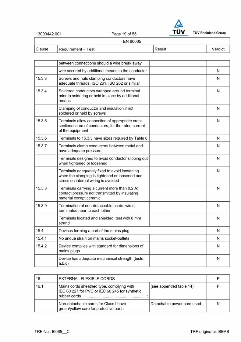
between connections should a wire break away
wire secured by additional means to the conductor N
15.3.3 Screws and nuts clamping conductors have adequate threads: ISO 261, ISO 262 or similar
N
15.3.4 Soldered conductors wrapped around terminal prior to soldering or held in place by additional means
N
Clamping of conductor and insulation if not soldered or held by screws
N
15.3.5 Terminals allow connection of appropriate cross-sectional area of conductors, for the rated current of the equipment
N
15.3.6 Terminals to 15.3.3 have sizes required by Table 8 N
15.3.7 Terminals clamp conductors between metal and have adequate pressure
N
Terminals designed to avoid conductor slipping out when tightened or loosened
N
Terminals adequately fixed to avoid loosening when the clamping is tightened or loosened and stress on internal wiring is avoided
N
15.3.8 Terminals carrying a current more than 0.2 A: contact pressure not transmitted by insulating material except ceramic
N
15.3.9 Termination of non-detachable cords: wires terminated near to each other
N
Terminals located and shielded: test with 8 mm strand
N
15.4 Devices forming a part of the mains plug N
15.4.1 No undue strain on mains socket-outlets N
15.4.2 Device complies with standard for dimensions of mains plugs
N
Device has adequate mechanical strength (tests a,b,c)
N
16 EXTERNAL FLEXIBLE CORDS P
16.1 Mains cords sheathed type, complying with IEC 60 227 for PVC or IEC 60 245 for synthetic rubber cords ............................................................ :
(see appended table 14) P
Non-detachable cords for Class I have green/yellow core for protective earth
Detachable power cord used N

13003442 001 Page 20 of 55
EN 60065
Clause Requirement − Test Result Verdict
TRF No.: I0065__C TRF originator: BEAB
16.2 Mains cords conductors have adequate cross-sectional area for rated current consumption of the equipment
More than 1.0mm2 P
16.3 a) Flexible cords not complying with 16.1, used for interconnections between separate units of equipment used in combination and carrying hazardous live voltages, have adequate dielectric strength
N
b) Flexible cords not complying with 16.1, withstand bending and mechanical stress (3.2 of IEC 60 227-2)
N
16.4 Flexible cords used for connection between equipment have adequate cross-sectional areas to avoid temperature rise under normal and fault conditions
N
16.5 Adequate strain relief on external flexible cords N
Not possible to push cord back into equipment N
Strain relief device unlikely to damage flexible cord N
For mains cords of Class I equipment, hazardous live conductors become taut before earth conductor
N
16.6 Apertures for external flexible cord: no risk of damage to the cord during assembly or movement in use
N
16.7 Transportable musical instruments and amplifiers fitted with detachable cord set with appliance inlet to IEC 60 320-1
N
Transportable musical instruments and amplifiers fitted with detachable cord sets or with means of stowage to protect the cord
N
17 ELECTRICAL CONNECTIONS AND MECHANICAL FIXINGS P
17.1 Torque test to Table 12: P
- screws into metal: 5 times N
- screws into non-metallic material: 10 times Screws fixing the enclosure. (3.9mm ; 1.2Nm)
P
17.2 Correct introduction into female threads in non-metallic material
N
17.3 Cover fixing screws: captive N
Non-captive fixing screws: no hazard when replaced by a screw whose length is 10 times its diameter
No hazards part N

13003442 001 Page 21 of 55
EN 60065
Clause Requirement − Test Result Verdict
TRF No.: I0065__C TRF originator: BEAB
17.4 No loosening of conductive parts carrying a current > 0.2 A
N
17.5 Contact pressure not transmitted through plastic other than ceramic for connections carrying a current > 0.2 A
N
17.6 Stranded conductors of flexible supply cords carrying a current > 0.2 A with screw terminals not consolidated by solder
N
17.7 Cover fixing devices other than screws have adequate strength and their positioning is unambiguous
N
17.8 Fixing devices for detachable legs or stands provided
N
17.9 Internal pluggable connections, affecting safety, unlikely to become disconnected
2N pull P
18 MECHANICAL STRENGTH OF PICTURE TUBES AND PROTECTION AGAINST THE EFFECTS OF IMPLOSION
N
18.1 Picture tube separately approved .......................... : No picture tube N
Picture tubes > 16 cm intrinsically protected N
Non-intrinsically protected tubes > 16 cm used with protective screen
N
18.2 Intrinsically protected tubes: tests on 12 samples N
18.2.1 Samples subject to ageing: 6 N
18.2.2 Samples subject to implosion test: 6 N
18.2.3 Samples subject to mechanical strength test (steel ball): 6
N
18.3 Non-intrinsically protected tubes tested to 18.3 N
19 STABILITY AND MECHANICAL HAZARDS P
Mass of the equipment exceeding 18 kg ............... : 18 kg P
19.1 Test on a plane, inclined at 10° to the horizontal Stability angle of 360° P
19.2 100 N applied vertically downwards N
19.3 Smooth edges and corners Well rounded and smoothed P
19.4 Glass surfaces with an area exceeding 0.1 m² or maximum dimension > 450 mm, pass the test of 19.4.1
N

13003442 001 Page 22 of 55
EN 60065
Clause Requirement − Test Result Verdict
TRF No.: I0065__C TRF originator: BEAB
20 RESISTANCE TO FIRE P
20.1 Electrical components and mechanical parts P
a) Exemption for components contained in an enclosure of material FV 0 to IEC 60 707 with openings not exceeding 1 mm in width
N
b) Exemption for small components as defined in 20.1
P
20.1.1 Electrical components meet the requirements of 14.2.5, 14.4, 14.5.3, 14.6.6 or 20.1.4
P
20.1.2 Insulation of internal wiring working at voltages > 4 kV or leaving an internal fire enclosure, not contributing to the spread of fire
PVC wires P
20.1.3 Material of printed circuit boards on which the available power exceeds 15 W at a voltage between 50 V and 400 V (peak) a.c. or d.c. meets FV 1 or better to IEC 60 707, unless used in a fire enclosure
N
Material of printed circuit boards on which the available power exceeds 15 W at a voltage 400 V (peak) a.c. or d.c. meets FV 0 to IEC 60 707
Used the rated min. V-0 PCB P
20.1.4 Components and parts not covered by 20.1.1, 20.1.2 and 20.1.3 (other than fire enclosures) mounted nearer to a potential ignition source than the distances in Table 13 comply with the relevant flammability category in Table 13
Between a potential ignition source and parts downwards: at least 13 mm
P
Components and parts as above but shielded from a potential ignition source, with the barrier area in accordance with Table 13 and fig. 13
N
20.2 Fire enclosure N
20.2.1 Potential ignition sources with open circuit voltage > 4 kV (peak) a.c. or d.c. contained in a fire enclosure to FV 1
N
20.2.2 Internal fire enclosures with openings not exceeding 1 mm in width and with openings for wires completely filled
Less than 1mm opening metal enclosure or V-0
N
20.2.3 Requirements of 20.2.1 and 20.2.2 met by an internal fire enclosure
N

13003442 001 Page 23 of 55
EN 60065
Clause Requirement − Test Result Verdict
TRF No.: I0065__C TRF originator: BEAB
A APPENDIX A, ADDITIONAL REQUIREMENTS FOR APPARATUS WITH PROTECTION AGAINST SPLASHING WATER
N
A.5.1 j) Marked with IPX4 (IEC 60 529), 5.4.1 a) does not apply
N
A.10.2.1 Enclosure provides protection against splashing water
N
A.10.2.2 Humidity treatment carried out for 7 days N
B APPENDIX B, APPARATUS TO BE CONNECTED TO THE TELECOMMUNICATION NETWORKS
N
B.5.4.1 e) Where the separation of TNV circuits from other circuits relies on protective earthing the instructions make it clear that protective earthing is essential
N
B.8.1 TNV circuits separated from the mains circuit and from hazardous live parts by either:
N
a) double or reinforced insulation N
b) basic insulation with earthed protective screening
N
B.8.2 TNV circuits separated from circuits other than those in B.8.1 and from accessible conductive parts by basic insulation meeting the requirements for clearances and creepage distances for the voltages concerned
N
B.9.1.1 TNV circuit terminals contacts which cannot be touched by probe B.1, exempt from the requirements inaccessible terminal contacts in 9.1.1
N
B.10.1 Insulation between TNV terminals and antenna terminals (including interconnection terminals which may be connected to equipment with antenna terminals) withstands the 50 discharges of 10.1
N
B.14.12 Surge suppressors between TNV circuits and other parts of the equipment have breakdown voltage at least 1,8 times the mains voltage
N
ZB ANNEX ZB TO EN 60 065, SPECIAL NATIONAL CONDITIONS N
2.6.1 DK: certain types of Class I apparatus, see 15.1.1, may be provided with a plug not establishing earthing continuity when inserted in Danish socket-outlets
N

13003442 001 Page 24 of 55
EN 60065
Clause Requirement − Test Result Verdict
TRF No.: I0065__C TRF originator: BEAB
15.1.1 DK: mains cord for single-phase equipment having a rated current not exceeding 10 A shall be provided with a plug according to Heavy Current Regulations Section 107-2-D1
N
DK: Class I equipment with socket-outlets with earthing contact, or which are intended to be used in locations where protection against indirect contact is required shall be provided with a plug in compliance with Standard Sheet DK 2-1a
N
DK: socket-outlets for providing power to Class II equipment with a rated current of 2.5 A shall have dimensions according to the drawing on page 131 of EN 60 065:98 other dimensions shall be to IEC 60 083 Standard Sheet C 1a for portable socket-outlets
N
DK: mains socket-outlets with earthing contact shall comply with Heavy Current Regulations Section 107-2-D1, Standard Sheet DK 1-3a, DK 1-5a or DK 1-7a
N
GB: equipment fitted with a flexible cable or cord provided with a 13A BS 1363 plug as in Statutory Instrument 1768:94
N
IE: equipment fitted with a flexible cable or cord provided with a 13 A plug in accordance with Statutory Instrument 525:97
N
NO: mains socket-outlets on Class II equipment meet CEE Publication 7 with the following amendments:
N
- dimensions 2.5 A, 250 V socket-outlets shall comply with Standard Sheet 1 page 132 of EN 60 065:98
N
- mechanical strength 2.5 A, 250 V socket-outlets tested as specified in EN 60 065, 12.1.3
N
- protecting rim also tested N
B.5.4.1 NO: marking required for equipment connected to a communications network other than the public telecommunications network, where separation between the mains and the network relies upon a safety earth connection
N
NO: marking to state equipment must be connected to an earthed mains socket-outlet
N
SE: marking required on equipment connected to a telecommunication network, where separation between the mains and the network relies on connection to protective earth
N
SE: marking to state equipment must be N
13003442 001 Page 25 of 55
EN 60065
Clause Requirement − Test Result Verdict
TRF No.: I0065__C TRF originator: BEAB
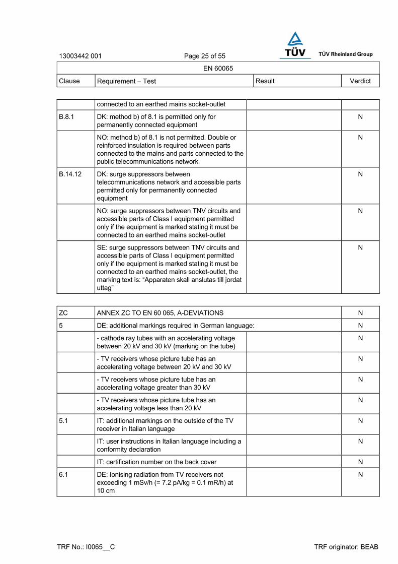
connected to an earthed mains socket-outlet
B.8.1 DK: method b) of 8.1 is permitted only for permanently connected equipment
N
NO: method b) of 8.1 is not permitted. Double or reinforced insulation is required between parts connected to the mains and parts connected to the public telecommunications network
N
B.14.12 DK: surge suppressors between telecommunications network and accessible parts permitted only for permanently connected equipment
N
NO: surge suppressors between TNV circuits and accessible parts of Class I equipment permitted only if the equipment is marked stating it must be connected to an earthed mains socket-outlet
N
SE: surge suppressors between TNV circuits and accessible parts of Class I equipment permitted only if the equipment is marked stating it must be connected to an earthed mains socket-outlet, the marking text is: “Apparaten skall anslutas till jordat uttag”
N
ZC ANNEX ZC TO EN 60 065, A-DEVIATIONS N
5 DE: additional markings required in German language: N
- cathode ray tubes with an accelerating voltage between 20 kV and 30 kV (marking on the tube)
N
- TV receivers whose picture tube has an accelerating voltage between 20 kV and 30 kV
N
- TV receivers whose picture tube has an accelerating voltage greater than 30 kV
N
- TV receivers whose picture tube has an accelerating voltage less than 20 kV
N
5.1 IT: additional markings on the outside of the TV receiver in Italian language
N
IT: user instructions in Italian language including a conformity declaration
N
IT: certification number on the back cover N
6.1 DE: Ionising radiation from TV receivers not exceeding 1 mSv/h (= 7.2 pA/kg = 0.1 mR/h) at 10 cm
N

13003442 001 Page 26 of 55
EN 60065
Clause Requirement − Test Result Verdict
TRF No.: I0065__C TRF originator: BEAB
7.1 TABLE: temperature rise measurements P
Power consumption in the OFF/Stand-by —
Position of the functional switch (W) ...................... : —
Un (V) In (A) Pn (W) Pout (W)
Operating conditions: stand-by mode for Samsung panel
90V 50 Hz 70.1 mA 2.5 W -
100V 50 Hz 62.2 mA 2.3 W -
240V 50 Hz 73.8 mA 2.5 W -
254V 50 Hz 75.9 mA 2.6 W -
90V 60 Hz 65.2 mA 2.5 W -
100V 60 Hz 58.5 mA 2.3 W -
240V 60 Hz 62.3 mA 2.4 W -
254V 60 Hz 65.2 mA 2.6 W -
Operating conditions: DVD mode for Samsung panel
90V 50 Hz 1.162 A 104.4 W -
100V 50 Hz 1.037 A 103.7 W -
240V 50 Hz 0.494 A 102.5 W -
254V 50 Hz 0.499 A 101.9 W -
90V 60 Hz 1.148 A 103.5 W -
100V 60 Hz 1.033 A 103.2 W -
240V 60 Hz 0.495 A 102.2 W -
254V 60 Hz 0.498 A 101.5 W -
Operating conditions: TV mode for Samsung panel
90V 50 Hz 1.179 A 105.9 W -
100V 50 Hz 1.053 A 105.3 W -
240V 50 Hz 0.498 A 103.8 W -
254V 50 Hz 0.503 A 103.5 W -
90V 60 Hz 1.170 A 105.4 W -
100V 60 Hz 1.051 A 104.8 W -
240V 60 Hz 0.499 A 103.5 W -
254V 60 Hz 0.502 A 103.2 W -
13003442 001 Page 27 of 55
EN 60065
Clause Requirement − Test Result Verdict
TRF No.: I0065__C TRF originator: BEAB
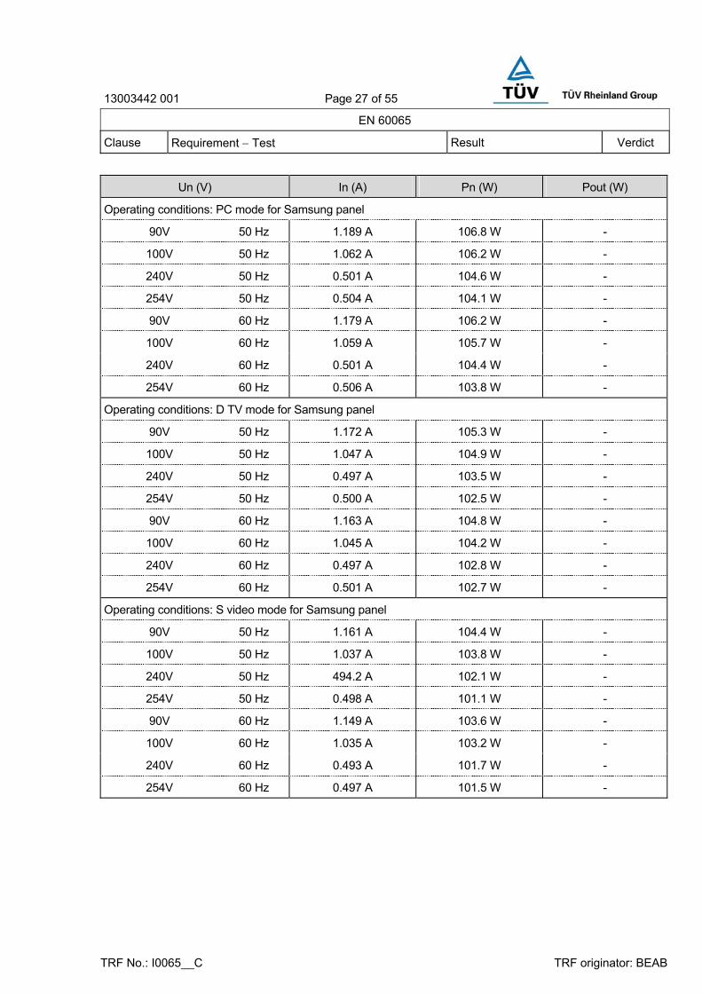
Un (V) In (A) Pn (W) Pout (W)
Operating conditions: PC mode for Samsung panel
90V 50 Hz 1.189 A 106.8 W -
100V 50 Hz 1.062 A 106.2 W -
240V 50 Hz 0.501 A 104.6 W -
254V 50 Hz 0.504 A 104.1 W -
90V 60 Hz 1.179 A 106.2 W -
100V 60 Hz 1.059 A 105.7 W -
240V 60 Hz 0.501 A 104.4 W -
254V 60 Hz 0.506 A 103.8 W -
Operating conditions: D TV mode for Samsung panel
90V 50 Hz 1.172 A 105.3 W -
100V 50 Hz 1.047 A 104.9 W -
240V 50 Hz 0.497 A 103.5 W -
254V 50 Hz 0.500 A 102.5 W -
90V 60 Hz 1.163 A 104.8 W -
100V 60 Hz 1.045 A 104.2 W -
240V 60 Hz 0.497 A 102.8 W -
254V 60 Hz 0.501 A 102.7 W -
Operating conditions: S video mode for Samsung panel
90V 50 Hz 1.161 A 104.4 W -
100V 50 Hz 1.037 A 103.8 W -
240V 50 Hz 494.2 A 102.1 W -
254V 50 Hz 0.498 A 101.1 W -
90V 60 Hz 1.149 A 103.6 W -
100V 60 Hz 1.035 A 103.2 W -
240V 60 Hz 0.493 A 101.7 W -
254V 60 Hz 0.497 A 101.5 W -
13003442 001 Page 28 of 55
EN 60065
Clause Requirement − Test Result Verdict
TRF No.: I0065__C TRF originator: BEAB
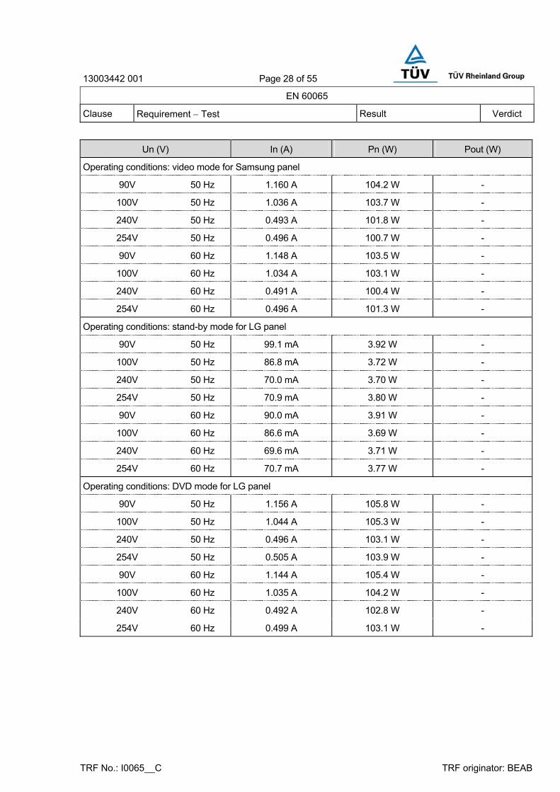
Un (V) In (A) Pn (W) Pout (W)
Operating conditions: video mode for Samsung panel
90V 50 Hz 1.160 A 104.2 W -
100V 50 Hz 1.036 A 103.7 W -
240V 50 Hz 0.493 A 101.8 W -
254V 50 Hz 0.496 A 100.7 W -
90V 60 Hz 1.148 A 103.5 W -
100V 60 Hz 1.034 A 103.1 W -
240V 60 Hz 0.491 A 100.4 W -
254V 60 Hz 0.496 A 101.3 W -
Operating conditions: stand-by mode for LG panel
90V 50 Hz 99.1 mA 3.92 W -
100V 50 Hz 86.8 mA 3.72 W -
240V 50 Hz 70.0 mA 3.70 W -
254V 50 Hz 70.9 mA 3.80 W -
90V 60 Hz 90.0 mA 3.91 W -
100V 60 Hz 86.6 mA 3.69 W -
240V 60 Hz 69.6 mA 3.71 W -
254V 60 Hz 70.7 mA 3.77 W -
Operating conditions: DVD mode for LG panel
90V 50 Hz 1.156 A 105.8 W -
100V 50 Hz 1.044 A 105.3 W -
240V 50 Hz 0.496 A 103.1 W -
254V 50 Hz 0.505 A 103.9 W -
90V 60 Hz 1.144 A 105.4 W -
100V 60 Hz 1.035 A 104.2 W -
240V 60 Hz 0.492 A 102.8 W -
254V 60 Hz 0.499 A 103.1 W -

13003442 001 Page 29 of 55
EN 60065
Clause Requirement − Test Result Verdict
TRF No.: I0065__C TRF originator: BEAB
Un (V) In (A) Pn (W) Pout (W)
Operating conditions: TV mode for LG panel
90V 50 Hz 1.147 A 103.8 W -
100V 50 Hz 1.024 A 102.8 W -
240V 50 Hz 491.2 A 101.1 W -
254V 50 Hz 0.498 A 101.5 W -
90V 60 Hz 1.135 A 102.6 W -
100V 60 Hz 1.025 A 102.4 W -
240V 60 Hz 0.461 A 101.1 W -
254V 60 Hz 0.491 A 102.3 W -
Operating conditions: PC mode for LG panel
90V 50 Hz 1.124 A 101.3 W -
100V 50 Hz 1.017 A 101.2 W -
240V 50 Hz 0.489 A 100.4 W -
254V 50 Hz 0.496 A 99.8 W -
90V 60 Hz 1.109 A 100.8 W -
100V 60 Hz 1.003 A 101.1 W -
240V 60 Hz 0.472 A 100.1 W -
254V 60 Hz 0.485 A 101.0 W -
Operating conditions: D TV mode for LG panel
90V 50 Hz 1.120 A 100.7 W -
100V 50 Hz 1.005 A 99.9 W -
240V 50 Hz 0.486 A 99.8 W -
254V 50 Hz 0.491 A 98.1 W -
90V 60 Hz 1.088 A 99.1 W -
100V 60 Hz 0.991 A 98.9 W -
240V 60 Hz 0.469 A 99.1 W -
254V 60 Hz 0.484 A 100.1 W -

13003442 001 Page 30 of 55
EN 60065
Clause Requirement − Test Result Verdict
TRF No.: I0065__C TRF originator: BEAB
Un (V) In (A) Pn (W) Pout (W)
Operating conditions: S video mode for LG panel
90V 50 Hz 1.110 A 100.4 W -
100V 50 Hz 0.998 A 99.6 W -
240V 50 Hz 0.483 A 97.5 W -
254V 50 Hz 0.490 A 97.6 W -
90V 60 Hz 1.082 A 98.7 W -
100V 60 Hz 0.983 A 97.2 W -
240V 60 Hz 0.461 A 98.5 W -
254V 60 Hz 0.481 A 99.5 W -
Operating conditions: video mode for LG panel
90V 50 Hz 1.102 A 99.6 W -
100V 50 Hz 0.996 A 98.8 W -
240V 50 Hz 0.481 A 97.2 W -
254V 50 Hz 0.487 A 96.8 W -
90V 60 Hz 1.080 A 98.1 W -
100V 60 Hz 0.980 A 96.9 W -
240V 60 Hz 0.458 A 97.6 W -
254V 60 Hz 0.481 A 99.5 W -

13003442 001 Page 31 of 55
EN 60065
Clause Requirement − Test Result Verdict
TRF No.: I0065__C TRF originator: BEAB
monitored point 90Vac dT (K) PC mode
254Vac dT (K) PC mode
254Vac dT (K) blocked opening
required dT (K)
Power switch body 2.3 2.3 2.2 60 / 65
Inlet body 6.1 5.8 9.5 - / -
L802 coil 25.9 15.3 32.6 85 / 150
L804 coil 21.3 12.7 25.4 85 / 150
D801 body 42.3 26.3 48.1 - / -
L805 coil 54.8 35.7 59.3 85 / 150
L805 core 47.7 31.8 52.5 85 / 150
C807 body 23.1 21 27 105 °C
IC804 case 23.2 22.3 29.6 - / -
T801 coil 37.1 37.1 41.6 85 / 150
T801 core 31.1 30.8 35.5 85 / 150
Inverter transformer (T16) coil 34.9 34.3 41.7 85 / 150
Inverter transformer (T16) core 31.4 30.2 39.3 85 / 150
C260 body 32.7 32.9 39.7 125 °C
Heat sink of Q603 25 23.9 33.7 - / -
Q601 body 34.5 33.3 47.4 - / -
Tuner case 17.3 17.2 21.7 40 / 65
LCD front surface 20.9 21.6 23.4 60 / 65
Rear plastic enclosure 12.1 12.1 22.4 60 / 65
P802 15.2 15.1 26.3 - / -
Ambient 23.8°C 23.1°C 24.1°C - / -
Winding temperature rise measurements N
Ambient temperature t1 (°C) .................................. : —
Ambient temperature t2 (°C) .................................. : —
temperature rise dT of winding: R1 (W) R2 (W) dT (K) required dT (K)
insulation class

13003442 001 Page 32 of 55
EN 60065
Clause Requirement − Test Result Verdict
TRF No.: I0065__C TRF originator: BEAB
7.2 TABLE: softening temperature of thermoplastics P
temperature T of part T - normal conditions (°C)
T - fault conditions (°C)
T softening
(°C)
Bobbin of Transformer (T801) 60.9 65.7 211.5
Bobbin of Line Filter (L802) 49.7 56.7 160.1
Bobbin of Line Filter (L804) 45.1 49.5 160.1
Bobbin of PFC (L805) 78.6 83.4 184.2
Appliance inlet 29.9 33.6 184.2
P802 male/female 39.0 50.4 185.1
10.3 TABLE: insulation resistance measurements P
insulation resistance R between: R (MΩ) required R (MΩ)
LCD TV after heating test
Primary – Tuner with secondary part > 100MΩ 4MΩ
Primary – Earth part > 100MΩ 2MΩ
LCD TV after humidity test
Primary – Tuner with secondary part > 100MΩ 4MΩ
Primary – Earth part > 100MΩ 2MΩ
LCD TV after surge test
Primary – Tuner with secondary part > 100MΩ 4MΩ
Primary – Earth part > 100MΩ 2MΩ
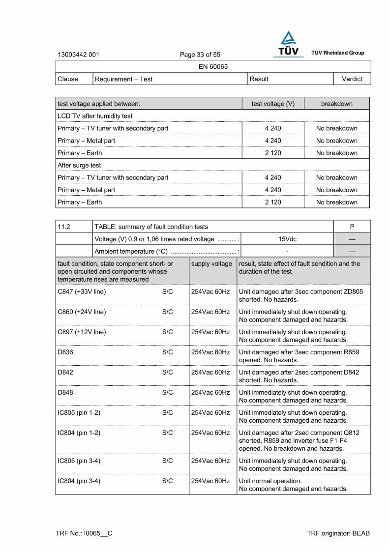
10.3 TABLE: electric strength measurements P
test voltage applied between: test voltage (V) breakdown
LCD TV after heating test
Primary – TV tuner with secondary part 4 240 No breakdown
Primary – Metal part 4 240 No breakdown
Primary – Earth 2 120 No breakdown
Transformer; Primary – Secondary 4 240 No breakdown
Primary – Core 2 120 No breakdown
Secondary – Core 2 120 No breakdown
13003442 001 Page 33 of 55
EN 60065
Clause Requirement − Test Result Verdict
TRF No.: I0065__C TRF originator: BEAB
test voltage applied between: test voltage (V) breakdown
LCD TV after humidity test
Primary – TV tuner with secondary part 4 240 No breakdown
Primary – Metal part 4 240 No breakdown
Primary – Earth 2 120 No breakdown
After surge test
Primary – TV tuner with secondary part 4 240 No breakdown
Primary – Metal part 4 240 No breakdown
Primary – Earth 2 120 No breakdown
11.2 TABLE: summary of fault condition tests P
Voltage (V) 0,9 or 1,06 times rated voltage ........... : 15Vdc —
Ambient temperature (°C) ...................................... : - —
fault condition, state component short- or open circuited and components whose temperature rises are measured
supply voltage result, state effect of fault condition and the duration of the test
C847 (+33V line) S/C 254Vac 60Hz Unit damaged after 3sec component ZD805 shorted. No hazards.
C860 (+24V line) S/C 254Vac 60Hz Unit immediately shut down operating. No component damaged and hazards.
C897 (+12V line) S/C 254Vac 60Hz Unit immediately shut down operating. No component damaged and hazards.
D836 S/C 254Vac 60Hz Unit damaged after 3sec component R859 opened. No hazards.
D842 S/C 254Vac 60Hz Unit damaged after 2sec component D842 shorted. No hazards.
D848 S/C 254Vac 60Hz Unit immediately shut down operating. No component damaged and hazards.
IC805 (pin 1-2) S/C 254Vac 60Hz Unit immediately shut down operating. No component damaged and hazards.
IC804 (pin 1-2) S/C 254Vac 60Hz Unit damaged after 2sec component Q812 shorted, R859 and inverter fuse F1-F4 opened. No breakdown and hazards.
IC805 (pin 3-4) S/C 254Vac 60Hz Unit immediately shut down operating. No component damaged and hazards.
IC804 (pin 3-4) S/C 254Vac 60Hz Unit normal operation. No component damaged and hazards.

13003442 001 Page 34 of 55
EN 60065
Clause Requirement − Test Result Verdict
TRF No.: I0065__C TRF originator: BEAB
fault condition, state component short- or open circuited and components whose temperature rises are measured
supply voltage result, state effect of fault condition and the duration of the test
D803 S/C 254Vac 60Hz Unit immediately damaged D801, Q808 shorted and R806, F801 opened. No hazards.
Q815 (S-D) S/C 254Vac 60Hz Unit immediately damaged Q805, Q817 shorted. No hazards.
Q815 (D-G) S/C 254Vac 60Hz Unit damaged after 10min component R835 opened. No hazards.
Q816 (S-D) S/C 254Vac 60Hz Unit normal operation. No component damaged and hazards.
Q816 (D-G) S/C 254Vac 60Hz Unit damaged after 30sec component R835 opened. No hazards.
Q808 (D-S) S/C 254Vac 60Hz Unit immediately damaged Q808, IC801, D801 shorted and F801 opened. No hazards.
Q808 (D-G) S/C 254Vac 60Hz Unit immediately damaged Q808, IC801, D801 shorted and F801 opened. No hazards.
IC801 (1-8) S/C 254Vac 60Hz Unit immediately damaged Q808, IC801, D801 shorted and F801 opened. No hazards.
IC801 (1-6) S/C 254Vac 60Hz Unit normal operation. No component damaged and hazards.
IC801 (1-5) S/C 254Vac 60Hz Unit normal operation. No component damaged and hazards.
IC803 (23-7) S/C 254Vac 60Hz Unit immediately damaged IC803 shorted and F801 opened. No hazards.
IC803 (23-10) S/C 254Vac 60Hz Unit immediately damaged D811, IC803, Q808 shorted and F801 opened. No hazards.
IC803 (23-15) S/C 254Vac 60Hz Unit immediately damaged Q810, Q811, Q808, IC803 shorted and R830, F801 opened. No hazards.
C840 S/C 254Vac 60Hz Unit immediately damaged D801 shorted and F801 opened. No hazards.
D801 (Live, +) S/C 254Vac 60Hz Unit immediately F801 opened. No hazards.
D801 (Neutral, - ) S/C 254Vac 60Hz Unit immediately F801 opened. No hazards.
Blocked opening AB 254Vac/50Hz Temperature stabilized at T801 coil 65.7°C, L802 coil 56.7°C, L804 coil 49.5°C, L805 coil 83.4°C and inverter transformer (T16) 65.8. No hazards.
I.P. ; internal protection. AB; abnormal test
13003442 001 Page 35 of 55
EN 60065
Clause Requirement − Test Result Verdict
TRF No.: I0065__C TRF originator: BEAB
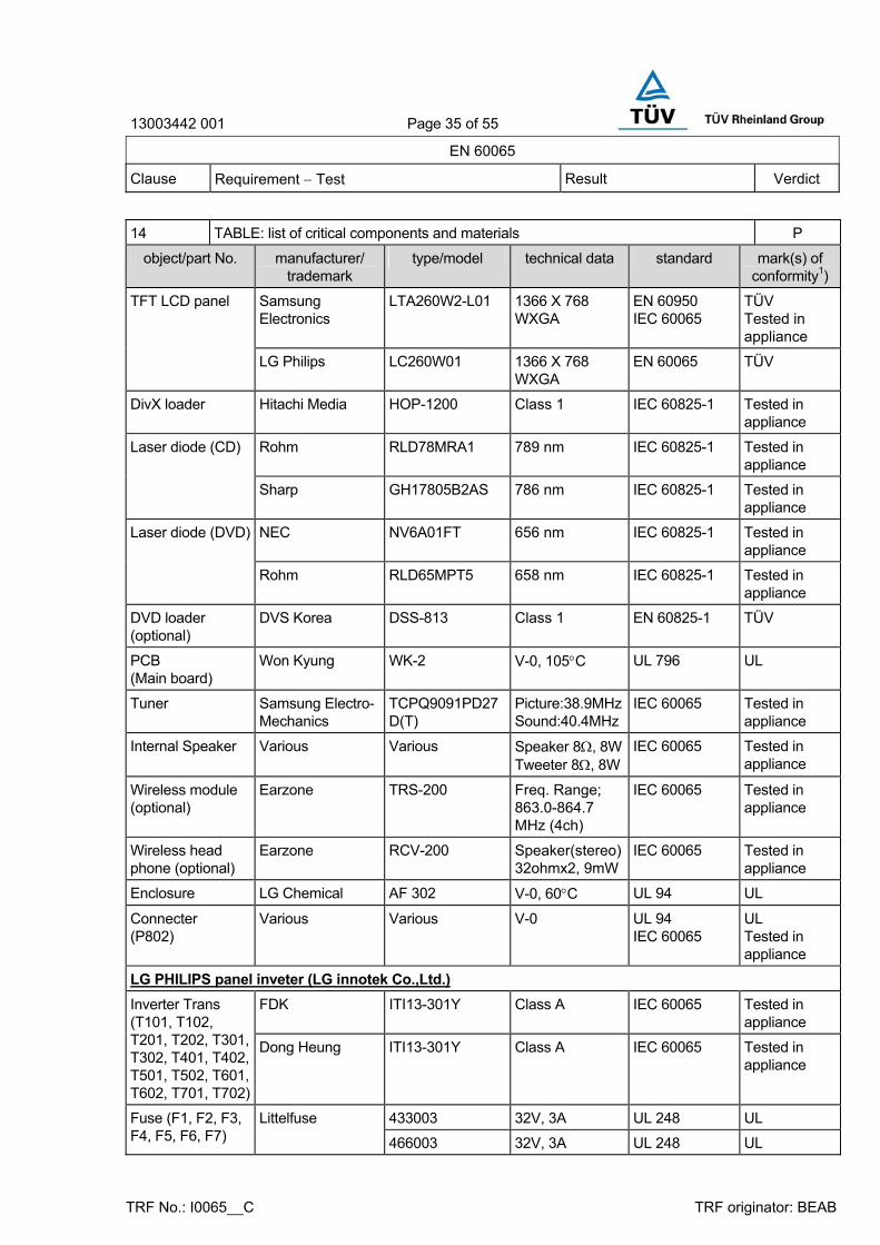
14 TABLE: list of critical components and materials P
object/part No. manufacturer/ trademark
type/model technical data standard mark(s) of conformity1)
Samsung Electronics
LTA260W2-L01 1366 X 768 WXGA
EN 60950 IEC 60065
TÜV Tested in appliance
TFT LCD panel
LG Philips LC260W01 1366 X 768 WXGA
EN 60065 TÜV
DivX loader Hitachi Media HOP-1200 Class 1 IEC 60825-1 Tested in appliance
Rohm RLD78MRA1 789 nm IEC 60825-1 Tested in appliance
Laser diode (CD)
Sharp GH17805B2AS 786 nm IEC 60825-1 Tested in appliance
NEC NV6A01FT 656 nm IEC 60825-1 Tested in appliance
Laser diode (DVD)
Rohm RLD65MPT5 658 nm IEC 60825-1 Tested in appliance
DVD loader (optional)
DVS Korea DSS-813 Class 1 EN 60825-1 TÜV
PCB (Main board)
Won Kyung WK-2 V-0, 105°C UL 796 UL
Tuner Samsung Electro-Mechanics
TCPQ9091PD27D(T)
Picture:38.9MHzSound:40.4MHz
IEC 60065 Tested in appliance
Internal Speaker Various Various Speaker 8Ω, 8WTweeter 8Ω, 8W
IEC 60065 Tested in appliance
Wireless module (optional)
Earzone TRS-200 Freq. Range; 863.0-864.7 MHz (4ch)
IEC 60065 Tested in appliance
Wireless head phone (optional)
Earzone RCV-200 Speaker(stereo)32ohmx2, 9mW
IEC 60065 Tested in appliance
Enclosure LG Chemical AF 302 V-0, 60°C UL 94 UL
Connecter (P802)
Various Various V-0 UL 94 IEC 60065
UL Tested in appliance
LG PHILIPS panel inveter (LG innotek Co.,Ltd.) FDK ITI13-301Y Class A IEC 60065 Tested in
appliance Inverter Trans (T101, T102, T201, T202, T301, T302, T401, T402, T501, T502, T601, T602, T701, T702)
Dong Heung ITI13-301Y Class A IEC 60065 Tested in appliance
433003 32V, 3A UL 248 UL Fuse (F1, F2, F3, F4, F5, F6, F7)
Littelfuse
466003 32V, 3A UL 248 UL

13003442 001 Page 36 of 55
EN 60065
Clause Requirement − Test Result Verdict
TRF No.: I0065__C TRF originator: BEAB
object/part No. manufacturer/ trademark
type/model technical data standard mark(s) of conformity1)
Woo Sung WS-5 V-0. 105°C UL 796 UL
Sam Woo SW3 V-0. 105°C UL 796 UL
PCB
Korea Circuit KS-11C V-0. 105°C UL 796 UL
LG PHILIPS panel inveter (Korea Taiyo Yuden Co.,Ltd.)
Inverter Trans (T201, T202, T301, T302, T401, T402, T501, T502, T601, T602, T701, T702, T801, T802)
FDK CD-T-1332-676 Class A IEC 60065 Tested in appliance
433003 32V, 3A UL 248 UL Fuse (F2, F3, F4, F5, F6, F7, F8)
Littelfuse
466003 32V, 3A UL 248 UL
KIPS Elec. 5 V-0. 105°C UL 796 UL PCB
Ki Joo KJ8-V-0 V-0. 105°C UL 796 UL
Samsung panel inveter (Hansol LCD Inc.)
Inverter Trans (T1, T2, T3, T4, T5, T6, T7, T8)
Nam yang Electronics
HU24W2AA Class A IEC 60065 Tested in appliance
Inverter Trans (T9, T10, T11, T12, T13, T14, T15, T16)
Nam yang Electronics
HU24W2AB Class A IEC 60065 Tested in appliance
433003 32V, 3A UL 248 UL Fuse Littelfuse
466003 32V, 3A UL 248 UL
PCB Shanghai Nanya Copper clad Laminates
SN-L3 or SN-L4 V-0, 130°C UL 796 UL
Alternate Global Circuit GC3V0 V-0, 130°C UL 796 UL
SMPS (Manufacturer: H & E Co.,Ltd)
Appliance inlet I Sheng 7001 250V, 10A IEC 60320 VDE
Switch Chily Precision Industrial
Type 3024... 250V, 16A DIN EN 61058 VDE
Littelfuse 215 250V, 5A IEC 60127 VDE Fuse (F801)
Bussmann Cooper (U.K) Ltd.
S505 250V, 5A IEC 60127 VDE
X-capacitor (C845)
Pilkor PCX2 337 275Vac, 0.33uF IEC 60384-14-2nd
VDE

13003442 001 Page 37 of 55
EN 60065
Clause Requirement − Test Result Verdict
TRF No.: I0065__C TRF originator: BEAB
object/part No. manufacturer/ trademark
type/model technical data standard mark(s) of conformity1)
X-capacitor (C805, C808)
Pilkor PCX2 337 275Vac, 0.22uF IEC 60384-14-2nd
VDE
Sam Wha SD 250V, 1000pF Y1
IEC 60384-14-2nd
VDE Y-capacitor (C803, C846)
Dong Il DA 250V, 1000pF Y1
IEC 60384-14-2nd
VDE
Sam Wha SD 250V, 1000pF Y1
IEC 60384-14-2nd
VDE Bridging capacitor (C806)
Dong Il DA 250V, 1000pF Y1
IEC 60384-14-2nd
VDE
Smart Electronics PRC 0.47M ohm, 1/2W
BS EN 60065 BSI Discharge Resistor (R802)
Pilkor MSR 0.47M ohm, 1/2W
DIN EN 60065 VDE
Smart Electronics PRC 10M ohm, 1/2W BS EN 60065 BSI Insulation Resistor (R803)
Pilkor MSR 10M ohm, 1/2W DIN EN 60065 VDE
Sam wha SVC621D-14A 680V CECC 42200 VDE
Il Jin Electornics INR 14D 621 680V CECC 42200 VDE
Varistor (VA801)
Amotech INR 14D 621 680V CECC 42200 VDE
DSC DSC 5D-15 5ohm at 25°C UL 1434 IEC 60065
UL Tested in appliance
Thermister (TH802)
Thermometrics TP 5D15 5ohm at 25°C UL 1434 IEC 60065
UL Tested in appliance
Lite-on LTV817 Isolation Volt.: min. 5000V > 0.4 mm
EN 60950 VDE Optocoupler (IC804, IC805)
Cosmo KP1010 Isolation Volt.: min. 5000V > 0.4 mm
EN 60950 VDE
Linefilter (L802 , L804)
KU-BONG elec. B62-FTR2022 Class E IEC 60065 Tested in appliance
Soo Jung B60-P3019A Class E IEC 60065 Tested in appliance
PFC coil (L805)
Nam Yang B60-P3019A Class E IEC 60065 Tested in appliance

13003442 001 Page 38 of 55
EN 60065
Clause Requirement − Test Result Verdict
TRF No.: I0065__C TRF originator: BEAB
object/part No. manufacturer/ trademark
type/model technical data standard mark(s) of conformity1)
Transformer (T801)
Soo Jung B60-T5050C Class E IEC 60065 Tested in appliance
Dong Myung Type 3 V-0, 130°C UL 796 UL PCB (power circuit)
Dae Sun Type 1 V-0, 130°C UL 796 UL
Electrolytic capacitor (C807)
Various Various 450V, 150uF, 105°C
IEC 60065 Tested in appliance
Bridge Diode (D801)
Various Various 600V, 4A IEC 60065 Tested in appliance
Australia power cord set
Main plug Kenic Electric Mfg. Co.,Ltd
KE-13 250V, 10A AS 3112 SAA
Main power supply cord
Kenic Electric Mfg. Co.,Ltd
H05VV-F 3G X 0.75mm2 IEC 60227 VDE
Main connector Kenic Electric Mfg. Co.,Ltd
KE-24 250V, 10A IEC 60320 AS 3109
VDE SAA
European power cord set (the exclusion of U.K.)
Main plug Korea KDK or Hwajin KDK
KKP-4819R 250V, 16A DIN VDE 0620 VDE
Main power supply cord
Korea KDK or Hwajin KDK
H05VV-F 3G X 0.75mm2 IEC 60227 VDE
Main connector Korea KDK or Hwajin KDK
KKS-16A 250V, 10A IEC 60320 VDE
Alternate cord set
Main plug Longwell LP-33 250V, 16A DIN VDE 0620 VDE
Main power supply cord
Longwell H05VV-F 3G X 0.75mm2 IEC 60227 VDE
Main connector Longwell LS-60 250V, 10A IEC 60320 VDE
Alternate cord set
Main plug Wanshun electrical
WS-02 250V, 16 DIN VDE 0620 VDE
Main power supply cord
Leader Electric wire&cable co.,ltd
HO5VV-F 3G X 0.75mm2 IEC 60227 VDE
Main connector Wanshun electrical
WS-003 250V, 10A UL 94 IEC 60065
UL Tested in appliance

13003442 001 Page 39 of 55
EN 60065
Clause Requirement − Test Result Verdict
TRF No.: I0065__C TRF originator: BEAB
object/part No. manufacturer/ trademark
type/model technical data standard mark(s) of conformity1)
U.K. type power cord set
Main plug Korea KDK or Hwajin KDK
KKP-650 250V, 5A BS 1363 BSI
Main power supply cord
Korea KDK or Hwajin KDK
H05VV-F or KOCE-3
3G X 0.75mm2 IEC 60227 KEMA
Main connector Korea KDK or Hwajin KDK
KKS-16A 250V, 10A BS 1363 BSI
Alternate cord set
Main plug Hangzhou fuxinig electrical limited.
SW-168 250V, 5A BS 1363 BSI
Main power supply cord
Leader Electric wire&cable co.,ltd
HO5VV-F 3G X 0.75mm2 IEC 60227 VDE
Main connector Wanshun electrical
WS-003 250V, 10A UL 94 IEC 60065
UL Tested in appliance
1) an asterisk indicates a mark which assures the agreed level of surveillance. 2) Provided to inside of top enclosure; 50 by 50 mm, min. 0.4 mm tick.

13003442 001 Page 40 of 55
National Difference
Clause Requirement – Test Result - Remark Verdict
CENELEC common modifications (Group differences) and Special national conditions according to CB Bulletin No. 105A, May 2003
APPENDIX CENELEC common modifications (Group differences) and Special national conditions according to CB Bulletin No. 105A, May 2003
P
EXPLANATION FOR ABBREVIATIONS
C=CENELEC common modification, S=Special national condition
P=Pass, F=Fail, N=Not applicable. Placed in the column to the right.
1.1.1 C Replace the text of note 1 by:
NOTE 1 This standard can be used as a guide for the testing of battery operated apparatus.
P
2.6.1 S Denmark
The following is added:
Certain types of Class I apparatus, see Sub-clause 15.1.1, may be provided with a plug not establishing earthing continuity when inserted in Danish socket-outlets.
Justification:
Heavy Current Regulations, Section 107
N
3.1 C Delete the note.
Add the following indent:
- Exposure to excessive sound pressures from headphones or earphones.
NOTE A new method is under consideration by CENELEC/TC 206.
N
5.1 S Italy
The following requirements shall be fulfilled:
The power consumption in Watts (W) shall be indicated on TV receivers (Measurement according to EN 60555-2)
TV receivers shall be provided with an instruction for use, schematic diagrams and adjustments procedure in Italian language.
Marking for controls and terminals shall be in Italian language. Abbreviation and international symbols are allowed provided that they are explained in the instruction for use.
The EEC manufacturers are bound to issue a conformity declaration according to the above requirements in the instruction manual. The correct
N

13003442 001 Page 41 of 55
National Difference
Clause Requirement – Test Result - Remark Verdict
CENELEC common modifications (Group differences) and Special national conditions according to CB Bulletin No. 105A, May 2003
statement for conformity to be written in the instruction manual, shall be: Questo apparecchio è fabbricato nella CEE nel rispetto delle disposizioni del D.M. marzo 1992 ed è in particolare conforme alle prescrizioni dell’art. 1 dello stesso D.M.
The first importers of TV receivers manufactured outside EEC are bound to submit the TV receivers for previous conformity certification to the Italian Post Ministry (PP.TT).
The TV receivers shall have on the backcover the certification number assigned by the Italian Post Ministry in the following form:
D.M. 26/03/1992 xxxxx/xxxxx/S or T or pT S for stereo
T for teletext
pT for retrofitable teletext
Justification:
Ministerial Decree of 26 March 1992: National rules for television receivers trade.
15.1.1 C Delete note 1 and 2.
Add to note 4.
Attention is drawn to the fact that a standard is under preparation (presently prEN 50074) for socket-outlets which allow connection of Class II appliances only.
N

13003442 001 Page 42 of 55
National Difference
Clause Requirement – Test Result - Remark Verdict
CENELEC common modifications (Group differences) and Special national conditions according to CB Bulletin No. 105A, May 2003
15.1.1 S Denmark
To the first paragraph the following is added:
In Denmark, supply cords of a single phase appliance having a rated current not exceeding 10A shall be provided with a plug according to the Heavy Current Regulations Section 107-2-D1.
Appliance of class I provided with socket-outlets with earth contact or which are intended to be used in locations where against indirect contact is required according to the wiring rules shall be provided with a plug in accordance with standard sheet DK 2-1a.
To the second paragraph the following is added:
Socket outlets intended for provision power to Class II apparatus with a rated current of 2,5A shall have the following dimensions:
Other Dimensions shall be according to IEC 60083, Standard Sheet C 1a for portable socket-outlets.
NOTE This Special National Condition will be deleted when prEN 50074 is ratified.
To the third paragraph the following is added:
Mains socket-outlets with earthing contact shall be in compliance with Heavy Current Regulations Section 107-2-D1, Standard sheet DK 1-3a, DK 1-5a or DK 1-7a.
Justification:
Heavy Current Regulations, Section 107.
N

13003442 001 Page 43 of 55
National Difference
Clause Requirement – Test Result - Remark Verdict
CENELEC common modifications (Group differences) and Special national conditions according to CB Bulletin No. 105A, May 2003
15.1.1 S Norway
Mains socket-outlets mounted on Class II apparatus shall comply with the specifications given in CEE Publ. 7 as far as applicable, with the following amendments:
§ 8 Dimensions
A 2.5A, 250V two-pole socket-outlets for electronic apparatus shall comply with the enclosed Standard Sheet I.
§ 24 Mechanical strength
A 2.5A, 250V socket-outlets for Class II electronic apparatus are tested as specified in EN 60065, Subclause 12.1.3. Also the protecting rim shall be tested.
Justification:
Act of 24 May 1929 relating to supervision of electrical installation (TEA 1929/FEB 1991).
NOTE This Special National Condition will be deleted when prEN 50074 is ratified.
N
15.1.1 S United Kingdom
Apparatus which is fitted with a flexible cable or cord and is designed to be connected to a mains socket conforming to BS 1363 by means of that flexible cable or cord and plug shall be fitted with a “standard plug” in accordance with Statutory Instrument 1768:1994: The Plugs and Sockets etc. (Safety) Regulations 1994, unless exempted by those Regulations.
NOTE “Standard plug” is defied in SI 1768:1994 and essentially means an approved plug conforming to BS 1363 or an approved conversion plug.
Justification:
SI 1768:1994
N
15.2 C Delete note 2. N
16.1 C Delete note 1. N
16.2 C Delete the note. N
20 C Delete note 2. N
Annex B C Delete note 2. N
B.5.4.1 e) C
Delete note 1 and 2. N

13003442 001 Page 44 of 55
National Difference
Clause Requirement – Test Result - Remark Verdict
CENELEC common modifications (Group differences) and Special national conditions according to CB Bulletin No. 105A, May 2003
B.5.4.1 e) S
Norway
The following note is added:
NOTE In Norway, if separation between the MAINS and a telecommunication system/network, other than public TELECOMMUNICATION NETWORKS, relies upon connection to the safety earth, apparatus shall have a marking stating that it must be connected to an earthed mains socket-outlet.
For requirements for the apparatus to be connected to public TELECOMMUNICATION NETWORK, see B.8.1.
Justification:
Based on a use in Norway of an IT power distribution system where the neutral is not provided and where wall socket-outlets without earth are used in parts of building installations.
N
B.5.4.1 e) S
Sweden
The following note is added:
NOTE In Sweden, if – for apparatus to be connected to the MAINS by means of a plug – the separation between the MAINS and the TELECOMMUNICATION NETWORKS relies upon connection to protective earth, the apparatus shall have a marking stating that it must be connected to an earthed MAINS socket-outlet.
The marking text shall be in Swedish and as follows: “Apparaten skall anslutas till jordat uttag.”
Justification:
In Sweden, unearthed wall socket-outlets exist in many building installation all over the country.
N
B.8.1 C Delete note 1, 2 and 3. N
B.8.1 S Denmark
The following note is added:
NOTE In Denmark method b) is permitted only for PERMANENTLY CONNECTED APPARATUS.
Justification:
Heavy Current Regulations, Section 107.
N

13003442 001 Page 45 of 55
National Difference
Clause Requirement – Test Result - Remark Verdict
CENELEC common modifications (Group differences) and Special national conditions according to CB Bulletin No. 105A, May 2003
B.8.1 S Norway
The following note is added:
NOTE In Norway, method b) is not permitted. Insulation between parts CONDUCTIVELY CONNECTED TO THE MAINS and parts connected to a public TELECOMMUNICATION NETWORK shall comply with the requirements for DOUBLE or REINFORCED INSULATION.
Justification:
Based on a use in Norway of an IT power distribution system where the neutral is not provided and where wall socket-outlets without earth are used in parts of building installations.
N
B.8.2 C Delete the note. N
B.14.12 C Delete note 1 and 2. N
B.14.12 S Denmark
The following note is added:
NOTE In Denmark the use of surge suppressors between the TELECOMMUNICATION NETWORK and conductive ACCESSIBLE parts or TERMINALS which are considered to be ACCESSIBLE, is allowed only for PERMANENTLY CONNECTED APPARATUS.
Justification:
Heavy Current Regulations, Section 107.
N
B.14.2 S Norway
The following note is added:
NOTE In Norway, for Class I apparatus intended to be connected to the MAINS by means of a plug, surge suppressors may only be connected between TNV circuits and ACCESSIBLE parts if the apparatus has a marking stating that it must be connected to an earthed MAINS socket-outlet.
Justification:
Based on a use in Norway of an IT power distribution system where the neutral is not provided and where wall socket-outlets without earth are used in parts of building installations.
N

13003442 001 Page 46 of 55
National Difference
Clause Requirement – Test Result - Remark Verdict
CENELEC common modifications (Group differences) and Special national conditions according to CB Bulletin No. 105A, May 2003
B.14.2 S Sweden
The following note is added:
NOTE In Norway, for Class I apparatus intended to be connected to the MAINS by means of a plug, surge suppressors may only be connected between TNV circuits and ACCESSIBLE parts if the apparatus has a marking stating that it must be connected to an earthed MAINS socket-outlet.
The marking text shall be in Swedish and as follows: “Apparaten skall anslutas till jordat uttag.”
Justification:
In Sweden, unearthed wall socket-outlets exist in many building installation all over the country.
N
Annex G Delete the note. N
Annex P Bibliography
Add the following notes for the standards indicated:
IEC 60130 NOTE: IEC 60130-9:1989 + A1: 1993 are harmonized as EN 60130-9 (not modified).
IEC 60169 NOTE: Parts 23, 24 and 25 are harmonized as Ens (mot modified).
IEC 60173 NOTE: Harmonized as HD 27 S1: 1983 (not modified).
IEC 60260 NOTE: Haemonized as HD 98 S1: 1977 (not modified).
IEC 60335-2-56 NOTE: Harmonized as HD 60335-2- 56: 1997 (not modified).
IEC 61040 NOTE: Harmonized as EN 61040: 1992 (not modified).
IEC 60695 NOTE: Harmonized as EN 60695 series (not modified)
P

Page 47 of 55
TRF No.: IEC60825_1C TRF originator: UL
TEST REPORT EN 60825-1
Safety of laser products Part 1: Equipment classification, requirements and user’s guide
Section two: Manufacturing requirements Report reference No................ 13003442 001
Tested by (printed name and signature) ................................ (see cover page)
Approved by (printed name and signature) ......................... (see cover page)
Date of issue .......................... (see cover page)
This report is based on a blank test report that was prepared by SGS Fimko Ltd using information obtained from the TRF originator (see below)
CB Testing Laboratory name .. (see cover page)
Address ................................... (see cover page)
Testing location ....................... (see cover page)
Address ................................... (see cover page)
Applicant’s name .................... (see cover page)
Address ................................... (see cover page)
Test specification
Standard.................................. EN 60825-1:1994 + A1 + A2
Test procedure ....................... CCA-scheme
Non-standard test method ...... N.A.
Test Report Form No. ............. IEC60825_1C / 01-04
TRF originator . ....................... Underwriters Laboratories Inc.
Master TRF ............................ Dated 2001-04
Copyright © 2001 IEC System for Conformity Testing and Certification of Electrical Equipment (IECEE), Geneva, Switzerland. All rights reserved.
This publication may be reproduced in whole or in part for non-commercial purposes as long as the IECEE is acknowledged as copyright owner and source of the material. IECEE takes no responsibility for and will not assume liability for damages resulting from the reader's interpretation of the reproduced material due to its placement and context.
Test item description .............. (see cover page)
Trademark ............................... (see cover page)
Model and/or type reference ... (see cover page)
Rating(s) ................................. (see cover page)

13003442 001 Page 48 of 55
TRF No.: IEC60825_1C TRF originator: UL
Test item particulars (see cover page)
Equipment mobility .........................................: (see cover page)
Protection Class of equipment .......................: (see cover page)
Mass of equipment (kg)..................................: (see cover page)
Classification of laser product
Laser and/or LED product class of the equipment ......................................................:
Class 1 Laser Product (fault condition Class 1M Laser Product for DVD)
Laser and/or LED class of the radiation employed........................................................:
N/A
Maximum class of the embedded laser/LED (if an embedded laser/LED is employed)...........:
N/A
Test case verdicts
Test case does not apply to the test object ....: N/A
Test item does meet the requirement ............: P(ass)
Test item does not meet the requirement ......: F(ail)
Testing
Date of receipt of test item .............................: (see cover page)
Date(s) of performance of test .......................: (see cover page)
General remarks:
This test report is not valid as a CB Test Report unless signed by an approved CB Testing Laboratory and appended to a CB Test Certificate issued by an NCB in accordance with IECEE 02.
This report shall not be reproduced except in full without the written approval of the testing laboratory.
The test results presented in this report relate only to the item(s) tested.
“(see remark #)” refers to a remark appended to the report.
“(see Annex #)” refers to an annex appended to the report.
Throughout this report a point is used as the decimal separator.
General product information:
See EN 60950 report.
Copy of the Marking Plate and Warning Labels:
See EN 60950 report.

13003442 001 Page 49 of 55
EN 60825-1
Clause Requirement – Test Result - Remark Verdict
TRF No.: IEC60825_1C TRF originator: UL
4 ENGINEERING SPECIFICATIONS P
4.1 General remarks P
4.1.1 Modification Not modified product N
4.2 Protective housing P
4.2.1 General Laser does not exceed the limited of class 1 laser product under normal operation.
P
4.2.2 Service No service accessible necessary
P
4.2.3 Removable laser system Laser cannot be removed and operated without modification.
N
4.3 Access panels and safety interlocks N
4.3.1 Access panels of protective housing No protective housing N
4.3.2 Deliberate override mechanism No safety interlock required N
4.4 Remote interlock connector No remote interlock connector N
4.5 Key control No key control N
4.6 Laser radiation emission warning N
4.6.1 Audible or visible warning Class 1 emission level N
4.6.2 Operational control and laser aperture N
4.6.3 Laser emission distributed through more than one output
Single aperture N
4.7 Beam stop or attenuation Class 1 laser product N
4.8 Controls No controls N
4.9 Viewing optics No viewing optics provided N
a) human access to laser radiation in excess of Class 1M prevented when the shutter is opened or attenuation varied
N
b) opening of the shutter or variation of the attenuation prevented when exposure to laser radiation in excess of Class 1M is possible
N
4.10 Scanning safeguard No scanning N
4.11 Alignment aids Alignment of beam path not required
N
4.12 Walk-in access N
a). Means provided so that any person inside the housing can prevent activation of a Class 3B or 4 laser hazard
No “walk-in” access N

13003442 001 Page 50 of 55
EN 60825-1
Clause Requirement – Test Result - Remark Verdict
TRF No.: IEC60825_1C TRF originator: UL
b). A warning device provides adequate warning of emission to any person within the housing
No “walk-in” access N
4.13 Environmental conditions P
- climatic conditions Considered P
- vibration and shock Considered P
4.14 Protection against other hazards P
4.14.1 Non-optical hazards (see EN 60065 report) P
- electrical hazards; ―
- excessive temperature; ―
- spread of fire from the equipment; ―
- sound and ultrasonic; ―
- harmful substances; ―
- explosion; ―
4.14.2 Collateral radiation Collateral radiation not to be expected
N
5 LABELLING P
5.1 General P
LASER PRODUCT CLASS .........................................: Class 1 laser product P
5.2 – 5.6 Class 1 explanatory label provided on the product Class 1 laser product P
5.7 Aperture label .....................................................: Class 1 laser product N
5.8 Radiation output and standards information N
Maximum output of laser radiation .....................: See the appended table 1.5.1. ―
Pulse duration .....................................................: ―
Emitted wavelength(s) ........................................: See the appended table 1.5.1 ―
The name and publication date of the standard .: ―
5.9 Labels for access panels P
RADIATION CLASS ............................................: Class 1 P
5.9.1 Labels for panels P
Warning used.......................................................: ―
5.9.2 Labels for safety interlocked panels N
Warning used.......................................................: ―
5.10 Warning for invisible laser radiation ....................: N
5.11 Warning for visible laser radiation ......................: N
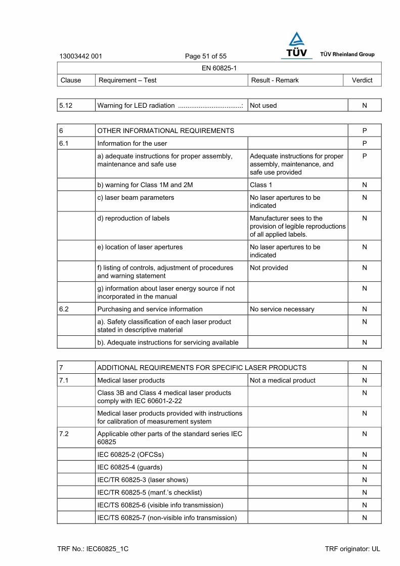
13003442 001 Page 51 of 55
EN 60825-1
Clause Requirement – Test Result - Remark Verdict
TRF No.: IEC60825_1C TRF originator: UL
5.12 Warning for LED radiation ..................................: Not used N
6 OTHER INFORMATIONAL REQUIREMENTS P
6.1 Information for the user P
a) adequate instructions for proper assembly, maintenance and safe use
Adequate instructions for proper assembly, maintenance, and safe use provided
P
b) warning for Class 1M and 2M Class 1 N
c) laser beam parameters No laser apertures to be indicated
N
d) reproduction of labels Manufacturer sees to the provision of legible reproductions of all applied labels.
N
e) location of laser apertures No laser apertures to be indicated
N
f) listing of controls, adjustment of procedures and warning statement
Not provided N
g) information about laser energy source if not incorporated in the manual
N
6.2 Purchasing and service information No service necessary N
a). Safety classification of each laser product stated in descriptive material
N
b). Adequate instructions for servicing available N
7 ADDITIONAL REQUIREMENTS FOR SPECIFIC LASER PRODUCTS N
7.1 Medical laser products Not a medical product N
Class 3B and Class 4 medical laser products comply with IEC 60601-2-22
N
Medical laser products provided with instructions for calibration of measurement system
N
7.2 Applicable other parts of the standard series IEC 60825
N
IEC 60825-2 (OFCSs) N
IEC 60825-4 (guards) N
IEC/TR 60825-3 (laser shows) N
IEC/TR 60825-5 (manf.’s checklist) N
IEC/TS 60825-6 (visible info transmission) N
IEC/TS 60825-7 (non-visible info transmission) N

13003442 001 Page 52 of 55
EN 60825-1
Clause Requirement – Test Result - Remark Verdict
TRF No.: IEC60825_1C TRF originator: UL
IEC 60825-8 (medical equipment) N
IEC/TR 60825-9 (incoherent MPEs) N
8 CLASSIFICATION P
8.2 Description of laser classes Class 1 P
8.3 Classification responsibilities a), b), c), d), h), k) P
8.4 Classification rules P
8.4a Radiation of a single wavelength N
8.4b Radiation of multiple wavelengths P
1). Laser product emission two or more wavelengths in spectral regions shown as additive in Table 5................................................ :
789 nm for CD 658 nm for DVD
―
2). Laser product emission two or more wavelengths in spectral regions not shown as additive in Table 5................................................ :
―
8.4c Radiation from extended sources N
Value of angular subtence α (mrad).................... : ―
8.4d Non-circular and multiple sources N
8.4e Time basis P
i) 0.25s ―
ii) 100s 100s ―
iii) 30000s ―
8.4f Repetitively pulsed or modulated lasers Considered continuous output (CW), as worst case condition
N
i) exposure from a single pulse not exceeding the AEL for a single pulse
N
ii) average power for a pulse train N
iii) the average pulse energy from pulses within a pulse train not exceeding the AEL for a single pulse multiplied by the correction factor C5
N
AEL for continued operation used…......................:
N
Total-on-time-pulse (TOTP) method used….........:
N
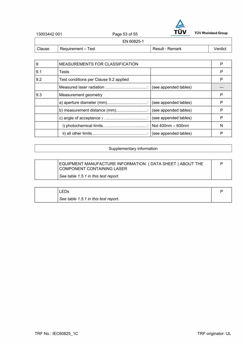
13003442 001 Page 53 of 55
EN 60825-1
Clause Requirement – Test Result - Remark Verdict
TRF No.: IEC60825_1C TRF originator: UL
9 MEASUREMENTS FOR CLASSIFICATION P
9.1 Tests P
9.2 Test conditions per Clause 9.2 applied P
Measured laser radiation ..................................... : (see appended tables) ―
9.3 Measurement geometry P
a) aperture diameter (mm)................................... : (see appended tables) P
b) measurement distance (mm)........................... : (see appended tables) P
c) angle of acceptance γ . .................................... : (see appended tables) P
i) photochemical limits…................................... : Not 400nm – 600nm N
ii) all other limits ................................................ : (see appended tables) P
Supplementary information
EQUIPMENT MANUFACTURE INFORMATION ( DATA SHEET ) ABOUT THE COMPONENT CONTAINING LASER
See table 1.5.1 in this test report.
P
LEDs
See table 1.5.1 in this test report.
P
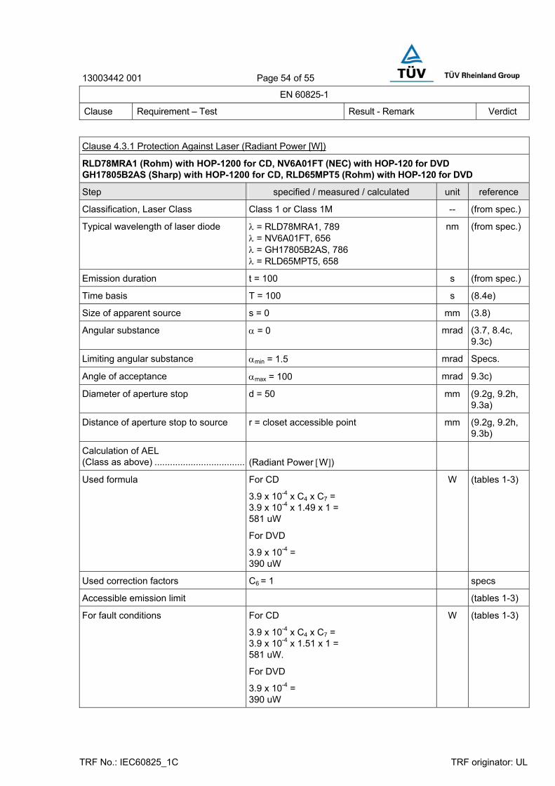
13003442 001 Page 54 of 55
EN 60825-1
Clause Requirement – Test Result - Remark Verdict
TRF No.: IEC60825_1C TRF originator: UL
Clause 4.3.1 Protection Against Laser (Radiant Power [W])
RLD78MRA1 (Rohm) with HOP-1200 for CD, NV6A01FT (NEC) with HOP-120 for DVD GH17805B2AS (Sharp) with HOP-1200 for CD, RLD65MPT5 (Rohm) with HOP-120 for DVD
Step specified / measured / calculated unit reference
Classification, Laser Class Class 1 or Class 1M -- (from spec.)
Typical wavelength of laser diode λ = RLD78MRA1, 789 λ = NV6A01FT, 656 λ = GH17805B2AS, 786 λ = RLD65MPT5, 658
nm (from spec.)
Emission duration t = 100 s (from spec.)
Time basis T = 100 s (8.4e)
Size of apparent source s = 0 mm (3.8)
Angular substance α = 0 mrad (3.7, 8.4c, 9.3c)
Limiting angular substance αmin = 1.5 mrad Specs.
Angle of acceptance αmax = 100 mrad 9.3c)
Diameter of aperture stop d = 50 mm (9.2g, 9.2h, 9.3a)
Distance of aperture stop to source r = closet accessible point mm (9.2g, 9.2h, 9.3b)
Calculation of AEL (Class as above) ....................................
(Radiant Power [W])
Used formula For CD
3.9 x 10⁻⁴ x C4 x C7 = 3.9 x 10-4 x 1.49 x 1 = 581 uW
For DVD
3.9 x 10-4 = 390 uW
W (tables 1-3)
Used correction factors C6 = 1 specs
Accessible emission limit (tables 1-3)
For fault conditions For CD
3.9 x 10⁻⁴ x C4 x C7 = 3.9 x 10-4 x 1.51 x 1 = 581 uW.
For DVD
3.9 x 10-4 = 390 uW
W (tables 1-3)

13003442 001 Page 55 of 55
EN 60825-1
Clause Requirement – Test Result - Remark Verdict
TRF No.: IEC60825_1C TRF originator: UL
Measurement results:
For normal condition: using Class 1 AEL
Class 1 : Measured radiant power:
RLD78MRA1= 46.0 uW NV6A01FT = 25.7 uW GH17805B2AS = 37.6 uW RLD65MPT5 = 31.7 uW
Class 1
For fault condition: using Class 1 AEL
Class 1 : Measured radiant power:
RLD78MRA1= 214 uW NV6A01FT = 380 uW GH17805B2AS = 245 uW RLD65MPT5 = 455 uW
Class 1 for CD
Class 1M for DVD