Embed Size (px)
Citation preview
PALOMAR COLLEGE ROOFING REPLACEMENT - BUILDING D
PROJECT NO: 5015008_// 04.05.2017
PALOMAR COLLEGE
1140 W MISSION ROAD, SAN MARCOS, CA 92069
100% Construction Documents
PALOMAR COLLEGE
ROOFING REPLACEMENT - BUILDING D
April 05, 2017
HMC # 5015008
_______________________________________________________ HMC ARCHITECTS
Architect
5015008 TABLE OF CONTENTS Roofing Replacement - Building D TOC - 1
TABLE OF CONTENTS DIVISION 00 - PROCUREMENT AND CONTRACTING REQUIREMENTS
PROVIDED BY OWNER
DIVISION 01 - GENERAL REQUIREMENTS
PROVIDED BY OWNER
DIVISION 02 - EXISTING CONDITIONS
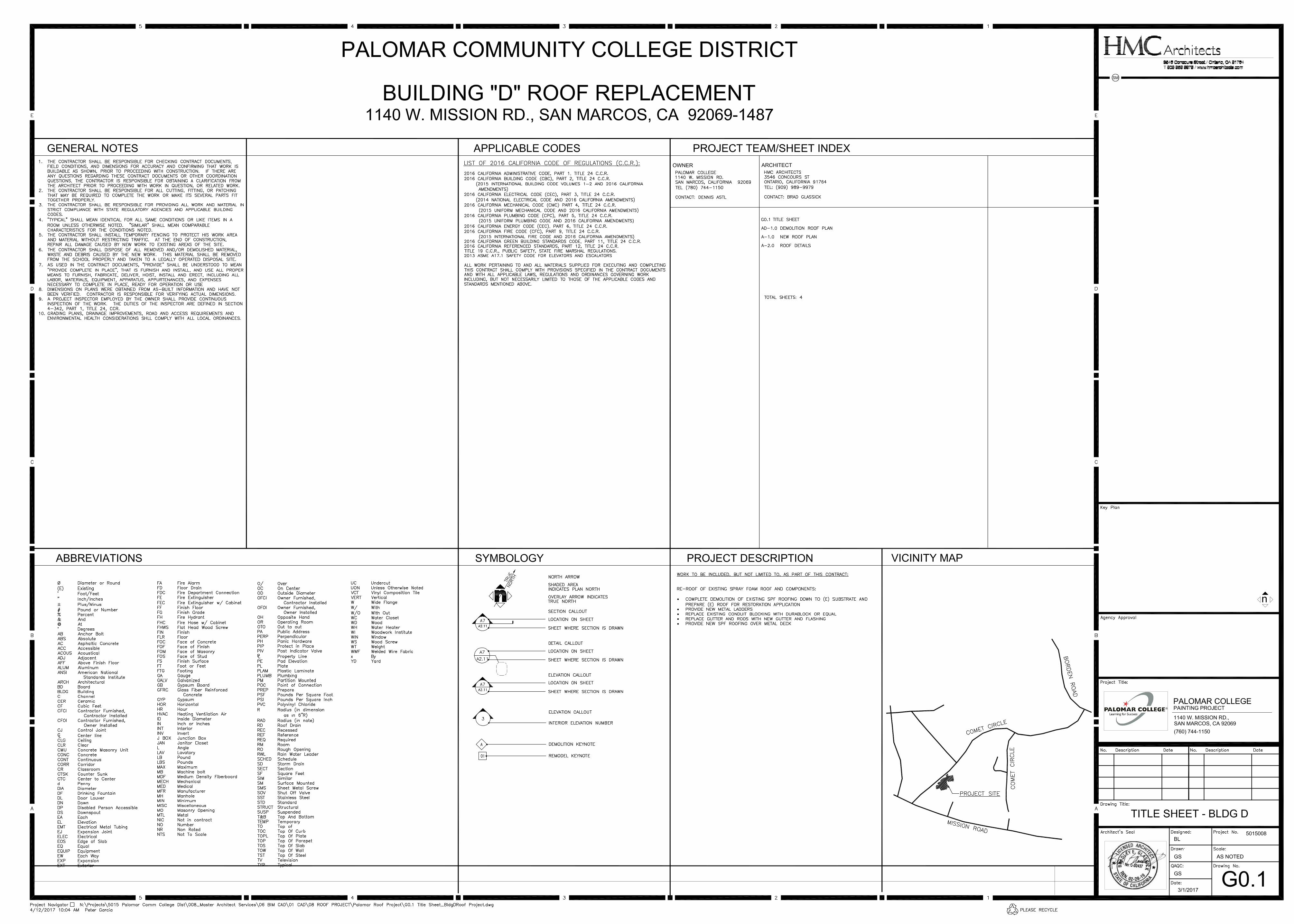
SECTION 02 41 19 - SELECTIVE DEMOLITION
DIVISION 05 - METALS
SECTION 05 51 33 - METAL LADDERS
DIVISION 06 - WOOD, PLASTICS, AND COMPOSITES
SECTION 06 10 00 - ROUGH CARPENTRY
DIVISION 07 - THERMAL AND MOISTURE PROTECTION
SECTION 07 01 50 - PREPARATION FOR RE-ROOFING SECTION 07 54 10 - ACRYLIC POLYURETHANE FOAM ROOF SYSTEM SECTION 07 54 12 - ACRYLIC POLYURETHANE FOAM ROOF SYSTEM OVER CORRUGATED
PANEL ROOF SECTION 07 62 00 - SHEET METAL FLASHING AND TRIM SECTION 07 92 00 - JOINT SEALANTS
DIVISION 09 - FINISHES
SECTION 09 90 00 - PAINTING
END OF TABLE OF CONTENTS
SECTION 02 41 19
SELECTIVE DEMOLITION
GENERALPART 1 -
SECTION INCLUDES1.01
Include Work required to demolish and remove elements of existing constructionA.including roofing and similar elements of existing building construction, all as noted onDrawings or as required to permit installation of new construction.
Comply with Title 24, Part 9, California Fire Code, Chapter 33 Fire Safety DuringB.Construction and Demolition, during all Phases of project.
REFERENCES1.02
CBC - 2016 California Building CodeA.CBC-19A - CBC Chapter 19A, Concrete1.CBC-33 - CBC Chapter 33, Safeguards During Construction2.
CCR - California Code of RegulationsB.CCR-8.4 - Title 8, Subchapter 4, Construction Safety Orders1.
CFC - 2016 California Fire CodeC.CFC-33 - CFC Chapter 33, Fire Safety During Construction and Demolition1.
NFPA - National Fire Protection AssociationD.NFPA 241- Safeguarding Construction, Alteration and Demolition Operations1.
SCAQMD - South Coast Air Quality Management DistrictE.SCAQMD-1403 - Rule 1403, Asbestos Emissions from Demolition/Renovation1.Activities
ADMINISTRATIVE REQUIREMENTS1.03
Pre-Demolition Conference: Conduct conference at Project site to comply with below .A.
Contractor shall schedule meeting after Notice of Award to review demolitionB.operations.
Attendance Required: Owner, Architect, Contractor, Demolition Subcontractors, ProjectC.Inspector.
Construction Process:D.Contractor shall discuss overview of demolition procedures.1.Contractor shall identify items to be selected by Owner for salvage.2.Contractor shall review special requirements for equipment, safety, and noise.3.
5015008 SELECTIVE DEMOLITIONRoofing Replacement - Building D 02 41 19 - 1
Architect will record minutes and distribute copies within seven days after meeting toE.participants and those affected by decisions made.
SUBMITTALS1.04
Pre-demolition Photographs or Video: Show existing conditions of adjoiningA.construction, including finish surfaces, that might be misconstrued as damage causedby demolition operations.
PRODUCTSPART 2 -
NOT USED.2.01
EXECUTIONPART 3 -
PREPARATION3.01
Protection:A.Protect existing items that are not indicated to be altered.1.Adequately protect staff and public from harm and accident during demolition2.operations by the erection of proper barricades, signs, or other safetyprecautions. Conform to Title 8, Subchapter 4, CCR and NFPA 241.
TEMPORARY MEASURES - LIFE SAFETY3.02
Emergency Exits: No enclosure, shield or protective covering shall interfere with useA.of emergency exits in existing facilities at any time. Rated egress systems shallprovide temporary rated egress.
Maintain fully charged certified compliant fire extinguishers and water hoses readilyB.available during demolition operations, per Section 906 CBC. Test electricalconductors for disconnection prior to removing.
Provide temporary, but equivalent, fire alarm, detection or suppression systems whenC.any system is impaired by Work of this Section. Temporary systems shall beinspected and tested monthly or at other more frequent intervals as required by Owner.
Impairment of fire protection systems, Section 3308.6: Impairments to any fire1.protection system shall be in accordance with Section 901.Systems out of Service: Per requirement of Section 901.7 through 901.7.6,2.California Fire Code.
Maintain free and unobstructed access to emergency services per Title 19, CFC 503.1;D.503.1.1, 503.4; and Appendix D, CFC Chapter 33 Sections 3310.1; 3312.1 and whenrequired by Owner.
Post NO SMOKING signs in English and Spanish, in number and location as approvedE.by Architect.
Reduce flammable and combustible fire load to minimum by daily removal of debris.F.
5015008 SELECTIVE DEMOLITIONRoofing Replacement - Building D 02 41 19 - 2
Instruct construction personnel in fire safety and fire drill policies appropriate for areasG.where demolition operations occur.
Deployment, disposition, administration and implementation of any and all safetyH.measures shall be sole responsibility of Contractor.
EXECUTION3.03
Demolish in orderly and careful manner. Maintain protected egress and access at allA.times.
Except where noted otherwise, immediately remove demolished materials from siteB.and dispose legally. Do not utilize Owner's disposal system.
Remove materials to be re-installed or retained in manner to prevent damage. StoreC.and protect until re-installation.
Do not burn or bury materials on site.D.
Upon completion of Work, leave areas of Work in clean condition.E.
SELECTIVE DEMOLITION, REPAIR AND ALTERATIONS WORK3.04
New and existing Work that is cut into, altered, damaged, relocated or reinstalled shallA.be restored to original conditions. Workmanship and materials to conform toapplicable provisions of other applicable Sections of Specifications.
Work shall be fully coordinated to ensure proper sequence, limits, methods and time ofB.performance. Arrange Work so as to impose a minimum of hardship on presentoperation of facilities.
Miscellaneous Removal Items: Items not specifically mentioned shall be removed asC.indicated on drawings.
Miscellaneous Work: Items not specifically mentioned shall be repaired, patched orD.finished like new Work or to match existing adjoining surfaces as approved. Surfacesdamaged shall be restored to original condition.
SALVAGE AND DISPOSAL3.05
Salvage: Offer Owner first right of refusal for the removed materials that may haveA.residual value. Remove items designated by the Owner to be salvaged with care.Clean, wrap or crate for storage and handling, and deliver to Owner as directed.
Disposal: Removed material, other than items directed to be salvaged or indicated toB.be reused, become Contractor's property upon removal, and shall be removed fromsite. Debris shall be picked up and disposed of, off site, by Contractor promptly andcontinuously as Work progresses, and not allowed to accumulate. Sprinkle the debristo prevent dust nuisance. Secure and pay for required hauling permits and paydumping fees and charges. Contractor shall make every reasonable effort to divertdebris to recycling or reuse facilities.
5015008 SELECTIVE DEMOLITIONRoofing Replacement - Building D 02 41 19 - 3
END OF SECTION
5015008 SELECTIVE DEMOLITIONRoofing Replacement - Building D 02 41 19 - 4
SECTION 05 51 33
METAL LADDERS
GENERALPART 1 -
SECTION INCLUDES1.01
Steel ladders galvanized and coated finish.A.Roof-to-roof ladders.1.
REFERENCES1.02
ANSI A14.3 - Ladders, Fixed, Safety Requirements.A.
CAL-OSHA - Construction Safety Orders, Chapter 8.B.
Chapter 10, 2016 California Building Code.C.
NOMMA – National Ornamental and Miscellaneous Metals AssociationD.Guidelines – Guideline 1: Joint Finishes1.
SUBMITTALS1.03
Shop Drawings: Indicate profiles, sizes, rivet connection attachments, reinforcing,A.anchorage, size and type of fasteners and accessories.
Product data describing assembly.B.
FIELD MEASUREMENTS1.04
Verify that field measurements are as indicated on shop drawings.A.
PRODUCTSPART 2 -
MANUFACTURER2.01
Products of the following manufacturers form the basis for design and quality intended.A.Cotterman Fixed Steel Ladders, Crosswell, MI. Product: Model; Series F modified1.for roof-to-roof ladder.Cundiff Steel Fabricating and Erection, Orange CA.2.
Or equal as approved in accordance with Division 01, General Requirements forB.substitutions.
MATERIALS2.02
Steel LaddersA.
5015008 METAL LADDERSRoofing Replacement - Building D 05 51 33 - 1
Steel Sections: ASTM A572, Grade 50. ASTM A992 for W-Shape sections and1.ASTM A36 for all other members.Rung: 3/4” round corrugated steel rungs, 12” on center.2.Steel Round Tubing: 1” diameter tubing for railings at pass thru, 24” apart.3.Plates, bars: ASTM A364.Pipe: ASTM A53, Grade B, Type E or S.5.Cage Ladders over 20 feet: 1/4 x 2 inch steel hoops at 4 feet oc, 7-3/16 x 1-1/26.inch vertical bars, welded construction, flared bottom, fabricated to conform withTitle 8, California Code of Regulations {OSHA}.Parapet Railing for Exterior ladders: 42 inches above top rung, extending 247.inches horizontally and return to roof. Space between railings: 24 inches.
Fasteners:B.General: Provide Type 304 or 316 stainless-steel fasteners for exterior use and1.zinc-plated fasteners with coating complying with ASTM B 633, Class Fe/Zn 5,where built into exterior walls. Select fasteners for type, grade, and classrequired.Bolts and Nuts: Regular hexagon-head bolts, ASTM A 307, Grade A; with hex nuts,2.ASTM A 563; and, where indicated, flat washers.Anchor Bolts: ASTM F 1554, Grade 36.3.Machine Screws: ASME B 18.6.3.4.Plain Washers: Round, carbon steel, ASME B18.22.1.5.Lock Washers: Helical, spring type, carbon steel, ASME B18.21.1.6.
FINISHES - STEEL LADDERS2.03
Galvanized items to minimum 2.0 ounces per square feet zinc coating accordance withA.ASTM A123, Grade 85.
Galvanized items to be painted: Do not use quenching solutions or treatmentsB.immediately after galvanizing. Refer to individual sections for galvanized items to bepainted, and to Section 09 90 00.
Prepare surfaces to be primed in accordance with SSPC.C.
Prime paint items with one coat.D.
Field Paint Finish: High Performance coating as specified in Section 09 90 00.E.
FABRICATION - GENERAL2.04
Fit and shop assemble in largest practical sections for delivery to site.A.
Fabricate components with joints tightly fitted and secured.B.
Supply components required for anchorage of fabrications. Fabricate anchors andC.related components of same material and finish as fabrication, except wherespecifically noted otherwise.
Accurately form components required for anchorage of members and to each otherD.and to building structure.
5015008 METAL LADDERSRoofing Replacement - Building D 05 51 33 - 2
Welded Joints. Seal joined members by continuous welds. Dress welded joints,E.leaving no burrs, or sharp or abrasive corners, edges or surfaces.
Where exposed to view, dress welds in accordance with NOMMA Guidelines for1.Finish 2.Where concealed, dress welds in accordance with NOMMA Guidelines for Finish2.3.
EXECUTIONPART 3 -
EXAMINATION3.01
Verify that field conditions are acceptable and are ready to receive work.A.
Beginning of installation means erector accepts existing conditions.B.
PREPARATION3.02
Supply items required to be cast into concrete or embedded in masonry with settingA.templates to appropriate section.
INSTALLATION3.03
Install items plumb and level, accurately fitted, free from distortion or defects.A.
Allow for erection loads, and for sufficient temporary bracing to maintain true alignmentB.until completion of erection and installation of permanent attachments.
Field bolt to match shop bolting.C.
Mechanically fasten joints butted tight, flush and hairline.D.
Obtain Architect’s approval prior to site cutting or making adjustments not scheduled.E.
Installation shall meet all requirements of ANSI A14.3, CAL-OSHA, and Chapter 10,F.California Building Code for lateral bracing.
ERECTION TOLERANCES3.04
Maximum Variation From Plumb: 1/4 inch per story, non-cumulative.A.
Maximum Offset From True Alignment: 1/4 inch.B.
END OF SECTION
5015008 METAL LADDERSRoofing Replacement - Building D 05 51 33 - 3
SECTION 06 10 00
ROUGH CARPENTRY
GENERALPART 1 -
SECTION INCLUDES1.01
Rough carpentry.A.
REFERENCES1.02
ASTM InternationalA.ASTM D 3498 - Adhesives for Field-Gluing Plywood to Lumber Framing for Floor1.SystemsASTM D 4601 - Asphalt-Coated Glass Fiber Base Sheet Used in Roofing.2.ASTM E 84 - Surface Burning Characteristics of Building Materials.3.
Chapters 7 and 23, 2016 California Building Code, CBC.B.
DOC PS 1-07 - Department of Commerce Product Standard, U. S. Product StandardC.for Construction and Industrial Plywood.
DOC PS 20-05 - Department of Commerce Product Standard, American SoftwoodD.Lumber Standards.
DOC PS 2-04 - Department of Commerce Product Standard, U. S. Product StandardE.for Construction, Performance Standard for Wood-Based Structural-Use Panels.
WWPA - Western Lumber Grading Rules 88, Latest Edition, by Western WoodF.Products Association.
APA - The Engineered Wood Association. The Construction Guide.G.
AQMD - Local Air Quality Management District Regulations.H.
Title 8 - California Code of Regulations, Construction Safety Orders.I.
ICC –ES – International Code Council Evaluation Service, Inc. Legacy Reports.J.
RIS – Redwood Inspection Service, Standard Specifications for Grades of CaliforniaK.Redwood Lumber, 1997.
SCAQMD – South Coast Air Quality Management District Rule 1168 - Adhesives andL.Sealants.
SUBMITTALS1.03
Product data and current ICC Legacy Reports for framing anchors.A.
5015008 ROUGH CARPENTRYRoofing Replacement - Building D 06 10 00 - 1
QUALITY ASSURANCE1.04
Rough Carpentry Lumber: Visible grade stamp on all products required.A.
Grade Stamp: Association under whose rules it was graded, or official grade mark ofB.other recognized grading agencies using grading rules, equivalent to WWPA orWCLIB.
Nailing guns and nail operators shall be approved in accordance with Title 8C.Construction Safety Orders.
DELIVERY, STORAGE AND HANDLING1.05
Do not deliver rough carpentry items until site conditions are adequate to receive theA.Work. Protect items from weather while in transit.
Store lumber and plywood at the site under cover or otherwise protected againstB.exposure to weather, raise above ground and out of contact with damp or wetsurfaces. Stack lumber and plywood and provide for air circulation within and aroundstacks and under temporary covers. For pressure treated lumber and plywood,provide spacers between courses to permit air circulation.
Install bracing as required. Make proper provision to take care of stresses resultingC.from construction loads, whenever piles materials, erection equipment or other loadsare carried by frame during its erection.
PROJECT CONDITIONS1.06
Cooperate with other trades in coordinating their Work with the Work of this Section.A.Provide wood grounds, blocking and nailer where indicated or as required for Work ofother trades.
PRODUCTSPART 2 -
ROUGH CARPENTRY MATERIALS2.01
Lumber: Graded in accordance with WWPA or WCLIB; maximum moisture content ofA.19 percent at time of installation. Provide Douglas Fir Larch for structural and framinglumber, surfaced four sides to standards of the grading association unless otherwiseindicated on Drawings, use the following grades:
Joists, lintels, horizontal framing, posts, studs and vertical framing: No. 1 unless1.otherwise indicated or noted on drawings.Non-bearing studs and plates, non-structural furring, concealed blocking,2.stripping and miscellaneous nailers and backing: No. 2 unless noted otherwise inthe structural drawings.
Plywood: Section 2303.1.4 CBC, Douglas Fir 1 Group Species, PS 1, APA Structural IB.Rated Sheathing. Bond Classification; Exterior plywood grade. Thickness asindicated, span rating sized for spacing.
Thickness: Minimum 5/8 inch or as indicated on Drawings.1.
5015008 ROUGH CARPENTRYRoofing Replacement - Building D 06 10 00 - 2
Roof Plywood Decking: requiring FM 1-90 Wind and Fire Classification, minimum 5/8””C.(19/32 inch) thick. Section 2304.7.2 CBC, Douglas Fir 1 Group Species, PS 1, APAStructural I Rated Sheathing. Bond Classification: Exposure 1, B-C Veneer Grade,sanded 1 side. Thickness as indicated, span rating sized for spacing.
Fasteners to attach wood decking to Metal decking: Dekfast #12 Phillips Head1.Screw or equal and as recommended by roof manufacturer. Non-corrosive, drillpoints, Factory Mutual approved for Class 1-90 uplift, with lengths sufficient topenetrate deck minimum of 3/4 inch with 3 inch metal stress plate.
Nails, Spikes and Staples: Section 2304.9 CBC, Galvanized for exterior applications,D.high humidity locations and treated wood; plain finish for other interior locations; sizeand type to suit application. Comply with Table 2304.9.1. Use common nails only.
Bolts, Nuts, Washers, Lags, Pins and Screws: Section 2304.9 CBC, sized to suitE.application, galvanized for exterior locations, high humidity locations and treated wood,plain finish for other interior locations. Full diameter body bolts only per ASMEB18.2.1(.2) or B18.2.6 for structural applications.
Stock Framing Connectors: Section 2304.9 CBC types indicated on Drawings,F.galvanized, with nails fully driven in all holes in each face of connector. Conform to thefollowing.
Manufacturers: Simpson Strong Tie Co., Inc., San Leandro, CA, United Steel1.Products, Montgomery, MN. or equal as approved in accordance with Division 01General Requirements for Substitutions.ICC Listed.2.
Non-Stock Framing Connectors: Conform to details.G.
EXECUTIONPART 3 -
LAYOUT MARKINGS3.01
Layout markings shall not be made with xylene-based inks, paint, or dyes, or with otherA.solvent-based products that may bleed through finishes.
FRAMING3.02
Erect wood framing and nailing members true to lines and levels. Do not deviate fromA.true alignment more than 1/4 inch in 10 feet, non-cumulative.
Construct members of continuous pieces of longest possible lengths.B.
Double wall framing members at openings over 100 square inches. Space shortC.members above and below openings in same manner as for walls.
Provide double joist headers at joist ends and around openings unless otherwiseD.indicated on Drawings. Bridge joists and rafters to conform Section 2304 CBC and asnoted on plans. For pre-manufactured joists, provide bridging in accordance withmanufacturer’s recommendations.
5015008 ROUGH CARPENTRYRoofing Replacement - Building D 06 10 00 - 3
Conform to Section 2308.9.8, CBC, where pipes penetrate sills or plates.E.
Cutting and Notching: Conform to Section 2308.9.10, CBC.F.
Bored Holes: Conform to Section 2308.9.11, CBC.G.
Conform to Section 717, California Building Code for fire blocks and draft stops. FireH.blocks and stops at 10-feet intervals and at ceiling level.
FINISH3.03
Final finish: paint per Section 09 90 00, Painting.A.
END OF SECTION
5015008 ROUGH CARPENTRYRoofing Replacement - Building D 06 10 00 - 4
SECTION 07 01 50
PREPARATION FOR RE-ROOFING
GENERALPART 1 -
SECTION INCLUDES1.01
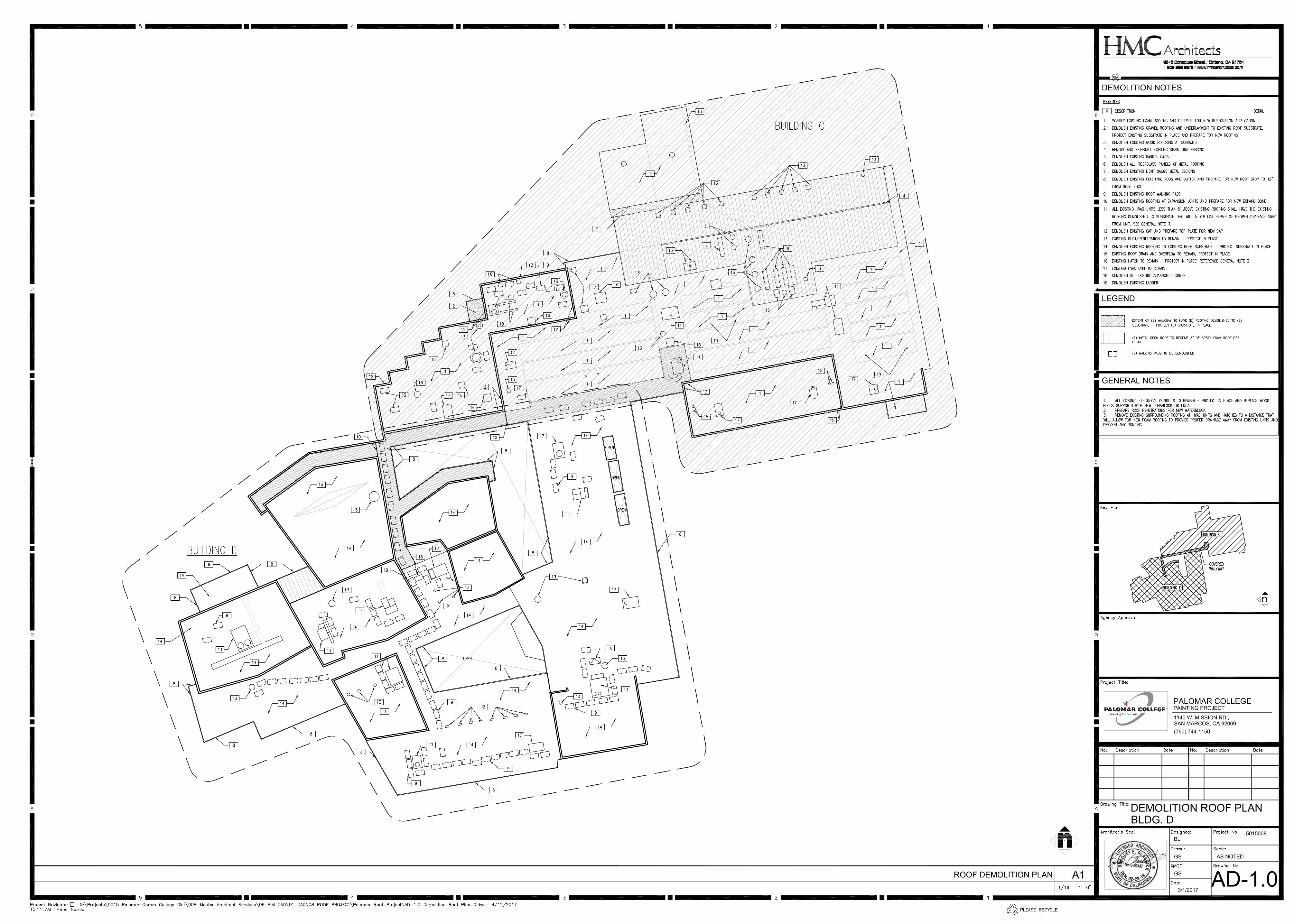
Removal of existing roofing covering in preparation for a new roof system.A.
Related Sections:B.Section 07 62 00, Sheet Metal Flashing and Trim.1.
SYSTEM DESCRIPTION1.02
Extent of Roof Area: Remove existing roof system, perimeter flashings and insulation.A.
PRE-INSTALLATION CONFERENCE1.03
Attendance Mandatory at conference required in section specifying new roofingA.installation.
Establish at pre-bid job walk, number of layers to be removed and reconfirm atB.pre-installation conference.
ENVIRONMENTAL REQUIREMENTS1.04
Do not remove existing roofing membrane when weather conditions threaten theA.integrity of the building contents or intended continued occupancy.
Maintain continuous temporary protection during and prior to installation of new roofingB.system.
SCHEDULING1.05
Schedule work to coincide with commencement of installation of new roofing system.A.
Remove only existing roofing materials that can be replaced with new materials as theB.weather will permit.
COORDINATION1.06
Coordinate work with other affected mechanical and electrical work associated withA.roof penetrations.
5015008 PREPARATION FOR RE-ROOFINGRoofing Replacement - Building D 07 01 50 - 1
PRODUCTSPART 2 -
MATERIALS2.01
Temporary Protection: Sheet polyethylene of thickness sufficient to prevent tearing orA.damage during use. Provide weights to retain sheeting in position.
EXECUTIONPART 3 -
EXAMINATION3.01
Verify existing site conditions.A.
Verify that existing roof surface is clear and ready for work of this Section.B.
PREPARATION3.02
Sweep roof surface clean of loose matter. Remove loose refuse and dispose off siteA.legally.
Free Fall Maximum: 8 ft. Provide enclosed chutes for higher fall.1.Provide disposals sufficiently sized to prevent debris from scattering around2.areas.Use support systems, intake hoppers, protective liners and durable3.non-breakable chutes. Max-Access Inc., Houston, TX, Chutes International,White Plains, MD or equal.Do not use Owner's disposal system.4.
MATERIALS REMOVAL3.03
Remove metal counter flashings.A.
Remove roofing system, perimeter base flashings, flashings around roof protrusionsB.and as indicated on drawings.
Repair existing wood deck surface to provide smooth working surface for new roofC.system.
Legally dispose of removed materials off-site.D.
TEMPORARY PROTECTION3.04
Provide temporary protective sheeting over uncovered deck surfaces.A.
Turn sheeting up and over parapets and curbing. Retain sheeting in position withB.weights.
Provide for surface drainage from sheeting to existing drainage facilities.C.
Do not permit traffic over unprotected or repaired deck surface.D.
5015008 PREPARATION FOR RE-ROOFINGRoofing Replacement - Building D 07 01 50 - 2
END OF SECTION
5015008 PREPARATION FOR RE-ROOFINGRoofing Replacement - Building D 07 01 50 - 3
5015008 ACRYLIC POLYURETHANE FOAM ROOF SYSTEM Roofing Replacement - Building D 07 54 10 - 1
SECTION 07 54 10
ACRYLIC POLYURETHANE FOAM ROOF SYSTEM
PART 1 - GENERAL
1.01 WORK INCLUDED
A. Removal of Existing Roof System & preparation of substrate
B. Sprayed-in-place Zero Ozone Depleting Polyurethane Foam Insulation
C. Energy Star Acrylic Coating & Granule Application
1.02 RELATED WORK
A. Section 01410: Testing Laboratory Services
B. Section 07 62 00: Sheet Metal Flashing and Trim
C. Section 07 72 00: Roof Accessories
1.03 QUALITY ASSURANCE
A. Contractor Qualifications: Must be a Manufacturer Approved Applicator and qualify for the manufacturer roof warranty specified for this project. Contractor shall carry 5,000,000 liability insurance. Contractor shall have been in business a minimum of ten years under the same name.
B. The roofing manufacturer approved roofing contractor shall perform the work of this section. Subcontracting the SPF roofing work is not allowed.
C. Manufacturer Qualifications: Both foam and coating manufacturer must be currently ISO 9001-2008 certified. Manufacturer may not have co-ownership, own or operate any part of the roofing contracting company. No private label products are acceptable.
D. Inspections: Completed roofing application will be inspected by the manufacturer’s field inspector to verify compliance with this specification and warranty requirements. Owner may elect to contract with its own consultant to take slit samples to verify compliance with the specification. Manufacturer’s representative shall conduct pre-start deck inspection and interim inspections as required.
5015008 ACRYLIC POLYURETHANE FOAM ROOF SYSTEM Roofing Replacement - Building D 07 54 10 - 2
1.04 SUBMITTALS
A. Product Data: Provide two copies of product data sheets for each product to be used to complete this roofing project.
B. Samples: Provide a sample of completed roof system showing surface texture and finished thickness of polyurethane foam, color and thickness of acrylic roof coating.
C. Submit roofing contractors current approved contractor certificate from the roofing manufacturer issuing the warranty for this project.
D. Provide specimen of manufacturer’s warranty to be issued for this roof installation.
E. Submit proof of Underwriters Laboratories UL 790 Class A or B fire classification over existing substrate.
F. Submit proof from an ASTM accredited testing laboratory on the testing laboratories letterhead that confirms the coating meets all the tests required for the coating to be ASTM D6083 compliant and meets the minimum physical property values specified herein.
G. Submit proof that the coating meets Title 24 requirements and is Energy Star listed.
H. Submit proof of Initial & Aged SRI Values for the coating as listed on the Cool Roof Rating Council website, www.coolroofs.org.
I. Submit proof from an independent ISO audit firm that the manufacturer of the foam and the coating is ISO 9001-2008 certified.
1.05 DELIVERY, STORAGE AND HANDLING
A. Deliver materials to the site in their original, tightly sealed containers, all clearly labeled with manufacturer’s name, product identification and lot number. Drums shall contain the UL label with Classification # as proof of subscribing to the UL Follow Up Testing Program.
B. Store materials in their original containers out of the weather and where the temperatures are within the limits specified by the manufacturer.
C. All materials shall be stored in compliance with applicable fire and safety requirements.
D. Protect materials from damage during transit, handling, storage and installation.
5015008 ACRYLIC POLYURETHANE FOAM ROOF SYSTEM Roofing Replacement - Building D 07 54 10 - 3
1.06 ENVIRONMENTAL CONDITIONS
A. No roofing materials shall be applied during periods of inclement weather (rain, snow, fog, mist or high humidity).
B. Do not apply the polyurethane foam when substrate or ambient air temperatures are below 50oF unless specifically approved in writing by the polyurethane foam manufacturer.
C. Do not apply the polyurethane foam when the substrate surface is less than 5oF above the dew point.
D. Do not apply acrylic roof coating when weather conditions will not permit complete cure before rain, dew, fog or freezing temperatures occur. Do not apply in late afternoon if heavy moisture condensation may appear during the night.
E. When wind speeds exceed 10 miles per hour at the job site, windscreens shall be used during the application of the surface primer, polyurethane foam and acrylic roof coating to prevent overspray onto surfaces not intended to receive foam and coating. Under no circumstances shall the surface primer, polyurethane foam or acrylic roof coating be applied when wind speeds exceed 15 miles per hour.
1.07 WARRANTY
A. Upon satisfactory completion of the work, provide: 1. Manufacturer’s Ten Year No Dollar Limit (NDL)System Warranty.
Warranty shall cover the cost of material and labor required to repair leaks in the roof system specified herein caused by defective materials or installation of materials.
PART 2 - PRODUCTS
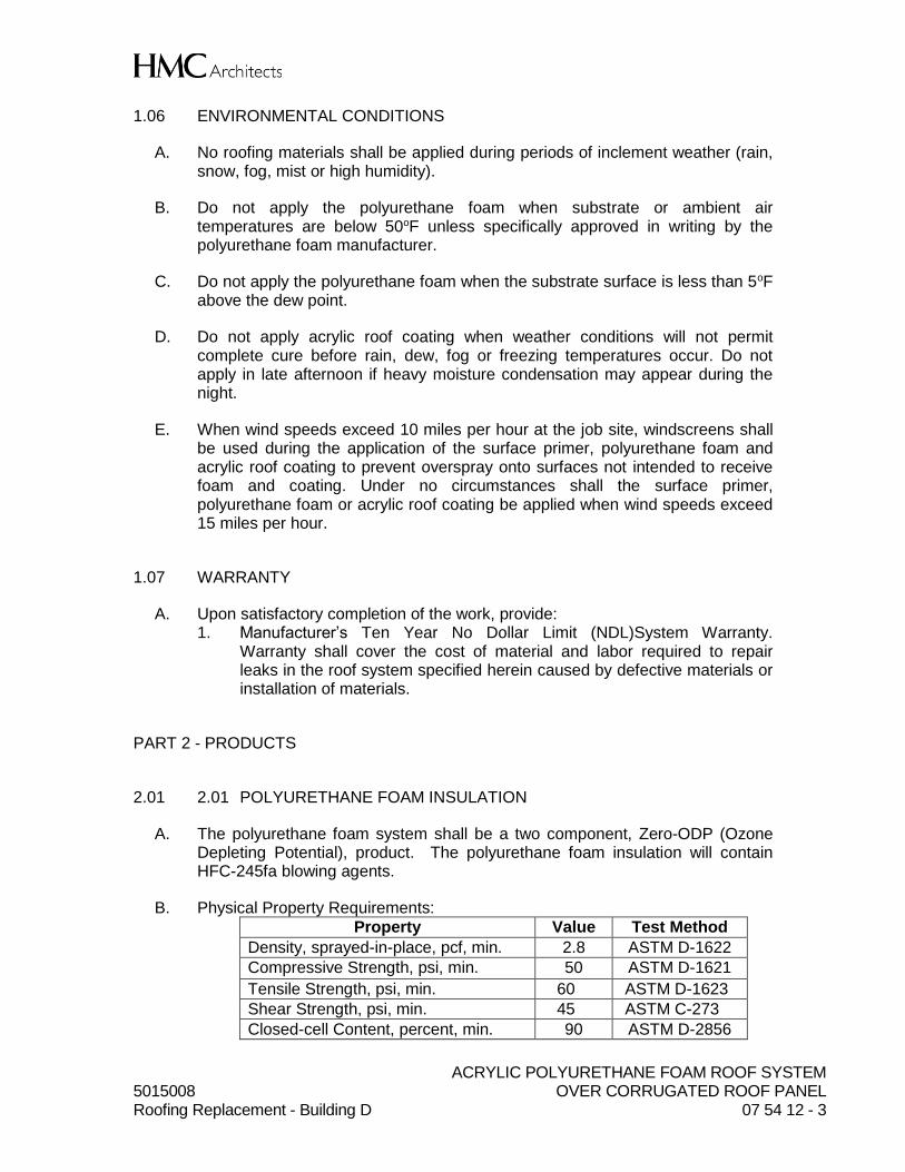
2.01 POLYURETHANE FOAM INSULATION
A. The polyurethane foam system shall be a two component, Zero-ODP (Ozone Depleting Potential), product. The polyurethane foam insulation will contain HFC-245fa blowing agents.
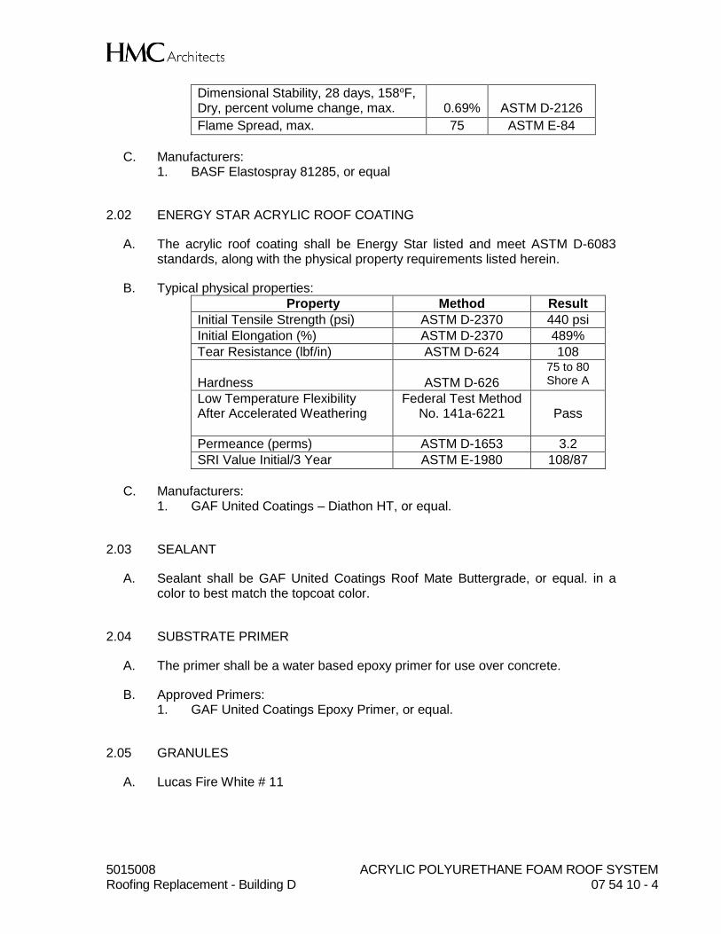
B. Physical Property Requirements:
Property Value Test Method
Density, sprayed-in-place, pcf, min. 2.8 ASTM D-1622
Compressive Strength, psi, min. 50 ASTM D-1621
Tensile Strength, psi, min. 60 ASTM D-1623
Shear Strength, psi, min. 45 ASTM C-273
Closed-cell Content, percent, min. 90 ASTM D-2856
K-Factor = R Value 6.3 per inch .158 ASTM -518
5015008 ACRYLIC POLYURETHANE FOAM ROOF SYSTEM Roofing Replacement - Building D 07 54 10 - 4
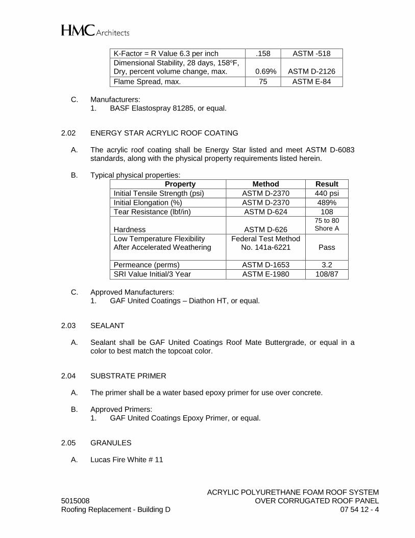
Dimensional Stability, 28 days, 158oF, Dry, percent volume change, max.
0.69%
ASTM D-2126
Flame Spread, max. 75 ASTM E-84
C. Manufacturers: 1. BASF Elastospray 81285, or equal
2.02 ENERGY STAR ACRYLIC ROOF COATING
A. The acrylic roof coating shall be Energy Star listed and meet ASTM D-6083 standards, along with the physical property requirements listed herein.
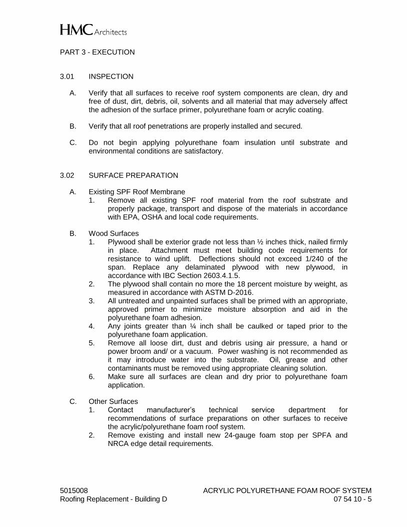
B. Typical physical properties:
Property Method Result
Initial Tensile Strength (psi) ASTM D-2370 440 psi
Initial Elongation (%) ASTM D-2370 489%
Tear Resistance (lbf/in) ASTM D-624 108
Hardness
ASTM D-626
75 to 80 Shore A
Low Temperature Flexibility After Accelerated Weathering
Federal Test Method No. 141a-6221
Pass
Permeance (perms) ASTM D-1653 3.2
SRI Value Initial/3 Year ASTM E-1980 108/87
C. Manufacturers: 1. GAF United Coatings – Diathon HT, or equal.
2.03 SEALANT
A. Sealant shall be GAF United Coatings Roof Mate Buttergrade, or equal. in a color to best match the topcoat color.
2.04 SUBSTRATE PRIMER
A. The primer shall be a water based epoxy primer for use over concrete.
B. Approved Primers: 1. GAF United Coatings Epoxy Primer, or equal.
2.05 GRANULES
A. Lucas Fire White # 11
5015008 ACRYLIC POLYURETHANE FOAM ROOF SYSTEM Roofing Replacement - Building D 07 54 10 - 5
PART 3 - EXECUTION
3.01 INSPECTION
A. Verify that all surfaces to receive roof system components are clean, dry and free of dust, dirt, debris, oil, solvents and all material that may adversely affect the adhesion of the surface primer, polyurethane foam or acrylic coating.
B. Verify that all roof penetrations are properly installed and secured.
C. Do not begin applying polyurethane foam insulation until substrate and environmental conditions are satisfactory.
3.02 SURFACE PREPARATION
A. Existing SPF Roof Membrane 1. Remove all existing SPF roof material from the roof substrate and
properly package, transport and dispose of the materials in accordance with EPA, OSHA and local code requirements.
B. Wood Surfaces 1. Plywood shall be exterior grade not less than ½ inches thick, nailed firmly
in place. Attachment must meet building code requirements for resistance to wind uplift. Deflections should not exceed 1/240 of the span. Replace any delaminated plywood with new plywood, in accordance with IBC Section 2603.4.1.5.
2. The plywood shall contain no more the 18 percent moisture by weight, as measured in accordance with ASTM D-2016.
3. All untreated and unpainted surfaces shall be primed with an appropriate, approved primer to minimize moisture absorption and aid in the polyurethane foam adhesion.
4. Any joints greater than ¼ inch shall be caulked or taped prior to the polyurethane foam application.
5. Remove all loose dirt, dust and debris using air pressure, a hand or power broom and/ or a vacuum. Power washing is not recommended as it may introduce water into the substrate. Oil, grease and other contaminants must be removed using appropriate cleaning solution.
6. Make sure all surfaces are clean and dry prior to polyurethane foam application.
C. Other Surfaces 1. Contact manufacturer’s technical service department for
recommendations of surface preparations on other surfaces to receive the acrylic/polyurethane foam roof system.
2. Remove existing and install new 24-gauge foam stop per SPFA and NRCA edge detail requirements.
5015008 ACRYLIC POLYURETHANE FOAM ROOF SYSTEM Roofing Replacement - Building D 07 54 10 - 6
3.03 SURFACE PRIMER
A. Inspection 1. Prior to application of the primer, inspect the substrates to be primed to
ensure preparations required in Section 3.02 have been met. 2. Surface primer shall not be applied unless the environmental conditions
of Section 1.06 are met.
B. Application 1. Apply the surface primer in strict accordance with the manufacturer’s
application instructions. 2. Confirm primer is cured before installing polyurethane foam insulation.
3.04 POLYURETHANE FOAM APPLICATION
A. Inspection 1. Prior to polyurethane foam application, inspect the substrate surface to
ensure preparations required in Section 3.02 have been met. 2. Polyurethane foam shall not be applied unless the environmental
requirements of Section 1.06 are met.
B. Application 1. Apply the polyurethane foam in accordance with the polyurethane foam
manufacturer’s specifications and application instructions, using spray equipment recommended by the foam manufacturer.
2. Polyurethane foam shall be applied in the field of the pass in a minimum of 1/2-inch-thick and maximum 1.5 inch. The total thickness of the polyurethane foam shall be a minimum of 1.5 inches on the roof deck, except where tapering is required to facilitate drainage or a self-flashing termination.
3. Apply the full thickness of polyurethane foam in any area on the same day. Phasing of the polyurethane foam is not acceptable.
4. Polyurethane foam shall be applied to ensure proper drainage resulting in no excessive ponding water.
5. The polyurethane foam shall be terminated neatly a minimum of four inches above the finished roof surface at roof penetrations. Foamed-in-place cants shall be applied to allow a smooth transition from the horizontal to vertical surface. Crickets shall be constructed of plywood or polyurethane foam.
6. The finished polyurethane foam surface texture shall be smooth to orange-peel, free of voids, pinholes and depressions. Verge of popcorn texture is acceptable if it can be thoroughly and completely coated. Popcorn and tree bark textures are not acceptable. Unacceptable foam textures shall be removed, primed and re-foamed as recommended in writing by the SPF manufacturer prior to coating application.
3.05 ACRYLIC ROOF COATING APPLICATION
A. Inspection
5015008 ACRYLIC POLYURETHANE FOAM ROOF SYSTEM Roofing Replacement - Building D 07 54 10 - 7
1. Prior to the application of the acrylic roof coating inspect the polyurethane foam surface to ensure the conditions of Section 3.03 have been met.
2. The polyurethane foam surface shall be free of dust, dirt, debris and other contaminants that would impair the adhesion of the acrylic coating.
3. The polyurethane foam surface must be dry prior to the acrylic coating application.
4. If more than 24 hours’ elapse between the polyurethane foam application and the start of the acrylic coating application, the coating manufacturer shall thoroughly inspect the polyurethane foam surface for UV degradation and oxidation. If this condition is detected, the polyurethane foam surface shall be prepared and treated as recommended by the coating manufacturer before coating is installed.
5. Make sure all environmental conditions of Section 1.06 are met prior to acrylic coating application.
B. Application 1. The acrylic roof coating first coat shall be applied on the same day as the
polyurethane foam application, after the polyurethane foam has been allowed to cure a minimum of two hours and in no case more than 24 hours after the installation of the polyurethane insulation.
2. Apply acrylic roof coating basecoat in a uniform application to achieve a finished dry mil thickness of approximately ⅓ the total millage required for the roof or 1½ gallons per 100 square feet or as is required for a dry mil thickness of 12 mils. Additional coating may be required to achieve 12 dry mils, depending upon the surface texture of the foam insulation.
3. The first coat shall not be subjected to foot traffic or be disturbed until it is cured.
4. After the first coat has cured, inspect the coating for pinholes, cracks, thin areas or other deviations. All deviations observed shall be caulked with buttergrade sealant and/or roller coated with additional acrylic roof coating prior to applying subsequent coats.
5. The first coat must be cured, clean and free of all moisture prior to application of subsequent coats.
6. Apply the topcoat in a uniform manner to the first coat within 72 hours of the first coat application. Install the topcoat at 1½ gallons per 100 square feet or as is required for a total protective coating system dry film thickness of 25 dry mils. Topcoat shall be a contrasting color to the first coat. Topcoat shall be white and Energy Star approved.
7. The acrylic roof coating shall be applied a minimum of two inches beyond all the terminated edges of the polyurethane foam. These terminations should be masked to provide a neat finished appearance. The high tensile acrylic coating shall be installed to all parapet walls at 25 dry mils in a minimum of two coats.
8. Allow the topcoat to cure and inspect the finished coating surface for pinholes, cracks, thin areas or other deviations. Repair any deviations observed with buttergrade sealant and/or additional acrylic roof coating topcoat.
9. It is the contractor’s responsibility to ensure the minimum total dry film thickness specified is achieved throughout the entire roof area.
10. Granule Application: Granules shall be installed six feet wide around equipment areas as marked on the drawings. Install Lucas Bright White
5015008 ACRYLIC POLYURETHANE FOAM ROOF SYSTEM Roofing Replacement - Building D 07 54 10 - 8
granules into the wet topcoat at the rate of 30 lbs per 100 square feet. Once the coating has cured, remove excessive granules from the roof. Install two additional coats of coating at the rate of 1½ gallons per 100 square feet per coat over the granules.
3.06 FIELD QUALITY CONTROL – MANUFACTURER WARRANTED ROOFS
A. Slit samples of the high tensile acrylic coating will be taken by the coating manufacturer’s field inspector at a rate of 3 per 10,000 square feet, with a minimum of 3 per roof, to test the coating thickness and quality. Sampled areas will be repaired using manufacturer’s butter grade sealant and polyester fabric.
3.07 SAFETY REQUIREMENTS
A. Proper safety precautions shall be followed throughout the entire roofing operation OSHA and local regulations shall be strictly followed. Refer to the roofing product’s Safety Data Sheets for specific safety information on handling and working with all materials. Dispose of all trash, debris and empty containers in accordance with local, state and federal regulations.
END OF SECTION
ACRYLIC POLYURETHANE FOAM ROOF SYSTEM 5015008 OVER CORRUGATED ROOF PANEL Roofing Replacement - Building D 07 54 12 - 1
SECTION 07 54 12
ACRYLIC POLYURETHANE FOAM ROOF SYSTEM OVER CORRUGATED PANEL ROOF
PART 1 - GENERAL
1.01 WORK INCLUDED
A. Preparation of Existing Corrugated Panel Roof
B. Sprayed-in-place Zero Ozone Depleting Polyurethane Foam Insulation
C. Energy Star High Tensile Acrylic Coating Application
1.02 RELATED WORK
A. Section 01410: Testing Laboratory Services
B. Section 07 62 00: Sheet Metal Flashing and Trim
C. Section 07 72 00: Roof Accessories
1.03 QUALITY ASSURANCE
A. Contractor Qualifications: Must be a Manufacturer Approved Applicator and qualify for the manufacturer roof warranty specified for this project. Contractor shall carry 5,000,000 liability insurance. Contractor shall have been in business a minimum of ten years under the same name.
B. The roofing manufacturer approved roofing contractor shall perform the work of this section. Subcontracting the SPF roofing work is not allowed.
C. Manufacturer Qualifications: Both foam and coating manufacturer must be currently ISO 9001-2008 certified. Manufacturer may not have co-ownership, own or operate any part of the roofing contracting company. No private label products are acceptable.
D. Inspections: Completed roofing application will be inspected by the manufacturer’s field inspector to verify compliance with this specification and warranty requirements. Owner may elect to contract with its own consultant to take slit samples to verify compliance with the specification. Manufacturer’s representative shall conduct pre-start deck inspection and interim inspections as required.
ACRYLIC POLYURETHANE FOAM ROOF SYSTEM 5015008 OVER CORRUGATED ROOF PANEL Roofing Replacement - Building D 07 54 12 - 2
1.04 SUBMITTALS
A. Product Data: Provide two copies of product data sheets for each product to be used to complete this roofing project.
B. Samples: Provide a sample of completed roof system showing surface texture and finished thickness of polyurethane foam, color and thickness of acrylic roof coating.
C. Submit roofing contractors current approved contractor certificate from the roofing manufacturer issuing the warranty for this project.
D. Provide specimen of manufacturer’s warranty to be issued for this roof installation.
E. Submit proof of Underwriters Laboratories UL 790 Class A or B fire classification over existing substrate.
F. Submit proof from an ASTM accredited testing laboratory on the testing laboratories letterhead that confirms the coating meets all the tests required for the coating to be ASTM D6083 compliant and meets the minimum physical property values specified herein.
G. Submit proof that the coating meets Title 24 requirements and is Energy Star listed.
H. Submit proof of Initial & Aged SRI Values for the coating as listed on the Cool Roof Rating Council website, www.coolroofs.org.
I. Submit proof from an independent ISO audit firm that the manufacturer of the foam and the coating is ISO 9001-2008 certified.
1.05 DELIVERY, STORAGE AND HANDLING
A. Deliver materials to the site in their original, tightly sealed containers, all clearly labeled with manufacturer’s name, product identification and lot number. Drums shall contain the UL label with Classification # as proof of subscribing to the UL Follow Up Testing Program.
B. Store materials in their original containers out of the weather and where the temperatures are within the limits specified by the manufacturer.
C. All materials shall be stored in compliance with applicable fire and safety requirements.
D. Protect materials from damage during transit, handling, storage and installation.
ACRYLIC POLYURETHANE FOAM ROOF SYSTEM 5015008 OVER CORRUGATED ROOF PANEL Roofing Replacement - Building D 07 54 12 - 3
1.06 ENVIRONMENTAL CONDITIONS
A. No roofing materials shall be applied during periods of inclement weather (rain, snow, fog, mist or high humidity).
B. Do not apply the polyurethane foam when substrate or ambient air temperatures are below 50oF unless specifically approved in writing by the polyurethane foam manufacturer.
C. Do not apply the polyurethane foam when the substrate surface is less than 5oF above the dew point.
D. Do not apply acrylic roof coating when weather conditions will not permit complete cure before rain, dew, fog or freezing temperatures occur. Do not apply in late afternoon if heavy moisture condensation may appear during the night.
E. When wind speeds exceed 10 miles per hour at the job site, windscreens shall be used during the application of the surface primer, polyurethane foam and acrylic roof coating to prevent overspray onto surfaces not intended to receive foam and coating. Under no circumstances shall the surface primer, polyurethane foam or acrylic roof coating be applied when wind speeds exceed 15 miles per hour.
1.07 WARRANTY
A. Upon satisfactory completion of the work, provide: 1. Manufacturer’s Ten Year No Dollar Limit (NDL)System Warranty.
Warranty shall cover the cost of material and labor required to repair leaks in the roof system specified herein caused by defective materials or installation of materials.
PART 2 - PRODUCTS
2.01 2.01 POLYURETHANE FOAM INSULATION
A. The polyurethane foam system shall be a two component, Zero-ODP (Ozone Depleting Potential), product. The polyurethane foam insulation will contain HFC-245fa blowing agents.
B. Physical Property Requirements:
Property Value Test Method
Density, sprayed-in-place, pcf, min. 2.8 ASTM D-1622
Compressive Strength, psi, min. 50 ASTM D-1621
Tensile Strength, psi, min. 60 ASTM D-1623
Shear Strength, psi, min. 45 ASTM C-273
Closed-cell Content, percent, min. 90 ASTM D-2856
ACRYLIC POLYURETHANE FOAM ROOF SYSTEM 5015008 OVER CORRUGATED ROOF PANEL Roofing Replacement - Building D 07 54 12 - 4
K-Factor = R Value 6.3 per inch .158 ASTM -518
Dimensional Stability, 28 days, 158oF, Dry, percent volume change, max.
0.69%
ASTM D-2126
Flame Spread, max. 75 ASTM E-84
C. Manufacturers: 1. BASF Elastospray 81285, or equal.
2.02 ENERGY STAR ACRYLIC ROOF COATING
A. The acrylic roof coating shall be Energy Star listed and meet ASTM D-6083 standards, along with the physical property requirements listed herein.
B. Typical physical properties:
Property Method Result
Initial Tensile Strength (psi) ASTM D-2370 440 psi
Initial Elongation (%) ASTM D-2370 489%
Tear Resistance (lbf/in) ASTM D-624 108
Hardness
ASTM D-626
75 to 80 Shore A
Low Temperature Flexibility After Accelerated Weathering
Federal Test Method No. 141a-6221
Pass
Permeance (perms) ASTM D-1653 3.2
SRI Value Initial/3 Year ASTM E-1980 108/87
C. Approved Manufacturers: 1. GAF United Coatings – Diathon HT, or equal.
2.03 SEALANT
A. Sealant shall be GAF United Coatings Roof Mate Buttergrade, or equal in a color to best match the topcoat color.
2.04 SUBSTRATE PRIMER
A. The primer shall be a water based epoxy primer for use over concrete.
B. Approved Primers: 1. GAF United Coatings Epoxy Primer, or equal.
2.05 GRANULES
A. Lucas Fire White # 11
ACRYLIC POLYURETHANE FOAM ROOF SYSTEM 5015008 OVER CORRUGATED ROOF PANEL Roofing Replacement - Building D 07 54 12 - 5
2.06 EDGE METAL
A. 24 Gauge minimum with a 1” rise over wood nailer (refer to SPFA Detail)
PART 3 - EXECUTION
3.01 INSPECTION
A. Verify that all surfaces to receive roof system components are clean, dry and free of dust, dirt, debris, oil, solvents and all material that may adversely affect the adhesion of the surface primer, polyurethane foam or acrylic coating.
B. Verify that all roof penetrations are properly installed and secured.
C. Do not begin applying polyurethane foam insulation until substrate and environmental conditions are satisfactory.
3.02 SURFACE PREPARATION
A. Existing Corrugated Panel Roof 1. Ensure screw heads are in place and securely fastened. If screw heads
are missing, replace with next larger size screw head. 2. Verify that corrugated panel laps are secure. 3. Install new foam stop edge metal with a minimum 1” rise and a minimum
4” face over a new wood nailer, as indicated on the drawings. Install in accordance with SPFA, NRCA and roofing manufacturer guidelines.
4. Clean existing corrugated panels in accordance with manufacturer’s instructions.
B. Other Surfaces 1. Contact manufacturer’s technical service department for
recommendations of surface preparations on other surfaces to receive the acrylic/polyurethane foam roof system.
3.03 SURFACE PRIMER
A. Inspection 1. Prior to application of the primer, inspect the substrates to be primed to
ensure preparations required in Section 3.02 have been met. 2. Surface primer shall not be applied unless the environmental conditions
of Section 1.06 are met.
B. Application 1. Apply the surface primer in strict accordance with the manufacturer’s
application instructions at the rate of 1 gallon per 200 square feet. 2. Confirm primer is cured before installing polyurethane foam insulation.
ACRYLIC POLYURETHANE FOAM ROOF SYSTEM 5015008 OVER CORRUGATED ROOF PANEL Roofing Replacement - Building D 07 54 12 - 6
3. New edge metal shall be solvent wiped to remove shop oils and contaminants before priming.
3.04 POLYURETHANE FOAM APPLICATION
A. Inspection 1. Prior to polyurethane foam application, inspect the substrate surface to
ensure preparations required in Section 3.02 have been met. 2. Polyurethane foam shall not be applied unless the environmental
requirements of Section 1.06 are met.
B. Application 1. Apply the polyurethane foam in accordance with the polyurethane foam
manufacturer’s specifications and application instructions, using spray equipment recommended by the foam manufacturer.
2. Polyurethane foam shall be applied in the field of the pass in a minimum of 1/2-inch-thick and maximum 1.5 inch. The total thickness of the polyurethane foam shall be a minimum of 2.5 inches over the corrugated panel roof deck, except where tapering is required to facilitate drainage or a self-flashing termination.
3. Apply the full thickness of polyurethane foam in any area on the same day. Phasing of the polyurethane foam is not acceptable.
4. Polyurethane foam shall be applied to ensure proper drainage resulting in no excessive ponding water.
5. The polyurethane foam shall be terminated neatly a minimum of four inches above the finished roof surface at roof penetrations. Foamed-in-place cants shall be applied to allow a smooth transition from the horizontal to vertical surface. Crickets shall be constructed of plywood or polyurethane foam.
6. The finished polyurethane foam surface texture shall be smooth to orange-peel, free of voids, pinholes and depressions. Verge of popcorn texture is acceptable if it can be thoroughly and completely coated. Popcorn and tree bark textures are not acceptable. Unacceptable foam textures shall be removed, primed and re-foamed as recommended in writing by the SPF manufacturer prior to coating application.
7. Polyurethane foam terminated at new edge metal foam stop shall be V grooved and caulked with manufacturer approved urethane sealant per SPFA foam stop detail.
3.05 ACRYLIC ROOF COATING APPLICATION
A. Inspection 1. Prior to the application of the acrylic roof coating inspect the polyurethane
foam surface to ensure the conditions of Section 3.03 have been met. 2. The polyurethane foam surface shall be free of dust, dirt, debris and other
contaminants that would impair the adhesion of the acrylic coating. 3. The polyurethane foam surface must be dry prior to the acrylic coating
application.
ACRYLIC POLYURETHANE FOAM ROOF SYSTEM 5015008 OVER CORRUGATED ROOF PANEL Roofing Replacement - Building D 07 54 12 - 7
4. If more than 24 hours’ elapse between the polyurethane foam application and the start of the acrylic coating application, the coating manufacturer shall thoroughly inspect the polyurethane foam surface for UV degradation and oxidation. If this condition is detected, the polyurethane foam surface shall be prepared and treated as recommended by the coating manufacturer before coating is installed.
5. Make sure all environmental conditions of Section 1.06 are met prior to acrylic coating application.
B. Application 1. The acrylic roof coating first coat shall be applied on the same day as the
polyurethane foam application, after the polyurethane foam has been allowed to cure a minimum of two hours and in no case more than 24 hours after the installation of the polyurethane insulation.
2. Apply acrylic roof coating basecoat in a uniform application to achieve a finished dry mil thickness of approximately ⅓ the total millage required for the roof or 1½ gallons per 100 square feet or as is required for a dry mil thickness of 12 mils. Additional coating may be required to achieve 12 dry mils, depending upon the surface texture of the foam insulation.
3. The first coat shall not be subjected to foot traffic or be disturbed until it is cured.
4. After the first coat has cured, inspect the coating for pinholes, cracks, thin areas or other deviations. All deviations observed shall be caulked with buttergrade sealant and/or roller coated with additional acrylic roof coating prior to applying subsequent coats.
5. The first coat must be cured, clean and free of all moisture prior to application of subsequent coats.
6. Apply the topcoat in a uniform manner to the first coat within 72 hours of the first coat application. Install the topcoat at 1½ gallons per 100 square feet or as is required for a total protective coating system dry film thickness of 25 dry mils. Topcoat shall be a contrasting color to the first coat. Topcoat shall be white and Energy Star approved.
7. The acrylic roof coating shall be applied a minimum of two inches beyond all the terminated edges of the polyurethane foam. These terminations should be masked to provide a neat finished appearance. The high tensile acrylic coating shall be installed to all parapet walls at 25 dry mils in a minimum of two coats.
8. Allow the topcoat to cure and inspect the finished coating surface for pinholes, cracks, thin areas or other deviations. Repair any deviations observed with buttergrade sealant and/or additional acrylic roof coating topcoat. Edge metal areas V grooved and caulked shall receive additional two coats of high tensile acrylic coating a minimum 6 inches back on to roof surface for a total coating thickness of 45 dry mils.
9. It is the contractor’s responsibility to ensure the minimum total dry film thickness specified is achieved throughout the entire roof area.
10. Granule Application: Granules shall be installed six feet wide around equipment areas as marked on the drawings. Install Lucas Bright White granules into the wet topcoat at the rate of 30 lbs per 100 square feet. Once the coating has cured, remove excessive granules from the roof.
ACRYLIC POLYURETHANE FOAM ROOF SYSTEM 5015008 OVER CORRUGATED ROOF PANEL Roofing Replacement - Building D 07 54 12 - 8
Install two additional coats of coating at the rate of 1½ gallons per 100 square feet per coat over the granules.
3.06 FIELD QUALITY CONTROL – MANUFACTURER WARRANTED ROOFS
A. Slit samples of the high tensile acrylic coating will be taken by the coating manufacturer’s field inspector at a rate of 3 per 10,000 square feet, with a minimum of 3 per roof, to test the coating thickness and quality. Sampled areas will be repaired using manufacturer’s butter grade sealant and polyester fabric.
3.07 SAFETY REQUIREMENTS
A. Proper safety precautions shall be followed throughout the entire roofing operation OSHA and local regulations shall be strictly followed. Refer to the roofing product’s Safety Data Sheets for specific safety information on handling and working with all materials. Dispose of all trash, debris and empty containers in accordance with local, state and federal regulations.
END OF SECTION
SECTION 07 62 00
SHEET METAL FLASHING AND TRIM
GENERALPART 1 -
SUMMARY1.01
Section Includes:A.Roof flashings.1.Plumbing Vents.2.Flashings for electrical conduits, mechanical lines and plumbing water lines roof3.penetrations.Equipment Roof Curbs and Flashing.4.Equipment support stand penetrations.5.
Related Section:B.Section 09 90 00, Painting.1.
REFERENCES1.02
California Building Code 2016, Chapters 14 and 15.A.
American Society for Testing and Materials (ASTM)B.ASTM A653/A653M-98 - Sheet Steel, Zinc-Coated (Galvanized) or Zinc - Iron1.Alloy Coated by the Hot-Dip ProcessASTM B32 - Solder Metal2.ASTM D4601 - Asphalt-Coated Glass Fiber Base Sheet Used in Roofing3.
National Roofing Contractors Association (NRCA)C.NRCA Manual - Fifth Edition.1.
Sheet Metal and Air Conditioning Contractors National Association, Inc. (SMACNA)D.SMACNA Manual - Architectural Sheet Metal Manual, Current Edition1.
SUBMITTALS1.03
Shop drawings showing material profile, jointing pattern, jointing details, fasteningA.methods and installation details.
Product data.B.
Manufacturer's installation instructions.C.
Samples for each type of sheet metal flashing and trim indicated with field-appliedD.color finishes.
5015008 SHEET METAL FLASHING AND TRIMRoofing Replacement - Building D 07 62 00 - 1
STORAGE AND HANDLING1.04
Stack preformed and pre-finished material to prevent twisting, bending, or abrasionA.and to provide ventilation.
Prevent contact with materials during storage that may cause discoloration, staining orB.damage.
PRODUCTSPART 2 -
SHEET MATERIALS2.01
Galvanized Steel: ASTM A653/A653M-02, G90.A.
ACCESSORIES2.02
Fasteners: round head, galvanized steel with soft neoprene washers at exposedA.fasteners. Finish exposed fasteners same as flashing metal.
Fasteners for Aluminum Sheet: Aluminum or Series 300 stainless steel.B.
Underlayment: ASTM D 226, Type II, asphalt-saturated organic felt, nonperforated.C.
Metal Primer: For repair of Galvanized sheet metal, Zinc type, Galvilite by ZRC orD.equal.
Protective Backing Paint: Bituminous.E.
Sealant: Two-component, polyurethane-type specified in Section 07 92 00, JointF.Sealants.
Solder: ASTM B32; Grade Sn50, flux type and alloy composition as required for useG.with metals to be soldered. Raw muriatic acid for galvanized steel; rosin for lead;non-corrosive soldering salts for uncoated copper and acid-type flux formulated forsoldering stainless steel.
Rosin-Sized sheathing paper: Sealtight Red Rosin Paper by W.R. Meadows.H.
FABRICATION2.03
Form sections true to shape, accurate in size, square and free from distortion orA.defects. Fabricate all components per SMACNA standards unless more stringentconditions are imposed by the Roofing Contractor, in that case the more stringentconditions shall prevail.
Fabricate cleats and starter strips of same material as sheet, interlockable with sheet.B.
Form pieces in longest practical lengths.C.
Hem exposed edges on underside 1/2 inch; miter and seam corners.D.
5015008 SHEET METAL FLASHING AND TRIMRoofing Replacement - Building D 07 62 00 - 2
Sealed Joints: Form nonexpansion but movable joints in metal to accommodateE.elastomeric sealant.
Fabricate nonmoving seams with flat-lock seams. Tin edges to be seamed, formF.seams, and solder.
Solder lap seams of all non-moving metal joints and seal other metal joints, rivet toG.strengthen seam. After soldering, remove flux. Wipe and wash solder joints clean.
Fabricate corners from one piece with minimum 18 inch long legs; solder seam forH.rigidity.
Fabricate vertical faces with bottom edge formed outward 1/4 inch and hemmed toI.form drip.
Fabricate flashings to allow toe to extend 2 inches over roofing. Return and breakJ.edges.
Provide expansion joints for gutters at every 30 feet. Fabricate per SMACNA details.K.
FINISH2.04
Galvanized finish: ASTM A653/A653M-02, G90.A.
Shop prepare and prime exposed ferrous metal surfaces.B.
Back paint concealed metal surfaces with protective backing paint when in contact withC.copper, redwood or red cedar.
EXECUTIONPART 3 -
INSPECTION3.01
Verify roof openings, curbs, pipes, sleeves, ducts or vents through roof are solidly set,A.cant strips and reglets in place and nailing strips located.
Verify membrane termination and base flashings are in place, sealed and secure.B.
Beginning of installation means acceptance of existing conditions.C.
PREPARATION3.02
Field measure site conditions prior to fabricating Work.A.
Install starter and edge strips and cleats before starting installation.B.
Secure flashings in place using concealed fasteners. Use exposed fasteners only inC.locations approved by Architect.
Lock and seal all joints.D.
5015008 SHEET METAL FLASHING AND TRIMRoofing Replacement - Building D 07 62 00 - 3
Apply plastic-cement compound between metal flashings and felt flashings.E.
Fit flashings tight in place. Make corners square, surfaces true and straight in planesF.and lines accurate to profiles.
Seal metal joints watertight.G.
INSTALLATION3.03
Roof Flashings: Provide roof flashings as indicated in drawings and required toA.complete entire project. Submit shop drawings showing details for approval, useminimum of 24 gauge galvanized steel.
Plumbing Vents: Provide two-piece flashing, minimum 16 oz. Sheet copper wrapB.steel/iron pipe with 15 lbs saturated roofing felt. to prevent galvanic action flashing atplumbing vents, roll minimum of 1 inch into pipe at top of pipe.
Roof Pipe Penetrations Flashings: Provide pre-manufactured flashings andC.counterflashings for pipe penetrations for electrical conduits, mechanical and plumbinglines. Flashing: 4 lb seamless lead reinforced with steel boot, with 6” flange . Fieldseal top of cast-iron counterflashing with silicone sealant per Section 07 92 00, secureto pipe with set screw.
Equipment Roof Curbs and Flashing: Fabricate equipment roof curbs with 20 gaugeD.galvanized steel, not less than 8” high, with 6” flanges, full welded construction.Provide curb flashings and counterflashings, 24 gauge galvanized sheet metal fullysoldered and mitered corners. Lengths, sizes, quantities, and location to completelyflash roof equipment curbs.
Roof Penetrations: Equipment support stand penetrations; 8” high Flashing CollarE.flanged 6”, overlapped 4” by Rain Collar, 24 gauge components, secured withstainless steel drawband sealed top with polyurethane sealant. Stripping and roofingcement products per Roofing Section. Pitch pockets not permitted.
Miscellaneous: Provide miscellaneous flashings as indicated in drawings and requiredF.to complete entire project, except for items provided under other Sections. Submitshop drawings showing details for approval and use minimum of 24 gauge galvanizedsteel.
Fasteners: Use fasteners of sizes that will penetrate substrate not less than 1-1/4 inchesG.for nails and not less than 3/4 inch for wood screws. Galvanized Steel: Usestainless-steel fasteners.
Seal joints with elastomeric sealant as required for watertight construction.1.Soldered Joints: Clean surfaces to be soldered, removing oils and foreign2.matter. Pre-tin edges of sheets to be soldered to a width of 1-1/2 inches exceptwhere pre-tinned surface would show in finished Work.
5015008 SHEET METAL FLASHING AND TRIMRoofing Replacement - Building D 07 62 00 - 4
FINISH3.04
Paint exposed metal flashings with High Performance paints in accordance withA.Section 09 90 00, for Special Coatings.
END OF SECTION
5015008 SHEET METAL FLASHING AND TRIMRoofing Replacement - Building D 07 62 00 - 5
SECTION 07 92 00
JOINT SEALANTS
GENERALPART 1 -
SECTION INCLUDES1.01
Preparing substrate surfaces.A.
Sealant and joint backing.B.
REFERENCE1.02
ASTM C920 - Elastomeric Joint Sealants.A.
ASTM D1056 - Flexible Cellular Materials - Sponge or Expanded Rubber.B.
ASTM C1193 - Standard Guide for Use of Joint Sealants.C.
ASTM C1311 - Solvent Release Sealants. Butyl and acrylic base polymer.D.
ASTM C1330 - Cylindrical Sealant Backing for Use with Cold Liquid-Applied Sealants.E.
SWRI (Sealant, Waterproofing and Restoration Institute) - Sealant and Caulking GuideF.Specification (www.SWRIONLINE.org).
SDAPCD – San Diego County Air Pollution Control District, Regulation IV.G.
SUBMITTALS1.03
Product Data: Provide data indicating sealant chemical characteristics, performanceA.criteria, substrate preparation, limitations, and color availability.
Manufacturer’s installation Instructions: Indicate special procedures, surfaceB.preparation, and perimeter conditions requiring special attention.
QUALITY ASSURANCE1.04
Perform Work in accordance with sealant manufacturer’s requirements for preparationA.of surfaces and material installation instructions.
Perform acoustical sealant application work in accordance with ASTM C919.B.
Prepare sample joints in the construction to demonstrate to the Architect the quality ofC.the Work to be performed. Accepted sample joints will be used to judge the quality ofthe Work.
QualificationsD.Manufacturer: Company specializing in manufacturing the Products specified in1.this Section with minimum three years experience.
5015008 JOINT SEALANTSRoofing Replacement - Building D 07 92 00 - 1
Applicator:2.Pre-qualified applicator specializing in performing Work of this Section witha.minimum three years experience and approved by manufacturer.This applicator shall be licensed joint sealing specialty Contractor.b.Submit list of completed local projects of similar sealant applications.c.
Comply with Air Quality regulations, California Regulations:E.
ENVIRONMENTAL REQUIREMENTS1.05
Maintain temperature and humidity recommended by the sealant manufacturer duringA.and after installation.
COORDINATION1.06
Coordinate the Work with all Sections referencing this Section.A.
WARRANTY1.07
Provide five-year product warranty, submit under provisions of Division 01, GeneralA.Requirements.
Provide two-year installer’s warranty, submit under provisions of Division 01, GeneralB.Requirements.
Warranty: Include coverage for installed sealants and accessories which fail toC.achieve air tight seal, water tight seal, exhibit loss of adhesion or cohesion, or do notcure.
Upon written notification of failure due to defective materials or application, repair orD.replace failure to the approval of the Architect and at no cost to Owner.
PRODUCTSPART 2 -
SEALANT AND MATERIAL MANUFACTURERS2.01
Following is list of acceptable manufacturers of sealants and sealant materials.A.Inclusion in this list is not intended to imply that all manufacturers make all products.Products made by listed manufacturers must comply with all specified requirements.
Bostik Construction Products.1.Dow Corning Corporation (www.dowcorning.com/construction)2.Sika Corporation.3.General Electric Company.4.W.R. Meadows, Inc.5.Pecora Corporation.6.Mameco International.7.Tremco/Vulkem.8.Sonneborn, ChemRex Inc.9.Hilti10.3M Company11.
5015008 JOINT SEALANTSRoofing Replacement - Building D 07 92 00 - 2
Substitutions: Under provisions of Division 01, General Requirements.B.
SEALANT TYPES2.02
Single-Component Urethane: ASTM C 920, Type S, Grade NS, Class 35, Use NT, A,A.M, and O; USDA and FDA status.
Multi-Component Urethane (Gun-Grade): ASTM C 920, Type M, Grade NS, Class 35,B.Use NT, A, M, and O.
Multi-Component Polyurethane (Gun-Grade): ASTM C 920, Type M, Grade NS, ClassC.35, Use T, A, M, and O.
Single-component sealant, Silicone (Neutral-curing): ASTM C 920, Type S, Grade NS,D.Class 35, Use NT, G, A, M, and O; USDA, NSF and FDA 21 CFR 177.2600 approved.
Butyl Sealants: Butyl rubber sealant, BC-158 by Pecora or equal in compliance withE.VOC regulations of local Air Quality Districts.
JOINT AND SURFACE TYPES2.03
Single-Component Silicone (Neutral-curing,): ASTM C 920 Class 25, Type S, GradeA.P, Use T, and O (self-leveling).
Vertical Joints - Provide one of the following for each joint type:B.Multi-component urethane (gun-grade)1.Single-component sealant, silicone (neutral cure)2.
Expansion, Control, and Perimeter Joints - Provide one of the following for each jointC.type:
Multi-component urethane (self-leveling)1.Single-component urethane; use only where dynamic movement will not exceed2.50 percent of joint width - above or below gradeSingle-component urethane (self-leveling)3.Single-component sealant, silicone.4.
Miscellaneous locations: Butyl rubber at all gaps, holes, openings, under wood sills,D.penetrations or channel metal track in exterior envelope of building not identifiedherein. Install as directed by the Architect.
Seal all cutouts and penetrations: For electrical, mechanical, plumbing and structuralE.framing cutouts and penetration with butyl rubber for exterior surfaces including walls.
SEALANT COLORS2.04
Provide materials matching colors indicated or if no color is indicated, matching theA.color samples selected from those submitted to the Architect.
Sealant between walls and door, window, and louver frames to match adjacent1.wall color.
5015008 JOINT SEALANTSRoofing Replacement - Building D 07 92 00 - 3
ACCESSORIES2.05
Primer: Non-staining type, recommended by sealant manufacturer to suit application.A.
Joint Cleaner: Non-corrosive and non-staining type, recommended by sealantB.manufacturer; compatible with joint forming materials.
Joint Backing Rod: ASTM C1330 Class C, closed cell polyethylene cylindrical backerC.rod; oversized 30 to 50 percent larger than joint width, Green Rod by Nomaco Inc.,Zebulon, NC, Backer Rod Mfg. Denver, CO or equal.
Elastomeric Tubing Sealant Backing: ASTM D1056 - Flexible Cellular Materials -D.Sponge or Expanded Rubber.
Bond Breaker: Pressure sensitive tape recommended by sealant manufacturer to suitE.application.
Filler: Mineral fiber board; ASTM C612, Class1, thickness same as joint, depth to fillF.void completely behind backer-up rod.
EXECUTIONPART 3 -
EXAMINATION3.01
Verify that substrate surfaces and joint openings are ready to receive Work.A.
Verify that joint backing and release tapes are compatible with sealant.B.
PREPARATION3.02
Remove loose materials and foreign matter which might impair adhesion of sealant.A.
Clean and prime joints in accordance with manufacturer's instructions.B.
Perform preparation in accordance with manufacturer's instructions.C.
Protect elements surrounding the Work of this Section from damage or disfiguration.D.
At deep joints install filler material to fill space behind the back-up rod and position theE.rod at proper depth.
INSTALLATION3.03
Do not proceed with sealant Work until the sample joints specified in Part 1 of thisA.Section have been prepared and accepted by the Architect.
Install sealant in accordance with manufacturer's instructions and ASTM C1193.B.
Measure joint dimensions and size materials to achieve required 2:1 width/depth ratios.C.
Install joint backing to achieve a neck dimension no greater than 1/3 of the joint width.D.
5015008 JOINT SEALANTSRoofing Replacement - Building D 07 92 00 - 4
Install bond breaker where joint backing is not used.E.
Install sealant free of air pockets, foreign embedded matter, ridges, and sags.F.
Apply sealant within recommended application temperature ranges. ConsultG.manufacturer when sealant cannot be applied within these temperature ranges.
Tool joints concave unless detailed otherwise.H.
CLEANING3.04
Clean adjacent soiled surfaces.A.
PROTECTION OF FINISHED WORK3.05
Protect finished installation under provisions of Division 01, General Requirements.A.
Protect sealants until cured.B.
END OF SECTION
5015008 JOINT SEALANTSRoofing Replacement - Building D 07 92 00 - 5
SECTION 09 90 00
PAINTING
GENERALPART 1 -
SUMMARY1.01
Section Includes: Fluid applied paints and coatings. Upon completion of Work, allA.visible exterior surfaces, within the Contract limits shall be painted unless scheduled“Not to Be Painted in this Section.”
Each paint system includes:1.Surface preparation, including touch-up of shop applied primers, if needed.a.Prime coat application, where scheduled as part of finish system.b.Finish coat application, where scheduled apply two or more finish coats.c.
Surfaces Not to be Painted:B.Items with factory-applied final finish .1.Concealed ducts, pipes, and conduit.2.Surfaces specifically scheduled or noted on the Drawings not to be painted.3.
REFERENCES1.02
ASTM International - American Society for Testing and MaterialsA.ASTM D 4442 - Direct Moisture Content Measurement of Wood and Wood-Base1.Materials.ASTM D 4444 - Use and Calibration of Hand-Held Moisture Meters.2.ASTM D 6386 - Preparation of Zinc (Hot-Dip Galvanized) Coated Iron and Steel3.Product and Hardware Surfaces for Painting.
AQMD - Air Quality Management District: AQMD Regulations - Local RegulationsB.
SDAPCD - San Diego County Air Pollution Control District, Regulation IV.C.
SSPC - Steel Structures Painting Council.D.
SUBMITTALS1.03
Product Data: For each paint system product and accessory item.A.
Samples: Of each specified finish system color, texture, and sheen; samples shall beB.minimum 8-1/2 by 11 inches in size.
Prepare transparent wood finish samples on type and quality of wood specified.1.
Certified copies of moisture test results.C.
Informational Submittals:D.Statement of Qualifications from manufacturer.1.Statement of Qualifications from installer.2.Manufacturer’s application instructions.3.
5015008 PAINTINGRoofing Replacement - Building D 09 90 00 - 1
Closeout SubmittalsE.Material Safety Data Sheets.1.
Submit Qualifications data for manufacturer and applicator required under QualityF.Assurance.
MAINTENANCE MATERIALS AND SUBMITTALS1.04
For each color, type, and gloss of paint used in the work provide, as Extra Materials, aA.quantity equal to approximately 10 percent of the quantity required for its installationrounded to the nearest gallon, or five gallons, whichever is less.
Extra Materials shall be from the same production run as installed materials.1.Label each container with locations and dates of related installations; do not2.obscure manufacturer’s label.Deliver Extra Materials to Site as directed by Owner.3.
QUALITY ASSURANCE1.05
Manufacturer’’s Qualifications: Company with minimum 10-years’ experienceA.manufacturing quality paint and finish products for commercial projects similar in scaleand complexity to those required for this Project.
Applicator Qualifications: Company with minimum 5-years’ experience painting andB.finishing commercial projects similar in scale and complexity to those required for thisProject.
Regulatory RequirementsC.Conform to AQMD Regulations for maximum VOC limits.1.Comply with applicable codes and regulations of authorities having jurisdiction2.including those with jurisdiction over airborne emissions and industrial wastedisposal. Where those requirements conflict with this Specification, comply withthe more stringent provisions.
Field Samples: Provide Field Sample of each finish system color, texture, and sheenD.scheduled. Do not proceed with coating application until sample panel has beenapproved.
DELIVERY, STORAGE AND HANDLING1.06
Deliver products to site in their original, sealed, undamaged containers with labelsA.intact and legible.
Labels shall include manufacturer’s name, type of paint, brand name, brand1.code, color designation, recommended surface preparation, typical coverage,drying times, cleanup procedures, and instructions for mixing and reducing, ifpermitted.
Store paint materials ambient temperatures between 45- and 90-degrees F, in wellB.ventilated area unless permitted otherwise by manufacturer’s instructions.
Take precautionary measures to prevent fire hazards and spontaneous combustion.C.
5015008 PAINTINGRoofing Replacement - Building D 09 90 00 - 2
FIELD CONDITIONS1.07
Supply continuous ventilation and heating facilities to maintain surface and ambientA.temperatures above 45-degrees F for 24-hours before, during and 48-hours afterapplication of finishes, unless permitted otherwise by manufacturer’s instructions.
Do not apply exterior coatings during rain, or when relative humidity is above 50B.percent, unless permitted otherwise by manufacturer’s instructions.
GUARANTEE1.08
Guarantee the painting Work against peeling, fading, cracking, blistering or crazing forA.a period of two years form the Date of Certified Completion for painting of newsurfaces and existing surfaces.
PRODUCTSPART 2 -
PAINTS AND COATINGS2.01
Acceptable Manufacturers: Products of following manufacturers form basis for designA.and quality intended.
Vista Paint Corporation, Fullerton, CA.1.
Or equal, approved in accordance with Division 01, General Requirements, forB.substitutions.
MATERIALS2.02
Coatings: Ready mixed, except field-catalyzed coatings. Process pigments to soft pastA.consistency, capable of being readily and uniformly dispersed to homogenous coating.
Colors and Glosses:As selected by Architect from manufacturer’s full range ofB.available colors. Architect will select color and hue to be used in various types of paintspecified and will be sole judge of acceptability of various glosses obtained frommaterials proposed to be used in Work. During actual painting, Architect may makeminor modifications in tone and shade to adjust for actual surface and lightingconditions encountered.
Undercoats and Thinners: Provide undercoat paint produced by same manufacturer asC.finish coat. Use only thinners recommended by paint manufacturer and use only torecommended limits. Use undercoat, finish coat and thinner material as parts of aunified system of paint finish.
Coatings: Good flow and brushing properties; capable of drying or curing free ofD.streaks or sags.
Accessory Materials: Linseed oil, shellac, turpentine, paint thinners and other materialsE.not specifically indicated but required to achieve the finishes specified of commercialquality.
5015008 PAINTINGRoofing Replacement - Building D 09 90 00 - 3
APPLICATION EQUIPMENT2.03
For application of the approved paint, use only such equipment as is recommended byA.the manufacturer.
Compatibility: Prior to actual use of application equipment, use all means necessary toB.verify that the proposed equipment is actually compatible with the material to beapplied and that the integrity of the finish will not be jeopardized by the use of theproposed application equipment.
FINISHES2.04
Refer to schedule at end of Section for surface finish. Notwithstanding productA.numbers listed in schedule, Contractor shall conform to most recent product numbersas published by the manufacturer.
EXECUTIONPART 3 -
INSPECTION3.01
Verify that surfaces are ready to receive Work as instructed by the productA.manufacturer.
Examine surfaces scheduled to be finished prior to commencement of Work. ReportB.any condition that may potentially affect proper application.
Measure moisture content of new surfaces using an electronic moisture meter. ApplyC.finishes only when moisture content of surfaces are below the following maximums.Conduct moisture measurements in presence of the project inspector, documentreadings and submit to Architect under Part 1.
Exterior Located Wood: 19 percent, measured in accordance with ASTM D 44421.and ASTM D 4444.
Beginning installation means acceptance of existing surfaces and conditions.D.
MATERIALS PREPARATION3.02
Mix and prepare painting material in accordance with manufacturer’sA.recommendations.
Store materials not in actual use in tightly covered containers.B.
Maintain containers used in storage, mixing and application of paint in a cleanC.condition, free from foreign materials and residue.
Stir all materials before application to produce a mixture of uniform density and asD.required during the application of materials. Do not stir into the material any film thatmay form on the surface. Remove the film and strain the material before using.
5015008 PAINTINGRoofing Replacement - Building D 09 90 00 - 4
SURFACE PREPARATION3.03
Correct minor defects and clean surfaces which surfaces which affect Work of thisA.section.
Surface Preparation for Exterior Metal (Except Galvanized): Preparation in accordanceB.with SSPC-6 Commercial Blast Cleaning.
Galvanized Surfaces:C.Prepare galvanized steel and nonferrous metal surfaces in accordance with1.ASTM D 6386-Surface Preparation of Galvanized Surfaces and manufacturer’sinstructions.Ensure surfaces are dry.2.Exterior Exposure (moderate to severe): Remove visible oil, grease, dirt, dust,3.protective mill coatings, and other soluble contaminants in accordance withSSPC-SP 1 or manufacturer’s instructions as specified for coating system. Followinitial cleaning with one of the following Methods:
SURFACE PREPARATION METHOD A (Preferred): Thoroughly roughena.the entire surface to be coated using compressed air brush off blastcleaning with a fine abrasive to achieve a uniform anchor profile of 1-2 mils.reference ASTM D 6386-99 (2005) Section 5.4.1.SURFACE PREPARATION METHOD B (Alternative method when Methodb.A is not feasible): Chemically Treat with one of the following products toetch the galvanized surface to be coated: Henkel Galvaprep 5 or Clean &Etch by Great Lakes Laboratory. Reference ASTM D 6386-99 (2005)Section 5.4.2.
Shop Primed Steel Surfaces: Sand and scrape to remove loose primer and rust.D.Feather edges to make touch-up patches inconspicuous. Clean surfaces with solvent.Spot prime bare steel surfaces to match existing primer.
Wood Scheduled to Receive Paint Finish: Remove dust, grit and foreign matter. SealE.knots, pitch streaks and sappy sections. Fill nail holes with tinted exterior caulkingcompound after prime coat has been applied.
PROTECTION3.04
Protect elements surrounding the Work of this Section from damage or disfiguration.A.
Repair damage to other surfaces caused by Work of this Section.B.
Furnish drop cloths, shields and protective methods to prevent spray or droppings fromC.disfiguring other surfaces.
Remove empty paint containers from site.D.
APPLICATION3.05
Apply products in accordance with manufacturer’s instructions.A.
5015008 PAINTINGRoofing Replacement - Building D 09 90 00 - 5
Do not apply finishes to surfaces that are not dry.B.
Apply each coat to uniform finish. Number of coats specified is a minimum. AdditionalC.coats shall be applied at no extra cost, if coatings show evidence of unevenapplication, uneven pigmentation, brush strokes or otherwise unsatisfactory distributionof material.
Under coats shall be lighter and brighter in tint that finish coat.D.
Sand lightly between coats to achieve required finish.E.
Allow applied coat to dry before next coat is applied.F.
CLEANING3.06
As Work proceeds, promptly remove paint where spilled, splashed, or spattered.A.
During progress of Work maintain premises free of unnecessary accumulation of tools,B.equipment, surplus materials and debris.
Collect cotton waste, cloths, and material that may constitute a fire hazard, place inC.closed metal containers and remove daily from site.
FINISH SYSTEM SCHEDULE - EXTERIOR EXPOSURE3.07
Vista
Wood - Semi-Gloss - AcrylicA.Primer, 1 Coat 42001.Finish, 2 Coats 70002.
Ferrous - Semi-Gloss - AcrylicB.Primer, 1 Coat 96001.Tie Coat, 1 Coat 98002.Finish, 1 Coat 98003.
Ferrous - Factory Primed. If shop primer is compatible with finish materials, clean andC.touch-up prime coat in lieu of full primer coat then apply paint finish as specified.
Galvanized Steel and Aluminum - Semi-Gloss - AcrylicD.Surface Prep Krud1.
KutterPrimer, 1 Coat 48002.Finish, 2 Coats 70003.
5015008 PAINTINGRoofing Replacement - Building D 09 90 00 - 6
SPECIAL COATING SYSTEMS3.08
Special Coatings: Exterior metals, roof sheet metal flashings, steel ladders. Total 5.0 toA.8.5 mil thickness, as recommended by the manufacturer.
Sherwin-PPG Tnemec Williams Carboline PPG
Unprimed or shop primed - Ferrous - Gloss - Polyurethane1.Primer, 1 Coat Amercoat L69 B58-620 Carbomastic 203Va.
385 15Finish, 2 Coats Amerishield 1080 B65-625 Carbothane 379Hb.
134 MCUnprimed or shop primed - Ferrous - Semi-Gloss - Polyurethane2.
Primer, 1 Coat L69 B58-620 Carboguard 203Va.890 VOC
Finish, 2 Coats 1081 B65-625 Carbothane 378Hb.33 VOC
Galvanized or Aluminum - Gloss - Polyurethane3.Primer, 1 Coat Amerlock L69 B58-620 Galoseal 203Va.
400 WBFinish, 2 Coats Amerishield 1080 B65-625 Carbothane 379Hb.
34 MCGalvanized or Aluminum - Semi-Gloss - Polyurethane4.
Primer, 1 Coat L69 B58-620 Carboguard 203Va.90 VOC
Finish, 2 Coats 1081 B65-625 Carbothane 378Hb.33 MC
Unprimed Metal, Surface Preparation: SSPC-SP3, Power Tool CleaningB.
Galvanized Metal, Surface Preparation: SSPC-SP1, Solvent Wash, and etch with oneC.of the following:
Sherwin-Williams, GLL Clean N Etch1.Dunn-Edwards, Galva-Etch (GE123)2.Vista: Krud Kutter Metal Etch3.Devoe, Devprep 884.Or equal5.
END OF SECTION
5015008 PAINTINGRoofing Replacement - Building D 09 90 00 - 7